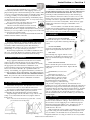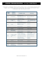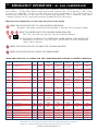
1
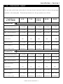
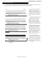
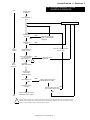
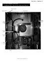
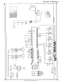
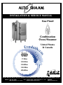
®
INSTALLATION & SERVICE MANUAL
Gas-Fired
Combination
Oven/Steamer
Combith
er
m
S
GA
Models:
United States
& Canada
®
6•10ML
7•14ML
10•10ML
10•20ML
12•18ML
20•20ML
W164 N9221 Water Street
-
PO Box 450
-
Menomonee Falls, Wisconsin 53052-0450
PHONE: 262.251.3800
FAX: 262.251.7067 • 800.329.8744 U.S.A.
262.251.1907 INTERNATIONAL
800.558.8744 U.S.A./CANADA
PRINTED IN U.S.A.
ONLY
U.S.A.
WEBSITE:
www.alto-shaam.com
#6011ML • 10/2001
®
GAS
COMBITHERM
INSTALLATION & SERVICE MANUAL
MODELS
6•10 ML , 7•14 ML , 10•10 ML , 10•20 ML , 12•18 ML & 20•20 ML GAS
SAFETY:
Do not store or use gasoline or other flammable vapors or liquids
in the vicinity of this or any other appliance.
WARNING:
Improper installation, adjustment, alteration, service or maintenance can
cause property damage, injury or death.
Read the installation, operating, and maintenance
instructions thoroughly before installing or servicing this equipment.
NOTE:
In some prominent location, instructions obtained from the local gas supplier must
be posted indicating procedures to be followed in the event that the user smells gas.
GAS FOOD SERVICE EQUIPMENT
ANS Z83.11.CGA 1.8-(1996) Food Service Equipment
ANS Z83.11.CGA 1.8-(1996) Manager Service Equipé
Underwriters Laboratories, Inc. ®
CLASSIFIED
GAS-FIRED FOOD EQUIPMENT
ANS Z83.12 • CAN 1.10 (1994) - OVEN
ANS Z83.12 • CAN 1.10 (1994) - FOUR
ANSI/NSF4
The information contained in this manual is important for the proper installation, use and
maintenance of this oven. Please read carefully and retain for future reference.
Improper connection of this appliance will nullify all warranties.
®
GAS
COMBITHERM
FOUR/CONVECTION VAPEUR
MANUEL D'INSTALLATION, DE MISE EN ROUTE
ET D'ENTRETIEN MODELES :
6•10 ML , 7•14 ML , 10•10 ML , 10•20 ML , 12•18 ML & 20•20 ML GAS
ADVERTISSEMENT
Ne pas entreposer ni utiliser de l'essence
ni d'autres vapeurs ou liquides inflammables
dans le voisinage de cet appareil,
ni de tout autre appareil.
ADVERTISSEMENT
Une installation, un ajustement, une altération, un service
ou un entretien non conforme aux normes peut causer des
dommages a'la propriété, des blessures ou la mort. Lisez
attentivement les directives d'installation, d'opération et
d'entretien avant de faire l'enstallation ou l'entretien
de cet équipement.
NOTE
En dernier reours, les instructions provenant du fournisseur local de
gas doivent être mises en evidence de maniere a indiquer les
procedures à suivre au cas ou l'utilizateur sentirait le gaz.
GAS FOOD SERVICE EQUIPMENT
ANS Z83,11.CGA 1.8-(1996) Food Service Equip.
ANS Z83.11.CGA 1.8-(1996) Manager Service Equipé
Underwriters Laboratories, Inc. ®
CLASSIFIED
GAS-FIRED FOOD EQUIPMENT
ANS Z83.12 • CAN 1.10 (1994) - OVEN
ANS Z83.12 • CAN 1.10 (1994) - FOUR
MIES EN GARDE
ANSI/NSF4
Les informations contenues dans ce manuel sont importantes pour l'installation l'utilisation
et l'entretien de ce four. S'il vous plait lisez-le tres attentivement et conservez-le. La nonapplication de ces consignes annule toutes garanties.
Operation and Care Manual #6011 • 3.
ML
TABLE OF CONTENTS
Gas Combitherm Installation & Service Manual
SECTION 1 - INSTALLATION
Page
1.1
Delivery/Unpacking . . . . . . . . . . . . . . . . . . . . . . . . . . . . . . . . . . . . . . . . . . . . . . . . . . . . . . . . . . . . . . . . . .1
1.2
Installation Requirements . . . . . . . . . . . . . . . . . . . . . . . . . . . . . . . . . . . . . . . . . . . . . . . . . . . . . . . . . . . . .1
1.3
Codes & Standards . . . . . . . . . . . . . . . . . . . . . . . . . . . . . . . . . . . . . . . . . . . . . . . . . . . . . . . . . . . . . . . . . .1
1.4
Unit Placement . . . . . . . . . . . . . . . . . . . . . . . . . . . . . . . . . . . . . . . . . . . . . . . . . . . . . . . . . . . . . . . . . . . . . .1
1.5
Clearances
. . . . . . . . . . . . . . . . . . . . . . . . . . . . . . . . . . . . . . . . . . . . . . . . . . . . . . . . . . . . . . . . . . . . . .1
1.6
Assembly
. . . . . . . . . . . . . . . . . . . . . . . . . . . . . . . . . . . . . . . . . . . . . . . . . . . . . . . . . . . . . . . . . . . . . .1
1.7
Air Supply
. . . . . . . . . . . . . . . . . . . . . . . . . . . . . . . . . . . . . . . . . . . . . . . . . . . . . . . . . . . . . . . . . . . . . .1
1.8
Electrical Connections . . . . . . . . . . . . . . . . . . . . . . . . . . . . . . . . . . . . . . . . . . . . . . . . . . . . . . . . . . . . . . .2
1.9
Water Connection . . . . . . . . . . . . . . . . . . . . . . . . . . . . . . . . . . . . . . . . . . . . . . . . . . . . . . . . . . . . . . . . . . .2
1.10
Waste Water Discharge . . . . . . . . . . . . . . . . . . . . . . . . . . . . . . . . . . . . . . . . . . . . . . . . . . . . . . . . . . . . . . .2
1.11
Gas Connections . . . . . . . . . . . . . . . . . . . . . . . . . . . . . . . . . . . . . . . . . . . . . . . . . . . . . . . . . . . . . . . . . . . .3
Type & Pressure • Connection • Leak Testing • Fuel Interlock System
1.12
Gas Exhaust
. . . . . . . . . . . . . . . . . . . . . . . . . . . . . . . . . . . . . . . . . . . . . . . . . . . . . . . . . . . . . . . . . . . . . .3
1.13
Pressure Chart . . . . . . . . . . . . . . . . . . . . . . . . . . . . . . . . . . . . . . . . . . . . . . . . . . . . . . . . . . . . . . . . . . . . . .4
Natural Gas • Propane Gas
1.14
Gas Flame Patterns . . . . . . . . . . . . . . . . . . . . . . . . . . . . . . . . . . . . . . . . . . . . . . . . . . . . . . . . . . . . . . . . . .5
1.15
Burner/Pilot Adjustments . . . . . . . . . . . . . . . . . . . . . . . . . . . . . . . . . . . . . . . . . . . . . . . . . . . . . . . . . . . . .6
#1
Checking Pressure . . . . . . . . . . . . . . . . . . . . . . . . . . . . . . . . . . . . . . . . . . . . . . . . . . . . . . . . . . . . .6
#2
Adjust Pilot Burner . . . . . . . . . . . . . . . . . . . . . . . . . . . . . . . . . . . . . . . . . . . . . . . . . . . . . . . . . . . . .6
#3
Manifold Pressure Adjustment . . . . . . . . . . . . . . . . . . . . . . . . . . . . . . . . . . . . . . . . . . . . . . . . . . . .6
#4
Ignition & Burner Check . . . . . . . . . . . . . . . . . . . . . . . . . . . . . . . . . . . . . . . . . . . . . . . . . . . . . . . . .6
#5
Verify Sequence of Operation . . . . . . . . . . . . . . . . . . . . . . . . . . . . . . . . . . . . . . . . . . . . . . . . . . . . .6
1.16
Honeywell Valve System • Sequence of Operation . . . . . . . . . . . . . . . . . . . . . . . . . . . . . . . . . . . . . . . .7
1.17
Installation Checklists . . . . . . . . . . . . . . . . . . . . . . . . . . . . . . . . . . . . . . . . . . . . . . . . . . . . . . . . . . . . . . . .8
Installation Inspection • User/Operator Instructions • End of the Day •
Functions • Oven Use Explanation • Service Panel Use • Cleaning
SECTION 2 - SERVICE & PARTS
2.0
Gas Operation Schematic . . . . . . . . . . . . . . . . . . . . . . . . . . . . . . . . . . . . . . . . . . . . . . . . . . . . . . . . . . . . .9
2.1
Service Contract . . . . . . . . . . . . . . . . . . . . . . . . . . . . . . . . . . . . . . . . . . . . . . . . . . . . . . . . . . . . . . . . . . .10
2.2
Control Troubleshooting . . . . . . . . . . . . . . . . . . . . . . . . . . . . . . . . . . . . . . . . . . . . . . . . . . . . . . . . . . . . .11
2.3
Troubleshooting . . . . . . . . . . . . . . . . . . . . . . . . . . . . . . . . . . . . . . . . . . . . . . . . . . . . . . . . . . . . . . . . . . . .12
2.4
Emergency Operation . . . . . . . . . . . . . . . . . . . . . . . . . . . . . . . . . . . . . . . . . . . . . . . . . . . . . . . . . . . . . . .13
2.5
Parts
2.6
Gas Combitherm Photograph with Exterior Components . . . . . . . . . . . . . . . . . . . . . . . . . . . . . . . . . .16
2.7
Control Panel Operation . . . . . . . . . . . . . . . . . . . . . . . . . . . . . . . . . . . . . . . . . . . . . . . . . . . . . . . . . . . . .17
2.8
Left Side Components - Model 6•10ML, 7•14ML, 10•10ML, 10•20ML, and 12•18ML . . . . . . . . . . . . . . . .18
. . . . . . . . . . . . . . . . . . . . . . . . . . . . . . . . . . . . . . . . . . . . . . . . . . . . . . . . . . . . . . . . . . .14,15
Left Side Components - Model 20•20ML . . . . . . . . . . . . . . . . . . . . . . . . . . . . . . . . . . . . . . . . . . . . . . . . .19
2.9
Service Views . . . . . . . . . . . . . . . . . . . . . . . . . . . . . . . . . . . . . . . . . . . . . . . . . . . . . . . . . . . . . . . . . . . . .20
Wiring Diagram - Models 6•10ML, 7•14ML, 10•10ML, 10•20ML and 12•18ML . . . . . . . . . . . . . . . . . . . . . .21
Wiring Diagram - Model 20•20ML . . . . . . . . . . . . . . . . . . . . . . . . . . . . . . . . . . . . . . . . . . . . . . . . . . . . . .22
Transportation Damage & Claims • Alto-Shaam Limited Warranty . . . . . . . . . . . . . . . . . . . . . . . . . . .23
Installation • Section 1
1.1 - DELIVERY/UNPACKING
1.5 - CLEARANCES
Upon receipt of the Combitherm ML Gas combination
oven/steamer, check the exterior of the shipping crate for any
physical damage that could result in damage to the contents. If the
oven was not received from the carrier in an upright position, there
is a strong possibility of concealed damage. Uncrate the unit
carefully and inspect for any transit damage. Immediately report
any damage to the delivery freight carrier. See Transportation Damage
Clearance to left side wall is 8 inches (203mm), but in order to
provide sufficient clearance for service, 20 inches (508mm) must
be allowed on the left-hand side of the unit. If this clearance
cannot be provided, it will be necessary to disconnect the gas,
water and drain connection in order to move the oven via a lift
truck to gain access for servicing, and this will not be covered by
warranty. Clearance to right side wall is 6 inches (152mm).
Clearance to rear wall is 1 inch (25mm). These clearances apply
whether the construction wall type is combustible or noncombustible.
Do not install the oven within 20 inches (508mm) of
another heat producing appliance such as a fryer, or open top
range, etc., since the heat from these appliances may cause damage
to the controls of this oven, and this will void the warranty.
and Claims section located in this manual.
The oven must remain on the pallet while being moved
to the installation site by fork-lift or pallet-lift truck.
Check to ensure that all items have been received
with each unit. Save all information and instructions
packed inside the unit. Complete and return the warranty card to
the factory as soon as possible to assure prompt service in the event
of a warranty parts and labor claim.
Note that all claims for warranty must include the full model
number and serial number of the unit.
1.2 - INSTALLATION REQUIREMENTS
In order to eliminate any operation problems and to insure
proper operation, the installation of this oven must be done in
accordance with the instructions given in this manual by a
qualified installer. Failure to do so may cause damage to the oven
and building, or cause personal injury to personnel.
The following requirements are needed for installation of the
this oven: Air Supply, Electrical Connections, Water Connections,
Gas Connections, Gas Exhaust, and Waste Water Discharge.
1.3 - CODES & STANDARDS
The gas appliance installation must be done in accordance
with local codes, and in the absence of local codes, with the
National Fuel Gas Code, ANSI Z223.1 (latest edition). In Canada,
the appropriate code is the Natural Gas Installation Code,
CAN/CGA-B149.1 or the Propane Installation Code, CAN/CGA-B.
These codes must be adhered to by a qualified installer concerning: Gas Plumbing, Gas Appliance Installation, Commercial
Cooking Ventilation, Water and Plumbing, and OSHA Regulations.
The installation surface must be non-combustible (unable to
burn). See your local codes or the National Fuel Gas Code for the
definition of combustible and non-combustible construction.
1.4 - UNIT PLACEMENT
Stand unit in level position. The adjustable feet can be used to
overcome an uneven floor to ensure that the unit is level.
It is strongly recommended that table top models be on the
original stand or one that is stable, open, level, and noncombustible. Recommended height is 23 inches (620mm).
Adapt the height of the floor models for easy "roll-in" of the
trolley or cart. Ensure that the unit is level, right-to-left and
back-to-front.
Note: Some units can be stacked on top of each other – but this
process must be done at the factory
Correct positioning
Incorrect positioning
1.6 - ASSEMBLY
oven front
EXHAUST GAS/FLUE DIVERTER
Install the diverter piece as shown. Make sure the
wire screen is in place before attaching with enclosed
screws.
SOUND ABSORBER
Screw the sound absorber onto the threaded
nipple on the top back left side of the oven.
DRIP TRAY
Fasten the drip tray support with two screws
(if necessary) on Models 6•10 and 10•10. The
drip tray can then be hung from the drip pan
support.
HAND SHOWER HOLDER
Remove the left side panel. Fasten the hand shower
holder, using four nuts and washers. Replace the left
side panel.
GUIDE RAILS (FOR OVENS WITH
CARTS)
Mount the rear support using two bolts with washers and
spring washers at the rear under
the unit. Fit the guide rails with
the welded studs in the slotted holes
in the rear support and fasten using
nuts, washers and spring washers from the back (do not
tighten, leave loose). Then attach the rails at the front of the unit on
the unit base using two bolts with washers and spring washers .
Push the trolley into the unit; center it and close the door. Push the
guide rails at the rear so that they touch the cart. Tighten the
nuts so that the rails are locked in this position. Check to see
that the seal between the oven and cart make a good contact over
its total length.
1.7 - AIR SUPPLY
Installation of this oven must provide an adequate flow of
fresh air for the combustion of the gas. The bottom of the oven is
the area that is used for supplying air for combustion purposes.
Instructions must be left with the user to keep this area clear of
material which might block the flow of the combustion or
ventilation air to the oven.
Make sure that the oven has plenty of ventilation air around it
to provide cooling air for the electrical and gas components. The
area around the oven should be clear of any obstructions which
might retard the flow of cooling air. Failure to do so may result in
Installation and Service Manual #6011ML • 1.
Installation • Section 1
damage to the control components and
will void the warranty.
Do not use circulating fans on the
floor as this will cause the loss of pilot
flame and affect burner operation.
Local codes and the National Fuel
Gas Code give rules for determining the
amount of fresh air necessary for
combustion and ventilation of
commercial cooking appliances. The
codes will help determine if additional
outside air may be necessary to meet health and safety regulations.
1.8 - ELECTRICAL CONNECTIONS
Ensure that the electrical supply matches the specification on
the oven data plate. Gas models available for USA and Canada are
typically rated for 110-120V, 60Hz, 1Ph. An electric cord is
supplied and is ready to use. Fuses are located inside the unit at
the left-hand side. The oven must be electrically grounded in
accordance with local codes, or in the absence of local codes, with
the National Electrical Code, ANSI/NFPA 70 (latest edition) or in
Canada with the Canadian Electrical Code, CSA C22.1. The
installation of any wiring or electrical connections must be done by
a licensed electrical contractor.
ACCESSING CONTROL AREA
To access the electrical/control system, make sure to disconnect
power and ensure the gas supply is shut OFF before removing the
left side panel.
The electrical diagram is affixed inside the left-hand side control
area. A copy of the electrical diagram is shown at the back of this
manual. Service or changes must be done by a licensed electrical
contractor and in accordance with local codes and regulations.
1.9 - WATER CONNECTION
The oven must be connected to a COLD water supply of
potable (drinkable) quality.
The on-site water supply must have a shut-off valve. If local
regulations require a back-flow preventer, have this installed.
Always observe local water regulations.
A water conditioner is highly recommended, especially if the
water hardness is NOT pH5 and 9. Please contact the factory for
assistance with a water conditioner.
The water pressure requirements are a minimum of 30 psi
and a maximum of 120 psi. The connecting pipe is 3/4" and is
under the unit.
ASSEMBLY (See illustration at bottom of this page)
The water connection is installed in conjunction with the hand
shower spray. In the illustration below, all connections indicated
with the symbol ✿ are to be assembled with teflon sealing tape.
A. Screw T-piece onto the unit water supply inlet.
B. Assemble double nipples and water tap, and hose.
C. Slide O-ring over the threading from the hand shower.
D. Screw together the hose, seal, and the hand shower.
E. Hang the hand shower in its holder on the unit.
F. Screw the hose and filter onto the cold water connection.
G. Do not forget the filter!
1.10 - WASTE WATER DISCHARGE
The oven must discharge through an indirect waste pipe by
means of air gap, i.e., vacuum break. If such piping is not
provided, serious damage can occur to the unit and to the cooking
product.
CONNECTION
Install the elbow provided. Make
certain the washers provided are used.
An illustrated example of water drainage
for the Gas Combitherm is shown.
Installation and Service Manual #6011ML • 2.
Installation • Section 1
1.11 - GAS CONNECTIONS
The installation of this oven must be done by a qualified
installer familiar with the local codes and regulations governing
the installation of commercial gas appliances.
The installation must be done in accordance with local codes,
and in the absence of local codes, with the National Fuel Gas Code
ANSI Z223.1 (latest edition). In Canada, the appropriate code is
the Natural Gas Installation Code, CAN/CGA-B149.1 or the
Propane Installation Code, CAN/CGA-B.
GAS TYPE & PRESSURE
Check the oven nameplate information to determine the type of
gas the Combitherm Gas Oven/Steamer was manufactured for
(natural or propane) and make sure the gas supply matches the
nameplate information.
Check the nameplate to determine the gas manifold pressure for
the oven. The minimum supply pressure to the oven must exceed
this value by at least 1" w.c. It is recommended that the supply
pressure be between 5" w.c. and 14" w.c. for natural gas, and 11"
w.c. and 14" w.c. for propane. An alternate gas supply inlet may be
required for installation sites at elevations of 3,000 feet (914m) above sea
level. Please check with factory.
Should conversion to the opposite fuel be desired, conversion
parts must be ordered from the factory. Conversion must be done by
a qualified service person only. Always remember to reflect the
conversion on the oven's nameplate.
between the building gas supply and where it attaches to the rear
of the oven.
The routing of the flexible connector must not be done under
the oven. The temperatures during operation are too hot for safe
operation. Gas piping should be installed from the point of gas
connection at the bottom, front of the oven to the back of the oven
where the flexible connector may be used. See the
illustration for the recommended procedure.
The gas piping must never be run under the
burner––there is danger of overheating.
LEAK TESTING
If a pressure leak test above 1/2 psi is to be done on the building supply gas piping, the shut-off gas valve and oven inlet gas
supply line must be disconnected from the building supply piping
before conducting the pressure test. Failure to do so may result in
damage to the manual gas valve and/or gas components in the oven.
If any gas leak tests are to be conducted at pressures equal to or
below 1/2 psi, the manual gas shut-off valve upstream of the oven
must be turned off before conducting the tests.
Leak testing of the internal oven piping system was conducted
before shipping the oven from the factory. If additional testing is
needed, it should only be conducted at normal gas supply
pressures. If the testing is performed using combustible gas in the
piping, the leak checking should be done with a soap solution
(bubble checking).
GAS CONNECTION
The minimum size of the gas piping or flexible connector is 1/2"
except for the Model 20•20 which is 3/4". For long runs of gas
piping, the pipe diameter must conform to the tables in the
National Fuel Gas Code, ANSI/NFPA Z223.1.
A listed gas shut-off valve must be installed upstream of the
appliance for shutting off the gas supply during servicing. This
valve should be installed so that it is accessible with the appliance
in its normally installed position.
If the oven or its stand is supplied with casters – the installation
must be done with a flexible connector that complies with the
Standard for Connectors for Movable Gas Appliances, ANSI
Z21.69; or in Canada, Connectors for Movable Gas Appliances,
CAN/CGA-6.16-M87. When using a flexible connector, a quick
disconnect device must also be used that complies with the
Standard for Quick-Disconnect Devices for Gas Fuels, ANSI
Z21.41; or in Canada, Quick Disconnect Devices for Use with Gas
Fuels, CAN1-6.9.
When a quick disconnect device and flexible connector are used,
a restraining device must be used which will limit the movement
of the appliance to prevent damage to the connector or quick
disconnect. An example of such a system is to use 2000 pound test
stainless steel cable attached to a structural member of the kitchen
wall behind the oven. The attachment means should have a quick
connect snap such that it can be disconnected when the appliance
needs to be moved away from the wall.
The other end of the cable should be
permanently attached to the rear frame of
the oven. The length of the cable should be
such that no strain is ever placed upon the
flexible gas connector if the appliance is
accidentally moved without first
disconnecting the gas connector.
The flexible connector should be routed
so that it forms a downward "U" loop
NEVER CHECK FOR LEAKS USING AN OPEN FLAME.
The use of electronic combustible gas leak detectors is
helpful, but they can be oversensitive.
They may find leaks that are not visible
when checking with a liquid solution,
and therefore, present no hazard.
When starting unit after initial installation, the gas lines must be free
of air. It may take up to 30 minutes to do this. If, after this time there is
no pilot, call for factory assistance.
FUEL INTERLOCK SYSTEM
Local codes may require that the fuel supply to the oven be
interlocked to the ventilation hood. If that is the case, a separate
electrically operated gas valve must be installed in the gas line.
The selection of the valve will be up to the installer, but the valve
should be recognized by the authority having jurisdiction.
1.12 - GAS EXHAUST
The oven is not for direct connection to a chimney vent system
or for direct connection to a horizontal exhaust system. The oven
must be installed under a ventilation hood listed to ANSI/UL 705
(latest edition), and the installation must be done in accordance
with the ANSI/NFPA 96-1987, Standard for Ventilation Control
and Fire Protection of Commercial Cooking Operations.
The oven is supplied with a flue diverter that must
be installed on the oven prior to installation. See
Assembly at the front of this manual. The operators of
the oven should be instructed not to place any
material on top of the oven that would obstruct the
flow of flue products out the opening. They should
also be instructed that the flue gases are hot, and that
any material or items they place on top of, or in front
of the flue defector could be damaged or cause fire
hazard.T I O N G U I D E L I N E S
Installation and Service Manual #6011ML • 3.
Installation • Section 1
1.13 - P R E S S U R E C H A R T
The gas valve, pilot burner and nozzles for the main burner have been fitted according to the gas type
specified on the name plate. Technical specifications for the gas system are as follows:
Combitherm
ML Gas Model
6•10
7•14
10•10
12•18
10•20
20•20
Natural Gas
Connected pressure rating
7 in. W.C.
7 in. W.C.
7
in W.C.
7
in W.C.
7
in W.C.
Min. connected pressure
5 in. W.C.
5 in. W.C.
5
in. W.C.
5
in. W.C.
5
in. W.C.
Max. connected pressure
14 in. W.C.
14 in. W.C.
14
in. W.C.
14
in. W.C.
14
in. W.C.
—
—
—
—
220
315
280
400
Manifold pressure
3.5 in. W.C.
3.5 in. W.C.
Gas Consumption
45 cu.ft/hr
81.9 cu.ft/hr
67 cu.ft/hr
112 cu.ft/hr
168.1 cu.ft/hr
45,500 Btu/hr
82,000 Btu/hr
68,000 Btr/hr
113,000 Btu/hr
170,000 Btu/hr
Connected pressure rating
11 in. W.C.
11 in. W.C.
11
in. W.C.
11
in. W.C.
11
in. W.C.
Min. connected pressure
11 in. W.C.
11 in. W.C.
11
in. W.C.
11
in. W.C.
11
in. W.C.
Max. connected pressure
14 in. W.C.
14 in. W.C.
14
in. W.C.
14
in. W.C.
14
in. W.C.
—
—
—
—
—
135
190
170
220
220
Manifold pressure
10 in. W.C.
10 in. W.C.
10
Gas Consumption
17.7 cu.ft/hr
32.9 cu.ft/hr
26.5 cu.ft/hr
44.1 cu.ft/hr
66.5 cu.ft/hr
Gross thermal output
45,500 Btu/hr
82,000 Btu/hr
68,000 Btu/hr
113,000 Btu/hr
170,000 Btr/hr
Nozzle pilot burner
Nozzle burner
Gross thermal output
3.5
in. W.C.
3.5
in. W.C.
—
400
3.5
in. W.C.
Propane Gas
Nozzle pilot burner
Nozzle burner
in. W.C.
Installation and Service Manual #6011ML • 4.
10
in. W.C.
10
in. W.C.
Installation • Section 1
1.14 - GAS FLAME PATTERNS
When starting the unit after initial installation, the gas lines must be free of air. It may take up to
30 minutes to do this. If, after this time there is no pilot, call for factory assistance.
For all practical reasons this will be the
only check necessary during initial
operation by the installer. After the
installation is complete the oven needs to
be test fired to ensure that the system is
operating properly. Follow the operating
instructions posted on the front of the
unit.
The flame pattern both under hot and
cold conditions should be stable on all
burner ports and there should be no
lifting or blowing after 15 seconds of
operation. There is no air shutter
adjustment on these burners and if the
flame pattern does not match that shown,
contact the factory for further directions.
Make sure that the pilot burner is
lighting quickly from the electric ignitor.
Then make sure that the main burner is
lighting quickly (within 4 seconds),
smoothly (no harsh noise), and without
any problems. While the oven is COLD,
cycle the oven ON and OFF five times to
make sure everything is working
properly. Allow the unit to heat up for 5
minutes and repeat the process.
Check the flame pattern on the
burners. The flames should be blue in
color with little or no yellow in the flame.
On propane gas some yellow tipping is
normal, but there should be no indication
that soot will form on the combustion
chamber walls, pilot or main burner from
the yellow tipping.
Installation and Service Manual #6011ML • 5.
Installation • Section 1
1.15 - BURNER/PILOT ADJUSTMENTS
The gas units units are equipped with intermittent pilot-based
operation and are fitted with a Honeywell gas valve. The gas
valve has a built-in pressure regulator and a hot surface
intermittent pilot ignition control for safe operation. The valve has
a step open feature (standard) for natural gas operation. For
propane, a full open feature is standard. Explanation of the gas
valve is shown in the illustration.
Step #1 - CHECKING PRESSURE
A. Turn gas connection OFF. Open gas inlet pressure
connection cap and unscrew the tap. Connect pressure
gauge at pressure tap. Read pressure.
B. If pressure measured is higher or lower than that
specified in the Pressure Table located in this
manual, do not proceed with initial operation.
C. Remove pressure gauge, screw in the tap and close with
protective cap.
Step #2 - ADJUST PILOT BURNER
The pilot burner assembly installed in your unit is tested prior
to shipment and does not require any adjustment. If adjustment is
desired, follow these instructions. This step must be performed by a
qualified person only.
A. Turn main power switch ON, and switch the ignition
control switch on the gas valve to ON position.
B. Set temperature and timer and press the START/STOP key.
Follow oven operational instructions.
C. The pilot flame should be lit and blue in color with no or
very little yellow peaks.
Step #3 - MANIFOLD PRESSURE ADJUSTMENT
The gas valve has a built-in pressure regulator and regulates the
manifold pressure according to specification presented in the
Pressure Table in this manual. The valve requires no adjustment.
However, if adjustment is desired, follow the instructions below.
This must be performed by a qualified person only.
A. Turn power and gas supply OFF.
B. Remove protective cap from outlet gas/manifold gas tap.
Unscrew, connect pressure gauge.
C. Turn main power switch ON, and switch the ignition
control switch on the gas valve to ON position.
D. Select program, set temperature and timer, and press the
START/STOP key. Follow oven operational instructions.
E. The gas valve will open and the main burner flame should
be established.
F. Measure manifold pressure. If it requires adjustment, open
the cap on the pressure regulator and adjust the screw for
increased or decreased gas pressure.
DO NOT SET THE REGULATOR TO ANY OTHER SETTING
OTHER THAN TO THE DATA SPECIFIED IN THE
PRESSURE CHART IN THIS MANUAL.
Step #4 - IGNITION & BURNER CHECK
For all practical reasons this will be the only check necessary
during initial operation by the installer. After the installation is
complete the oven needs to be test fired to ensure that the system is
operating properly. Follow the operating instructions posted on
the front of the unit.
The flame pattern both under hot and cold conditions should be
stable on all burner ports and there should be no lifting or blowing
after 15 seconds of operation. See the illustration in this manual for
the proper flame pattern. There is no air shutter adjustment on these
burners and if the flame pattern does not match that shown,
contact the factory for further directions.
Make sure that the pilot burner is lighting quickly from the
electric ignitor. Then make sure that the main burner is lighting
quickly (within 4 seconds), smoothly (no harsh noise), and without
any problems. While the oven is COLD, cycle the oven ON and
OFF five times to make sure everything is working properly.
Allow the unit to heat up for 5 minutes and repeat the process.
Check the flame pattern on the burners. The flames should be
blue in color with little or no yellow in the flame. On propane gas
some yellow tipping is normal, but there should be no indication
that soot will form on the combustion chamber walls, pilot or main
burner from the yellow tipping.
Step #5 - VERIFY SEQUENCE OF OPERATION
The Gas Combitherm is fitted with an intermittent pilot and a
Honeywell gas valve, which provides automatic pilot ignition and
main burner ignition. The ignition control system will routinely
undergo three ignition trials (for pilot burner ignition) before
identifying an ignition failure to timeout. The normal sequence of
operation is illustrated on the following page of this manual.
When starting unit after initial installation, the gas lines must be
free of air. It may take up to 30 minutes to do this. If, after this
time there is no pilot, call for factory assistance.
G. Turn the gas valve OFF or to PILOT position.
H. Close pressure regulator and manifold/outlet gas tap with
protective caps.
NOTE: If you do not understand this procedure, do not perform
any changes. Call the factory for assistance.
Installation and Service Manual #6011ML • 6.
Installation • Section 1
Start
1.16 - Honeywell SmartValveTM SYSTEM
SEQUENCE OF OPERATION
Apply 24 VAC
to Appliance
Thermostat Calls for
Heat
Five Minute Retry Delay
Flame Signal
Detected!
YES
NO
Internal Check
Okay?
Trial for
Ignition
NO
Three Second Flame Failure
Recycle Delay
• Pilot Valve Opens
• Igniter Powered
Pilot Lights and Flame
is sensed during
Trial for Ignition?
YES
Main
Burner
Operation
• Pilot Valve/Ignition Off
• Wait for Flame Signal to
Disappear
NO
• Pilot Valve Closes
• Igniter Off
1
• Igniter Off
• Main Valve Opens
Electronic Fan
Timer (EFT)
Output Energizes
YES
Flame Signal Lost?
NO
Thermostat Call for
Heat Ends
• Main and Pilot Valves Close
• EFT Output De-energizes
Flame Lost More than Five
Times in One Call for Heat?
NO
YES
• Main and Pilot Valves Close
• EFT Output De-energizes
End
1
Igniter will turn off about 30 seconds into the trial for ignition if the pilot flame has not lit. It will turn back on for
the final 30 seconds of the 90 second trial for ignition. The pilot valve will be energized during the entire trial for
ignition. This is normal operation for this gas ignition system.
Installation and Service Manual #6011ML • 7.
Installation • Section 1
1.17 - INSTALLATION CHECKLISTS
FUNCTION
INSTALLATION INSPECTION
CHECK LIST
✔
✔
✔
✔
✔
✔
✔
✔
✔
✔
✔
✔
CHECKLIST
Transport damage?
No gas hose/tube under the burner?
No flexible gas line or tubing under oven?
Non-combustible installation floor?
Minimum clearances around oven adhered to?
Unit not adjacent to heat producing equipment?
Service clearance available?
Gas and exhaust installation according to regulations?
Water softener/conditioner installed according to regulations?
Water drainage according to instructions and regulations?
Shelf rack slid in completely and fastened with safety latches?
Installation/operation manual and cookbook close by?
✕
✕
✕
✕
✕
Turn main water inlet and gas supply ON.
Switch unit power ON.
All interior oven lights lit?
Did pilot ignite correctly?
Did burner ignite correctly?
OVEN USE EXPLANATION
CHECK LIST
USER/OPERATOR INSTRUCTIONS
Demonstrate
➡ how to light the pilot
➡ the removable drip tray
➡ the removable shelf rack with safety latches
➡ how the door magnet switch functions
CHECKLIST
• Never store any combustible material under, on top of, or
beside this oven.
• Do not place any other heat producing appliances within 20
inches of this oven.
• Make sure the oven has plenty of ventilation air around it to
provide cooling air for the electrical and gas components.
• Do not obstruct the flow of combustion and ventilation air
around the oven.
• The bottom of the oven is the area that is used for supplying air
for combustion purposes. Keep this area clear of material which
could block the flow of air to the oven.
• Once a sufficient air supply has been established, do not reduce
the size of the room, increase the sealing of window and outside
doors, or close or remove air vents. Gas units use fresh air.
• Do not place any material on top of the oven that would
obstruct the flow of flue products. Flue gases are hot and any
material or items placed on top of, or in front of, the flue
deflector could result in a fire.
• Before servicing or cleaning this oven, disconnect the electrical
supply.
• All servicing and maintenance should be performed by a
qualified service agent.
• Clean the oven on a routine basis.
• Do not store flammable items (shower hose, plastic waste cans,
etc.) under the unit because of its excessive heat.
• A maintenance contract is highly recommended.
SERVICE PANEL USE
CHECK LIST
Explain
➧ the indicators "no water" and "convection/steam"
➧ the cooking programs and settings
➧ the importance of preheating
➧ the handbook
CLEANING
CHECK LIST
Explain or demonstrate
➧ the handshower
➧ the daily cleaning process
➧ the monthly cleaning process
➧ replacing the plug-in door gaskets
➧ cleaning agents are caustic, rinse the unit well
END OF THE DAY
CHECK LIST
✕ Turn the unit OFF.
✕ Follow local regulations; if required, extinguish the pilot.
✕ Leave the door ajar.
Installation and Service Manual #6011ML • 8.
Service • Section 2
2.0 - Combitherm Gas Operation Schematic
Combitherm Gas Plumbing System
condensate water
Steam
drain
Water is used for generating steam and for cooling the drain water.
Steam is sprayed into the oven by means of a fan wheel.
The water is sprayed over the hottest area in the oven and is converted into steam.
Installation and Service Manual #6011ML • 9.
Service • Section 2
2.1 - SERVICE CONTRACT
The Alto-Shaam Gas Combitherm oven/steamer has a
specification plate affixed on the left-hand side panel of the
unit. The plate includes electrical and gas connection
specifications and should be verified prior to installation.
If any servicing help is required, contact the factory.
Remember to provide the model number and serial number
of the unit. This information is provided on the nameplate
(see examples).
Alto-Shaam urges the user to maintain a record of service performed on the Combitherm Gas Oven/Steamer.
Model: _______________
Gas Type: _____________
Date
_____
_____
_____
_____
_____
_____
_____
_____
_____
_____
_____
_____
_____
_____
_____
_____
_____
_____
_____
_____
_____
_____
_____
_____
Problem Detected
_______________________________________________
_______________________________________________
_______________________________________________
_______________________________________________
_______________________________________________
_______________________________________________
_______________________________________________
_______________________________________________
_______________________________________________
_______________________________________________
_______________________________________________
_______________________________________________
_______________________________________________
_______________________________________________
_______________________________________________
_______________________________________________
_______________________________________________
_______________________________________________
_______________________________________________
_______________________________________________
_______________________________________________
_______________________________________________
_______________________________________________
_______________________________________________
Serial No. _____________
Correction Performed
________________________________________________________
________________________________________________________
________________________________________________________
________________________________________________________
________________________________________________________
________________________________________________________
________________________________________________________
________________________________________________________
________________________________________________________
________________________________________________________
________________________________________________________
________________________________________________________
________________________________________________________
________________________________________________________
________________________________________________________
________________________________________________________
________________________________________________________
________________________________________________________
________________________________________________________
________________________________________________________
________________________________________________________
________________________________________________________
________________________________________________________
________________________________________________________
Installation and Service Manual #6011ML • 10.
2.2 -
CONTROL TROUBLESHOOTING •
ML
Gas Combitherm
In the event of a Combitherm malfunction during operation, an error code and message will appear in the
display to assist in finding a rapid solution to the problem. The following is a list of all error codes
including the possible cause along with a solution.
ERROR
CODE
E 01
E 02
E 03
DISPLAY
MESSAGE
Low water level
EL-temperature
too high
Fan fault
POSSIBLE CAUSE
SOLUTION
Water supply is closed
Open water supply.
Solenoid valve dirt screen soiled
Remove and clean screen.
Solenoid valve defective
Call service.
Connection box ventilation
defective
Air supply blocked
Allow steamer to cool down or
continue cooking with a lower
cooking compartment temperature.
Call service.
Motor temperature monitor has
tripped.
External fuse has blown
Call service.
Fan motor defective
Call service.
E 04
EL-fan fault
Auxiliary fan defective
Call service.
E 05
Gas fault
Gas supply interrupted
Open gas supply.
E 11
E 21
Oven over temp.
Oven probe error
Oven overheating
Call service.
Oven sensor defective
Call service.
Water supply closed
Open water supply.
Condenser over-temp
Condenser overheating due to
connection to hot water supply
Connect steamer to a cold water
supply and switch oven ON.
Condenser probe
error
Solenoid valve dirt screen soiled
Remove and clean screen.
Solenoid valve defective
Call service.
Condenser sensor defective
Call service.
E 15
E25
E 22
CTC error
KTM sensor defective
Select cooking programs by time.
Call service.
E 24
Bypass probe error
Bypass sensor defective
Call service.
E 80
E 95
E 96
ID error
Software error
Connection broken
Controller defective
Call service.
Installation and Service Manual #6011ML • 11.
2.3 -
T R O U B L E S H O OT I N G •
ML
Gas Combitherm
Additional malfunctions can occur during operation which do not result in error codes or display
messages. These irregularities are described as follows:
FAULT
POSSIBLE CAUSE
REMEDY
Air intake plate not properly closed
Close air intake plate properly
Cooking compartment
temperature set too high
Set temperature lower and extend
cooking time
Not preheated
Preheat: See Preheating instructions
The display is dark and does not
illuminate when switched ON
Mains lead not connected
External fuse has blown
Call Service
No interior oven light
Interior oven light defective
Call Service
Water jet from the exhaust air
opens when door is closed
Steam measuring cable soiled
Clean steam measuring cable
Steamer drain clogged
Clean drain
Pools of water in the cooking
compartment
Drain is clogged
Flush condenser and steamer
drain. Inspect and clean drain
system on site.
Clouds of steam from the
exhaust air opening at the
top of the steamer
Moisture vent valve in drain of
cooking compartment jammed
Clean and flush
(move back and forth)
Uneven browning
If the fault cannot be remedied using the tips in this list,
please call a local authorized Service Agency.
Alto-Shaam has established a twenty-four hour emergency
service call center to offer immediate customer access to a
local authorized service agency outside of
standard business hours. The emergency service
access is provided exclusively for Alto-Shaam
equipment and is available throughout the
United States through the use of Alto-Shaam's
t o l l - f r e e n u m b e r. E m e r g e n c y s e r v i c e a c c e s s i s
available seven days a week including holidays .
Installation and Service Manual #6011ML • 12.
E M E R G E N C Y O P E R AT I O N •
2.4 -
Gas Combitherm
ML
In the event of an error code, operation of the ML Gas Combitherm can be continued on a limited basis for a
short duration. Cooking times may be longer than normal operation and close monitoring of the cooking
process is recommended. Contact an authorized service agency immediately if the problem cannot be
rectified with simple steps in the previous troubleshooting guidelines. Error conditions under which
continued operation can be conducted are indicated by YES in the chart show below.
When the oven malfunctions, an error code will appear in the display.
PRESS THE START/STOP KEY TO ACKNOWLEDGE THE ERROR.
The keys for the usable operational modes will begin to flash and can be operated normally.
SELECT AND PRESS ONE OF THE COOKING MODES INDICATED.
The oven control will only respond to the oven mode keys flashing.
SET THE OVEN CONTROLS AS IF OPERATING UNDER NORMAL CIRCUMSTANCES.
Depending on the error code involved, oven function, such as temperature
range, may be limited.
PRESS THE START/STOP KEY TO BEGIN THE COOKING PROCESS.
PRESS THE START/STOP KEY WHEN THE TIMER EXPIRES.
WHEN THE OVEN FAULT IS CORRECTED, THE COMBITHERM WILL RETURN TO NORMAL OPERATION.
ERROR
CODE
DISPLAY MESSAGE
GAS
ELECTRIC
STEAM
MODE
1
SUPERHEATED
STEAM MODE
CONVECTION
MODE
RETHERM
MODE
DELTA - T
MODE
NO
YES
Up to 284°F
(140°C)
NO
Up to 284°F
(140°C)
NO
E01
Low water level
YES
YES
NO
NO
E02
EL-temperature too high
YES
YES
YES
E03
Fan Fault
NO
YES
Up to 212°F
Up to 284°F
(140°C)
NO
up to 356°F
(140°C)
Up to 284°F
(140°C)
NO
E04
EL-fan fault
NO
YES
YES
E05
Gas fault
YES
NO
YES
Up to 284°F
(140°C)
YES
Up to 284°F
(140°C)
YES
Up to 284°F
(140°C)
YES
Up to 284°F
(140°C)
YES
E15
Condenser oven temperature
YES
YES
NO
NO
Up to 356°F
(180°C)
NO
YES
E21
Oven probe error
NO
YES
212°F only
NO
NO
NO
NO
(100°C)
(100°C)
E22
CTC error
YES
YES
YES
YES
YES
YES
YES
E23
SG-probe error
YES
YES
YES
YES
YES
YES
YES
E24
Bypass probe error
NO
YES
Up to 210°F
NO
YES
NO
YES
(99°C)
E25
Condenser probe error
(20.20G AS
E26
NO
YES
NO
YES
ONLY )
SG probe error
3
YES 2
(180°C)
YES
Up to 356°F
(180°C)
YES
3
Up to 356°F
YES
YES
NO
YES
YES
YES
YES
YES
NO
YES
YES
YES
YES
YES
YES
E81
Program memory error
YES
YES
YES
YES
YES
YES
YES
E83
Algo. error
YES
YES
YES
YES
YES
YES
YES
E89
12C error
YES
YES
YES
YES
YES
YES
YES
2
3
Cooking time increases significantly. Food on the upper shelves is finished first.
Water injection into the condenser is activated for the entire cooking mode (high water consumption).
When error codes E23 and E26 appear simultaneously, steam generator does not preheat.
Installation and Service Manual #6011ML • 13.
2
YES
SG pump error
1
NO
2
SG heat error
E34
YES
3
2
YES
SG probe error
YES
2
NO
E23 &
E23
E33
YES
3
Up to 356°F
(180°C)
YES
YES
YES
3
2.5 - Parts • Combitherm ML Gas
1.
2.
3.
4.
5.
6.
7.
8.
9.
10.
11.
12.
13.
14.
15.
16.
17.
18.
19.
20.
21.
22.
23.
23.
24.
25.
26.
27.
28.
29.
30.
31.
32.
33.
34.
35.
36.
37.
38.
39.
40.
41.
42.
43.
44.
45.
46.
47.
48.
49.
50.
51.
Service • Section 2
PART DESCRIPTION
6•10GML
7•14GML
10•10GML
10•20GML
12•18GML
20•20GML
Side Racks, Left
Side Racks, Right
Roll-in Cart, Complete
Trolley Drip Pan
Trolley Gasket
Side Trolley Seals, 4"
Trolley Gasket Upper Seal, old
Trolley Gasket Lower Seal, old
Trolley Guide
Door Drip Tray
Door (no handle or gasket)
Door Handle
Door Latch
Door Latch Dowel
Door Interlock Switch
Door Magnet
Door Magnet Cover
Door Gasket
Door Hinge
Window Gasket
Window Gasket Outer Window
Light Socket
Glass Cover for Light
Light Seal
Light Bulb
Hand Held Shower, Complete
Hose Assembly
Spray Handle
Sprayer
Double Nipple
Tee
Ball Valve
Washer
Line Filter, 1/2"
Exhaust Silencer
Gas Hose w/Quick Connects
Burner Gas Orifice (Natural)
Burner Gas Orifice (Propane)
Pilot Orifice (Natural Gas)
Pilot Orifice (Propane Gas)
Pilot Assembly SIS (Natural)
Pilot Assembly SIS (Propane)
Pilot Assembly HSI (Natural)
Pilot Burner Orifice (Propane)
Flue Diverter Pipe
Spark Generator SIS
Spark Electrode SIS
Spark Wire SIS
Thermocouple SIS
Gas Valve SIS (Natural)
Gas Valve SIS (Propane)
GasValve HSI (Natural)
SR-23585
SR-24548
N/A
N/A
N/A
N/A
N/A
N/A
N/A
PN-23594
DR-23588
HD-2934
LT-2935
CT-22551
SW-33275
MA-23859
MA-24643
GS-23591
HG-22192
GS-24464
N/A
RP-3986
GL-24461
SA-24757
LP-33274
PB-24483
PB-23922
PB-23920
PB-23919
NP-22115
TE-22117
VA-22684
WS-22334
FI-2946
PB-23600
CR-33543
BN-23606
BN-23607
BN-23776
BN-23777
BN-23533
BN-23552
BN-33371
BN-33372
PP-23601
TN-33281
BN-33284
WI-33285
TT-33261
VA-23531
VA-23532
VA-33369
SR-23848
SR-23849
N/A
N/A
N/A
N/A
N/A
N/A
N/A
PN-23867
DR-23853
HD-2934
LT-2935
CT-22551
SW-33275
MA-23859
MA-24643
GS-23856
HG-22192
GS-24467
N/A
RP-3986
GL-24461
SA-24757
LP-33274
PB-24484
PB-23922
PB-23920
PB-23919
NP-22115
TE-22117
VA-22684
WS-22334
FI-2946
PB-23600
CR-33699
BN-23860
BN-23861
BN-23776
BN-23777
BN-23533
BN-23552
BN-33371
BN-33372
PP-23602
TN-33281
BN-33284
WI-33285
TT-33261
VA-23531
VA-23532
VA-33369
SR-23586
SR-24549
N/A
N/A
N/A
N/A
N/A
N/A
N/A
PN-23594
DR-23589
HD-2934
LT-2935
CT-22551
SW-33275
MA-23859
MA-24643
GS-23592
HG-22192
GS-24465
N/A
RP-3986
GL-24461
SA-24757
LP-33274
PB-24483
PB-23922
PB-23920
PB-23919
NP-22115
TE-22117
VA-22684
WS-22334
FI-2946
PB-23600
CR-33543
BN-23608
BN-23609
BN-23776
BN-23777
BN-23533
BN-23552
BN-33371
BN-33372
PP-23601
TN-33281
BN-33284
WI-33285
TT-33261
VA-23531
VA-23532
VA-33369
N/A
NA
CT-25333
PN-24642
GS-24371
GS-24370
GS-24474
GS-24475
GI-24479
N/A
DR-23590
HD-2934
LT-2935
CT-22551
SW-33275
MA-23859
MA-24643
GS-2955
HG-22850
GS-22252
GS-24466
RP-3986
GL-24461
SA-24757
LP-33274
PB-24484
PB-24066
PB-23920
PB-23919
NP-22115
TE-22117
VA-22684
WS-22334
FI-2946
PB-23600
CR-33543
BN-23610
BN-23611
BN-23776
BN-23777
BN-23533
BN-23552
BN-33371
BN-33372
PP-23602
TN-33281
BN-33284
WI-33285
TT-33261
VA-23531
VA-23532
VA-33369
SR-23850
Set
N/A
PN-24642
GS-24371
GS-24370
N/A
GS-24475
GI-24479
PN-23866
DR-23855
HD-2934
LT-2935
CT-22551
SW-33275
MA-23859
MA-24643
GS-23858
HG-22850
GS-22252
GS-24466
RP-3986
GL-24461
SA-24757
LP-33274
PB-24484
PB-24066
PB-23920
PB-23919
NP-22115
TE-22117
VA-22684
WS-22334
FI-2946
PB-23600
CR-33543
BN-23610
BN-23611
BN-23776
BN-23777
BN-23533
BN-23552
BN-33371
BN-33372
PP-23602
TN-33281
BN-33284
WI-33285
TT-33261
VA-23531
VA-23532
VA-33369
N/A
N/A
CT-25334
PN-24642
GS-24371
GS-24370
GS-24474
GS-24474
GI-24478
N/A
DR-23854
HD-2934
LT-2935
CT-22551
SW-33275
MA-23859
MA-24643
GS-23857
HG-22850
GS-22252
N/A
RP-3986
GL-24461
SA-24757
LP-33274
PB-24484
PB-24066
PB-23920
PB-23919
NP-22115
TE-22117
VA-22684
WS-22334
FI-2946
PB-23600
CR-33543
BN-23610
BN-23611
BN-23776
BN-23777
BN-23533
BN-23552
BN-33371
BN-33372
PP-23602
TN-33281
BN-33284
WI-33285
TT-33261
VA-23531
VA-23532
VA-33369
SIS = Spark Ignition System (Continuous Pilot)
HSI = Hot Surface Ignition (Intermittent Pilot)
Installation and Service Manual #6011ML • 14.
2.5 - Parts • Combitherm ML Gas
52.
53.
54.
55.
56.
57.
58.
59.
60.
61.
62.
63.
64.
65.
66.
67.
68.
69.
70.
71.
72.
73.
74.
75.
76.
77.
78.
79.
80.
81.
82.
Service • Section 2
PART DESCRIPTION
6•10GML
7•14GML
10•10GML
10•20GML
12•18GML
20•20GML
Gas Valve HSI (Propane)
Fuse .25 Amp
Fuse 1 Amp
Power Control Board
VA-33370
FU-3673
FU-3674
VA-33370
FU-3673
FU-3674
VA-33370
FU-3673
FU-3674
VA-33370
FU-3673
FU-3674
VA-33370
FU-3673
FU-3674
VA-33370
FU-3673
FU-3674
CONTACT FACTORY
CONTACT FACTORY
CONTACT FACTORY
CONTACT FACTORY
CONTACT FACTORY
CONTACT FACTORY
Display/Operation Board LED
CONTACT FACTORY
CONTACT FACTORY
CONTACT FACTORY
CONTACT FACTORY
CONTACT FACTORY
CONTACT FACTORY
Program Module
Communication Board
HAACP Software
CONTACT FACTORY
CONTACT FACTORY
CONTACT FACTORY
CONTACT FACTORY
CONTACT FACTORY
CONTACT FACTORY
CONTACT FACTORY
CONTACT FACTORY
CONTACT FACTORY
CONTACT FACTORY
CONTACT FACTORY
CONTACT FACTORY
CONTACT FACTORY
CONTACT FACTORY
CONTACT FACTORY
CONTACT FACTORY
CONTACT FACTORY
CONTACT FACTORY
Oven Probe
Bypass Probe
Product Probe
Product Probe Seal
Product Probe Seal
Product Probe Seal
Contactor 22 Amp
Motor Relay Overload
Safety Thermostat
Transformer 120/240V
Fuse 2 Amp
Fuseholder 2 Amp
Fuse 15 Amp
Fuseholder 15 Amp
Fuse 35 Amp
Fuseholder 35 Amp
Ribbon Cable
Fan Motor
Motor Seal Kit
Water Diffuser
Fan Wheel
CONTACT FACTORY
CONTACT FACTORY
CONTACT FACTORY
CONTACT FACTORY
CONTACT FACTORY
CONTACT FACTORY
CONTACT FACTORY
CONTACT FACTORY
CONTACT FACTORY
CONTACT FACTORY
CONTACT FACTORY
CONTACT FACTORY
CONTACT FACTORY
CONTACT FACTORY
CONTACT FACTORY
CONTACT FACTORY
CONTACT FACTORY
CONTACT FACTORY
SA-22320
SA-22321
SA-22322
N/A
CN-33279
TT-33325
TN-33282
FU-3774
FU-3772
FU-3774
FU-3775
N/A
N/A
CB-33298
SA-22320
SA-22321
SA-22322
N/A
CN-33279
TT-33325
TN-33282
FU-3774
FU-3772
FU-3774
FU-3775
N/A
N/A
CB-33298
SA-22320
SA-22321
SA-22322
N/A
CN-33279
TT-33325
TN-33282
FU-3774
FU-3772
FU-3774
FU-3775
N/A
N/A
CB-33298
SA-22320
SA-22321
SA-22322
N/A
CN-33279
TT-33325
TN-33282
FU-3774
FU-3772
FU-3774
FU-3775
N/A
N/A
CB-33298
SA-22320
SA-22321
SA-22322
N/A
CN-33279
TT-33325
TN-33282
FU-3774
FU-3772
FU-3774
FU-3775
N/A
N/A
CB-33298
SA-22320
SA-22321
SA-22322
CN-33402
N/A
TT-33325
TN-33282
FU-3774
FU-3772
N/A
N/A
FU-33127
FU-33039
CB-33312
CONTACT FACTORY
CONTACT FACTORY
CONTACT FACTORY
CONTACT FACTORY
CONTACT FACTORY
CONTACT FACTORY
SA-24097
PB-23692
WH-33433
SA-24097
PB-23692
WH-33434
SA-24097
PB-23692
WH-33434
SA-24097
PB-23692
WH-33435
SA-24097
PB-23692
WH-33435
SA-24097
PB-23692
WH-33436
FA-23701
BX-24473
CP-24472
FI-23595
DR-24485
PP-23688
HO-24482
VA-33283
VA-24469
VA-24470
PB-24726
SW-33280
PB-24738
EB-24590
PB-24591
PE-23603
SC-24480
SC-24481
FA-23701
BX-24473
CP-24472
FI-23595
DR-24485
PP-23689
HO-24482
VA-33283
VA-24469
VA-24470
PB-24726
SW-33280
PB-24738
EB-24590
PB-24591
PE-23604
SC-24480
SC-24481
FA-23701
BX-24473
CP-24472
FI-23595
DR-24485
PP-23689
HO-24482
VA-33283
VA-24469
VA-24470
PB-24726
SW-33280
PB-24738
EB-24590
PB-24591
PE-23604
SC-24480
SC-24481
FA-23701
BX-24473
CP-24472
FI-23595
DR-24485
PP-23690
HO-24482
VA-33283
VA-24469
VA-24470
PB-24726
SW-33280
FA-23701
BX-24473
CP-24472
FI-23595
DR-24485
PP-23690
HO-24482
VA-33283
VA-24469
VA-24470
PB-24726
SW-33280
FA-23701
BX-24473
CP-24472
FI-23595
DR-24485
PP-23690
HO-24482
VA-33283
VA-24469
VA-24470
PB-24726
SW-33280
EB-24590
PB-24591
PE-23605
SC-24480
SC-24481
EB-24590
PB-24591
PE-23605
SC-24480
SC-24481
EB-24590
PB-24591
N/A
SC-24480
SC-24481
83. Fan Wheel Removal Tool
84. Box for Motor Mount
85. Cap for Motor Stuffing Box
86. Oven Drain Screen
87. Drain Hookup Kit for Gas
88. Water Injection Pipes
89. Water Hose
90. Water Solenoid Valve
91. Low Pressure Relief Valve
92. Over Pressure Relief Valve
93. Pressure Gauge
94. Pressure Switch
95. Pressure Switch Connect Nozzle
96. Cooling Pipe Elbow
97. Cooling Water Nozzle
98. Service Panel
99. Pivot Screw Suction Panel
100. Fasten Screw Suction Panel
SIS = Spark Ignition System (Continuous Pilot)
HSI = Hot Surface Ignition (Intermittent Pilot)
Installation and Service Manual #6011ML • 15.
Service • Section 2
2.6 - ML Gas Combitherm with Exterior Components
See next page for
explanation of this
control panel
Exhaust silencer
Flue diverter
Spray hose
Side racks
Food probe
Cart or trolley
Door
latch
Burner tubes
Door
handle
Combitherm Model 10•20ML Gas
Installation and Service Manual #6011ML • 16.
C O N T R O L PA N E L I D E N T I F I C AT I O N
2.7 - ML Control Panel Operation
POWER ON/OFF KEY
STEAM MODE KEY
RETHERM MODE KEY
CONVECTION MODE KEY
PROGRAM INSTALL/EDIT KEY
START / STOP KEY
SUPERHEATED STEAM AND
CONVECTION MODE KEY
PROGRAMMED MENU KEY
DELUXE MODELS ONLY
DELUXE MODELS ONLY
CHEF FUNCTION KEY
FUNCTION & OPERATING
INDICATORS
COOKING TEMPERATURE KEY
TIME KEY
DOWN ARROW KEY
CONTROL PANEL DISPLAY
CORE TEMPERATURE KEY
UP ARROW KEY
QUICK PROGRAM KEYS
ADJUSTMENT KNOB
DELUXE MODELS ONLY
MOISTURE VENT KEY
ELECTRIC MODELS ONLY
Installation and Service Manual #6011ML • 17.
Service • Section 2
2.8 - Left Side Components - Service View
Combitherm 6•10ML, 7•14ML, 10•10ML, 10•20ML and 12•18ML Gas
Sound Absorber
Water Nozzle
Bypass Probe
Display
Control
Board
Water
cooling
line
Wiring
Diagram
Motor
Pressure
Switch
Pressure
Gauge
Motor Contactor
Bypass
to
Drain
Transformer
Solenoid
Valve
Terminals
Fuse -- Holder
Installation and Service Manual #6011ML • 18.
Gas Valve
Service • Section 2
2.8- Left Side Components – Combitherm 20•20ML Gas • Service View
Sound
Absorber
Bypass Probe
Display Control Board
Water
Nozzles
Motors
Water Cooling Line
Wiring Diagram
Pressure Switches
Fuse -- Holder, 35A
Pressure
Gauges
Bypass to Drain
Gas Valve
Solenoid Valves
Terminals
Transformer 110/24V
Motor Contactor
Installation and Service Manual #6011ML • 19.
2.9 -
ML
Gas Combitherm Service Views
6•10ML
7•14ML
10•10ML
10•20ML
12•18ML
GAS
Bypass
20•20ML
GAS
Bypass
Installation and Service Manual #6011ML • 20.
Service • Section 2
Installation and Service Manual #6011ML • 21.
Service • Section 2
Installation and Service Manual #6011ML • 22.
T R A N S P O RTAT I O N
DAMAGE and CLAIMS
All Alto-Shaam equipment is
sold F.O.B. shipping point,
and when accepted by the
carrier, such shipments
become the property of
the consignee.
Should damage occur in shipment, it is a matter between the carrier
and the consignee. In such cases, the carrier is assumed to be
responsible for the safe delivery of the merchandise, unless
negligence can be established on the part of the shipper.
®
L I M I T E D WA R R A N T Y
Alto-Shaam, Inc. warrants to the original purchaser that any original
part that is found to be defective in material or workmanship will, at
our option, subject to provisions hereinafter stated, be replaced with
a new or rebuilt part.
The labor warranty remains in effect one (1) year from installation or
fifteen (15) months from the shipping date, whichever occurs first.
The parts warranty remains in effect one (1) year from installation or
fifteen (15) months from the shipping date, whichever occurs first.
Exceptions to the one year part warranty period are as listed:
A. Halo Heat cook/hold ovens include a five (5) year parts warranty
on the heating element. Labor will be covered under the terms of
the standard warranty period of one (1) year or fifteen (15) months.
1. Make an immediate inspection while the equipment is still in
the truck or immediately after it is moved to the receiving area.
Do not wait until after the material is moved to a storage area.
B. Alto-Shaam Quickchillers include a five (5) year parts warranty
on the refrigeration compressor. Labor will be covered under the
terms of the standard warranty period of one (1) year or fifteen
(15) months.
2. Do not sign a delivery receipt or a freight bill until you have
made a proper count and inspection of all merchandise received.
This warranty does not apply to:
3. Note all damage to packages directly on the carrier’s delivery
receipt.
4. Make certain the driver signs this receipt. If he refuses to sign,
make a notation of this refusal on the receipt.
5. If the driver refuses to allow inspection, write the following on
the delivery receipt:
Driver refuses to allow inspection of
containers for visible damage.
6. Telephone the carrier’s office immediately upon finding
damage, and request an inspection. Mail a written confirmation
of the time, date, and the person called.
7. Save any packages and packing material for further inspection
by the carrier.
8. Promptly file a written claim with the carrier and attach copies
of all supporting paperwork.
We will continue our policy of assisting our customers in collecting
claims which have been properly filed and actively pursued. We
cannot, however, file any damage claims for you, assume the
responsibility of any claims, or accept deductions in payment for
such claims.
1.
Calibration
2.
Replacement of light bulbs and/or the replacement of display
case glass due to damage of any kind.
3.
Equipment damage caused by accident, shipping, improper
installation or alteration.
4.
Equipment used under conditions of abuse, misuse, carelessness
or abnormal conditions.
5.
Any losses or damage resulting from malfunction, including loss
of product or consequential or incidental damages of any kind.
6.
Equipment modified in any manner from original model,
substitution of parts other than factory authorized parts,
removal of any parts including legs, or addition of any parts.
This warranty is exclusive and is in lieu of all other warranties,
expressed or implied, including the implied warranties of
merchantability and fitness for purpose. In no event shall the
Company be liable for loss of use, loss of revenue, or loss of product
or profit, or for indirect or consequential damages. This warranty is
in lieu of all other warranties expressed or implied and Alto-Shaam,
Inc. neither assumes or authorizes any persons to assume for it any
other obligation or liability in connection with Alto-Shaam
equipment.
ALTO-SHAAM, INC.
Warranty effective January 1, 2000
Record the model and serial numbers of the unit for easy reference.
Always refer to both model and serial numbers in your
correspondence regarding the unit.
Model: _____________________________________________
Serial Number: _______________________________________
Purchased From: ______________________________________
Date Installed: ____________
Voltage: ________________
COOK/HOLD/SERVE SYSTEMS BY
®
W164 N9221 Water Street ● P.O. Box 450 ● Menomonee Falls, Wisconsin 53052-0450 ● U.S.A.
PHONE:
262.251.3800
FAX:
262.251.7067 ● 800.329.8744 U.S.A./CANADA
WEBSITE:
800.558.8744 U.S.A./CANADA
262.251.1907 INTERNATIONAL
WWW.alto-shaam.com
PRINTED IN U.S.A.