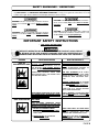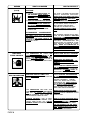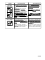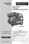
1
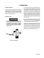
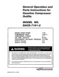
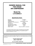
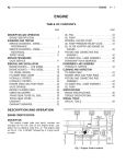
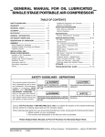
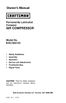
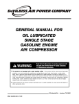
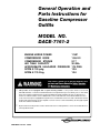
General Operation and
Parts Instructions for
Gasoline Compressor
Outfits
MODEL NO.
DACE-7161-2
ENGINE HORSE POWER
11HP
COMPRESSOR BORE
1.96/4.3
COMPRESSOR STROKE
2.17
AIR TANK CAPACITY
30 GAL.
APPROXIMATE UNLOADER PRESSURE 175 PSIG
SCFM @ 100 psig
12.5
SCFM @ 175 Psig
12.0
•
This product is not equipped with a spark arresting muffler. If the product will be used around
flammable materials, or on land covered with materials such as agricultural crops, forest, brush, grass, or other similar
items, then an approved spark arrester must be installed and is legally required in the state of California. It is a
violation of California statutes section 130050 and/or sections 4442 and 4443 of the California Public Resources
Code, unless the engine is equipped with a spark arrestor, as defined in section 4442, and maintained in effective
working order. Spark arresters are also required on some U. S. Forest service land and may also be legally required
under other statutes and ordinances.
•
Engine exhaust from this product contains chemicals known, in certain quantities, to cause cancer, birth defects or
other reproductive harm.
213 Industrial Dr. • Jackson, TN 38301
MGP-DAC-7161-2A 7/9/99
TABLE OF CONTENTS
Page No.
SAFETY PRECAUTIONS ................................................................................... 3-5
GENERAL INFORMATION .................................................................................... 6
COMPRESSOR DIAGRAM ................................................................................... 7
DESCRIPTION OF OPERATION ......................................................................... 6
INSTALLATION ................................................................................................ 8-10
Pre-Installation Inspection ................................................................................ 8
Vibration Mounting Kit (Stationary Compressor Outfits) .................................... 8
Location of the Compressor Outfit ................................................................ 8-9
Air Line Piping (Stationary Compressor Outfits) ........................................... 9-10
OPERATION ................................................................................................... 11-14
Operator Controls ..................................................................................... 11-12
Daily Startup Procedures .......................................................................... 13-14
Break-In Procedures ....................................................................................... 13
MAINTENANCE ............................................................................................. 14-17
Routine Maintenance Schedule ...................................................................... 14
Cleaning the Air Compressor Outfit ................................................................. 15
Checking and Changing Oil ............................................................................ 15
Checking and Changing Air Intake Filter .......................................................... 16
Draining Water from Air Tank ........................................................................... 16
Checking and Adjusting Belt Tension .............................................................. 17
SERVICE INSTRUCTIONS ............................................................................ 17-19
Replacing Drive Belt ................................................................................. 17-18
Engine Pulley and Flywheel Alignment ............................................................ 18
Check Valve Inspection and Cleaning ....................................................... 18-19
Servicing Intake and Exhaust Valves .............................................................. 19
TROUBLESHOOTING GUIDE ....................................................................... 20-24
Air Compressor Diagram & Parts List ........................................................ 26-27
Compressor Pump Diagram & Parts List ................................................... 28-29
WARRANTY ......................................................................................................... 30
SERVICE NOTES .................................................................................................. 31
ORDERING REPAIR PARTS ................................................................................ 32
PAGE 2
SAFETY GUIDELINES - DEFINITIONS
This manual contains information that is important for you to know and understand. This information relates to protecting YOUR SAFETY and PREVENTING EQUIPMENT PROBLEMS. To help you recognize this information, we use the
symbols to the right. Please read the manual and pay attention to these sections.
DANGER indicates an imminently hazardous situation
which, if not avoided, will result in death or serious
injury.
WARNING indicates a potentially hazardous situation
which, if not avoided, could result in death or serious
injury.
CAUTION indicates a potentially hazardous situation
which, if not avoided, may result in minor or moderate injury.
CAUTION used without the safety alert symbol indicates a potentially hazardous situation which, if not
avoided, may result in property damage.
IMPORTANT SAFETY INSTRUCTIONS
• SAVE THESE INSTRUCTIONS •
IMPROPER OPERATION OR MAINTENANCE OF THIS PRODUCT COULD RESULT
IN SERIOUS INJURY AND PROPERTY DAMAGE. READ AND UNDERSTAND ALL
WARNINGS AND OPERATING INSTRUCTIONS BEFORE USING THIS EQUIPMENT.
HAZARD
RISK OF
EXPLOSION OR FIRE
WHAT CAN HAPPEN
HOW TO PREVENT IT
GASOLINE AND GASOLINE VAPORS CAN
BECOME IGNITED BY COMING INTO CONTACT WITH HOT COMPONENTS SUCH AS
THE MUFFLER, FROM ENGINE EXHAUST
GASES, OR FROM AN ELECTRICAL SPARK.
TURN ENGINE OFF AND ALLOW IT TO
COOL BEFORE ADDING FUEL TO THE
TANK. EQUIP AREA OF OPERATION WITH
A FIRE EXTINGUISHER CERTIFIED TO
HANDLE GASOLINE OR FUEL FIRES.
COMBUSTIBLE MATERIALS WHICH COME
INTO CONTACT WITH HOT ENGINE PARTS
CAN BECOME IGNITED.
ADD FUEL OUTDOORS OR IN A WELL
VENTILATED AREA. MAKE SURE THERE
ARE NO SOURCES OF IGNITION, SUCH AS
CIGARETTES NEAR REFUELING LOCATION.
OPERATE COMPRESSOR IN AN OPEN
AREA AWAY FROM DRY BRUSH, WEEDS
OR OTHER COMBUSTIBLE MATERIALS.
STORE FUEL IN A SECURE LOCATION
AWAY FROM COMPRESSOR.
UNATTENDED OPERATION OF THIS PRODUCT COULD RESULT IN PERSONAL INJURY
OR PROPERTY DAMAGE.
RISK OF BURSTING
ALWAYS REMAIN IN ATTENDANCE WITH
THE PRODUCT WHEN IT IS OPERATING.
AIR TANK
THE FOLLOWING CONDITIONS COULD
LEAD TO A WEAKENING OF THE TANK, AND
RESULT IN A VIOLENT TANK EXPLOSION:
1. FAILURE TO PROPERLY DRAIN
CONDENSED WATER FROM THE TANK,
CAUSING RUST AND THINNING OF THE
STEEL TANK.
DRAIN TANK DAILY OR AFTER EACH
USE.
IF TANK DEVELOPS A LEAK,
REPLACE IT IMMEDIATELY WITH A NEW
TANK OR NEW COMPRESSOR OUTFIT.
2. MODIFICATIONS OR ATTEMPTED
REPAIRS TO THE TANK.
NEVER DRILL INTO, WELD, OR MAKE ANY
MODIFICATIONS TO THE TANK OR ITS
ATTACHMENTS.
PAGE 3
HAZARD
RISK OF BURSTING
(cont’d)
WHAT CAN HAPPEN
HOW TO PREVENT IT
AIR TANK
3. UNAUTHORIZED MODIFICATIONS TO
THE UNLOADER VALVE, SAFETY
VALVE, OR ANY OTHER COMPONENTS
WHICH CONTROL TANK PRESSURE.
THE TANK IS DESIGNED TO WITHSTAND
SPECIFIC OPERATING PRESSURES.
NEVER MAKE ADJUSTMENTS OR PARTS
SUBSTITUTIONS TO ALTER THE FACTORY SET OPERATING PRESSURES.
4. EXCESSIVE VIBRATION CAN WEAKEN
THE AIR TANK AND CAUSE RUPTURE OR
EXPLOSION. EXCESSIVE VIBRATION
WILL OCCUR IF THE COMPRESSOR IS
NOT PROPERLY MOUNTED OR IF THE
ENGINE OPERATES ABOVE RECOMMENDED RPM.
DO NOT REMOVE THE STIFFENER BAR
CONNECTING THE COMPRESSOR PUMP
TO THE ENGINE, EXCEPT TO ADJUST
BELT TENSION, THEN SECURELY
TIGHTEN THE STIFFNER BAR NUTS.
THIS BAR CONTROLS OUTFIT VIBRATION.
ATTACHMENTS & ACCESSORIES
RISK FROM
FLYING OBJECTS
EXCEEDING THE PRESSURE RATING OF
AIR TOOLS, SPRAY GUNS, AIR OPERATED
ACCESSORIES,
TIRES
AND
OTHER
INFLATABLES CAN CAUSE THEM TO EXPLODE OR FLY APART, AND COULD RESULT
IN SERIOUS INJURY.
FOR ESSENTIAL CONTROL OF AIR PRESSURE, YOU MUST INSTALL A PRESSURE
REGULATOR AND PRESSURE GAUGE
TO THE AIR OUTLET OF YOUR COMPRESSOR. FOLLOW THE EQUIPMENT MANUFACTURERS RECOMMENDATION AND
NEVER EXCEED THE MAXIMUM ALLOWABLE PRESSURE RATING OF ATTACHMENTS. NEVER USE COMPRESSOR TO
INFLATE SMALL LOW-PRESSURE OBJECTS SUCH AS CHILDREN’S TOYS,
FOOTBALLS, BASKETBALLS. ETC.
THE COMPRESSED AIR STREAM CAN
CAUSE SOFT TISSUE DAMAGE TO EXPOSED SKIN AND CAN PROPEL DIRT,
CHIPS, LOOSE PARTICLES AND SMALL
OBJECTS AT HIGH SPEED, RESULTING IN
PROPERTY DAMAGE OR PERSONAL INJURY.
ALWAYS WEAR ANSI Z87.1 APPROVED
SAFETY GLASSES WITH SIDE SHIELDS
WHEN USING THE COMPRESSOR.
NEVER POINT ANY NOZZLE OR
SPRAYER TOWARD ANY PART OF THE
BODY OR AT OTHER PEOPLE OR
ANIMALS.
ALWAYS TURN THE COMPRESSOR OFF
AND BLEED PRESSURE FROM THE AIR
HOSE AND TANK BEFORE ATTEMPTING
MAINTENANCE, ATTACHING TOOLS OR
ACCESSORIES.
RISK TO BREATHING
PAGE 4
BREATHING EXHAUST FUMES FROM
ENGINE WILL CAUSE SERIOUS INJURY OR
DEATH.
ALWAYS OPERATE AIR COMPRESSOR
IN A CLEAN, WELL VENTILATED AREA.
AVOID ENCLOSED AREAS SUCH AS
GARAGES, BASEMENTS, STORAGE
SHEDS, ETC., WHICH LACK A STEADY
EXCHANGE OF AIR. NEVER OPERATE
UNIT IN ENCLOSED LOCATIONS
OCCUPIED BY HUMANS OR ANIMALS.
KEEP CHILDREN, PETS AND OTHERS
AWAY FROM AREA OF OPERATION.
THE COMPRESSED AIR FROM YOUR
COMPRESSOR IS NOT SAFE FOR BREATHING! THE AIR STREAM MAY CONTAIN
CARBON MONOXIDE, TOXIC VAPORS OR
SOLID PARTICLES FROM THE TANK.
NEVER INHALE AIR FROM THE COMPRESSOR EITHER DIRECTLY OR FROM A
BREATHING DEVICE CONNECTED TO THE
COMPRESSOR.
SPRAYED MATERIALS SUCH AS PAINT,
PAINT SOLVENTS, PAINT REMOVER, INSECTICIDES, WEED KILLERS, ETC.. CONTAIN
HARMFUL VAPORS AND POISONS.
WORK IN AN AREA WITH GOOD CROSSVENTILATION. READ AND FOLLOW THE
SAFETY INSTRUCTIONS PROVIDE ON
THE LABEL OR SAFETY DATA SHEETS
FOR THE MATERIAL YOU ARE SPRAYING. USE A NIOSH/MSHA APPROVED
RESPIRATOR DESIGNED FOR USE WITH
YOUR SPECIFIC APPLICATION.
HAZARD
RISK FROM
MOVING PARTS
WHAT CAN HAPPEN
THE ENGINE CAN START ACCIDENTALLY
IF THE FLYWHEEL IS TURNED BY HAND OR
MOVED BY PULLING ON THE STARTER
ROPE.
ALWAYS DISCONNECT THE SPARK
PLUG AND BLEED PRESSURE FROM
THE TANK BEFORE PERFORMING
MAINTENANCE.
MOVING PARTS SUCH AS THE PULLEY,
FLYWHEEL AND BELT CAN CAUSE
SERIOUS INJURY IF THEY COME INTO
CONTACT WITH YOU OR YOUR CLOTHING.
NEVER OPERATE THE COMPRESSOR
WITH GUARDS OR COVERS WHICH ARE
DAMAGED OR REMOVED.
ATTEMPTING TO OPERATE COMPRESSOR WITH DAMAGED OR MISSING PARTS
OR ATTEMPTING TO REPAIR COMPRESSOR WITH PROTECTIVE SHROUDS
REMOVED CAN EXPOSE YOU TO MOVING
PARTS AND CAN RESULT IN SERIOUS
INJURY.
RISK OF BURNS
HOW TO PREVENT IT
ANY REPAIRS REQUIRED ON THIS PRODUCT SHOULD BE PERFORMED BY
AUTHORIZED SERVICE CENTER PERSONNEL.
TOUCHING EXPOSED METAL SUCH AS THE
COMPRESSOR HEAD OR OUTLET TUBES OR
CONTACT WITH HOT ENGINE PARTS SUCH
AS THE MUFFLER CAN RESULT IN SERIOUS
BURNS.
NEVER TOUCH ANY EXPOSED METAL
PARTS ON ENGINE OR COMPRESSOR
DURING OR IMMEDIATELY AFTER OPERATION. ENGINE AND COMPRESSOR WILL
REMAIN HOT FOR SEVERAL MINUTES
AFTER OPERATION.
THE GASOLINE ENGINE , THE ENGINE
MUFFLER, THE COMPRESSOR HEAD AND
TUBING BECOME VERY HOT DURING
OPERATION.
DO NOT REACH AROUND PROTECTIVE
SHROUDS OR ATTEMPT MAINTENANCE
UNTIL UNIT HAS BEEN ALLOWED TO COOL.
PAGE 5
GENERAL INFORMATION
You have purchased a complete compressor outfit consisting of an air compressor, ASME approved air tank,
gasoline engine, and associated controls and instruments. The compressor outfit you have selected is a
two stage stationary outfit.
Your new compressor can be used for operating paint
sprayers, air tools, grease guns, air brushes, caulking
guns, and sand blasters, spraying weed killer and
insecticides, etc. An air pressure regulator may be
necessary for some of these
applications. Refer to Figure 1 for a photograph of
the compressor and to identify the major components
of the compressor.
A regularly scheduled program of preventive maintenance is necessary to insure the long life that has been
designed into your DeVilbiss compressor outfit. This
instruction manual, along with regular maintenance
will maintain your compressor outfit in good working
order. Before operating or performing any maintenance
on your outfit, refer to these publications.
DESCRIPTION OF OPERATION
The gasoline engine uses a pulley and drive belt to
drive the compressor flywheel. The flywheel turns the
compressor crankshaft causing the up and down movement of the pistons in the cylinder; this up and down
movement draws and compresses the air.
On the down stroke of the piston, air is drawn in through
the air intake. The exhaust valves remain closed. On
the up stroke of the piston, both the valves are closed
and air is compressed in the cylinder. As pressure
builds in the cylinder the exhaust valve opens and the
compressed air is forced out of the cylinder through
the check valve and into the air tank. This process
continues until the air pressure reaches maximum tank
pressure.
Working air pressure becomes available when the compressor has raised the tank pressure above that required at the air discharge valve. The air intake must
be kept clear of all obstructions which could interfere
with air delivery to the compressor.
All gasoline compressor outfits are continuously running outfits controlled by tank pressure. At maximum
PAGE 6
tank pressure the unloader valve exhausts air to atmosphere (blowoff); tank pressure closes the check
valve retaining air pressure inside the tank. When tank
pressure drops to a pre-determined pressure, the
unloader valve closes, and air pressure opens the
check valve allowing compressed air into the tank. As
maximum tank pressure is reached, if the unloader
valve malfunctions and compressed air is not exhausted at or near its blowoff setting, the air tank safety
valve will protect the air tank against high pressure by
popping at its factory set pressure. The safety valve
popping pressure is slightly higher than the unloader
valve blowoff pressure.
This compressor outfit is equipped with a gas saving
throttle control device. When maximum tank pressure
is reached and the unloader valve opens the throttle
control is also activated, The throttle control holds the
engine at a factory set idling speed until air pressure
in the tank drops to reset or minimum tank pressure.
At reset pressure when the unloader valve closes the
throttle control is reactivated and the engine accelerates to full throttle.
Gas
Engine
Pump
Air Intake
Filter
Engine Oil
Dipstick
Fuel
Tank
Belt
Guard
Two-Stage
Pump
Engine Air
Filter
Pump Oil
Fill Plug
Engine Oil
Drain
(Not Shown)
Throttle
Control
Pump Oil
Sight Glass
Unloader
Pump Oil
Drain Plug
Safety
Valve
Pressure
Gauge
Drain Valve
(Not Shown)
Air Outlet For
Discharge
Valve
Figure 1 - Typical Gasoline Compressor Outfit
PAGE 7
INSTALLATION
PRE-INSTALLATION INSPECTION
NOTE
Each air compressor outfit is carefully checked before shipment. With
improper handling, damage may
result in transit and cause problems
in compressor operation; a bent
crankshaft, etc.
2. Insert the vibration mounts in the mounting holes.
Place a flat washer under the mounting surface
and secure each mount with a lockwasher and
nut. See Figure 3.
Immediately on equipment arrival, check for both concealed and visible damages to avoid expenses being
incurred to correct such problems. This should be done
regardless of any visible signs of damage to the shipping container. Report any damages to carrier and arrange for inspection of goods immediately.
VIBRATION MOUNTING KIT
(Stationary Compressor Outfits)
Figure 3 - Installation of Vibration Mounting Kit
Bolting legs to a stiff surface can
cause tank rupture resulting in serious
injury or damage. Do not permanently
mount compressor to any surface without using the vibration mount kit.
Portable compressor outfits may be permanently
mounted in one location such as a truck bed, if desired. A vibration mount kit is included with the outfit
for this purpose.
1. In order to maintain adequate ventilation for
compressor cooling and to avoid contact with
pick-up truck bed, always mount the outfit at
least 8 inches from any vertical wall. Using the
holes in the air tank support legs as a guide,
mark and drill four 5/16 inch diameter holes in
the mounting surface.
To prevent excessive vibration which
may cause tank rupture or explosion,
never remove the engine stiffener bar
or increase the engine RPM. Make
sure the engine bolts and stiffener bar
nuts are tight. Do not operate the outfit
if the rubber feet are not attached.
PAGE 8
3. Set the outfit on top of the vibration mounts
(the exposed threaded ends) and secure
each mount to the air tank legs with lock
washer and nut.
LOCATION OF THE COMPRESSOR
OUTFIT
Engine exhaust contains toxic carbon
monoxide. Operate the engine in a well
ventilated area only. If inhaled, it can
cause dizziness, unconsciousness and
possibly death.
The air compressor outfit should be located as close
as possible to the point where the compressed air is
to be used. The area selected should be dry, clean,
cool, and well ventilated. Make certain that the outfit
is mounted level on a solid foundation so no strain is
imposed on the support feet or base. Keep the outfit
away from areas which have dirt, vapor, and volatile
fumes in the atmosphere which may clog and gum
the intake filter and valves causing inefficient
operation. Where this not practical a remote air
intake is recommended.
NOTE
Where a remote air intake is used, enlarge
the side of the air intake piping by one pipe
size for each 10 feet of length.
Pipe thread sealant must be used on all threads, and
all joints are to be made up tight, since small leaks in
the piping system are the largest single cause of high
operating costs.
Stationary outfits must be bolted or lagged to the floor
to prevent movement. When lagging down, leave a minimum of 1/8 inch between the bolt and support feet.
The use of vibration pads at each support foot is required to eliminate the possibility of tank rupture.
All piping should be sloped to an accessible drain
point and all outlets should be taken from the top of
the main distribution air line so that moisture cannot
enter the outlet.
The flywheel side of the outfit should be placed toward
the wall and protected with a totally enclosed belt
guard. In no case should the flywheel be closer than
12 to 18 inches from the wall or other obstruction that
will interfere with the flow of air through the fan blade
flywheel. See Table 1 for recommended distances. The
area should allow space on all sides for air circulation
and for ease of normal maintenance.
The compressor outfit must not be operated in any confined area where
heat from the outfit can not readily escape. Damage to the outfit may result.
The main distribution air line should not be smaller
than the compressor air discharge valve outlet. A
smaller line will restrict the flow of air. For long air
lines, refer to Table 2, Pipe Sizes for Compressed
Air Lines, for recommended pipe sizes. It is recommended that a flexible coupling be installed between
the air discharge valve outlet and main air distribution line to allow for vibration.
To remove entrained dirt, oil and water, install separator in the main distribution line, a sufficient distance
from the compressor. This will allow the air to cool to
room temperature before passing through the separator.
Additional separators or filter may be used depending on the application.
The compressor crankcase and head are designed
with fins which allow for proper cooling. Clean or blow
off the fins and any other parts of the compressor outfit that collect dust or dirt. A clean compressor runs
cooler and provides longer service. Do not place rags,
containers, or other material in or against the belt guard
which will obstruct ventilation openings necessary for
proper compressor operating temperatures.
AIR LINE PIPING
(STATIONARY COMPRESSOR OUTFITS)
NOTE
For underground installation, bury air
lines below the frost line and avoid
pockets where condensation can
gather and freeze. Apply pressure before underground lines are covered
to make sure all pipe joints are free
from leaks.
Table 2 Pipe Sizes for Compressed Air Lines
AIR
The use of plastic pipe, soldered joint,
or failure to insure system capability
of flex joints and flexible hose can
result in mechanical failure, property
damage, and serious injury.
Plastic or PVC pipe is not designed for
use with compressed air. Regardless
of its indicated pressure rating, plastic
pipe can burst from air pressure. Use
only metal pipe for air distribution lines.
A typical compressed air distribution system as shown
in Figure 4, page 10 should be of sufficient pipe size
to keep the pressure drop between the supply and
point of use to a minimum. All pipes and fittings used
must be certified safe for the pressures involved.
cfm
1-5
10
15
20
25
30
35
40
50
60-70
80-100
LENGTH OF PIPE LINES IN FEET
25
50
1/2
1/2
1/2
3/4
3/4
3/4
3/4
3/4
1
1
1-¼
1/2
1/2
3/4
3/4
3/4
3/4
3/4
1
1
1
1-¼
75
100
150
200 250 300
1/2
1/2
3/4
3/4
3/4
3/4
1
1
1
1
1-¼
1/2
1/2
3/4
3/4
3/4
1
1
1
1
1
1-¼
1/2
1/2
3/4
3/4
1
1
1
1
1
1-¼
1-½
1/2
1/2
3/4
3/4
1
1
1
1
1
1-¼
1-½
1/2
1/2
3/4
3/4
1
1
1
1
1
1-¼
1-½
1/2
1/2
3/4
3/4
1
1
1
1
1
1-¼
1-½
Pipe sizes are in inches
PAGE 9
Figure 4. Typical Compressed Air Distribution System
PAGE 10
OPERATION
Operator Controls
The unloader valve for the operation of the gasoline
compressor outfit is located between the compressor
pump and gasoline engine. The air discharge valve
can be located on the end of the air tank. The safety
valve and pressure gauge are attached to the tank
below the unloader. See page 7.
Unloader Valve
Pressure loads beyond the design limits
may cause tank rupture or explosion. Do
not attempt to adjust, remove, or defeat
the unloader valve, or change and modify
any pressure control device. If replacement is necessary, the same rated valve
must be used.
The unloader valve, Figure 6, is controlled by tank pressure. Compressors with unloaders run continuously
and maintain air pressure within set limits. At maximum tank pressure the unloader valve opens and the
compressed air is exhausted to atmosphere. This
prevents the compressor from continually building more
pressure if air is not needed. When the tank pressure
drops to a predetermined minimum pressure, the
unloader valve closes and the compressor again builds
up the tank pressure. Pressure continues to build until maximum tank pressure is achieved. The cycle
then repeats itself.
The unloader is used because frequent start-ups and
stops are impractical with a gasoline engine. The
unloader valve is preset at the factory. Never attempt
to make adjustments to the unloader valve.
The toggle lever on the front of the unloader valve should
be pulled out or in the horizontal position when starting up the compressor. This prevents the compressor
from starting under load. Once the engine has reached
full throttle, the lever should be pushed to the side,
returning it to its original position to allow the compressor pump to build pressure in the air tank.
Toggle
Lever
Figure 6. Unloader Valve
PAGE 11
The unloader then reactivates the throttle control
and accelerates the engine to full throttle.
Over-pressurization of the air tank
may cause tank rupture or explosion.
The air tank is protected from overpressurization by a safety valve. Do
not eliminate, make adjustments or
substitutions to this device. Occasionally pull the ring on the safety valve
to make sure it operates freely. If it
doesn’t, the safety valve must be
replaced. Innercooler safety valves
used on two stage outfits must be
similarly checked.
The safety valve, Figure 7, is set at the factory to be
pressure approximately 15 pounds higher than the
rated pressure of the outfit. If the unloader valve malfunctions and does not exhaust compressed air automatically at maximum tank pressure the safety valve
will protect the air tank against excessive air pressure
by popping off at its preset pressure.
Two stage compressors with unloader controls will have
a safety valve on the intercooler, set 50 to 55 pounds.
The purpose of this safety valve is to prevent the full
tank pressure building up in the large, low pressure
cylinder or intercooler.
THROTTLE CONTROL
A gas saving throttle control has been incorporated
on some compressor outfits. During normal operation,
as maximum tank pressure is obtained, the unloader
exhausts compressed air and activates the throttle
control of the engine. The throttle control holds the
engine at a factory set idling speed until air pressure
in the tank drops to reset or minimum tank pressure.
ADDITIONAL REGULATORS AND
CONTROLS
Since the air tank pressure is usually greater than
that which is needed, a separate regulator is usually
employed to control the air pressure ahead of any
individual air driven device.
The gasoline engine and air compressor
pumps on all compressor outfits are
shipped without oil. Do not attempt to
operate for any reason without first adding oil to the engine and compressor
pump crankcase. Serious damage can
result from even very limited operation
unless filled with oil and broken in
correctly. Make sure to closely follow the
initial startup procedures.
NOTE
The compressor outfit should be placed
on a level surface in a dry, clean, well
ventilated, area. Do not place any material on or against the belt guard. This
blocks ventilator openings necessary for
proper compressor cooling.
1. Remove the oil fill plugs on the gasoline engine
and air compressor pump and slowly add oil
until the units are full. Refer to the “Gasoline
Engine Owners Manual” for recommended oils
and fill capacities for the engine. The compressor pump holds approximately 60 fluid oz..
TWO STAGE COMPRESSOR UNITS
Viscosity Chart
Figure 7. Safety Valve
Recommended Oil
(API SG/CD Heavy Duty)
Room or Ambient
Temperature
SAE20
SAE30
Below 20ºF
Above 32ºF
Crankcase capacity equals approximately 60 fluid
ounces.
2. The air compressor outfit is ready for use.
PAGE 12
3. Periodically check the compressor outfit during
the first few days of operation to make sure
the compressor outfit is running smoothly and
all controls are operating properly.
NOTE
After the compressor has been in
operation for 2 to 3 hours, tighten the
compressor head bolts.
Torque two stage compressor head
bolts to 35 foot-pounds using a crisscross pattern when tightening.
BREAK-IN PROCEDURES
Perform steps 1-8 of the Daily Startup Procedures.
Open the air discharge valve.
DAILY STARTUP PROCEDURES
Perform the following checks before starting the
compressor outfit.
1. Ensure that nothing is blocking the belt
guard air openings.
2. Pull the ring on the safety valve to make
sure the valve moves freely and smoothly.
4. Check the engine fuel tank level. Add fuel if
necessary.
Before starting the compressor outfit, check the
following:
5. Close the air discharge valve.
6. Set the toggle lever of the unloader valve in
the vertical position to relieve compressor
head pressure.
7. Move the control lever or choke lever to the
CHOKE position.
8. Turn the engine lever or key switch to the
ON position.
NOTE
If the engine is warm or the air temperature is high, move the control
lever or choke lever away from the
CHOKE position as soon as the engine
starts.
9. Start the compressor outfit by pulling the
starter handle or by depressing the starter
button. Return the toggle lever on the unloader
valve to the horizontal position and allow
outfit run for 10 minutes without building any
pressure. Check that the unloader exhausts
air at maximum tank pressure.
3. Check the engine and compressor oil levels.
Add oil if necessary.
If these break-in procedures are not
followed, premature pump failure may
result and void your warranty.
Gasoline is extremely flammable and
explosive. Refuel in a well ventilated
area with engine stopped. Allow engine
to cool before refueling.
Do not smoke or allow flames or sparks in
the area where the engine is refueled or
where gasoline is stored.
Do not overfill the tank and make sure
the filler cap is securely closed after
refueling. Be careful not to spill fuel
when refueling. Fuel vapor or spilled
fuel may ignite. If any fuel is spilled,
make sure the area is dry before
starting the engine.
10. Check the following:
a. Make sure all controls are operating
correctly. Refer to the "Operator Controls"
section of this manual. A separate
gasoline engine instruction manual is
provided detailing engine operation.
b. Check all air lines, fittings and pipes for
leaks. Even minor leaks can cause the
compressor to overwork resulting in
premature breakdown or unsatisfactory
performance.
PAGE 13
c. Check for excessive vibration and noise.
Correct any defects found.
2. Turn the engine lever or key switch to the OFF
position.
d.
3. Close the air discharge valve.
Check for oil leaks. Correct any leaks
found.
4. Remove air tool or accessory.
SHUT DOWN PROCEDURES
To stop the engine in an emergency, turn the engine
ON/OFF lever or key switch to the OFF position. Under normal conditions, use the following procedures.
5. Open outlet valve or regulator to allow air to
slowly bleed from the tank. Close the outlet
valve or regulator when the tank pressure is
approximately 20 psig.
6. Drain water from tank.
1. Allow the tank pressure to build to maximum
and the engine to throttle down to idle speed.
MAINTENANCE
To ensure efficient operation and longer life of the air
compressor outfit a routine maintenance schedule
should be prepared and followed. The following routine maintenance schedule is geared to an outfit in a
normal working environment operating on a daily basis. If necessary , the schedule should be modified to
suit the conditions found with your compressor outfit.
The modifications will depend upon the hours of operation and the working environment. Compressor
outfits in an extremely dirty and/or hostile environment
will require a greater frequency of all maintenance
checks. The maintenance label mounted on the air
tank also lists the required maintenance checks.
For additional maintenance instructions, recommended
oil and fuel on the gasoline engine, refer to "Gasoline
Engine Owners Manual".
ROUTINE MAINTENANCE SCHEDULE
NOTE
Drain and refill the compressor pump
crankcase after the first 100 hours of
operation. Add approximately 60 oz..
to pump.
Drain and refill the gasoline engine crankcase
after the first 20 hours of operation. See “Gasoline
Engine Owners Manual” for engine crankcase
capacity.
2. Drain water from the air tank and any
moisture separators or transformers.
3. Check for any unusual noise and/or vibration.
4. Manually check the safety valve to make sure
it is operating properly.
5. Check the condition of the air cleaner on the
gasoline engine. Clean and/or replace as
necessary.
DAILY
6. Check the gasoline engine's fuel level. Add fuel
if necessary.
1. Check the gasoline engine and air compressor
pump oil levels; add if necessary.
7. Inspect for oil leaks and repair any leaks found.
PAGE 14
WEEKLY
1. Clean and inspect the compressor air
intake filter; replace if necessary.
2. Inspect condition of drive belt; replace if
necessary.
3. Clean outside parts of the compressor as well as
the engine in order to maintain efficient cooling.
MONTHLY
CLEANING THE AIR COMPRESSOR
OUTFIT
The external components of the compressor outfit
should be cleaned at least once a week. The air compressor crankcase and head are designed with fins
which allow for proper cooling. Clean or blow off fins
and any other parts of the outfit that collect dirt or
dust. A clean compressor runs cooler and provides
longer service.
CHECKING AND CHANGING OIL
1. Check the alignment of the engine pulley to the
flywheel if necessary, align to within 1/16 inch.
2. Inspect for and correct any oil leaks.
3. Check drive belt tension adjust if necessary.
4. Inspect air lines and fittings for leaks; correct as
necessary.
EVERY 50 HOURS OF OPERATION
1. Clean the gasoline engine air cleaner.
Overfilling with oil will cause premature
air compressor failure. Do not overfill.
1. Check oil level in compressor crankcase
before each use.
For two stage compressors the oil level should
be to the middle of the oil sight glass.
NOTE
The compressor pump oil must be
changed after the first 100 hours of
operation.
EVERY 100 HOURS OF OPERATION
Changing Oil:
1. Drain and refill the gasoline engine crankcase
with clean oil.
1. Remove the oil fill and drain plugs. Collect the oil
in a suitable container.
2. Clean and set gap or replace spark plug.
2. Replace the oil drain plug and refill the crankcase
with recommended oil. Refer to page 14 of this
manual for recommended compressor oil.
3. Clean fuel sediment cup.
EVERY 500 HOURS OF OPERATION
1. Drain and refill compressor crankcase with clean
oil.
EVERY 2000 HOURS OF OPERATION, OR IF
A PROBLEM IS SUSPECTED
NOTE
It is important to maintain the proper
oil level. A low oil level reduces
proper cylinder wall lubrication and
increases ring wear.
3. Replace the oil fill plug.
4. Start the engine and run the compressor outfit
for several minutes. Shut the compressor down
and check the oil level. If necessary add more
oil.
1. Check condition of compressor pump intake
and exhaust valves. Replace if damaged or
worn out.
PAGE 15
CHECKING AND CHANGING AIR
INTAKE FILTER
NOTE
Keep the air filter clean at all times. Do
not operate compressor outfit when
the filters are removed.
The condition of the air intake filter should be checked
once a week. A dirty air intake filter will not allow the
compressor to operate at full capacity and will increase
oil usage.
When the air filter becomes dirty, oily, or covered with
paint overspray it must be replaced. To check and/or
replace the air intake filter, remove the screw securing
the filter assembly to the air compressor pump. Remove the filter. Inspect condition of filter; replace if
necessary.
NOTE
Felt and foam intake filters can be
washed in non-explosive solvent.
Allow to dry and reinstall. DO NOT OIL
INTAKE FILTERS.
DRAINING WATER FROM AIR TANK
Water will condense in the air tank.
If not drained, the water will corrode
and weaken the air tank. A weakened
tank may explode or rupture causing
personal injury. Drain the tank as
instructed below.
Water should be drained from the air tank daily. If
humidity is high the tank should be drained at regular
intervals during the day. Operate the compressor
outfit to allow 15 to 20 psi air pressure in the tank.
PAGE 16
Open the drain valve. Continue operating outfit until
all moisture is removed from the tank. Close the drain
valve tightly.
NOTE
If the draincock is clogged, release
the air pressure in the tank. Remove
the drain valve and clean or replace.
Apply sealant to the threads before
reinstalling the drain valve.
CHECKING AND ADJUSTING BELT
TENSION
Serious injury or damage may occur
if parts of the body or loose items get
caught in moving parts. Never operate
the compressor outfit with the belt
guard removed. The belt guard should
only be removed after the spark plug
wire has been disconnected.
The drive belt should be kept in proper tension as a
loose belt will slip and wear faster. An over tightened
belt will place an excessive load on the engine and
compressor pump bearings causing premature failure. The belt tension should be checked as follows:
1. Disconnect the spark plug wire and drain all air
pressure from the air tank.
2. Remove the belt guard.
3. Loosen all engine mounting hardware and slide
the engine either toward or away from the
compressor until correct belt tension is
achieved.
4.
Hold the belt tension until the engine mounting hardware can be tightened.
5.
Ensure that the belts are centered on the
engine pulley and compressor flywheel.
NOTE
Once the engine has been moved
from its factory set location the engine
pulley must align to within 1/16 inch
to the compressor flywheel.
Figure 8. Checking Belt Tension
6.
Torque engine mounting bolts to 20 +3
foot pounds.
7.
Reinstall the belt guard.
8.
Connect the spark plug wire.
On compressors equipped with standard V-belts,
each belt should deflect 1/4” at the midway point
between the engine pulley and flywheel when a
downward force of 4 pounds, or equivalent finger
pressure, is applied at the midway point. Refer to
Figure 8.
SERVICE
INSTRUCTIONS
Moving parts, unexpected engine start-up and compressed air can cause serious injury.
Always disconnect the spark plug wire and relieve pressure from the air tank before
performing any of these service procedures. Never operate the air compressor with the
belt guard removed.
REPLACING DRIVE BELT
The gasoline engine is mounted to the tank assembly saddle. By loosening engine mounting hardware,
the engine can be moved to allow for easy removal
of the belt. Replace the drive belt as follows:
1. Disconnect the spark plug wire and drain all air
pressure from the tank.
2. Remove the belt guard.
3. Loosen the engine mounting hardware and
slide the engine toward the compressor.
4. Remove the belt and replace with a new one.
On compressor outfits with matched Vbelts, both belts must be replaced at the same
time.
NOTE
The belts should be centered on
the flywheel and engine pulley. Once
the engine has been moved from its
factory set location, the engine
pulley must align to within 1/16
inch of the flywheel.
PAGE 17
REPLACING DRIVE BELT (cont’d)
6. Reinstall the drive belt. Make sure the belt
is centered on the engine pulley and flywheel.
5. Slide the engine back into its original position
and adjust the belt tension, Figure 8.
7. Slide the engine back into its original position
and adjust the belt tension, Figure 8.
For compressors equipped with standard V-belts,
the proper tension for each belt is approximately
1/4 inch belt deflection measured midway between
the engine pulley and flywheel when a 4 pound
downward force, or equivalent finger pressure, is
applied at that point.
For compressors equipped with poly-V-belts, the
proper tension is approximately 1/4 inch belt
deflection measured midway between the engine
pulley and flywheel when a 3 pound downward
force, or equivalent finger pressure, is applied at
that point.
6.
Hold the belt tension until the engine mounting
hardware can be tightened.
7.
Torque engine mounting bolts to 20 +3 footpounds.
8.
Reinstall the belt guard.
For compressors equipped with standard V-belts
the proper tension for each belt is approximately
1/4 inch belt deflection measured midway between
the engine pulley and flywheel when a 4 pound
downward force, or equivalent finger pressure, is
applied at that point.
9.
Connect the spark plug wire.
8. Hold the belt tension until the engine mounting hardware can be tightened.
9. Torque the engine mounting bolts to 20 +3 footpounds.
ENGINE PULLEY AND FLYWHEEL
ALIGNMENT
The engine pulley and flywheel must be aligned to
prevent excessive wear of the drive belt and to keep
the belt from coming out of the pulley and flywheel
grooves. Align the belts as follows:
Serious injury or damage may occur if
parts of the body or loose items get
caught in moving parts. Never operate
the compressor outfit with belt guard
removed. Remove belt guard only after
the spark plug had been disconnected.
1.
Disconnect the spark plug wire and drain
all pressure from the air tank.
2.
Remove the belt guard.
3. Loosen all engine mounting hardware and
slide the engine toward the compressor. Remove the drive belt.
10. Reinstall the belt guard.
11. Connect the spark plug wire.
CHECK VALVE INSPECTION AND CLEANING
Remove and inspect the check valve at least once a
year and more often if the compressor is heavily
used. Moisture and other contaminates in the hot
compressed air will cause an accumulation of
carbon-like residue on the working parts. If the valve
has heavy carbon build-up, it should be replaced.
Use the following procedure to inspect, clean, or
replace the check valve:
1. Disconnect the spark plug wire and release all air pressure from the air tank.
2. Loosen the top and bottom tube nuts
and remove the outlet tube.
3. Unscrew the check valve (counterclockwise) from the air tank using a socket
wrench.
4. Loosen the engine pulley set screw and move
the pulley toward or away from the engine until
the pulley aligns with the flywheel within 1/116
inch.
4. Check that the valve and disc moves freely
inside the check valve and that the spring
holds the disc in the upper closed position.
The check valve may be cleaned with a
solvent.
5. Torque the engine pulley set screw to 75 +5
inch-pounds.
5. Apply pipe sealant to the check valve threads.
PAGE 18
6. Reinstall the check valve. DO NOT OVERTIGHTEN.
SERVICING INTAKE AND EXHAUST VALVES
The intake and exhaust valves as well as the valve
plates and cylinder head will, over a period of time
accumulate residue of carbon-like material on their
surfaces. The material will decrease the efficiency
of the compressor. These components should be
inspected, whenever a problem is suspected, and
cleaned or replaced with new parts. Use the following procedure to inspect the parts.
Many solvents are highly flammable
and a health hazard if inhaled. Always
observe the solvent manufacturers
safety instructions and warning.
e. Clean carbon deposits in head cavities and
valves plates with lacquer thinner or
other suitable solvent.
f.
Remove the intake and exhaust valve
assemblies from the valve plate. Clean and
inspect the valves, and valve retainers.
Replace any defective components as
necessary.
g. Reassemble the intake and exhaust
valves.
During service or repair activities
always disconnect the spark plug wire
before attempting repair maintenance
on compressor outfit. Make sure the
pressure is released from the air tank.
NOTE
Do not use gasket cement on any
gasket surface as this may clog the
compressor valve cavities and flow
areas.
1. Disconnect the spark plug wire and drain
all air pressure from the air tank.
h. Reinstall the valve plate. Use a new
valve plate gasket.
2. Service two stage compressor valves
as follows:
a. Remove the screws securing the
intercooler to the cylinder head and
remove the intercooler.
i.
Install the cylinder head. Use a new
head gasket. Snug the mounting screws
tight then torque to 35 foot-pounds
using a criss cross pattern when torquing.
j.
Install a new after cooler gasket. Secure
the aftercooler with the mounting screws
removed.
b. Disconnect the outlet line from the
aftercooler.
c. Remove the screws securing the
aftercooler to the cylinder head and
remove the aftercooler.
d. Remove the hardware securing the
cylinder head and remove the
cylinder head and valve plate.
k. Connect the outlet line to the aftercooler.
l.
Install new intercooler gaskets and
secure the intercooler with the mounting
screws removed.
4. Connect the spark plug wire.
PAGE 19
TROUBLESHOOTING
GUIDE
Performing service checks or repairs may expose moving parts, or compressed air sources.
Personal injuries may occur. Prior to attempting any service check or repairs, remove the
spark plug wire and bleed off all air pressure. Never operate the outfit with the belt guard
removed. Repairs should be preformed by an Authorized Service Center personnel only.
TROUBLESHOOTING CHART
PROBLEM
Gasoline Engine will not run.
(Consult the "Gasoline Engine
Owners Manual" for
Manufacturer's Service Centers
for warranty, repairs and service
parts.)
CAUSE
CORRECTION
The gasoline tank is empty.
Fill the tank with gas.
The choke is not set properly.
Reset the choke. Remember, a
warm engine requires less
choking than a cold engine.
Improper fuel mixture.
Adjust the fuel mixture.
The unloader valve toggle lever is
in a horizontal position.
Place unloading valve toggle lever
in a vertical position.
If any fuel is spilled, make
sure the area is dry before
testing the engine. Fuel
vapor or spilled fuel may
may ignite.
PAGE 20
No spark from the spark plug.
Remove the spark plug, clean
and adjust gap or replace.
Spark plug disconnected.
Connect spark plug.
TROUBLESHOOTING CHART (Continued)
PROBLEM
Rough Operation of Gasoline
Engine. (Consult the "Gasoline
Engine Owners Manual" for
Manufacturer's Service Center for
warranty, repairs and service
parts.)
CAUSE
CORRECTION
Clogged fuel line.
Clean.
Water in fuel.
Be sure outfit is adequately
protected from the elements so
as to prevent water seeping into
system.
Faulty choke control.
Adjust. See engine
manufacturer's instructions
included with engine.
Improper fuel mixture.
Use only fuel recommended by
engine manufacturer. See
manufacturer's instructions.
Loose ignition system connections.
Check all connections to insure
tightness.
Air leaks in carburetor or manifold connections.
Check to be sure all connections
are tight.
Restricted air intake
Clean filter or properly size pipe
to the remote intake.
Air leaks in system.
Check for source of leak and
correct.
Undersized unit for air requirement.
Replace with larger unit or
purchase a second outfit.
Worn or carbonized valves.
Replace.
Flywheel wobbles.
Set screw or bolt not tight
enough.
Tighten.
Air leaks.
Tube fittings loose.
Tighten fittings with audible leak
and check fittings under pressure
with soapy water solution.
Leak at welds
Replace air tank.
Insufficient air and too much
compressor "ON" time.
Do not drill into, weld or otherwise modify air tank or tank will
be weakened. Tank must be
replaced.
If safety valve or unloader valve
replacement is necessary, a part
with the same rating must be
used.
PAGE 21
TROUBLESHOOTING CHART (Continued)
CAUSE
PROBLEM
Air leaks (cont)
Low Discharge Pressure
Knocking
PAGE 22
CORRECTION
Air leak in safety valve.
Operate safety valve manually by
pulling on ring. If valve still leaks, it
should be replaced.
Defective check valve.
(Unloader valve)
A defective check valve results in a
constant air leak, back through the
unloader valve when there is pressure
in the air tank and the compressor is
not running. Turn the engine off; move
the unloader valve toggle lever to the
vertical position. If air leaks out of the
tank through the unloader valve, clean
or replace the check valve. (DO NOT
OVERTIGHTEN).
Prolonged excessive use of air.
Decrease amount of air usage.
Restricted check valve.
Remove and clean, or replace.
Restricted air intake filter.
Clean or replace air intake filter.
Air leaks.
Tighten fittings.
Hole in hose or air piping.
Check and replace if required.
Faulty pump.
Repair or replace.
Loose pulley.
Tighten pulley set screw.
Low oil level (compressor pump
and/or gasoline engine).
Check oil level and maintain at
prescribed level.
Restricted check valve.
Remove and clean or replace.
Wrong oil used.
Follow oil recommendations listed
in the "Gasoline Engine Owners
Manual".
Compressor and/or engine bolts
loose.
Check all bolts and tighten as
required.
Excessive carbon deposits in head.
Remove the head and valve plate.
Clean top of piston and bottom of
valve plate. Reassemble using new
gasket and torque screws to
35 foot-pounds.
TROUBLESHOOTING CHART (Continued)
CAUSE
PROBLEM
Knocking (cont’d)
Excessive Oil Consumption
Flywheel loose.
Make sure flywheel is tight by tightening screw. Torque screw to
20 +5 -0 foot-pounds.
Loose belt.
Tighten belt.
Restricted air intake.
Replace.
Compressor overworked.
Reduce air consumption or add
additional air compressor to take
up load.
Poor quality or automotive
multiviscosity oil used.
Compressor Over heating
CORRECTION
Drain pump and replace with new
oil.
Excessive engine or compressor
shaft end play.
Check pulley and/or flywheel for lateral movements. Contact engine
manufacturer for repair, or DeVilbiss if a compressor problem exists.
Compressor overworked.
Reduce air consumption or add additional air compressor to take up
load.
Check valve restricted.
Clean.
Dirty compressor.
Clean.
High ambient temperature.
Use remote air intake.
Worn or carbonized valves.
Replace.
Compressor too close to wall.
Relocate.
Air leaks in system.
Check for source or leaks and correct.
Under sized unit for air requirement.
Replace with a larger unit.
Unloader not operating.
Replace.
Remote air intake pipe to small
or restricted.
Replace remote air intake pipping.
Insufficient "OFF" time. Compressor is running almost
continuously.
Compressor should not exceed
50% run time, which is maximum
30 min/hr. Check for source of
leaks and correct, or replace with
larger compressor.
PAGE 23
TROUBLESHOOTING CHART (Continued)
PROBLEM
Compressor Overheating (Cont)
Excessive Belt Wear
CAUSE
CORRECTION
Restricted air intake.
Remove and clean or replace air
filter.
Improper level and/or grade of oil
used.
Check for proper oil levels and
recommended oil usage.
Damaged valves (intake and/or
exhaust).
Repair or replace as necessary.
Loose belt.
Adjust belt tension.
Pulley misalignment.
Align pulley to within 1/16 inch of
the flywheel.
Loose pulley.
Check for worn key or pulley
bore. Also check for bent engine
shaft. Replace or repair as
necessary.
Tighten pulley set screw or bolt.
Reduced Air Delivery
Water in Crankcase; oil appears
milky in color.
Excessive Water in Air Receiver
Tank.
PAGE 24
Compressor valves leaking,
sticking or carboned up.
Replace.
Worn rings.
Replace.
Head gasket leaking.
Tighten or replace gasket.
Restricted air intake.
Clean or replace.
Loose drive belt.
Tighten but don't overtighten.
Unit not reaching proper operating temperature because the
compressor runs frequently and
is oversized for the air requirement.
Consult with factory or dealer.
Humid operating conditions.
Relocate compressor outfit.
Change oil frequently. Avoid
cylinder rusting and ring wear.
Condensation in the air receiver.
This is a normal result of compressing air and not due to faulty
equipment. This condition can be
corrected by draining the air
receiver daily.
COMPRESSOR/PUMP DIAGRAM
AND
PARTS LIST
PAGE 25
Air Compressor Diagram
Detail A
29
31
3
30
19
11
21
22
28
23
24
25
27
26
38
1
11
2
13
14
34
5
7
3
6
36
33
4
32
8
35
13
14
12
11
PAGE 26
18
Parts List
KEY
NO.
1
*2
3
4
5
6
7
8
11
12
13
14
18
19
21
22
23
24
25
26
27
28
29
30
31
32
33
34
35
36
38
PART NUMBER
SSF-3121-ZN
------SSP-7824
AC-0606-1
SSP-6461
SSP-1144
ABP-4592
SSF-3159
CAC-1011
CAC-1334-1
SSN-51
91895680
CAC-1335
DAC-306
CAC-1343-1
ABP-9134350
SSF-3161
GA-359
SSP-6820
TIA-4200
SSP-454
AC-0509
SSF-551-ZN
SSP-535
AC-0510
CAC-1341
SST-106
C-PU-2886
BT-301
CAC-1346-1
CAC-1337
DESCRIPTION
Engine bolt (4 used)
11 HP Gas Engine
Nut/Sleeve 5/8” (2 used)
Outlet Tube
Elbow
Bushing
Two-Stage Compressor Pump
Pump bolt (4 used)
Elastomer Bushing (5 used)
Belt Guard Inside
Washer (5 used)
Screw (6 used)
Belt Guard Outside
Strap, Pump
Strap
Washer
Screw
Gauge
Tee
Safety Valve
Nipple
Unloader Valve
Screw
Elbow (2 used) 1/8” NPT
Throttle Control Assembly
Bushing (includes 3 screws)
Key
Pulley
Belt (2 used)
Stiffener Plate
Engine Strap
Not Shown
SSF-8131
SSF-953-ZN
SS-2707
Beltguard nut (4 used)
Beltguard screw (4 used)
Drain Valve
*See Engine Manual for Engine Information.
PAGE 27
Compressor Pump Diagram
PAGE 28
Parts List
KEY
NO.
1
2
3
4
5
6
7
8
9
10
11
12
13
•14
15
16
•17
PARTS NUMBER
ABP-8226501
ABP-5961405
ABP-5940055
ABP-5950057
ABP-5281100
ABP-5981000
ABP-9024011
ABP-9022003
ABP-9013013
ABP-9004009
ABP-9110022
ABP-5000101
ABP-5962020
ABP-8226502
ABP-8227093
ABP-8227092
ABP-8226503
DESCRIPTION
Hardware Kit
Head
Valve Plate Kit
Gasket Kit
Filter
Filter Assy. (Includes #5)
Oil Filter Plug
Sight Glass
Split Bearings
Flywheel Washer
Flywheel Screw
Flywheel
Intercooler
HP Running Gear Kit
HP Ring Kit
LP Ring Kit
LP Running Gear Kit
NOT SHOWN
ABP-9049020
Intercooler Safety Valve
•Includes rings, piston pin, snap rings, rods, oil dipper and split bearings.
PAGE 29
LIMITED WARRANTY
ONE YEAR FROM DATE OF PURCHASE
All merchandise manufactured by DeVilbiss Air Power Company/ExCell Manufacturing is warranted to be free of
defects in workmanship and material which occur during the first year from the date of purchase by the original
purchaser (initial user). Products covered under this warranty include: air compressors, *air tools, accessories,
service parts, pressure washers, and generators used in consumer applications (i.e., personal residential household usage only).
Air compressors, *air tools, accessories, service parts, pressure washers, and generators used in commercial
applications (income producing) are covered by a 90 day warranty.
DeVilbiss Air Power/ExCell Manufacturing will repair or replace, at DeVilbiss/ExCell’s option, products or components which have failed within the warranty period. Repair or replacement, and service calls on 60 and 80 gallon
air compressors, will be handled by Authorized Warranty Service Centers and will be scheduled and serviced
according to the normal work flow and business hours at the service center location, and depending on the
availability of replacement parts.
All decisions of DeVilbiss Air Power Company/ExCell Manufacturing with regard to this policy shall be final.
This warranty gives you specific legal rights, and you may also have other rights which vary from state to state.
RESPONSIBILITY OF ORIGINAL PURCHASER (Initial User):
o
o
o
o
o
Retain original cash register sales receipt as proof of purchase for warranty work.
Use reasonable care in the operation and maintenance of the product as described in the Owners Manual(s).
Deliver or ship the product to the nearest DeVilbiss Air Power/ExCell Manufacturing Authorized Warranty
Service Center. Freight costs, if any, must be paid by the purchaser.
Air compressors with 60 and 80 gallon tanks only will be inspected at the site of installation. Contact the
nearest Authorized Warranty Service Center, that provides on-site service calls, for service call arrangement.
If the purchaser does not receive satisfactory results from the Authorized Warranty Service Center, the
purchaser should contact DeVilbiss Air Power Company/ExCell Manufacturing.
THIS WARRANTY DOES NOT COVER:
o
o
o
o
o
o
o
o
o
Merchandise sold as reconditioned, floor models and/or display models. Any damaged or incomplete equipment sold "as is".
Merchandise used as "rental" equipment.
Merchandise that has become inoperative because of ordinary wear, misuse, freeze damage, use of improper
chemicals, negligence, accident, improper and/or unauthorized repair or alterations including failure to operate
the product in accordance with the instructions provided in the Owners Manual (s) supplied with the product.
*Air Tools: O-Rings and driver blades are considered ordinary wear parts, therefore, they are warranted for a
period of 45 days from the date of purchase.
An air compressor that pumps air more than 50% during a one hour period is considered misuse because
the air compressor is undersized for the required air demand. Maximum compressor pumping time per hour is
30 minutes.
Merchandise sold by DeVilbiss Air Power/ExCell Manufacturing which has been manufactured by and identified
as the product of another company. The product manufacturer's warranty will apply.
Repair and transportation costs of merchandise determined not to be defective.
Cost associated with assembly, required oil, adjustments or other installation and start-up cost.
ANY INCIDENTAL, INDIRECT OR CONSEQUENTIAL LOSS, DAMAGE, OR EXPENSE THAT MAY RESULT
FROM ANY DEFECT, FAILURE OR MALFUNCTION OF THE PRODUCT. Some states do not allow the
exclusion or limitation of incidental or consequential damages, so the above limitation or exclusion may not
apply to you.
IMPLIED WARRANTIES, INCLUDING THOSE OF MERCHANTABILITY AND FITNESS FOR A PARTICULAR
PURPOSE, ARE LIMITED TO ONE YEAR FROM THE DATE OF ORIGINAL PURCHASE. Some states do not
allow limitations on how long an implied warranty lasts, so the above limitations may not apply to you.
Form: SP-100-F - 10/28/97
PAGE 30
213 Industrial Drive • Jackson, TN 38301-9615
Telephone: 1-800-888-2468 , Ext. 2
FAX: 1-800-888-9036
Service Notes
PAGE 31
GENERAL OPERATION AND PARTS
FOR GASOLINE COMPRESSOR
OUTFITS
MODEL NO.
DACE-7161-2
Call our Toll Free Number 1-800-888-2468, Ext 2, then 1, to obtain
the location of the nearest Authorized Service Center for ordering
repair parts and for warranty repairs.
When ordering repair parts from your local Authorized Service
Center, always give the following information:
• Model number of your product
• Part number and description of the
item you wish to purchase
WARRANTY
Attach Sales Receipt Here.
This product is covered by the DeVilbiss
one year limited warranty. The warranty
can be found in the General Manual or is
available upon request.
Retain Original Sales Receipt as Proof
of Purchase for Warranty Repair Work.
DeVilbiss Company Air Power • 213 Industrial Dr. • Jackson, TN 38301-9615