1
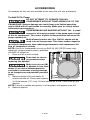
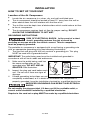
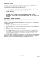
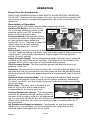
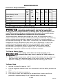
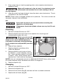
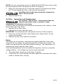
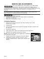
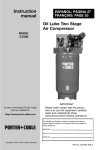
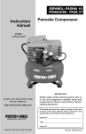
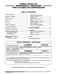
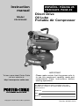
Instruction
manual
Model
CPLDC2540P
To learn more about Porter-Cable
visit our website at:
http://www.porter-cable.com
ESPAÑOL: PÁGINA 25
FRANÇAIS: PAGE 49
Direct Drive
Oil Lube
Portable Air Compressor
IMPORTANT
Please make certain that the person who is
to use this equipment carefully reads and
understands these instructions before
starting operations.
The Model and Serial No. plate is located on the frame.
Record these numbers in the spaces below and retain for
future reference.
Model No.
Type
Serial No.
Copyright © 2004 Porter-Cable Corporation
Part No. A02231-041-0
SAFETY GUIDELINES - DEFINITIONS
This manual contains information that is important for you to know and understand. This information
relates to protecting YOUR SAFETY and PREVENTING EQUIPMENT PROBLEMS. To help you
recognize this information, we use the symbols below. Please read the manual and pay attention to
these sections.
Indicates an
imminently hazardous
situation which, if not avoided, will
result in death or serious injury.
Indicates a potentially
hazardous situation
which, if not avoided, may result in
minor or moderate injury.
Indicates a potentially
hazardous situation
which, if not avoided, could result in
death or serious injury.
Used without the
safety alert symbol
indicates a potentially hazardous
situation which, if not avoided, may
result in property damage.
IMPORTANT SAFETY INSTRUCTIONS
Some dust created by power sanding, sawing, grinding, drilling, and other
construction activities contains chemicals known (to the State of California) to
cause cancer, birth defects or other reproductive harm. Some example of these chemicals are:
G
lead from lead-based paints
G
crystalline silica from bricks and cement and other masonry products
G
arsenic and chromium from chemically-treated lumber
Your risk from these exposures varies, depending on how often you do this type of work. To reduce
your exposure to these chemicals: work in a well ventilated area, and work with approved safety
equipment, always wear MSHA/NIOSH approved, properly fitting face mask or respirator when using
such tools.
When using air tools, basic safety precautions should always be followed to reduce the risk of of
personal injury.
READ AND FOLLOW ALL INSTRUCTIONS.
This tool was designed for certain applications. Porter-Cable strongly recommends that this tool NOT
be modified and/or used for any application other than for which it was designed. If you have any
questions relative to its application DO NOT use the tool until you have written Porter-Cable and we
have advised you.
Technical Service Manager
Porter-Cable Corporation
4825 Highway 45 North
P.O. Box 2468
Jackson, TN 38302-2468
A02231
2- ENG
IMPORTANT SAFETY INSTRUCTIONS
SAVE THESE INSTRUCTIONS
IMPROPER OPERATION OR MAINTENANCE OF THIS PRODUCT COULD RESULT IN
SERIOUS INJURY AND PROPERTY DAMAGE. READ AND UNDERSTAND ALL
WARNINGS AND OPERATING INSTRUCTIONS BEFORE USING THIS EQUIPMENT.
HAZARD
RISK OF EXPLOSION OR FIRE
WHAT CAN HAPPEN
HOW TO PREVENT IT
IT IS NORMAL FOR ELECTRICAL CONTACTS
WITHIN THE MOTOR AND PRESSURE SWITCH
TO SPARK.
ALWAYS OPERATE THE COMPRESSOR IN A
WELL VENTILATED AREA FREE OF
COMBUSTIBLE MATERIALS, GASOLINE OR
SOLVENT VAPORS.
IF SPRAYING FLAMMABLE MATERIALS,
LOCATE COMPRESSOR AT LEAST 20 FEET
AWAY FROM SPRAY AREA. AN ADDITIONAL
LENGTH OF HOSE MAY BE REQUIRED.
STORE FLAMMABLE MATERIALS IN A
SECURE LOCATION AWAY FROM
COMPRESSOR.
NEVER PLACE OBJECTS AGAINST OR ON
TOP OF COMPRESSOR. OPERATE
COMPRESSOR IN AN OPEN AREA AT LEAST
12 INCHES AWAY FROM ANY WALL OR
OBSTRUCTION THAT WOULD RESTRICT THE
FLOW OF FRESH AIR TO THE VENTILATION
OPENINGS.
OPERATE COMPRESSOR IN A CLEAN, DRY,
WELL VENTILATED AREA. DO NOT OPERATE
UNIT INDOORS OR IN ANY CONFINED AREA.
ALWAYS REMAIN IN ATTENDANCE WITH THE
PRODUCT WHEN IT IS OPERATING.
ALWAYS DISCONNECT ELECTRICAL POWER
BY MOVING PRESSURE SWITCH LEVER TO
THE OFF POSITION AND DRAIN TANK DAILY
OR AFTER EACH USE.
IF ELECTRICAL SPARKS FROM
COMPRESSOR COME INTO CONTACT WITH
FLAMMABLE VAPORS, THEY MAY IGNITE,
CAUSING FIRE OR EXPLOSION.
RESTRICTING ANY OF THE COMPRESSOR
VENTILATION OPENINGS WILL CAUSE
SERIOUS OVERHEATING AND COULD CAUSE
FIRE.
UNATTENDED OPERATION OF THIS
PRODUCT COULD RESULT IN PERSONAL
INJURY OR PROPERTY DAMAGE. TO
REDUCE THE RISK OF FIRE, DO NOT ALLOW
THE COMPRESSOR TO OPERATE
UNATTENDED.
3- ENG
A02231
HAZARD
RISK OF BURSTING
AIR TANK: THE FOLLOWING CONDITIONS COULD LEAD TO A WEAKENING OF THE
TANK, AND RESULT IN A VIOLENT TANK EXPLOSION AND COULD CAUSE
PROPERTY DAMAGE OR SERIOUS INJURY.
WHAT CAN HAPPEN
HOW TO PREVENT IT
1.
FAILURE TO PROPERLY DRAIN
CONDENSED WATER FROM THE
TANK, CAUSING RUST AND THINNING
OF THE STEEL TANK.
2.
MODIFICATIONS OR ATTEMPTED
REPAIRS TO THE TANK.
3.
UNAUTHORIZED MODIFICATIONS TO
THE UNLOADER VALVE, SAFETY
VALVE, OR ANY OTHER COMPONENTS
WHICH CONTROL TANK PRESSURE.
4.
EXCESSIVE VIBRATION CAN WEAKEN
THE AIR TANK AND CAUSE RUPTURE
OR EXPLOSION.
ATTACHMENTS & ACCESSORIES:
EXCEEDING THE PRESSURE RATING OF AIR
TOOLS, SPRAY GUNS, AIR OPERATED
ACCESSORIES,
TIRES
AND
OTHER
INFLATABLES CAN CAUSE THEM TO
EXPLODE OR FLY APART, AND COULD
RESULT IN SERIOUS INJURY.
DRAIN TANK DAILY OR AFTER EACH USE. IF
TANK DEVELOPS A LEAK, REPLACE IT
IMMEDIATELY WITH A NEW TANK OR REPLACE
THE ENTIRE COMPRESSOR.
NEVER DRILL INTO, WELD, OR MAKE ANY
MODIFICATIONS TO THE TANK OR ITS
ATTACHMENTS.
THE TANK IS DESIGNED TO WITHSTAND
SPECIFIC OPERATING PRESSURES. NEVER
MAKE
ADJUSTMENTS
OR
PARTS
SUBSTITUTIONS TO ALTER THE FACTORY
SET OPERATING PRESSURES.
FOR
ESSENTIAL
CONTROL
OF
AIR
PRESSURE,YOU MUST INSTALL A PRESSURE
REGULATOR AND PRESSURE GAUGE TO THE
AIR OUTLET (IF NOT EQUIPPED) OF YOUR
COMPRESSOR. FOLLOW THE EQUIPMENT
MANUFACTURERS RECOMMENDATION AND
NEVER EXCEED THE MAXIMUM ALLOWABLE
PRESSURE RATING OF ATTACHMENTS. NEVER
USE COMPRESSOR TO INFLATE SMALL LOWPRESSURE OBJECTS SUCH AS CHILDREN’S
TOYS, FOOTBALLS, BASKETBALLS, ETC.
HAZARD
RISK FROM FLYING OBJECTS
WHAT CAN HAPPEN
HOW TO PREVENT IT
THE COMPRESSED AIR STREAM CAN CAUSE
SOFT TISSUE DAMAGE TO EXPOSED SKIN
AND CAN PROPEL DIRT, CHIPS, LOOSE
PARTICLES AND SMALL OBJECTS AT HIGH
SPEED, RESULTING IN PROPERTY DAMAGE
OR PERSONAL INJURY.
ALWAYS WEAR ANSI Z87.1 APPROVED
SAFETY GLASSES WITH SIDE SHIELDS WHEN
USING THE COMPRESSOR.
NEVER POINT ANY NOZZLE OR SPRAYER
TOWARD ANY PART OF THE BODY OR AT
OTHER PEOPLE OR ANIMALS.
ALWAYS TURN THE COMPRESSOR OFF AND
BLEED PRESSURE FROM THE AIR HOSE AND
TANK BEFORE ATTEMPTING MAINTENANCE,
ATTACHING TOOLS OR ACCESSORIES.
A02231
4- ENG
HAZARD
RISK OF ELECTRICAL SHOCK
WHAT CAN HAPPEN
HOW TO PREVENT IT
YOUR AIR COMPRESSOR IS POWERED BY
ELECTRICITY.
LIKE
ANY
OTHER
ELECTRICALLY POWERED DEVICE, IF IT IS
NOT USED PROPERLY IT MAY CAUSE
ELECTRIC SHOCK.
NEVER
OPERATE
THE
COMPRESSOR
OUTDOORS WHEN IT IS RAINING OR IN WET
CONDITIONS.
REPAIRS ATTEMPTED BY UNQUALIFIED
PERSONNEL CAN RESULT IN SERIOUS
INJURY OR DEATH BY ELECTROCUTION.
ELECTRICAL GROUNDING:
FAILURE TO
PROVIDE ADEQUATE GROUNDING TO THIS
PRODUCT COULD RESULT IN SERIOUS
INJURY OR DEATH FROM ELECTROCUTION.
SEE GROUNDING INSTRUCTIONS.
NEVER OPERATE COMPRESSOR WITH
PROTECTIVE
COVERS
REMOVED
OR
DAMAGED.
ANY ELECTRICAL WIRING OR REPAIRS
REQUIRED ON THIS PRODUCT SHOULD BE
PERFORMED BY AUTHORIZED SERVICE
CENTER PERSONNEL IN ACCORDANCE WITH
NATIONAL AND LOCAL ELECTRICAL CODES.
MAKE CERTAIN THAT THE ELECTRICAL
CIRCUIT TO WHICH THE COMPRESSOR IS
CONNECTED
PROVIDES
PROPER
ELECTRICAL
GROUNDING,
CORRECT
VOLTAGE
AND
ADEQUATE
FUSE
PROTECTION.
HAZARD
RISK TO BREATHING
WHAT CAN HAPPEN
HOW TO PREVENT IT
THE COMPRESSED AIR DIRECTLY FROM
YOUR COMPRESSOR IS NOT SAFE FOR
BREATHING. THE AIR STREAM MAY
CONTAIN CARBON MONOXIDE, TOXIC
VAPORS, OR SOLID PARTICLES FROM THE
TANK. BREATHING THESE CONTAMINANTS
CAN CAUSE SERIOUS INJURY OR DEATH.
AIR OBTAINED DIRECTLY FROM THE
COMPRESSOR SHOULD NEVER BE USED TO
SUPPLY AIR FOR HUMAN CONSUMPTION. IN
ORDER TO USE AIR PRODUCED BY THIS
COMPRESSOR FOR BREATHING, SUITABLE
FILTERS AND IN-LINE SAFETY EQUIPMENT
MUST BE PROPERLY INSTALLED. IN-LINE
FILTERS AND SAFETY EQUIPMENT USED IN
CONJUNCTION WITH THE COMPRESSOR
MUST BE CAPABLE OF TREATING AIR TO ALL
APPLICABLE LOCAL AND FEDERAL CODES
PRIOR TO HUMAN CONSUMPTION.
SPRAYED MATERIALS SUCH AS PAINT, PAINT
SOLVENTS, PAINT REMOVER, INSECTICIDES,
WEED KILLERS, MAY CONTAIN HARMFUL
VAPORS AND POISONS.
WORK IN AN AREA WITH GOOD CROSSVENTILATION. READ AND FOLLOW THE
SAFETY INSTRUCTIONS PROVIDED ON THE
LABEL OR SAFETY DATA SHEETS FOR THE
MATERIAL YOU ARE SPRAYING. USE A
NIOSH/MSHA APPROVED RESPIRATOR
DESIGNED FOR USE WITH YOUR SPECIFIC
APPLICATION.
5- ENG
A02231
HAZARD
RISK OF BURNS
WHAT CAN HAPPEN
HOW TO PREVENT IT
TOUCHING EXPOSED METAL SUCH AS THE
COMPRESSOR HEAD OR OUTLET TUBES,
CAN RESULT IN SERIOUS BURNS.
NEVER TOUCH ANY EXPOSED METAL PARTS
ON COMPRESSOR DURING OR IMMEDIATELY
AFTER OPERATION. COMPRESSOR WILL
REMAIN HOT FOR SEVERAL MINUTES AFTER
OPERATION.
DO NOT REACH AROUND PROTECTIVE
SHROUDS OR ATTEMPT MAINTENANCE
UNTIL UNIT HAS BEEN ALLOWED TO COOL.
HAZARD
RISK FROM MOVING PARTS
WHAT CAN HAPPEN
HOW TO PREVENT IT
MOVING PARTS SUCH AS THE PULLEY,
FLYWHEEL AND BELT CAN CAUSE SERIOUS
INJURY IF THEY COME INTO CONTACT WITH
YOU OR YOUR CLOTHING.
NEVER OPERATE THE COMPRESSOR WITH
GUARDS OR COVERS WHICH ARE DAMAGED
OR REMOVED.
ATTEMPTING TO OPERATE COMPRESSOR
WITH DAMAGED OR MISSING PARTS OR
ATTEMPTING TO REPAIR COMPRESSOR
WITH PROTECTIVE SHROUDS REMOVED CAN
EXPOSE YOU TO MOVING PARTS AND CAN
RESULT IN SERIOUS INJURY.
ANY REPAIRS REQUIRED ON THIS PRODUCT
SHOULD BE PERFORMED BY AUTHORIZED
SERVICE CENTER PERSONNEL.
HAZARD
RISK OF FALLING
WHAT CAN HAPPEN
HOW TO PREVENT IT
A PORTABLE COMPRESSOR CAN FALL FROM
A TABLE, WORKBENCH OR ROOF CAUSING
DAMAGE TO THE COMPRESSOR AND
COULD RESULT IN SERIOUS INJURY OR
DEATH TO THE OPERATOR.
ALWAYS OPERATE COMPRESSOR IN A
STABLE SECURE POSITION TO PREVENT
ACCIDENTAL MOVEMENT OF THE UNIT. NEVER
OPERATE COMPRESSOR ON A ROOF OR
OTHER
ELEVATED
POSITION.
USE
ADDITIONAL AIR HOSE TO REACH HIGH
LOCATIONS.
HAZARD
RISK OF PROPERTY DAMAGE WHEN TRANSPORTING COMPRESSOR
(Fire, Inhalation, Damage to Vehicle Surfaces)
WHAT CAN HAPPEN
HOW TO PREVENT IT
OIL CAN LEAK OR SPILL AND COULD
RESULT IN FIRE OR BREATHING HAZARD,
SERIOUS INJURY OR DEATH CAN RESULT.
OIL LEAKS WILL DAMAGE CARPET, PAINT OR
OTHER SURFACES IN VEHICLES OR
TRAILERS.
A02231
ALWAYS PLACE COMPRESSOR ON A
PROTECTIVE MAT WHEN TRANSPORTING TO
PROTECT AGAINST DAMAGE TO VEHICLE
FROM LEAKS. REMOVE COMPRESSOR FROM
VEHICLE IMMEDIATELY UPON ARRIVAL AT
YOUR DESTINATION.
6- ENG
HAZARD
RISK OF UNSAFE OPERATION
WHAT CAN HAPPEN
HOW TO PREVENT IT
UNSAFE OPERATION OF YOUR AIR
COMPRESSOR COULD LEAD TO SERIOUS INJURY OR DEATH TO YOU OR OTHERS.
REVIEW AND UNDERSTAND ALL
INSTRUCTIONS AND WARNINGS IN THIS
MANUAL.
BECOME FAMILIAR WITH THE OPERATION
AND CONTROLS OF THE AIR COMPRESSOR.
KEEP OPERATING AREA CLEAR OF ALL
PERSONS, PETS, AND OBSTACLES.
KEEP CHILDREN AWAY FROM THE AIR
COMPRESSOR AT ALL TIMES.
DO NOT OPERATE THE PRODUCT WHEN
FATIGUED OR UNDER THE INFLUENCE OF
ALCOHOL OR DRUGS. STAY ALERT AT ALL
TIMES.
NEVER DEFEAT THE SAFETY FEATURES OF
THIS PRODUCT.
EQUIP AREA OF OPERATION WITH A FIRE
EXTINGUISHER.
DO NOT OPERATE MACHINE WITH MISSING,
BROKEN, OR UNAUTHORIZED PARTS.
7- ENG
A02231
GLOSSARY
Become familiar with these terms before operating the unit.
CFM: Cubic feet per minute.
SCFM: Standard cubic feet per minute; a unit of measure of air delivery.
PSIG: Pounds per square inch gauge; a unit of measure of pressure.
Code Certification: Products that bear one or more of the following marks:
UL, CUL, ETL, CETL, have been evaluated by OSHA certified independent
safety laboratories and meet the applicable Underwriters Laboratories
Standards for Safety.
Cut-In Pressure: While the motor is off, air tank pressure drops as you
continue to use your accessory. When the tank pressure drops to a certain low
level the motor will restart automatically. The low pressure at which the motor
automatically restarts is called “cut-in” pressure.
Cut-Out Pressure: When an air compressor is turned on and begins to run,
air pressure in the air tank begins to build. It builds to a certain high pressure
before the motor automatically shuts off - protecting your air tank from
pressure higher than its capacity. The high pressure at which the motor shuts
off is called “cut-out” pressure.
Branch Circuit: Circuit carrying electricity from electrical panel to outlet.
DUTY CYCLE
Porter-Cable air compressors should be operated on not more than a 50%
duty cycle. This means an air compressor that pumps air more than 50% of
one hour is considered misuse, because the air compressor is undersized for
the required air demand. Maximum compressor pumping time per hour is 30
minutes.
SPECIFICATIONS
Model No.
CPLDC2540P
Horsepower Peak
2.5
Bore
2.363”
Stroke
.890”
* Voltage-Single Phase
120
* * Minimum Branch Circuit Requirement
15 amps
* Fuse Type
Time Delay
Air Tank Capacity (Gallon)
4.0
Approximate Cut-in Pressure
120 PSIG
Approximate Cut-out Pressure
150 PSIG
SCFM @ 40 PSIG
5.4
SCFM @ 90 PSIG
4.0
*
This air compressor can be operated on a 15 amp circuit
if:
1. Voltage supply to circuit is normal.
2. Circuit is not used to supply any other electrical needs (lights, appliances, etc.)
3. Extension cords comply with specifications in owners manual.
4. Circuit is equipped with 15 amp circuit breaker or 15 amp time delay fuse.
If any of the above conditions cannot be met, or if operation of the air compressor
repeatedly causes interruption of the power it may be necessary to operate it from a
20 amp circuit. It is not necessary to change the cord set.
* * A circuit breaker is preferred. Use only a fuse or circuit breaker that is the same
rating as the branch circuit on which the air compressor is operated. If the air
compressor is connected to a circuit protected by fuses, use dual element time
delay fuses.
A02231
8- ENG
ACCESSORIES
Accessories for this unit are available at the store the unit was purchased.
To Add Oil To Pump
+
DO NOT ATTEMPT TO OPERATE THIS AIR
COMPRESSOR WITHOUT FIRST ADDING OIL TO THE
CRANKCASE. Serious damage can result from even limited operation
unless filled with oil and broken in correctly. Make sure to closely follow
initial start-up procedures.
COMPRESSORS ARE SHIPPED WITHOUT OIL. A small
amount of oil may be present in the pump upon receipt
of the air compressor. This is due to plant testing and does not mean the
pump contains oil.
Multi-Viscosity motor oils, like 10W 30, should not be
used in an air compressor. They leave carbon deposits
on critical components, thus reducing performance and compressor life.
Use air compressor oil only.
NOTE: Use an air compressor oil such as SAE-30 (API CG/CD heavy duty
motor oil). Under extreme winter conditions
B
use SAE-10 weight oil.
1. Place unit on a level surface.
Drain tank to release
A
air pressure before
removing the dipstick.
Make sure air vent (B)
in dipstick is free from
debris. If air vent is blocked pressure
can build in crankcase causing damage
to air compressor and possible personal
injury.
(+)Full
2. Remove dipstick (A) and slowly fill
(-)Add
crankcase with oil. Crankcase capacity
is 6 fluid ounces (177.4 ml). Oil level should be at the + (full) mark on the
dipstick.
NOTE: If the oil is added too quickly, it will overflow and appear to be full.
3. Replace dipstick.
-
9- ENG
A02231
INSTALLATION
HOW TO SET UP YOUR UNIT
Location of the Air Compressor
G
G
G
G
Locate the air compressor in a clean, dry, and well ventilated area.
The air compressor should be located at least 12" away from the wall or
other obstructions that will interfere with the flow of air.
The air filter must be kept clear of obstructions which could reduce air flow
to the air compressor.
The air compressor requires fresh air flow for proper cooling. DO NOT
ALLOW THE COMPRESSOR TO GET WET.
GROUNDING INSTRUCTIONS
RISK OF ELECTRICAL SHOCK. In the event of a short
circuit, grounding reduces the risk of shock by
providing an escape wire for the electric current. This air compressor
must be properly grounded.
The portable air compressor is equipped with a cord having a grounding wire
with an appropriate grounding plug (see following illustrations).
1. The cord set and plug with this unit contains a grounding pin. This plug
MUST be used with a grounded outlet.
IMPORTANT: The outlet being used must be installed and grounded in
accordance with all local codes and ordinances.
2. Make sure the outlet being used has
Plug
the same configuration as the
grounded plug. DO NOT USE AN
Grounded
ADAPTER. See illustration.
Outlets
3. Inspect the plug and cord before each
use. Do not use if there are signs of
damage.
Grounding Pin
4. If these grounding instructions are not
completely understood, or if in doubt as to whether the compressor is
properly grounded, have the installation checked by a qualified electrician.
IMPROPER GROUNDING CAN RESULT IN ELECTRICAL
SHOCK.
Do not modify the plug provided. If it does not fit the available outlet, a
correct outlet should be installed by a qualified electrician.
Repairs to the cord set or plug MUST be made by a qualified electrician.
A02231
10- ENG
Extension Cords
Use extra air hose instead of an extension cord to avoid voltage drop and
power loss to the motor, and to prevent overheating.
If an extension cord must be used, be sure it is:
•
a 3-wire extension cord that has a 3-blade grounding plug, and a 3-slot
receptacle that will accept the plug on the product
•
in good condition
•
no longer than 50 feet
•
12 gauge (AWG) or larger. (Wire size increases as gauge number
decreases. 10 AWG and 8 AWG may also be used. DO NOT USE 14 OR
16 AWG.)
Voltage and Circuit Protection
Refer to the Parts Manual for the voltage and minimum branch circuit
requirements.
Certain air compressors can be operated on a 15 amp circuit if the following
conditions are met.
1.
Voltage supply through branch circuit is 15 amps.
2.
Circuit is not used to supply any other electrical needs (lights, appliances,
etc.).
3.
Extension cords comply with specifications.
4.
Circuit is equipped with a 15 amp circuit breaker or 15 amp time delay
fuse. NOTE: If compressor is connected to a circuit protected by fuses,
use only time delay fuses. Time delay fuses should be marked “D” in
Canada and “T” in the US.
If any of the above conditions cannot be met, or if operation of the compressor
repeatedly causes interruption of the power, it may be necessary to operate it
from a 20 amp circuit. It is not necessary to change the cord set.
11- ENG
A02231
OPERATION
Know Your Air Compressor
READ THIS OWNER’S MANUAL AND SAFETY RULES BEFORE OPERATING
YOUR UNIT. Compare the illustrations with your unit to familiarize yourself with
the location of various controls and adjustments. Save this manual for future
reference.
Description of Operation
Become familiar with these controls before operating the unit.
On/Auto/Off Switch: Turn this switch
Tank
Outlet
Pressure
Pressure
ON to provide automatic power to the
Pressure
Switch
Gauge
Gauge
pressure switch and OFF to remove
power at the end of each use.
Pressure Switch: The pressure switch
automatically starts the motor when the
air tank pressure drops below the
factory set “cut-in” pressure. It stops the
motor when the air tank pressure
Regulator
On/Auto/Off
Switch
reaches the factory set “cut-out”
Safety Valve
pressure.
Safety Valve: If the pressure switch does not shut off the air compressor at its
“cut-out” pressure setting, the safety valve will protect against high pressure by
“popping out” at its factory set pressure (slightly higher than the pressure
switch “cut-out” setting).
Outlet Pressure Gauge: The outlet pressure gauge indicates the air pressure
available at the outlet side of the regulator. This pressure is controlled by the
regulator and is always less than or equal to the tank pressure.
Tank Pressure Gauge: The tank pressure gauge indicates the reserve air
pressure in the tank.
Regulator: Controls the air pressure shown on the outlet pressure gauge. Pull
the knob out and turn clockwise to increase pressure and counterclockwise to
decrease pressure. When the desired pressure is reached push knob in to lock
in place.
Universal Quick-Connect Body: The universal quick-connect body accepts
the three most popular styles of quick-connect plugs- Industrial, automotive
(Tru-flate), and ARO. One hand push-to-connect operation makes connections
simple and easy.
Drain Valve: The drain valve is located at the
base of the air tank and is used to drain
condensation at the end of each use.
Cooling System (not shown): This compressor
Drain
contains an advanced design cooling system. At
Valve
the heart of this cooling system is an engineered
fan. It is perfectly normal for this fan to blow air over the pump head, cylinder
sleeve, and crankcase. You know the cooling system is working when air is
being expelled.
Air Compressor Pump (not shown): Compresses air into the air tank.
Working air is not available until the compressor has raised the air tank
pressure above that required at the air outlet.
A02231
12- ENG
Dipstick: Indicates the amount of oil in the pump, the +
mark indicates full and the - mark indicates oil needs to
be added. See Oil paragraphs in the Maintenance section
for instructions.
Dipstick
Motor Thermal Overload Protector (not shown): The
motor has an automatic reset thermal overload protector.
If the motor overheats for any reason, the overload
protector will shut off the motor. The motor must be
allowed to cool down before restarting. The compressor
will automatically restart after the motor cools.
Air Intake Filter (not shown): This filter is designed to clean air coming into
the pump. This filter must always be clean and ventilation openings free from
obstructions. See "Maintenance".
Check Valve: When the air compressor is
operating, the check valve is “open”, allowing
Pressure
Release
compressed air to enter the air tank. When the
Valve
air compressor reaches “cut-out” pressure, the
check valve “closes”, allowing air pressure to
Check
Valve
remain inside the air tank.
Pressure Release Valve: The pressure release
valve located on the side of the pressure switch,
is designed to automatically release
compressed air from the compressor head and
the outlet tube when the air compressor
reaches “cut-out” pressure or is shut off. The
pressure release valve allows the motor to restart freely. When the motor stops
running, air will be heard escaping from this valve for a few seconds. No air
should be heard leaking when the motor is running, or continuous leaking after
unit reaches “cut-out” pressure.
How to Use Your Unit
How to Stop:
1.
Set the On/Auto/Off lever to “OFF”.
Before Starting
Break-in Procedure
Serious damage may result if the following
break-in instructions are not closely followed.
This procedure is required before the air compressor is put into service and
when the check valve or a complete compressor pump has been replaced.
1.
Make sure the On/Auto/Off lever is in the "OFF" position.
2.
Check oil level in pump. See “Oil” paragraph in the “Maintenance” section
for instructions.
NOTE: Pull coupler back until it clicks to prevent air from escaping through the
quick connect.
13- ENG
A02231
3.
Plug the power cord into the correct branch circuit receptacle. (Refer to
Voltage and Circuit Protection paragraph in the Installation section of this
manual.)
4.
Open the drain valve fully (counter-clockwise) to permit air to escape and
prevent air pressure build up in the air tank during the break-in period.
5.
Move the On/Auto/Off lever to "ON/AUTO" position. The compressor will
start.
6.
Run the compressor for 20 minutes. Make sure the drain valve is open and
there is minimal air pressure build-up in tank.
7.
After 20 minutes, close the drain valve (clockwise). The air receiver will fill
to “cut-out” pressure and the motor will stop.
The compressor is now ready for use.
Before Each Start-Up:
1.
Place On/Auto/Off lever to “OFF”.
2.
Pull regulator knob out, turn counter-clockwise until it stops. Push knob in
to lock in place.
3.
Attach hose and accessories. NOTE: The hose or accessory will require a
quick connect plug if the air outlet is equipped with a quick connect
socket.
Too much air pressure causes a hazardous risk
of bursting. Check the manufacturer’s
maximum pressure rating for air tools and accessories. The
regulator outlet pressure must never exceed the maximum
pressure rating.
How to Start:
1.
Turn the On/Auto/Off lever to “AUTO” and allow tank pressure to build.
Motor will stop when tank pressure reaches “cut-out” pressure.
2.
Pull the regulator knob out and turn clockwise to increase pressure. When
the desired pressure is reached push knob in to lock in place. The
compressor is ready for use.
NOTE: Always operate the air compressor in well-ventilated areas free of
gasoline or other combustible vapors. If the compressor is being used to
operate a sprayer DO NOT place near the spray area.
A02231
14- ENG
MAINTENANCE
Customer Responsibilities
Before
each
use
Daily or Every Every
after
40
8
each
hours hours
use
Every Every
160 100
Yearly
hours hours
●
Check Safety Valve
●
Drain Tank
Oil Leaks
Check Oil
Change Oil
●
●
●
●1
Air Filter
1- more frequent in dusty or humid conditions
Unit cycles automatically when power is on. When
performing maintenance, you may be exposed to
voltage sources, compressed air, or moving parts. Personal injuries can
occur. Before performing any maintenance or repair, disconnect power
source from the compressor and bleed off all air pressure.
To ensure efficient operation and longer life of the air compressor outfit, a
routine maintenance schedule should be prepared and followed. The following
routine maintenance schedule is geared to an outfit in a normal working
environment operating on a daily basis. If necessary, the schedule should be
modified to suit the conditions under which your compressor is used. The
modifications will depend upon the hours of operation and the working
environment. Compressor outfits in an extremely dirty and/or hostile
environment will require a greater frequency of all maintenance checks.
NOTE: See “Operation” section for the location of controls.
To Check Safety Valve
If the safety valve does not work properly, overpressurization may occur, causing air tank rupture or
an explosion.
1. Before starting compressor, pull the ring on the safety valve to make sure
that the safety valve operates freely. If the valve is stuck or does not
operate smoothly, it must be replaced with the same type of valve.
To Drain Tank
1.
Set the On/Auto/Off lever to “OFF”.
2.
Pull the regulator knob out and turn clockwise to set the outlet pressure to
zero.
3.
Remove the air tool or accessory.
4.
Pull ring on safety valve allowing air to bleed from the tank until tank
pressure is approximately 20 psi. Release safety valve ring.
15- ENG
A02231
5.
Drain water from air tank by opening drain valve (counter-clockwise) on
bottom of tank.
Water will condense in the air tank. If not drained, water
will corrode and weaken the air tank causing a risk of
air tank rupture.
6.
After the water has been drained, close the drain valve (clockwise). The air
compressor can now be stored.
NOTE: If drain valve is plugged, release all air pressure. The valve can then be
removed, cleaned, then reinstalled.
Oil
Drain tank to release air pressure before removing the
dipstick or oil drain plug.
Compressor head and cylinder sleeve are very hot. Do not
touch.
Checking
1.
Set the On/Auto/Off lever to “OFF”.
2.
Remove dipstick (A) and check oil on dipstick for visual signs of
contaminants (water, dirt, etc).
Make sure air vent (C)
in dipstick is free from
debris. If air vent is blocked pressure
can build in crankcase causing damage
to air compressor and possible personal
injury.
3. Wipe oil from dipstick.
Replace dipstick and allow oil to
collect on dipstick.
5.
Remove dipstick and check oil level
on dipstick, + mark indicates full and
the - mark indicates add oil. If oil level
is below - mark, slowly add oil until it
reaches the + (full) mark on the dipstick.
A
+
4.
C
-
(+)Full
(-)Add
B
NOTE: Use a air compressor oil such as SAE-30 (API CG/CD heavy duty motor
oil. Under extreme winter conditions use SAE-10 weight oil.
6.
Replace dipstick (A).
Changing
1.
Set the On/Auto/Off lever to “OFF”.
2.
Remove the dipstick (A).
3.
Remove the oil drain plug (B) and drain oil into a suitable container.
4.
Replace the oil drain plug (B).
A02231
16- ENG
NOTE: Use a air compressor oil such as SAE-30 (API CG/CD heavy duty motor
oil. Under extreme winter conditions use SAE-10 weight oil.
5.
Slowly fill crankcase with oil. Crankcase capacity is 8 fluid ounces (236.6
ml). Oil level should be at the + (full) mark on the dipstick.
Overfilling with oil will cause premature compressor
failure. Do not overfill.
6.
Replace dipstick (A).
Air Filter - Inspection and Replacement
Hot surfaces. Risk of burn. Compressor heads are
exposed when filter cover is removed. Allow
compressor to cool prior to servicing.
A dirty air filter will not allow the compressor to operate at full capacity. Keep
the air filter clean at all times.
1. Remove the air filter cover.
2. Remove the air filter from filter cover.
IMPORTANT: Do not operate the compressor with the air filter removed.
3. Place new air filter into filter cover. Refer to the “Repair Parts” for the
correct part number.
4. Replace air filter cover and lock into place.
Motor
The motor has an automatic reset thermal overload protector. If the motor
overheats for any reason, the overload protector will shut off the motor. The
motor must be allowed to cool down before restarting. The compressor will
automatically restart after the motor cools.
If the overload protector shuts the motor off frequently, check for a possible
voltage problem. Low voltage can also be suspected when:
1.
The motor does not get up to full power or speed.
2.
Fuses blow out when starting the motor; lights dim and remain dim when
motor is started and is running.
17- ENG
A02231
SERVICE AND ADJUSTMENTS
Unit cycles automatically when power is on. When doing
Maintenance, you may be exposed to voltage sources,
compressed air or moving parts. Personal injuries can occur. Before performing
any Maintenance or repair, unplug the compressor and bleed off all air
pressure.
ALL MAINTENANCE AND REPAIR OPERATIONS NOT LISTED MUST BE
PERFORMED BY TRAINED SERVICE TECHNICIAN.
●
●
●
Before servicing:
Unplug or disconnect electrical supply to the air compressor.
Bleed tank of pressure.
Allow the air compressor to cool.
To Replace Regulator
1.
Release all air pressure from air tank. See “To Drain Tank” in the
Maintenance section.
2.
Unplug outfit.
3.
Using an adjustable wrench remove the gauges and quick connect from
the regulator.
4.
Remove the regulator.
5.
Apply pipe sealant tape to the nipple on the pressure switch.
6.
Assemble the regulator and orient as shown.
NOTE: Arrow indicates flow of air. Make sure it is pointing
in the direction of air flow.
7.
Reapply pipe sealant to gauges and quick connect.
8.
Reassemble gauges and quick connect. Orient
gauges to read correctly. Tighten quick connect with
wrench.
A02231
18- ENG
Regulator
Arrow
STORAGE
Before you store the air compressor, make sure you do the following:
1.
Review the "Maintenance" section on the preceding pages and perform
scheduled maintenance as necessary.
2.
Set the On/Auto/Off lever to “OFF”.
3.
Turn the regulator counterclockwise and set the outlet pressure to zero.
4.
Remove the air tool or accessory.
5.
Pull ring on safety valve allowing air to bleed from the tank until tank
pressure is approximately 20 psi. Release safety valve ring.
6.
Drain water from air tank by opening drain valve on bottom of tank.
Water will condense in the air tank. If not drained,
water will corrode and weaken the air tank causing a
risk of air tank rupture.
7.
After the water has been drained, close the drain or drain valve.
NOTE: If drain valve is plugged, release all air pressure. The valve can then be
removed, cleaned, then reinstalled.
8.
Protect the electrical cord and air hose from damage (such as being
stepped on or run over). Wind them loosely around the compressor
handle. (If so equipped)
Store the air compressor in a clean and dry location.
19- ENG
A02231
TROUBLESHOOTING
Performing repairs may expose voltage sources, moving
parts or compressed air sources, moving parts or
compressed air sources. Personal injury may occur. Prior to attempting
any repairs, unplug the air compressor and bleed off all air tank air
PROBLEM
Excessive tank
pressure safety valve
pops off.
CAUSE
Pressure switch does not
shut off motor when
compressor reaches “cutout” pressure.
Pressure switch “cut-out”
too high.
CORRECTION
Move On/Auto/Off lever to
the “OFF” position, if the
outfit does
not shut off contact a
Trained Service Technician.
Contact a Trained Service
Technician.
Air leaks at
fittings.
Tube fittings are not tight
enough.
Tighten fittings where air can
be heard escaping. Check
fittings with soapy water
solution. DO NOT
OVERTIGHTEN.
Air leaks at or
inside check
valve
Check valve seat damaged.
A defective check valve
results in a constant air leak
at the pressure release valve
when there is pressure in the
tank and the compressor is
shut off. Contact a Trained
Service Technician to
replace check valve.
Air leaks at
pressure switch
release valve.
(if equipped)
Defective pressure switch
release valve.
Contact a Trained Service
Technician.
Air leaks in air
tank or at air
tank welds.
Defective air tank.
Air tank must be replaced.
Do not repair the leak.
Do not
drill into,
weld or otherwise modify
air tank or it will weaken.
The tank can rupture or
explode.
Air leaks
between head
and valve plate.
Leaking seal.
Contact a Trained Service
Technician.
A02231
20- ENG
CAUSE
PROBLEM
CORRECTION
Pressure reading It is normal for “some”
on the regulated pressure drop to occur.
pressure gauge
(if equipped)
drops when an
accessory is
used.
If there is an excessive amount
of pressure drop when the
accessory is used, adjust the
regulator as instructed in the
Operation section.
NOTE: Adjust the regulated
pressure under flow conditions
(while accessory is being
used).
Air leak from
safety valve.
Possible defect in safety
valve.
Operate safety valve manually
by pulling on ring. If valve still
leaks, it should be replaced.
Compressor is
not supplying
enough air to
operate
accessories.
Prolonged excessive use of
air.
Compressor is not large
enough for air requirement.
Decrease amount of air usage.
Hole in hose.
Check the accessory air
requirement. If it is higher than
the SCFM or pressure supplied
by your air compressor, you
need a larger compressor.
Check and replace if required.
Check valve restricted.
Remove and clean, or replace.
Air leaks.
Tighten fittings.
Restricted air intake filter
Clean or replace air intake
filter. Do not operate the air
compressor with the filter
removed. Refer to the “Air
Filter” paragraph in the
“Maintenance “ section.
Restricted air
intake
Dirty air filter.
Clean or replace. See Air Filter
paragraph in the Maintenance
section.
Regulator knob
has continuous
air leak.
Damaged regulator
Replace
Regulator will
not shut off air
outlet.
Damaged regulator
Replace
21- ENG
A02231
PROBLEM
Motor will not
run.
CORRECTION
CAUSE
Motor overload protection
switch has tripped
Let motor cool off and
overload switch will
automatically reset.
Tank pressure exceeds
pressure switch “cut-in”
pressure.
Motor will start automatically
when tank pressure drops
below “cut-in” pressure of
pressure switch.
Check valve stuck open.
Contact a Trained Service
Technician.
Loose electrical
connections.
Check wiring connection
inside pressure switch and
terminal box area.
Possible defective motor
or starting capacitor.
Have checked by a Trained
Service Technician.
Paint spray on internal
motor parts.
Have checked by a Trained
Service Technician. Do not
operate the compressor in the
paint spray area. See
flammable vapor warning.
Pressure release valve on
pressure switch has not
unloaded head pressure.
Bleed the line by pushing the
lever on the pressure switch to
the “off” position; if the valve
does not open, replace switch.
Fuse blown, circuit breaker
tripped.
1.
2.
3.
4.
A02231
22- ENG
Check fuse box for blown
fuse and replace as
necessary. Reset circuit
breaker. Do not use a fuse
or circuit breaker with
higher rating than that
specified for your
particular branch circuit.
Check for proper fuse. You
should use a time delay
fuse.
Check for low voltage
conditions and/or proper
extension cord.
Disconnect the other
electrical appliances from
circuit or
operate the
compressor on its own
branch circuit.
PROBLEM
CAUSE
Knocking Noise. Possible defect in safety
valve.
Squealing
sound.
CORRECTION
Operate safety valve manually
by pulling on ring. If valve still
leaks, it should be replaced.
Defective check valve.
Contact a Trained Service
Technician.
Compressor mounting
screws loose
Tighten mounting screws,see
Parts manual for torque
specifications.
Carbon build-up in pump
Have checked by a Trained
Service Technician.
Compressor pump has no
oil.
See Oil-Checking paragraph in
the Maintenance section.
23- ENG
A02231
LIMITED WARRANTY
PORTER-CABLE CORPORATION warrants to the original purchaser that all products covered under this
warranty are free from defects in material and workmanship. Products covered under this warranty include air
compressors, air tools, service parts, pressure washers, and generators, which have the following warranty
periods:
3 YEARS - Limited warranty on 2-stage oil-free air compressor pumps that operate at 1725 RPM.
2 YEARS - Limited warranty on oil-lubricated air compressor pumps.
1 YEAR - Limited warranty on all other air compressor components.
2 YEARS - Limited warranty on electric generator alternators.
1 YEAR - Limited warranty on other generator components.
2 YEARS - Limited warranty on pneumatic air tools as described in Porter-Cable general catalog.
1 YEAR - Limited warranty on pressure washers used in consumer applications (i.e. personal residential
household usage only).
90 DAY - Pressure washers used for commercial applications (income producing) and service parts.
1 YEAR - Limited warranty on all accessories.
Porter-Cable will repair or replace, at Porter-Cable's option, products or components which have failed
within the warranty period. Service will be scheduled according to the normal work flow and business
hours at the service center location, and the availability of replacement parts. All decisions of PorterCable Corporation with regard to this limited warranty shall be final.
This warranty gives you specific legal rights, and you may also have other rights which vary from state to
state.
RESPONSIBILITY OF ORIGINAL PURCHASER (initial User):
• To process a warranty claim on this product, DO NOT return it to the retailer. The product must be
evaluated by an Porter-Cable Authorized Warranty Service Center. For the location of the nearest PorterCable Authorized Warranty Service Center call 1-888-559-8550, 24 hours a day, 7 days a week.
• Retain original cash register sales receipt as proof of purchase for warranty work.
• Use reasonable care in the operation and maintenance of the product as described in the Owners
Manual(s).
• Deliver or ship the product to the nearest Porter-Cable Authorized Warranty Service Center. Freight costs,
if any, must be paid by the purchaser.
• Air compressors with 60 and 80 gallon tanks will be inspected at the site of installation. Contact the
nearest Porter-Cable Authorized Warranty Service Center that provides on-site service calls, for service
call arrangements.
• If the purchaser does not receive satisfactory results from the Porter-Cable Authorized Warranty Service
Center, the purchaser should contact Porter-Cable.
THIS WARRANTY DOES NOT COVER:
• Merchandise sold as reconditioned, used as rental equipment, and floor or display models.
• Merchandise that has become damaged or inoperative because of ordinary wear, misuse*, cold, heat, rain,
excessive humidity, freeze damage, use of improper chemicals, negligence, accident, failure to operate
the product in accordance with the instructions provided in the Owners Manual(s) supplied with the
product, improper maintenance, the use of accessories or attachments not recommended by PorterCable, or unauthorized repair or alterations.
* An air compressor that pumps air more than 50% during a one hour period is considered misuse
because the air compressor is undersized for the required air demand.
• Repair and transportation costs of merchandise determined not to be defective.
• Costs associated with assembly, required oil, adjustments or other installation and start-up costs.
• Expendable parts or accessories supplied with the product which are expected to become inoperative or
unuseable after a reasonable period of use, including but not limited to sanding disks or pads, saw and
shear blades, grinding stones, springs, chisels, nozzles, o-rings, air jets, washers and similar accessories.
• Merchandise sold by Porter-Cable which has been manufactured by and identified as the product of
another company, such as gasoline engines. The product manufacturer's warranty, if any, will apply.
• ANY INCIDENTAL, INDIRECT OR CONSEQUENTIAL LOSS, DAMAGE, OR EXPENSE THAT MAY
RESULT FROM ANY DEFECT, FAILURE OR MALFUNCTION OF THE PRODUCT IS NOT COVERED BY
THIS WARRANTY. Some states do not allow the exclusion or limitation of incidental or consequential
damages, so the above limitation or exclusion may not apply to you.
• IMPLIED WARRANTIES, INCLUDING THOSE OF MERCHANTABILITY OR FITNESS FOR A
PARTICULAR PURPOSE, ARE LIMITED TO ONE YEAR FROM THE DATE OF ORIGINAL PURCHASE.
Some states do not allow limitations on how long an implied warranty lasts, so the above limitations may
not apply to you.
Porter-Cable Corporation
Jackson, TN USA
1-888-559-8550