1
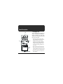
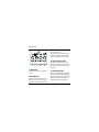
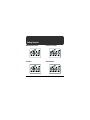
Owner’s Manual
AC
DC
AC & BATTERY
POWERED
FET
Thank you, and congratulations on your choice of BOSS MD-2 Mega Distortion.
Before using this unit, carefully read the sections entitled: “USING THE UNIT SAFELY”
and “IMPORTANT NOTES” (separate sheet). These sections provide important information concerning the proper operation of the unit. Additionally, in order to feel assured
that you have gained a good grasp of every feature provided by your new unit, this manual should be read in its entirety. The manual should be saved and kept on hand as a convenient reference.
* A battery is supplied with the unit. The life of this battery may be limited, however, since its
primary purpose was to enable testing.
Copyright © 2001 BOSS CORPORATION
All rights reserved. No part of this publication may be reproduced in any form without
the written permission of BOSS CORPORATION.
2
Features
● This new distortion unit delivers straight, powerful distortion sounds.
● Two knobs, “GAIN BOOST” and “DIST,” allow you to create a wide variety of distortion sounds, from mild to extreme.
● You can use the “BOTTOM” knob to get sound with more emphasis on the low end.
3
Panel Description
1. AC Adaptor Jack
fig.01
1 2
3
Accepts connection of an AC Adaptor (optionally available BOSS PSA-Series). By
using an AC Adaptor, you can play without being concerned about how much battery power you have left.
4
5
6
4
* Use only the specified AC adaptor (PSASeries), and make sure the line voltage at the
installation matches the input voltage
specified on the AC adaptor's body. Other
AC adaptors may use a different polarity, or
be designed for a different voltage, so their
use could result in damage, malfunction, or
electric shock.
* If there are batteries in the unit while an AC
adaptor is being used, normal operation will
continue should the line voltage be interrupted
(power blackout or power cord disconnection).
* As soon as you connect the AC adaptor, the
unit is turned on.
Panel Description
2. CHECK Indicator
4. INPUT Jack
This indicator shows whether an effect is
ON/OFF, and also doubles as the Battery
Check indicator. The indicator lights when
an effect is ON.
This jack accepts input signals (coming
from a guitar, some other musical instrument, or another effects unit).
* If this indicator goes dim or no longer lights
while an effect is ON, the battery is near
exhaustion and should be replaced immediately. For instructions on how to replace the
battery, please refer to “Changing the Battery
(p. 10).”
* The CHECK indicator is designed for
providing information about effects—such as
their on/off status. It does not indicate
whether the power is on or off.
3. OUTPUT Jack
The OUTPUT jack is used to connect the
unit to an amplifier or another device.
* The INPUT jack also serves as the power
switch. Power is turned on whenever a plug is
inserted into the INPUT jack, and is turned
off when the plug is disconnected. When not
using the unit, you should disconnect any
cord connected to the INPUT jack.
5. Pedal Switch
This switch turns the effects ON/OFF.
6. Thumbscrew
This thumbscrew is loosened to open the
pedal, allowing battery replacement.
* For instructions on how to replace the battery,
please refer to “Changing the Battery (p. 10).”
5
Panel Description
9. TONE Knob
This controls the tone.
Rotating the knob counterclockwise will
make the sound milder, while rotating it
clockwise will make the sound sharper.
10. DIST (Distortion) Knob
7
8 9
10
11
fig.02
7. LEVEL Knob
This knob adjusts the level of the effect
sounds.
8. BOTTOM Knob
Adjusts the amount of boost in the low
end. The lower frequencies are emphasized more as the knob is turned clockwise.
6
This adjusts the amount of distortion.
Rotating it clockwise increases the effect,
whereas counterclockwise rotation reduces the effect.
11. GAIN BOOST Knob
Adds even more distortion, in addition to
that obtained with the DIST knob setting.
The further clockwise you turn the knob,
the more powerful the distortion gets, creating sounds that are really expansive.
Connections
fig.03
AC adaptor
PSA-series (option)
OUT 9V DC/200mA
Electric guitar
Guitar Amplifier
7
Connections
* Inserting a plug into the INPUT Jack will automatically switch the unit on.
* To prevent malfunction and/or damage to speakers or other devices, always turn down the volume,
and turn off the power on all devices before making any connections.
* If there are batteries in the unit while an AC adaptor is being used, normal operation will continue
should the line voltage be interrupted (power blackout or power cord disconnection).
* Once the connections have been completed (p. 7), turn on power to your various devices in the
order specified. By turning on devices in the wrong order, you risk causing malfunction and/or
damage to speakers and other devices.
When powering up:
Turn on the power to your guitar amp last.
When powering down: Turn off the power to your guitar amp first.
* Always make sure to have the volume level turned down before switching on power. Even with the
volume all the way down, you may still hear some sound when the power is switched on, but this is
normal, and does not indicate a malfunction.
* When operating on battery power only, the unit’s indicator will become dim when battery power
gets too low. Replace the battery as soon as possible.
8
Operating the Unit
3. Adjust the depth of the Distortion
effect using the DIST knob and GAIN
BOOST knob.
fig.05
* Turning both knobs all the way up will result
in increased noise.
4. Adjust the tone using the TONE knob.
5. Adjust the degree of low-end boost
with the BOTTOM knob.
6
5
4
3
1. When you have made the necessary
connections, set the knobs as shown in
the illustration.
6. Adjust the LEVEL knob so that the
level of the sound obtained when the
effect is on is equal to that obtained
when it is off.
2. Depress the pedal switch to turn the
effect on. (Make sure the CHECK indicator lights.)
9
Changing the Battery
When the indicator goes dim or no longer
lights while an effect is on, it means that
the battery is nearly dead and must be replaced.
Replace the battery following the steps below.
fig.09
Thumbscrew
Pedal
Spring Base
Battery Snap
Cord
Coil Spring
Guide Bush
Hole
Battery
Snap
Battery Housing
9V Battery
10
1. Loosen the thumbscrew at the front of
the pedal, then lift the pedal upwards
to open the unit.
* The thumbscrew can be left in the pedal while
changing the battery.
2. Remove the old battery from the battery
housing, and remove the snap cord connected to it.
3. Connect the snap cord to the new battery,
and place the battery inside the battery
housing.
* Be sure to carefully observe the battery's
polarity (+ versus -).
4. Slip the coil spring onto the spring base on
the back of the pedal, then close the pedal.
* Carefully avoid getting the snap cord caught
in the coil spring.
5. Finally, insert the thumbscrew into the
guide bush hole and fasten it securely.
Troubleshooting
Power won’t come on/
CHECK indicator doesn’t light:
● Is the specified adaptor (PSA-series;
sold separately) properly connected?
Check the connection once more (p. 7).
● Is the battery low or dead?
Replace with a new battery (p. 10).
● Is the guitar connected properly to the
INPUT jack?
Check the connection once more (p. 7).
* To prevent excess battery drainage, turn the
power on without the plug inserted in the
INPUT jack.
* The battery that was supplied with the unit is
for temporary use-intended primarily for
testing its operation. For using the unit for
more extended periods of time, we
recommend the use of alkaline batteries.
* The CHECK indicator is designed for
providing information about effects—such as
their on/off status. It does not indicate
whether the power is on or off.
No sound / Low volume:
● Is the MD-2 properly connected to
your instrument?
Check the connection once more (p. 7).
● Could the LEVEL knob be turned too
far down?
The further counterclockwise you turn
the LEVEL knob, the more the volume
is reduced when the effect is on. Turn
the LEVEL knob clockwise.
● Is the volume turned down on any
guitar amp or effects device you have
connected?
11
Setting Samples
MD-2 Standard Sound
Powerful Low Boost
fig.10
fig.12
Overdrive
Solid Distortion
fig.11
fig.13
12
Specifications
MD-2: Mega Distortion
Nominal Input Level...................-20 dBu
Input Impedance..........................1 M Ω
Nominal Output Level................-20 dBu
Output Impedance ......................1 k Ω
Equivalent Input Noise Level ....-110 dBu (IHF-A, Typ.)
Controls.........................................Pedal Switch, GAIN BOOST Knob, DIST (distortion) Knob,
TONE Knob, BOTTOM Knob, LEVEL Knob
Indicator........................................CHECK Indicator (Serves also as battery check indicator)
Connectors....................................INPUT Jack, OUTPUT Jack, AC Adaptor Jack (DC 9 V)
Power Supply...............................DC 9 V; Dry battery (9 V type) S-006P/9 V (6F22/9 V)
Dry battery (9 V type) 6AM6/9 V (alkaline)
AC Adaptor (PSA-series: optional)
Current Draw ...............................18 mA (DC 9 V)
* Expected battery life under continuous use:
Carbon: 18 hours
These figures will vary depending on the actual conditions of use.
13
Specifications
Dimensions ...................................70 (W) x 125 (D) x 55 (H) mm
2-3/4 (W) x 4-15/16 (D) x 2-3/16 (H) inches
Weight ...........................................410 g/ 15 oz (including battery)
Accessories....................................Owner's Manual, Leaflet (“USING THE UNIT SAFELY,”
“IMPORTANT NOTES,” and “Information”)
Dry battery (9 V type) S-006P/9 V (6F22/9 V)
* The battery that was supplied with the unit is for temporary
use-intended primarily for testing its operation.
Options..........................................AC Adaptor: PSA-series
* 0 dBu = 0.775 Vrms
* In the interest of product improvement, the specifications and/or appearance of this unit are
subject to change without prior notice.
14
For EU Countries
This product complies with the requirements of
European Directive 89/336/EEC.
G6017456