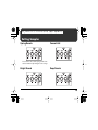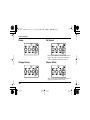
1
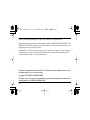
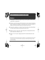
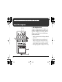
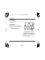
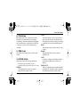
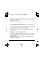
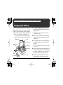
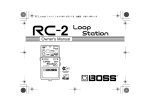
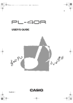
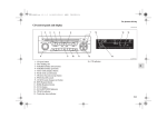
RV-5_e.book 1 ページ 2002年7月23日 火曜日 午後5時32分
Owner’s Manual
AC
DC
AC & BATTERY
POWERED
FET
RV-5_e.book 2 ページ 2002年7月23日 火曜日 午後5時32分
Thank you, and congratulations on your choice of BOSS RV-5 Digital Reverb.
Before using this unit, carefully read the sections entitled: “USING THE UNIT SAFELY” and
“IMPORTANT NOTES” (separate sheet). These sections provide important information concerning the proper operation of the unit.
Additionally, in order to feel assured that you have gained a good grasp of every feature provided by your new unit, this manual should be read in its entirety. The manual should be
saved and kept on hand as a convenient reference.
A battery is supplied with the unit. The life of this battery may be limited, however, since
its primary purpose was to enable testing.
Copyright © 2002 BOSS CORPORATION
All rights reserved. No part of this publication may be reproduced in any form without the
written permission of BOSS CORPORATION.
2
RV-5_e.book 3 ページ 2002年7月23日 火曜日 午後5時32分
Features
● This high-quality, multifunction digital reverb gives you the quality of a studio effect, but
condensed into a compact pedal.
● Models the sound of the spring reverb from Accutronics, a name synonymous with spring
reverb. The emulation on modeling is so realistic that even the sound of the oscillations resulting from the mutual interference between dual springs is reproduced.
● Comes with a completely new “modulate” feature for the reverb, which adds modulation
to the hall reverb, producing an extremely pleasant reverb sound.
● Includes a new type of “gate reverb.” This reverb produces a uniquely distinctive effect
which condenses the reverberation sound.
● Thanks to a 2-in/2-out stereo configuration, the RV-5 offers three dimensional reverb
sound.
* All product names mentioned in this document are trademarks or registered trademarks of their respective
owners. These names, as used in this manual, are for the purpose of accurately describing the sounds
created with modeling.
3
RV-5_e.book 4 ページ 2002年7月23日 火曜日 午後5時32分
Panel Description
1. AC Adaptor Jack
fig.01
1 2
3
Accepts connection of an AC Adaptor (optionally available BOSS PSA-Series). By using an AC Adaptor, you can play without
being concerned about how much battery
power you have left.
4
* As soon as you connect the AC adaptor, the unit
is turned on.
* If there are batteries in the unit while an AC
adaptor is being used, normal operation will
continue should the line voltage be interrupted
(power blackout or power cord disconnection).
* Use only the specified AC adaptor (PSA-Series).
5
6
4
RV-5_e.book 5 ページ 2002年7月23日 火曜日 午後5時32分
Panel Description
2. CHECK Indicator
This indicator shows whether an effect is
ON/OFF, and also doubles as the Battery
Check indicator. The indicator lights when
an effect is ON.
* If this indicator goes dim or no longer lights
while an effect is ON, the battery is near
exhaustion and should be replaced immediately.
For instructions on changing the battery, refer
to “Changing the Battery” (p. 12).
* The CHECK indicator shows whether the effect
is being applied or not. It does not indicate
whether the power to the device is on or not.
3. OUTPUT-A (MONO) Jack
OUTPUT-B Jack
The output jacks are used to connect the unit
to an amplifier or another effects unit.
4. INPUT-A (MONO) Jack
INPUT-B Jack
These jacks accept input signals (coming
from a guitar, some other musical instrument, or another effects unit).
* The unit’s functions differ according to how it is
connected. Refer to “Outputting Only the
Effect” (p. 11).
* When running the unit on battery power, the
INPUT-A (MONO) and INPUT-B jacks double
as power switches. Power to the unit is turned
on when you plug into the INPUT-A (MONO)
or INPUT-B jack; the power is turned off when
the cable is unplugged. Be sure to disconnect
any cord plugged into the INPUT-A (MONO)
or INPUT-B jack when not using this effects
device. When the AC adaptor is used, the power
remains on at all times, and this function is
disabled.
5
RV-5_e.book 6 ページ 2002年7月23日 火曜日 午後5時32分
Panel Description
5. Pedal Switch
Used for switching effects on/off, and for inputting the tempo.
fig.02
7
8
9
10
6. Thumbscrew
When this screw is loosened, the pedal will
open, allowing you to change the battery.
* For instructions on changing the battery, refer
to “Changing the Battery” (p. 12).
7. E.LEVEL (effect level) Knob
This adjusts the volume of the effect sound.
Turn the knob to the right (clockwise) to increase the effect sound.
6
RV-5_e.book 7 ページ 2002年7月23日 火曜日 午後5時32分
Panel Description
8. TONE Knob
This adjusts the tone of the reverb sound.
The more you turn the knob to the right
(clockwise) of center (standard), the brighter
the sound becomes; turn the knob to the left
of center to create a sound with greater
warmth.
9. TIME Knob
This adjusts the length (time) of the reverb
sound.
10. MODE Switch
Selects the reverb effect and pedal mode.
* Immediately after the MODE switch is
switched, operating the pedal produces no result.
SPRING:
This simulates the sound of a guitar
amp’s built-in spring reverb.
PLATE:
This simulates the sound of a plate echo (a
type of reverb that uses the vibrations of a
metal plate). It provides a metallic-sounding
reverberation with an extended high end.
HALL:
This simulates the reverb sound of a larger hall.
ROOM:
This simulates the reverb sound of a
smaller room.
GATE:
Produces a uniquely distinctive effect in
which the reverberation sound is condensed.
MODULATE:
This is a completely new reverb that adds
modulation to the hall reverb to produce
an extremely pleasant reverb sound.
7
RV-5_e.book 8 ページ 2002年7月23日 火曜日 午後5時32分
Connections
fig.03
AC adaptor
BOSS PSA-series (option)
Keyboard
OUT DC 9V/200mA
Electric
Guitar
Guitar Amplifier
* Be sure to lower the output level of any device being connected.
8
RV-5_e.book 9 ページ 2002年7月23日 火曜日 午後5時32分
Connections
* When running the unit on battery power, inserting a plug into the INPUT-A (MONO) or INPUT-B Jack
will automatically switch the unit on.
* The use of an AC adaptor is recommended as the unit’s power consumption is relatively high. Should you
prefer to use batteries, please use the alkaline type.
* To prevent malfunction and/or damage to speakers or other devices, always turn down the volume, and
turn off the power on all devices before making any connections.
* If there are batteries in the unit while an AC adaptor is being used, normal operation will continue should
the line voltage be interrupted (power blackout or power cord disconnection).
* Once the connections have been completed (p. 8), turn on power to your various devices in the order
specified. By turning on devices in the wrong order, you risk causing malfunction and/or damage to
speakers and other devices.
When powering up:
Turn on the power to your guitar amp last.
When powering down: Turn off the power to your guitar amp first.
* Always make sure to have the volume level turned down before switching on power. Even with the volume
all the way down, you may still hear some sound when the power is switched on, but this is normal, and
does not indicate a malfunction.
* When operating on battery power only, the unit’s indicator will become dim when battery power gets too
low. Replace the battery as soon as possible.
9
RV-5_e.book 10 ページ 2002年7月23日 火曜日 午後5時32分
Operating the Unit
1. When you have made the necessary connections (p. 8), depress the pedal switch
to turn the effect on. (the CHECK indicator turns red.)
fig.05
* The unit’s functions differ according to how it is
connected. Refer to “Outputting Only the
Effect” (p. 11).
2. Select the mode with the MODE switch.
5
4
3
2
3. Adjust the reverb time with the TIME
knob.
4. Adjust the tone of the reverb sound with
the TONE knob.
5. Adjust the effect volume level with the
E.LEVEL knob.
10
RV-5_e.book 11 ページ 2002年7月23日 火曜日 午後5時32分
Outputting Only the Effect
By plugging into INPUT-B, you can have only the effect sound be output (the direct sound is
not output).
RETURN
SEND
RETURN
SEND
* When the effect is off, the output from OUTPUT-A and OUTPUT-B is muted.
Mixer
Guitar Amplifier
* Make sure the input/output levels of devices being connected are matched appropriately.
* When using a guitar amp to send/return the direct sound as well, connect to INPUT-A (MONO).
11
RV-5_e.book 12 ページ 2002年7月23日 火曜日 午後5時32分
Changing the Battery
When the indicator goes dim or no longer
lights while an effect is on, it means that the
battery is nearly dead and must be replaced.
Replace the battery following the steps below.
* The use of an AC adaptor is recommended as the
unit’s power consumption is relatively high. Should
you prefer to use batteries, please use the alkaline type.
fig.09
Thumbscrew
Pedal
Spring Base
Battery Snap
Cord
2. Remove the old battery from the battery
housing, and remove the snap cord connected to it.
3. Connect the snap cord to the new battery,
and place the battery inside the battery
housing.
* Be sure to carefully observe the battery’s polarity
(+ versus –).
Guide Bush
Hole
4. Slip the coil spring onto the spring base on
the back of the pedal, then close the pedal.
* Carefully avoid getting the snap cord caught in
the pedal, coil spring and battery housing.
Battery Housing
12
* The thumbscrew can be left in the pedal while
changing the battery.
Coil Spring
Battery
Snap
9V Battery
1. Loosen the thumbscrew at the front of
the pedal, then lift the pedal upwards to
open the unit.
5. Finally, insert the thumbscrew into the
guide bush hole and fasten it securely.
RV-5_e.book 13 ページ 2002年7月23日 火曜日 午後5時32分
Troubleshooting
Power won’t come on / CHECK indicator doesn’t light:
● Is the specified adaptor (PSA-series;
sold separately) properly connected?
Check the connection once more (p. 8).
* Never use any AC adapter other than one
specified for use with the RV-5.
● Is the battery low or dead?
Replace with a new battery (p. 12).
* The battery that was supplied with the unit is
for temporary use, intended primarily for testing
its operation. For extended use, we suggest
replacing it with an alkaline battery.
● Is the guitar connected properly to the
INPUT-A (MONO) or INPUT-B jack?
Check the connection once more (p. 8).
* To prevent useless depletion of the battery when
the unit is running on battery power, the power
is switched on only when a cable is plugged in to
the INPUT-A (MONO) or INPUT-B jack.
* The CHECK indicator shows whether the effect
is being applied or not. It does not indicate
whether the power to the device is on or not.
13
RV-5_e.book 14 ページ 2002年7月23日 火曜日 午後5時32分
Troubleshooting
No sound / Low volume:
Sound is distorted:
● Is the RV-5 properly connected to your
instrument?
Check the connection once more (p. 8).
● Is the battery low?
As the battery is drained, the CHECK indicator dims, and the RV-5 may start to
function incorrectly. Replace with a new
battery (p. 12).
● Is the volume turned down on any guitar
amp or effects device you have connected?
Check the settings of the connected device.
● Do you have a stereo plug connected?
This device will not operate properly with
stereo plugs. Please use mono plugs.
● Are you connected only to INPUT-B?
The direct sound is not output when you
connect only to INPUT-B. The outputs are
muted when the effect is off, and no
sound is output (p. 11).
14
● Could the level of the sound being input
be excessive?
With some guitars, distortion may be produced. Be careful of your guitar’s output
level.
RV-5_e.book 15 ページ 2002年7月23日 火曜日 午後5時32分
Setting Samples
Spring Reverb
Concert Hall
You can derive more of the spring reverb’s characteristic ambience by muting the lower strings.
Bright Reverb
Deep Reverb
15
RV-5_e.book 16 ページ 2002年7月23日 火曜日 午後5時32分
Setting Samples
Room
Fat Sound
Effective when TIME is matched with the phrase’s
tempo. This yields an even fatter sound when
used in combination with distortion effects.
Garage Sound
Chorus Effect
Adds a sense of greater breadth and depth to arpeggios played with a clean sound.
16
RV-5_e.book 17 ページ 2002年7月23日 火曜日 午後5時32分
Specifications
RV-5: Digital Reverb
Nominal Input Level ...................... -20 dBu
Input Impedance ............................. 1 MΩ
Nominal Output Level ................... -20 dBu
Output Impedance.......................... 1 kΩ
Recommended Load Impedance ..... 10 kΩ or greater
Residual Noise................................. -93 dBu (IHF-A, Typ.): All knobs at center position
Controls ............................................ Pedal Switch, E.LEVEL knob, TONE knob, TIME knob,
MODE switch
Indicator ........................................... CHECK Indicator (Serves also battery check indicator)
Connectors ....................................... INPUT-A (MONO) jack, INPUT-B jack,
OUTPUT-A (MONO) jack, OUTPUT-B jack,
AC adaptor jack (DC 9 V)
Power Supply .................................. DC 9 V: Dry battery (9 V type) S-006P/9 V (6F22/9 V)
Dry battery (9 V type) 6AM6/9 V (alkaline)
AC Adaptor
17
RV-5_e.book 18 ページ 2002年7月23日 火曜日 午後5時32分
Specifications
Current Draw .................................. 50 mA (DC 9 V)
* Expected battery life under continuous use:
Carbon: 2 hours, Alkaline: 6 hours
These figures will vary depending on the actual conditions of use.
Dimensions ...................................... 73 (W) x 129 (D) x 59 (H) mm
2-7/8 (W) x 5-1/8 (D) x 2-3/8 (H) inches
Weight. ............................................. 440 g / 1 lb (including Battery)
Accessories ....................................... Owner’s Manual
Leaflet (“USING THE UNIT SAFELY,” “IMPORTANT NOTES,”
and “Information”)
Dry battery (9 V type) S-006P/9 V (6F22/9 V)
* The battery that was supplied with the unit is for temporary useintended primarily for testing its operation.
We also suggest replacing this with an alkaline dry cell.
Options ............................................. AC Adaptor PSA-Series
* 0 dBu = 0.775 Vrms
* In the interest of product improvement, the specifications and/or appearance of this unit are subject to
change without prior notice.
18
RV-5_e.book 19 ページ 2002年7月23日 火曜日 午後5時32分
For EU Countries
This product complies with the requirements of European Directive 89/336/EEC.
For the USA
FEDERAL COMMUNICATIONS COMMISSION
RADIO FREQUENCY INTERFERENCE STATEMENT
This equipment has been tested and found to comply with the limits for a Class B digital device, pursuant to Part 15 of the
FCC Rules. These limits are designed to provide reasonable protection against harmful interference in a residential
installation. This equipment generates, uses, and can radiate radio frequency energy and, if not installed and used in
accordance with the instructions, may cause harmful interference to radio communications. However, there is no guarantee
that interference will not occur in a particular installation. If this equipment does cause harmful interference to radio or
television reception, which can be determined by turning the equipment off and on, the user is encouraged to try to correct the
interference by one or more of the following measures:
– Reorient or relocate the receiving antenna.
– Increase the separation between the equipment and receiver.
– Connect the equipment into an outlet on a circuit different from that to which the receiver is connected.
– Consult the dealer or an experienced radio/TV technician for help.
This device complies with Part 15 of the FCC Rules. Operation is subject to the following two conditions:
(1) This device may not cause harmful interference, and
(2) This device must accept any interference received, including interference that may cause undesired operation.
Unauthorized changes or modification to this system can void the users authority to operate this equipment.
This equipment requires shielded interface cables in order to meet FCC class B Limit.
For Canada
NOTICE
This Class B digital apparatus meets all requirements of the Canadian Interference-Causing Equipment Regulations.
AVIS
Cet appareil numérique de la classe B respecte toutes les exigences du Règlement sur le matériel brouilleur du Canada.
RV-5_e.book 20 ページ 2002年7月23日 火曜日 午後5時32分
G6017360