1
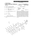
AUTOMATIC WASHER
STUDY COURSE
(BELT DRIVE MODELS)
UNDERSTANDING AUTOMATIC WASHER:
• MECHANICAL COMPONENTS
Module 3
LIT 787771 Rev. B
WHIRLPOOL CORPORATION does not assume any responsibility
or any liability in connection with the use of this manual.
© 1989, 1993, 1998 WHIRLPOOL CORPORATION
All rights reserved. No portion of this book may be reproduced in any form without
written permission from WHIRLPOOL CORPORATION.
® The trademarks WHIRLPOOL ,
trademarks of Whirlpool Corporation.
,
, and FSP are registered
INTRODUCTION
The material presented in this module is intended to provide you with an understanding of the
fundamentals of automatic washer servicing.
Major appliances have become more sophisticated, taking them out of the screwdriver and pliers
category. Their electrical circuits include several different types of automatic controls, switches,
heaters, valves, etc.. Semiconductors, solid-state controls, and other components usually
associated with radio and television electronic circuits are being engineered into automatic
washers, dryers, dishwashers, and refrigerators.
The appliance technician is emerging into a professional status of his own. He must prepare
himself now to be able to perform his duties today as well as to retain his professionalism in the
future.
No longer is on-the-job training sufficient to prepare technicians for the complicated procedures
required for todays sophisticated appliances. This training can best be obtained through organized
classroom study and application. However, much of the knowledge necessary to service todays
appliances can be obtained through study courses. Completion of this and other courses will
provide you with sufficient understanding of appliances and their operation to enable you to do
minor service. It will also serve as a valuable stepping stone to more advanced study and on-thejob training to improve your servicing skills.
Information contained in this module is used on WHIRLPOOL® appliances.
1
TABLE of CONTENTS
PAGE
CHAPTER 1 ......................................................................................... 3
MECHANICAL COMPONENTS
*TEST ........................................................ See Test Book LIT787774
*NOTE:
2
We recommend taking the TEST for MODULE 3, right
after studying it.
CHAPTER 1
MECHANICAL COMPONENTS
The mechanical components of an automatic washer
include the cabinet, suspension, spin-basket drive,
and braking mechanism, as well as the gearcase.
These are the components that most often determine
the useful life of the washer.
GEARCASE ASSEMBLY
SUPERSTRUCTURE
(MAIN DRIVE PULLEY)
MAIN DRIVE
PULLEY
CONTROL MAGNET
(WIG WAG)
GEARCASE and SUPERSTRUCTURE
For the purpose of describing the construction and
functions of these mechanical assemblies, they will
be divide into two major operating units — the
gearcase assembly (which controls agitation for the
wash and rinse functions) and the spin basket drive
and brake assembly, or superstructure, (for spin and
braking).
SUPERSTRUCTURE
(MAIN DRIVE PULLEY)
MAIN DRIVE
PULLEY
CONTROL MAGNET
(WIG WAG)
DRIVE
BELT
GEARCASE
SPIN
CAM BAR
AGITATE
CAM BAR
GEARCASE
The main function of the gearcase assembly is to
provide a means for driving the agitator; first in one
direction, then in the other, providing the necessary
washing action. The size of the arc in which the
agitator travels in each direction, and the number of
strokes it makes per minute, is determined by the
particular design of the gears that are in the gearcase
assembly, the size of the pulleys, and the motor speed
which drives these gears. Many automatic washers
are equipped with a normal-stroke gear case which
drives the agitator in a 195 arc, approximately 68
strokes per minute at high motor speed.
DRIVE MOTOR
PULLEY
Both of these units have separate pulleys driven by
a common motor and a flexible V-belt to provide a
deep, nonslip drive. The function of these two units
is controlled by the control magnet assembly (wig
wag) and two cam bars mounted on top of the
gearcase. Each unit operates independently; they
never operate at the same time on a properly adjusted
machine.
The gears in the gearcase are driven by the large
pulley secured to the top of the main drive pinion by
means of a self-locking set screw. This pulley is known
as the main drive pulley.
3
AGITATOR
SHAFT
GEAR
FORK
AGITATOR
GEAR
SECTOR
GEAR
The illustration above shows the gearcase assembly
after the pulley has been removed and the cover
raised prior to complete disassembly.
Since the sector gear meshes with the agitator gear,
this gear will turn first in one direction and then in
the other.
The main drive pinion meshes with the main drive
gear, which is mounted on a one-inch diameter stud.
CONNECTING
ROD
MAIN DRIVE
GEAR
SECTOR
GEAR
The main drive gear is coupled to the sector gear (the
section of a total gear), by means of a heavy steel
connecting rod. Therefore, as the main drive gear
rotates the sector gear oscillates.
4
To begin agitation, the agitator gear fork will move
downward, causing two of the slots in the bottom of
the agitator gear to engage the drive pin in the
agitator shaft. Thus, the agitator shaft will oscillate
as the sector gear moves the agitator gear, providing
the washing action (or agitation).
Both the agitator shaft and the gear-fork shaft are
equipped with compression springs which constantly
exert a downward pressure. The agitator gear fork is
raised by means of the agitate cam bar. This action
disengages the agitator gear from the drive pin in
the shaft, stopping the action.
The agitate cam bar is mounted on top of the gearcase
and is controlled by the plunger which moves up and
down in the agitator solenoid.
BASKET DRIVE and BRAKE
ASSEMBLY (Superstructure)
BASKET
DRIVE TUBE
BRAKE YOKE
DRIVE
PULLEY
UPPER
BRAKE
LOWER
BRAKE
CONTROL
MAGNET
AGITATE
SOLENOID
Mounted directly above the pulley on the drive tube
is the basket drive disc. A clutch lining which makes
contact with the basket drive pulley during SPIN is
mounted on the drive disc.
SPIN
CAM BAR
SPIN
SOLENOID
AGITATE
CAM BAR
DRIVE
PULLEY
NUT
Parts making up the superstructure on top of the
gearcase are associated with the basket drive (spin)
and braking. The same belt and motor pulley that
supplies the power to the agitator drive pulley also
drives the basket drive pulley.
CONTROL
MAGNET
SPRING
CLUTCH
SHAFT
UPPER
SLOT
SPIN
PLUNGER
AGITATE
CAM BAR
PIN
SPIN
CAM BAR
The basket drive pulley is a part of the basket drive
and brake assembly. It slips over the agitator shaft
and rests on the basket support collar on top of the
gearcase assembly. The basket drive pulley is always
turning clockwise whenever the main drive motor is
running. This pulley turns freely on the basket drive
tube.
GEARCASE
Like the agitator solenoid and cam bar, when the spin
solenoid is energized its plunger is pulled upward by
magnetic attraction. The bottom end of this plunger
straddles the spin cam bar, as shown above. A pin
through this plunger rides in the slot in the cam bar.
The pin in the plunger will move to the upper
portion of the slot in the cam bar when the solenoid
is energized. Since the control magnet assembly is
moving back and forth with the sector gear, this pin
pulls the cam bar away from the basket clutch shaft.
5
Because the opposite end of the cam bar is tapered
and inserted in a slot in the basket clutch shaft, it
causes the brake yoke to move downward. This causes
the basket clutch to come into contact with the
revolving basket drive pulley. Pressure is provided
by the clutch and brake pressure springs.
UPPER
BRAKE DRUM
LOWER
BRAKE DRUM
UPPER BRAKE
LINING
SPLINES
SPIN
CAM BAR
SPRING
BRAKE YOKE
The upper and lower brake drum assemblies turn
with the basket drive disc since they are splined to
its hub. When the spin solenoid is energized, the
brake linings do not contact the braking surfaces,
since the brake yoke is not applying pressure to the
brake. The brake lining may be riveted to the drum
or it may be free floating.
The upper brake drum is secured to the basket drive
tube by a self-locking screw. This tube always turns
when the basket drive disc is engaged with the
basket drive pulley.
At the end of each SPIN period, the timer switch
contacts break the circuit to the spin solenoid. When
this action occurs, the plunger in the solenoid drops,
since there is no longer any magnetic force pulling it
upward. The pin in this plunger then rides in the
lower portion of the slot in the spin cam bar and
pushes the cam bar forward. The tapered end of the
cam bar lifts the basket clutch shaft. This forces the
brake yoke upward, separating the basket clutch from
the basket pulley.
6
BASEPLATE
At the same time, the upward force of the brake yoke
brings it in contact with the lower brake lining. The
entire superstructure will be moved upward by this
action causing the upper brake lining to contact the
base plate assembly.
These two simultaneous braking actions bring the
basket to a fast, smooth stop. Four compression
springs between the two brake drums provide the
necessary force for both upper and lower braking
action.
GEARCASE and SUPERSTRUCTURE
REMOVAL
wWARNING
4. Lay the washer on its front, on a padded surface,
and remove the drive belt from the motor pulley
and the pump from the gearcase.
5. Disconnect all the electrical wires (or connectors)
from the control magnet solenoids.
6. Remove the three screws which hold the gearcase
to the baseplate.
BRACE
BOLT
Electrical Shock Hazard
Disconnect power before servicing.
Replace all panels before operating.
Failure to do so can result in death
or electrical shock.
NUT
NUTS
NUTS
When removing the gearcase and superstructure, the
following procedures should be used.
1. Unplug washer or disconnect power.
2. Remove the agitator cap and the agitator, along
with the tub ring.
NOTE: On older machines that used an agitator
drive lug, it is necessary to remove the lug before
disassembly can be continued. The drive lug can
be removed by using a drive lug puller. You can
pour hot water over the lug which will expand it
and ease its removal.
BRACE
BRACE
7. Remove the gearcase support braces attached to
both the gearcase and baseplate.
NOTE: It is very important that these braces be
reinstalled during reassembly for proper machine
function . Noise and damage to the machine can
otherwise result.
The complete gearcase and superstructure assembly
can now be pulled from the bottom of the machine.
PLASTIC
RETAINER
BRAKE
YOKE
BRAKE
YOKE
YOKE
SUPPORT
SPRING
3. Remove the spanner nut and the wash basket.
4. Insert a screwdriver to expand the slot in the
tapered basket drive block. This will release the
drive block from the spin tube.
NOTE: Sometimes it’seasier to remove the wash
basket and drive block together.
There is a plastic retainer which snaps into the brake
yoke. The yoke support then snaps into this plastic
retainer.
7
“T” BEARING
BALL
Take the brake shoe yoke spring off or unsnap the
plastic retainer. Now the complete basket drive and
brake assembly will slip off of the agitator shaft.
Next, take out the cap screw holding the cam bar
brake spring and lift it off. Then remove the screw
that holds the control magnet to the sector gear shaft.
Lift the control magnet and cam bars off.
Most machines used a steel ball mounted in a hole in
the agitator shaft. The “T” bearing has a groove in it
so that when you slide it down the agitator shaft, the
groove fits over the steel ball. Be careful, as this steel
ball may fall out of the hole in the agitator shaft.
NOTE: Some real old machines may have used a
setscrew and metal support collar bearing or a fiberite
combination support collar and thrust bearing.
The gearcase will now be free and easy to work with.
PLUNGER
SPECIAL
TOOL
AGITATE
CAM BAR
FORK
“T” BEARING
Using a special tool, slide the cam bars through the
agitator control shaft and the basket clutch shaft.
The special tool gives you leverage to overcome the
spring pressure on the agitator fork shaft. Loosen
the set screw from the main drive pulley and take it
off.
8
After removing the cap screws holding the cover to
the gearcase, lift the cover off. Careful prying with a
screwdriver may be necessary to release the cover
from the dowel pins positioning it to the case.
NOTE: Use extreme care so as not to damage the
mating surfaces.
REBUILDING the GEARCASE
When completely rebuilding a gearcase the following procedures are recommended. First, disassemble
the gearcase and clean all parts in a solvent. Use a
wire brush to help. It is important that the case be
as clean as possible; any dirt or grit can quickly ruin
a bearing or shaft. You can blow out the pinion,
sector, agitator, and fork shaft holes to remove any
hidden dirt or metal particles.
NOTE: Be sure to wear safety glasses while doing
these procedures.
Visually examine the following parts for excessive
wear:
AGITATOR
SHAFT
GEAR
FORK
CONNECTING
ROD
PINION
GEAR
Agitator Gear — If the gear is badly rounded where
it slides on the drive pin, replace it. A small amount
of wear will not affect gear operation.
Agitator Shaft — The plating on the shaft should not
be scored or damaged in the seal or bearing area.
The drive pin on the end of the shaft should not have
excessive wear.
Gear Case Cover — Check the cam bar slots for any
broken sides. If the pinion bearing is worn, only the
bearing need be replaced. If the cam bar has worn
the cover in the area of the gear fork, then a special
hardened steel washer should be used. The washer
fits over the gear fork shaft between the cam bar and
cover.
Micellaneous Items — Carefully check such things
as the agitator shaft, thrust washer, and bearing for
distortion. Inspect cam bars, pins, and plungers for
wear.
AGITATOR
GEAR
SECTOR
GEAR
Sector Gear — The teeth should have uniform wear
and be free of any pitting and sharp nicks. Check the
connecting rod hole for wear. A slight amount of play
is acceptable but the hole should not be egg shaped.
Make sure the shaft is tight in the gear.
MAIN DRIVE
GEAR
Pinion Gear — Insert the shaft of the pinion gear in
the cover bearing; there should be no play. A slight
scoring of the shaft at the bearing is acceptable as
long as the area is not undersized. Teeth areas of the
gear should appear to have uniform wear and be free
of sharp nicks.
Reassemble the gearcase using only new parts where
required. Refill the gearcase with 12 to 15 ounces of
S.A.E. No. 60, nondetergent motor oil (check specifications) before installing the cover. Prior to securing
the cover bolts, make sure that the pinion has at least
1/8 inch of vertical travel. This will insure adequate
clearance between the pinion bearing and pinion
washer after the cover bolts are tightened.
Main Drive Gear — The teeth should appear to have
uniform wear and should be free of pitting, broken
areas, and sharp nicks.
Connecting Rod — Be sure the studs are securely
staked (fastened) to the bar. The stud should show
no appreciable wear.
9
GEARCASE ADJUSTMENT
REPLACING CENTERPOST
BEARINGS and SEALS
When installing the gearcase and superstructure,
always check the tub centerpost bearings. Worn
centerpost bearings and seals should be replaced.
BEARING
PULLER
1 INCH DRIVE STUD
There are two general types of gearcases that have
been used. They can be recognized by the size of the
drive gear studs and the presence or absence of an
eccentric adjustment screw. Those gearcases with a
1 inch drive gear stud require no gear adjustment.
BEARING
INSERTER
Removal of and replacements of the upper and lower
bearings and seals is accomplished by using these
special tools.
LOWER
BEARING
ECCENTRIC
ADJUSTMENT
LOCKNUT
BASEPLATE
To check the eccentric adjustment in the home, fill
the washer with water and let it agitate. If, with the
machine agitating under a full load of water, there is
a knocking sound in the gearcase, the adjustment is
too loose. If this occurs, readjust the eccentric stud
until the knocking stops. Ease off the adjustment, as
much as possible without permitting a knock. Then
tighten the locking nut.
NOTE: The gearcase should not be carried or handled
by the agitator shaft. The spring that is between the
agitator gear and cover will allow upward travel of
the shaft. If the shaft is pulled up too far, the thrust
bearing washer may cock out of position and prevent
the shaft from proper seating on the bearing.
10
Using the puller tool the bearings and seals can be
removed.
NOTE: Before installing new centerpost beh ings and
seals, it is important that the inner wall of the entire
tube centerpost be cleaned with a wire brush. As there
is no seal directly above the lower bearing, any
foreign matter left in the centerpost could fall into
the bearing area.
CHECKING CENTERPOST and
GEARCASE ALIGNMENT
UPPER
BEARING
With the machine completely reassembled (except for
the agitator), you need to check the alignment of the
gearcase with the centerpost bearings by using the
following procedures.
MAIN DRIVE
PULLEY
SEAL
LOWER
BEARING
SPIN
CAM BAR
PLUNGER
Using the special bearing inserter tool, install a single
lip seal (with the seal lip up) in the top of the
centerpost. Then press a new bearing only into the
top and bottom of the centerpost.
The spin cam bar will need to be advanced to the
spin position. Push up on the spin control solenoid
plunger and rotate the main drive pulley until the
cam bar advances to the spin position.
Install a new single lip seal into the bottom of the
centerpost beneath the bearing, being sure that the
lip of the seal is up. Add approximately 1/2 ounce of
Rykon No. 2 grease in the lower bearing section
before installing the gearcase and superstructure.
Then, lift the basket and release it. When released,
the basket should return to its original position if
the gearcase alignment is correct.
When installing the gearcase and superstructure, be
careful not to damage the new centerpost seals when
inserting the top of the basket drive tube through
them.
Misalignment can be corrected by loosening the belt
tension, the three gearcase mounting screws and the
three support braces. This allows the agitator shaft
and spin tube to properly align themselves in the
centerpost bearings. Retighten the three gearcase
mounting screws and braces. Then readjust the belt
tension.
Before installing the agitator shaft seal and top
centerpost seal, add turbine oil in each cavity to a
level just above the bearing. Each cavity has a seal
installed just below to retain the oil.
NOTE: Install the agitator shaft seal and the top
centerpost seals with the lip up.
SPACER
If the basket does not readily move up and down,
you can correct the problem by loosening one gearcase
11
mounting screw at a time until the misalignment is
relieved. If the misalignment occurs at the gearcase
mounting screw where the support spacer is inserted,
replace the spacer. However, if it takes place at one
of the other two gearcase supports, then shim them
as needed with the special horseshoe shim washers
which are available for this purpose.
BRACE
BOLT
NUT
NUTS
NUTS
Complete the reinstallation of the gearcase and
superstructure by heating the drive lug, if used, in
hot water so that the lug can be positioned with 2 or
3 light taps of a hammer.
NOTE: The drive lug must fit the shaft tightly to
prevent noisy operation.
DRIVE BELT REPLACEMENT
Remove the rear access panel and loosen the nut
holding the motor mounting bracket in the slotted
baseplate hole. Rotate the motor to the right to
relieve the belt tension, and remove the belt from
the motor pulley. Then move the motor to the left as
far as the baseplate slot will permit.
The spin cam bar must be advanced to the spin
position. Push up on the spin control solenoid
plungner and rotate the main drive pulley until the
cam bar advances to the spin position.
BRACE
BRACE
Remove the three gearcase support braces from the
gearcase. It will be necessary to loosen the nuts at
the baseplate ends of the braces. These braces must
be replaced after the belt replacement is completed.
Remove the two pump mounting bolts and swing the
pump clear of the gearcase. When replacing the
pump, make certain that the pump lever is engaged
in the notch in the agitator cam bar before securing
the pump to the gearcase. Use only the pump bolts
with the special retaining washer to mount the pump.
Take out the gearcase mounting screw which has the
spacer. Remove the spacer.
BRAKE
SPRING
YOKE
SPIN
CAM BAR
AGITATOR
SHAFT
YOKE
SPRING
PLUNGER
CLUTCH
SPRING
SPECIAL
PULLER
SPACER
PLASTIC
RETAINER
GEARCASE
BOLT
YOKE
SUPPORT
Remove the brake yoke spring. Grasp the bottom loop
of the spring with a pair of pliers and disengage the
spring from the hole in the upper gearcase cover.
12
Use a puller to raise the clutch shaft sufficiently to
clear the cam bar, (Channel-lock pliers can also be
used in place of the puller), and then slide the cam
bar out of the clutch shaft. Then remove the puller,
allowing the shaft to fall. Insert the new belt through
the gap between the shaft and the yoke and reinsert
the cam bar.
Replace the spacer and position the new belt over
the pulleys. Replace the pump and the three support
braces. A socket wrench is an excellent timesaving
tool.
the clutch surface when the clutch is disengaged. On
those automatics that use three clutch pads on the
basket drive discs, it is necessary to line up one of
the three pads with the clutch shaft before making
the adjustment.
Use the following procedures to make any drive belt
adjustments.
AGITATORS
With the belt positioned properly over the pulleys,
adjust the belt tension by inserting a hammer handle
or some other lever between the motor mounting
brackets. Rotate the motor to the left as far as it will
go. Tighten the nut holding the motor mounting
bracket. Check the tension of the belt; it should
deflect about 1/2 inch, midway between the two
pulleys.
Agitators used on automatic washers are molded from
either bakelite or polypropylene. Although the shapes
of the agitators may vary among models, there are
only two different means of driving the agitators.
Many agitators are driven by a hexagon tapered drive
lug which is pressed onto the agitator shaft. A hex
head stud screws into the top of the agitator shaft.
The agitator cap screws onto the top of the stud and
holds the agitator down.
BASKET DRIVE CLUTCH
ADJUSTMENT
To adjust the clutch after service, start the machine
in agitation so that the clutch is disengaged and then
stop it.
CLUTCH
ADJUSTMENT
NUT
CLUTCH
PAD
NOTE: Always make sure that the rubber washer is
between the agitator and cap.
Another method of driving agitators is by utilizing
an agitator which is pressed directly onto the splined
agitator shaft, eliminating the drive lug. This type
agitator can be used on automatics with drive lugs
by removing the lug.
1/16" CLEARANCE
Adjust the nut on the basket clutch shaft to obtain a
clearance of 1/16 inch between the clutch lining and
13
SPIN BASKET
SNUBBER
The porcelain-finished basket is perforated to allow
free-flow draining. A conical-shaped bottom with a
high centerpost provides a clean smooth surface that
does not trap sediment and soil deposits.
If the basket is loose on the spin tub, it will cause
excessive noise. Correct by tightening the spanner
nut. Make sure the spin tube ears are positioned in
the drive block notches. Any wear in the drive block
notches requires replacement.
Examine the inside of the basket to be certain that
there are no sharp edges or perforations that might
cause clothing damage. If rough spots are found, sand
or buff them off. Seal the sanded areas with epoxy.
BASEPLATE
SUSPENSION
RODS
SNUBBER
PLATE
SNUBBER
SNUBBER
SPRING
A snubber is used on each machine to reduce the
motion of the baseplate and tub assembly during spin
acceleration. This should prevent an unbalanced load
from causing the baseplate to strike the cabinet.
The snubber assembly consists of a tempered-steel
wire spring secured to the right rear corner gusset of
the cabinet, and a snubber pad that presses against
the top of the tub ring.
If there is excessive vibration or noise due to a worn,
loose, or oily snubber, the snubber pad must be
replaced. To replace it, unlatch and raise the top
assembly and then lift up the snubber spring and
remove the snubber pad.
TUB
There are two types of tubs used — porcelain or
Duratite (a plastic). They cause almost no service
problems.
The baseplate provides the mounting for the tub,
gearcase assembly, and main motor. The baseplate
is suspended from the top of the cabinet assembly by
three suspension rods. These rods are mounted
in a manner that permits limited movement of
the mechanism without transmitting vibration to the
cabinet.
Each suspension rod is fitted with a rubber ball at
its upper and lower ends. These suspension balls are
under tension when enclosed between the socket and
cap. The flexing of the ball permits a limited amount
of movement to the baseplate assembly.
14
CENTERPOST BEARINGS and SEALS
HINGED TOP
Because of oversudsing, lack of lubricant, or normal
wear, it is sometimes necessary to replace the
centerpost bearings and seals. To check for such wear,
raise the top, and grasp the agitator cap with one
hand and the spin basket with the other hand. Hold
the basket firmly, and vigorously shake the agitator
back and forth. A worn bearing will click slightly or
feel loose. This condition can cause a noise complaint
and/or torn clothing.
TUB RING
On machines where the top of the flange is straight,
the brown or green and black clips must be used.
TUB
FLANGE
BLACK
CLIP
(SHORT)
The cabinet top is hinged at the rear to provide
access for servicing many of the components of the
automatic washer. To raise the hinged top assembly,
raise the lid, grasp the top assembly at the front of
the lid opening, pull slightly forward and raise the
top upward. It will pivot back on its hinges.
BROWN OR
GREEN CLIP
(LONG)
OR
FRONT OF
WASHER
On machines where the top of the tub flange curls out,
the red clips must be used.
CLIP
TUB
FLANGE
RED
CLIP
FRONT OF
WASHER
The tub ring, or splash shield, is seated on top of the
tub. The tub ring is held in place by four clips. The
clip located at the trough area is shorter than the
other three.
A rubber gasket is used to provide a cushion between
the tub ring and the tub. The gasket provides a tight
seal around the top rim to prevent water from going
out over the top of the tub during the spin cycle. It
also helps to prevent water from splashing over the
top during agitation.
Using a putty knife, place the blade between the top
and front cabinet panel in one corner, about 2-1/2
inches in from the edge. Push in on the putty knife to
release the clip while lifting up on the corner of the
top. Do the same to the other front corner.
NOTE: Do not pry or you may ruin the finish.
15
CHANGES to LATER MODEL LARGE
CAPACITY WASHERS
Changes were phased into production on all large
capacity models. The modifications that were made
involved the basket, baseplate, superstructure, and
gearcase.
The basket is the same size that was used on earlier
large capacity models, except that it has a shorter
centerpost. The baseplate centerpost is also shorter.
A standard 14-pound gearcase and superstructure
assembly is used in the modified large capacity unit.
AGITATOR
SHAFT
SEAL
SEAL
TURBINE OIL
SPACER
DRIVE
TUBE
BEARING
CENTER
POST
FILL CAVITY WITH
RYKON #2 GREASE
SEALS
SEALS
BEARING
FILL CAVITY WITH
EXTRA HEAVY
TURBINE OIL
SPACER
14"
SEAL
FILL CAVITY WITH
RYKON #2 GREASE
BEARING
SEAL
Since the basic tub and basket size remained the
same, the high water level in the large capacity unit
is still about fourteen inches in the basket. Using
the standard gearcase, superstructure, and shorter
centerpost now places the water level above the
centerpost and agitator seals.
16
To prevent water from entering the centerpost or
agitator shaft areas, three seals were added and the
location of two (2) bearings was changed. The upper
centerpost bearing is pressed in about 5/8 inch deeper.
This allows room for two upper centerpost seals.
Revised bearing tools and seal installers are required
for the modified unit. Because of the upper bearing
position and the additional seal, a deeper bearing
puller cap and a longer screw are needed to pull the
bearing. The shoulder on the upper mandrel has been
lengthened to properly seat the upper bearing.
HIGH WATER
LEVEL
Procedures for using the revised tools are unchanged.
The new bearing tools are available from Robinair
through your local parts distributor.
BASKET
POST
SHIELD
AIR POCKET
DRIVE
BLOCK
WATER
The position of the agitator bearing in the spin tube
was also lowered 5/8 of an inch and a second seal
was added to this area. A third new seal is the spin
tube shield. The shield is slipped over the spin tube
and rests about 1/2 inch above the centerpost. The
shield forms an air pocket in the basket centerpost.
This keeps water from entering the centerpost seal
area.
BEARING KIT
SHIELD
SHAFT
SEALS
A replacement bearing kit is available. In addition
to the bearings and bottom seals, the kit contains
two upper seals. As before, the agitator shaft seals
will be provided separately. The spin tube shield is
also listed as a separate component.
SHIELD
RYKON #2
GREASE
TURBINE
OIL
Cover both the centerpost bearing and agitator shaft
bearing with turbine oil and install the first of two
upper seals with the new seal installer. Thoroughly
lubricate the inner surfaces of the second seal with
Rykon No. 2 grease. Install these as in the past. All
seals must be correctly installed. To install the spin
tube shield, lightly lubricate the inner lip of the shield
with Rykon No. 2. Place the shield about one and a
half inches down on the spin tube. Seating the drive
block on the spin tube ears will properly position the
shield.
NOTE: This unit uses the large capacity flat bottom
drive block.
17
SUMMARY
Generally speaking, it is the mechanical components
that determine the useful life of the washer. The two
major operating units are the gearcase and the
superstructure. The gearcase controls the agitation
function while the superstructure will control the
basket during spin and braking. The two units are
driven by a common motor and belt, however, the
two units never work simultaneously. The control
magnet assembly in conjunction with two cam bars
controls the independent operation of the units.
Due to the configuration of the gears in the gearcase,
the agitator gear rotates first in one direction and
then in the opposite direction. During agitation, the
agitate solenoid pulls the agitate cam bar, allowing
the agitator gear to engage with the two pins on the
agitator shaft which causes the agitator shaft to
rotate with the agitator gear. At the end of the spin
period, or if the lid is opened during spin, the circuit
to the spin solenoid is opened. This action causes the
spin cam bar to move forward, forcing the brake yoke
upward and separating the basket clutch from the
drive pulley. It also causes the upper and lower brake
linings to engage, bringing the basket to a fast,
smooth stop.
Before reassembly of the gearcase, examine all gears
for excessive wear or sharp nicks. A hardened steel
washer is available to repair a worn gearcase cover.
When transporting a gearcase it should never be
carried by the agitator shaft. It is possible to dislodge
the thrust bearing washer which would prevent the
shaft from proper seating on the bearing.
Before installing the gearcase, always check the
condition of the centerpost bearings and seals, and
replace them if they show the slightest wear.
After installation of the gearcase and superstructure,
it is imperative that the alignment of the gearcase
and centerpost be checked. If the spin basket is loose
on the spin tube it will cause excessive noise. If the
drive block notches are worn the drive block must be
replaced. The snubber is used to reduce baseplate
and tub assembly motion during machine operation.
18
NOTES
19
NOTES
20
BLANK
BLANK