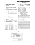
1
US 20130068846Al
(19) United States
(12) Patent Application Publication (10) Pub. No.: US 2013/0068846 A1
Bluestone
(54)
(43) Pub. Date:
WIRELESS CONTROLLED DAMPER
Publication Classi?cation
(71) Applicant: Alan Manufacturing Inc., Wooster, OH
(Us)
(51) Int. Cl.
F24F 11/053
(72) Inventor:
F24F 13/08
(52) US. Cl.
Richard A. Bluestone, May?eld
Heights, OH (US)
(US)
(2006.01)
(2006.01)
USPC .......................................... .. 236/493; 236/51
(57)
(73) Assignee: Alan Manufacturing Inc., Wooster, OH
Mar. 21, 2013
ABSTRACT
A Wireless radial damper system includes at least one radial
damper having a motor connected thereto to rotate the radial
damperbetWeen an open position and a closed position inside
a duct. A receiver is connected to the motor for communicat
(21) Appl' NO" 13/624’210
ing With the motor via a Wireless signal. A Wireless thermostat
(22)
remote from the receiver sends the Wireless signal to the
receiver Which in turn operates the motor to control the radial
Filed:
Sep. 21, 2012
Related U‘s‘ Application Data
damper. The Wireless thermostat alloWs for the radial damper
to' be temperature controlled rather than user controlled. A
W1reless remote controller, a W1reless Wand or some other
(60)
Provisional application No. 61/626,122, ?led on Sep.
21, 2011.
type of Wireless device may be used in place of a Wireless
thermostat.
Patent Application Publication
Mar. 21, 2013 Sheet 1 0f 10
US 2013/0068846 A1
Patent Application Publication
Mar. 21, 2013 Sheet 2 0f 10
US 2013/0068846 A1
FIG-1B
APRIOTR
Patent Application Publication
Mar. 21, 2013 Sheet 3 0f 10
1316-2
PRIOR ART
Fla-3
PRIOR ART
US 2013/0068846 A1
Patent Application Publication
Mar. 21, 2013 Sheet 4 0f 10
US 2013/0068846 A1
#IUE
mLoQE
:2moEm
Patent Application Publication
Mar. 21, 2013 Sheet 5 0f 10
US 2013/0068846 A1
<mlwE #2moEm
Patent Application Publication
Mar. 21, 2013 Sheet 6 0f 10
US 2013/0068846 A1
mIwE
#2x25
Patent Application Publication
Mar. 21, 2013 Sheet 7 0f 10
US 2013/0068846 A1
36
FIG-6A
Patent Application Publication
Mar. 21, 2013 Sheet 8 0f 10
US 2013/0068846 A1
Patent Application Publication
Mar. 21, 2013 Sheet 9 0f 10
US 2013/0068846 A1
FIG-7A
Patent Application Publication
Mar. 21, 2013 Sheet 10 0f 10
US 2013/0068846 A1
FIG-7B
US 2013/0068846 A1
WIRELESS CONTROLLED DAMPER
CROSS-REFERENCE TO RELATED
APPLICATION
[0001] This application claims priority of US. Provisional
Application Ser. No. 61/626,122 ?led on Sep. 21, 2011.
BACKGROUND OF THE INVENTION
[0002]
[0003]
1. Field of the Invention
The present invention relates to radial damper sys
Mar. 21,2013
ably higher such as vaulted ceilings), a person must use a step
ladder or some other device to be able to reach the termination
?xture. Once Within reach, a cover of the termination ?xture
must be removed in order to grant access to the end of the
rotary actuation cable. After the cover of termination ?xture is
removed, the person must use the torque inducing tool While
standing on the step ladder (or other similar device) to physi
cally turn the rotary actuation cable in order to adjust the
damper. This position can put strain on the person’s back due
to excessive reaching. Additionally, the person is susceptible
to falling off the step ladder since one or both hands are used
tems, and more particularly to a Wireless radial damper sys
to turn the torque inducing tool Which may result in serious
tem utilizing various types of motors operatively connected to
injury to the person. Thus, this type of mechanically activated
a Wireless thermostat or Wireless remote control.
damper includes a number of safety haZards for a person
[0004]
[0005]
When adjusting the damper.
2. Description of the PriorArt
Various types of damper systems are knoWn in the
art and are used to control air How in ventilation systems of
homes, apartments, Warehouses, buildings, etc.
[0006] Dampers vary the volume of air passing through an
air outlet, inlet, or duct but do not signi?cantly affect the
shape of the delivery pattern. Speci?cally, a radial damper
may be used to cut off central air conditioning (heating or
cooling) to an unused room, or to regulate it for room-by
room temperature and climate control. Its operation can be
manual, mechanical or can include a motoriZed gear and
coupling system. Radial dampers are advantageous When
there is limited space for installation in and around the air
duct. This is because the radial damper blades rotate clock
Wise or counterclockwise Within a single plane of the duct. On
the other hand, for example, a single round damper blade
must have enough space to rotate 90 degrees in order to fully
open and fully close the damper, and therefore this rotational
movement is not limited to a single plane inside the duct.
[0007] Manual radial dampers are turned by a handle on the
outside of a duct and thus one must have access to the outside
of the duct in order to adjust the damper. Since mo st ductWork
and ventilation systems are hidden above ?nished ceilings or
behind Walls, manual dampers are not easily accessible.
[0008]
Mechanically activated radial dampers are activated
in a number of Ways. One such Way is through the use of a
cable and is knoWn as a cable operated damper system, such
as those shoWn in US. Pat. Nos. 5,702,298 and 7,793,917. A
rotary actuation cable is used to mechanically rotate the
damper. In this system, the rotary actuation cable transmits
[0010] Another type of damper is a motoriZed gear and
coupling system, such as those disclosed in US. Publication
Nos. 2009011373 and 20090181611. These patent publica
tions disclose battery poWered damper systems controlled by
a hand held remote With a long cable from the motor of the
damper to a detachable electrical connector (i.e. a mini poWer
jack) for connection to a corresponding detachable electrical
connector of the hand held remote. Alternatively, the cable
from the motor can be connected to a Wall plate having
multiple electrical connections at a surface interface, and the
detachable electrical connector of the hand held remote is
then attached to one of the detachable electrical connectors at
the surface interface to control the damper. Use of these types
of detachable electrical connectors requires a person to physi
cally plug or unplug the electrical connectors.
[0011] If the hand held remote is connected directly to the
motor of the damper, the cable of the remote control Will be
exposed at the ceiling, Wall, vent, etc. to Wherever the remote
control is stored. This is very unsightly because the cable is
visible and hanging from the ceiling, Wall, vent, etc. Addi
tionally, exposed cables can also be a potential shock haZard.
When operated, the user must be careful not to pull the hand
held remote farther than the cable Will reach, since this results
in the cable being disconnected or torn from the motor. If this
happens, the person must reconnect the cable to the motor
Which can be tedious and time consuming since the motor is
located at the damper, Which is not easily accessible.
[0012] There are also draWbacks to a system Where the
cable from the motor is attached to a detachable electrical
torque from a remote torque inducing tool (i.e. a nut driver, a
screWdriver, or a knob) to a damper regulator for regulating
the damper. The rotary actuation cable is attached to the
damper using a cable bracket. Another cable bracket may be
used to secure the other end of the rotary actuation cable
outlets, and the other cable from the hand held remote is then
attached to the detachable electrical connection at the surface
interface to the respective jack or outlet Which controls the
Where the torque inducing tool is used to operate the damper,
Which is remote from the damper. This latter end of the rotary
actuation cable is typically accessible through a ceiling in
trical connection at the surface interface is usually attached at
the ceiling, Wall, vent etc. Such location is usually at a height
order to use the torque inducing tool to control the damper.
The actuation cable may also be accessible through a Wall,
vent cover, etc., although such areas are usually close to the
ceiling since the rotary actuation cable cannot be located very
far from the damper in order for rotary actuation cable to
function. A cable termination ?xture can be used to cover up
this end of the rotary actuation cable at the ceiling, Wall, vent
cover, etc.
[0009]
In order to adjust the mechanically activated damper
connection at a surface interface having one or more jacks or
damper to be adjusted. In this instance, the detachable elec
Where a person cannot reach Without the use of an elevating
device such as a stepladder, or some type of reaching tool.
Once Within reach, a cover of the surface interface must be
removed in order to grant access to the one or more jacks or
outlets. Additionally, if the surface interface includes more
than one j ack or outlet, the person must determine Which jack
or outlet controls the damper to be adjusted, Which may
require consulting With a user manual to properly determine
Which jack or outlet controls the damper to be adjusted. As
described above, a person must be able to reach the termina
tion ?xture at the ceiling, Wall, vent cover, etc. Since most
noted earlier With respect to systems having mechanically
ceilings are at least eight feet high (and sometimes consider
danger of falling. Thus, the motorized gear and coupling
activated dampers, this can cause back strain and presents the
US 2013/0068846 A1
system dampers also includes problems and safety hazards
for a person When adjusting the damper.
[0013] One major disadvantage of all of the above activated
radial dampers is that they are only manually controlled by a
person. Thus, a person must physically control the opening
and closing of the radial damper based on “feel.” In other
Words, the person controls the radial damper based on the
temperature that he or she “feels” in the room and is not based
on a speci?c temperature reading according to a thermostat.
Thus, these radial dampers according to the prior art are not
temperature controlled since there is no temperature reading
associated With the adjustment of the radial damper.
[0014] Accordingly, there is a need in the art of damper
systems for a device Which can control the damper remotely
Without the use of cables or Wires. Additionally, there is a
need for a Wireless damper system Which can be controlled at
normal user heights Without the need of a step ladder or other
similar device. There is also a need for a Wireless damper
system Which can be temperature controlled Without the need
for a user to physically open or close the radial damper. Such
a Wireless damper system Would utiliZe a Wireless thermostat
Which is programmable and easily accessible on a Wall or
other similar surface. A Wireless remote control, Wireless
Wand or other Wireless remote control device could also be
used in place of a thermostat.
[0015] As can be seen from the foregoing, a need exists for
Mar. 21,2013
[0025] The foregoing objects are achieved according to the
preferred embodiments of the invention by the provision of a
Wireless damper system Which can remotely adjust the
damper Without the use of cables or Wires.
BRIEF DESCRIPTION OF THE DRAWINGS
[0026] Other characteristics and advantages of the present
invention Will emerge from reading the detailed description
hereinbeloW of nonlimiting embodiments of the invention,
and examining the attached draWings Wherein:
[0027]
FIG. 1A is a perspective vieW of a radial damper
assembly according to the prior art shoWing the radial damper
blade in a fully open position and a cable running to a panel.
[0028] FIG. 1B is a perspective vieW of the damper assem
bly of FIG. 1A shoWing the damper blades in a closed posi
tion.
[0029]
FIG. 2 is a perspective vieW of a Wired 8-position
panel layout according to the prior art shoWing the connection
of a cable.
[0030]
FIG. 3 is a perspective vieW of a single position
panel layout according to the prior art shoWing the connection
of a cable.
[0031]
FIG. 4 is a perspective vieW of a Wired panel and a
hand-held controller according to the prior art shoWing the
cable connection betWeen the same.
a Wireless damper system Which eliminates the above-men
tioned problems, limitations and disadvantages of conven
[0032] FIG. 5A is perspective vieW of a radial damper
according to the prior art shoWing the damper blades in a fully
tional mechanically activated dampers and conventional
open position and a cable running to a panel.
[0033] FIG. 5B is a perspective vieW ofthe damper assem
motorized gear and coupling dampers. It is to this need that
the present invention is directed.
bly of FIG. 5A shoWing the damper blades in a fully closed
SUMMARY OF THE INVENTION
position and a cable running to a panel.
[0034] FIG. 6A is a perspective vieW a Wireless radial
[0016]
As described in the Description of the Prior Art,
various types of damper systems are knoWn in the art and can
be activated in a number of Ways to adjust the damper. Such
dampers systems require numerous steps by a user in order to
adjust the damper including potential safety haZards to the
user.
[0017] An object of the present invention is to provide a
Wireless damper system Which can be remotely operated from
virtually anyWhere in a home or building.
[0018] Another object of the present invention is to provide
a Wireless damper system Which is easier to install than pre
vious damper systems.
[0019] Still another object of the present invention is to
provide a Wireless damper system Which can control multiple
dampers.
[0020] Yet another object of the present invention is to
provide a Wireless damper system Which can be operated
from a Wireless remote control.
[0021]
Another object of the present invention is to provide
a Wireless damper Which is temperature controlled Without
damper according to the present invention shoWing the
damper blades in a fully open position.
[0035] FIG. 6B is an exploded perspective vieW of the
Wireless radial damper of FIG. 6A shoWing the various parts
of the Wireless radial damper.
[0036]
FIG. 7A is a perspective vieW a Wireless radial
damper assembly according to the present invention shoWing
the damper blades in a fully open position in a duct.
[0037] FIG. 7B is a perspective vieW of the Wireless damper
assembly of FIG. 7A shoWing a Wireless thermostat sending
a signal to the Wireless damper With an electronics cover
removed from the damper assembly.
DETAILED DESCRIPTION OF THE PREFERRED
EMBODIMENT
[0038] Disclosed according to the present invention is a
Wireless controlled damper system. The Wireless controlled
damper system can be operated by a Wireless remote control,
a Wireless thermostat, a Wireless Wand or any other type of
Wireless device having means to operate a motor of the
the need for a user to physically open or close the damper.
damper. In other Words, the Wireless remote control, the Wire
[0022] A further object of the present invention is to pro
vide a Wireless damper system Which can be operated by a
Wireless thermostat.
[0023] Another object of the present invention is to provide
less thermostat, the Wireless Wand, etc. does not have a Wire or
a Wireless damper system Which does not require the use of an
elevating device, or reaching device to adjust the damper.
[0024] Still yet another object of the present invention is to
provide a Wireless damper system Which can be used Without
requiring access by the user to the damper(s) or items for
adjusting the damper(s).
cable connected directly or indirectly from it to the damper,
and speci?cally to the motor of the damper. Alternatively, the
damper assembly can be controlled With a motor Which con
trols a normally Wired thermostat or Zone control panel.
[0039] With reference to FIGS. 6A to 7B, a temperature
controlled Wireless radial damper system 10 is disclosed.
Damper system 10 includes a radial damper 30, a motor 50, a
receiver 70 and a thermostat 90. Radial damper 30 includes
multiple “boW tie-shaped” blades 32 Which rotate about a
US 2013/0068846 A1
central shaft 34. In a fully open position shown in FIG. 7A
With a vertical blade axis, blades 32 are stacked one on top of
Mar. 21,2013
RF receiver 70, motor 50 of radial damper 30 is activated to
control the position of damper blades 32. The RF remote
another. In a fully closedposition shoWn in FIG. 7B, blades 32
control signal is advantageous because Walls, comers, etc. do
are adjacent each other and not stacked one on top of another.
not impede the transmission of the radio Waves.
To achieve the fully closed position, each blade 32 rotates one
[0045]
full blade position further than the previous adjacent blade as
is knoWn in the art of radial dampers based upon the rotation
ferred embodiment has a range of roughly 100 feet. In other
Words, the Wireless remote control does not have to be in the
The RF remote control signal according to the pre
of central shaft 34.
line-of-sight of the RF receiver of the damper system. There
[0040]
fore, a user can control the operation of the damper assembly
Without connection betWeen the Wireless remote control and
the RF receiver. Thus, the remote radio frequency control
A U-shaped bracket 36 is used for mounting radial
damper 30 inside a duct. U-shaped bracket 36 includes a hole
38 in the middle of bracket to alloW central shaft 34 to pass
therethrough. U-shaped bracket 36 is attached to a round
starter collar 40. The length of U-shaped bracket 36 is
approximately the same as the inside diameter of round
starter collar 40. U-shaped bracket 36 attaches to round starter
collar 40 using rivets or other knoWn fasteners. Round starter
collar 40 (and radial damper 30) is attached to a duct (not
shoWn) using techniques knoWn in the art such as by riveting.
[0041] After central shaft 34 passes through U-shaped
bracket, central shaft 34 connects to motor 50 via a motor
shaft 52. Motor 50 includes motor Wires 54 Which connect to
a receiver 70 as further described beloW. The motor used With
the present invention can include various types of different
motors knoWn in the art, and can be synchronous or geared.
The motor is typically rated at 24 volt but can also include 120
volt. Although various types of motors are knoWn in the prior
art for use With dampers, such dampers are single blade
could be around a corner, in a different room or even a dif
ferent ?oor. In the alternative, other types of signals can be
used besides RF signals. For example, an infrared ((“IR”)
signal and others knoWn in the art could be used as Well.
HoWever, an IR signal usually does not have the range of an
RF signal and the IR signal of the IR remote control must be
in the line of sight of the IR motor control. Therefore, an RF
signal is preferred.
[0046]
In the present embodiment, the RF remote control is
thermostat 90 as shoWn in FIG. 7B. Thermostat 90 is adjust
able and programmable to control the temperature of a home,
o?ice room or building through a heating ventilation and air
conditioning (HVAC) system such as a furnace, boiler, air
conditioner, etc. as is knoWn in the art. Thermostat 90
includes an RF emitter (not shoWn) Which sends an RF signal
to receiver 70 When the HVAC system turns on and off based
dampers or rectangular dampers Where the shaft connected to
the blade(s) only needs to rotate 90 degrees to open or close
the blades. Therefore, most damper motors knoWn in the art
on the programmed temperature of the thermometer inside
thermostat 90. When receiver 70 receives the RF signal,
only have a rotation angle of 90 degrees. HoWever, radial
dampers require a shaft rotation of 180 degrees to achieve the
fully open or fully closed positions. Therefore, motor 50 of
the opening or closing of radial blades 32 of damper 30.
motor 50 operates to rotate central shaft 34 Which activates
the present invention must have a rotation angle of 180
Therefore, damper system 10 is temperature controlled since
it automatically adjusts damper 30 to a fully open position, a
fully closed position, or some position betWeen the fully open
degrees.
and fully closed positions. Of course damper system 10 can
Motor 50 Was modi?ed to rotate from 90 degrees to
also be controlled based on a user using a portable RF remote
180 degrees in order to open and close radial damper 30. The
180 degree rotation is achieved by adjusting the cams inside
controller or by manually adjusting the temperature setting on
[0042]
the motor that activate the “open” or “close” limit sWitches at
thermostat 90.
[0047] Receiver 70 can be mounted in a number of different
places near the damper assembly, and is preferably located
the end of the travel (of the cam) Which stops the motor. For
example, motor 50 could be Model A250-MOC-l 80 made by
eControls, Inc. of Laguna Hills, Calif. Another type of motor
that may be used is an econo spring-retum motor (not shoWn).
This type of motor includes an automatic spring-retum for the
damper to return to the fully closed position.
[0043] Although motor 50 in the present embodiment is
located inside the duct and thus inside the air stream, it may be
mounted to the damper assembly 10 using a bracket or “take
off” 80 knoWn in the art. Such take-offs are manufactured by
preferable for motor 50 to be located outside of the air stream
in order to reduce any blockage of air in the duct. If motor 50
is located outside of air stream, a short cable (not shoWn) Will
need to connect from motor shaft 54 outside of the duct to
mount receiver 70 to take-off 80.
outside of the airstream and therefore on the outside of
damper assembly 10. As shoWn in FIG. 7A, receiver 70 is
Duratite and Acitvent and can be made from a number of
materials including plastic and galvaniZed steel. Take-off 80
is mounted to the outside of round starter collar 40 using
fasteners knoWn in the art such as rivets (not shoWn). Addi
tional fasteners, such as screWs (not shoWn), are used to
central shaft 34 of radial damper 30 inside of the duct. Upon
[0048] Receiver 70 is not limited to any speci?c location
With respect to damper assembly 10. Receiver 70 may be
rotation of motor shaft 54, cable Will rotate Which in turn Will
connected to the same poWer source or transformer for motor
rotate central shaft 34 inside damper assembly 10.
[0044] Receiver 70 in its preferred form includes a radio
frequency (“RF”) receiver Which is attached to motor 50 by
70 and to motor 50 can come from the same transformer (not
motor Wires 54 as shoWn in FIGS. 7A-7B. RF receivers are
volts and are considered to be of loW amperage. Therefore, the
Well knoWn in the art and various types can be used With the
present invention. RF receivers pick up an RF signal or radio
more than one motor 50 and receiver 70 for additional damp
Wave from an RF remote control and convert it to an electrical
ers.
50 of damper assembly 10. Thus, the Wires from the receiver
shoWn). Both receiver 70 and motor 50 typically require 24
transformer could easily supply poWer for multiple units, i.e.
signal. The electrical signal then runs through Wires and a
[0049]
connecting block, to radio frequency emitters (RF emitter)
control panel for controlling multiple radial dampers in mul
that reproduce the original radio frequency remote control
signal. When the RF remote control signal is received by the
tiple rooms (i.e. Zones) of a home or building. In this scenario,
multiple receivers are Wired in parallel or in series together in
The present invention can also be used With a Zone
US 2013/0068846 A1
Mar. 21,2013
order to communicate With a single thermostat. If different
at least one radial damper including a central shaft and
temperatures are desired in the different rooms or Zones, an
additional thermostat is installed in each room or Zone. There
radial blades operatively connected to said central shaft,
said radial blades being movable betWeen an open position
for opening the air inlet and air outlet, and a closed
fore, the radial damper in one Zone is controlled by a desired
temperature and the radial damper in another Zone is con
trolled by a different desired temperature. Thus, a Zone con
trolled system alloWs for the independent adjustment of the
temperature in each Zone.
[0050]
In another possible embodiment of the present
invention not shoWn, a Wireless remote control, a Wireless
Wand or any other type of Wireless device could be used in
place of thermostat 70. The Wireless remote control, Wireless
Wand or other type of Wireless device Would function in a
similar manner as thermostat 70. That is, Wireless remote
control, Wireless Wand or other type of Wireless device Would
include an RF emitter Which Would send an RF signal from
the Wireless remote control, a Wireless Wand, or other Wireless
device to receiver 70, and the damper system Would operate in
the same manner as previously discussed.
[0051] Thermostat 70 or Wireless remote control, Wireless
Wand, or other Wireless can display additional information
other than temperature, such as battery life, identi?cation of
the damper being controlled, the position of the dampers
relative to the fully open/closed position, and other informa
tion. To accommodate these additional features, thermostat
70 or Wireless remote control, Wireless Wand, or other Wire
less may be provided With a visual or audible display. Ther
mostat 70 or Wireless remote control, Wireless Wand, or other
Wireless may also include a memory to store data.
[0052]
Having described the invention, it Will be apparent
to those skilled in the art that alterations and modi?cations
may be made Without departing from the spirit and scope of
the invention limited only by the appended claims.
I claim:
1. A Wireless radial damper system for use With a duct
having an air inlet and air outlet inside the duct, said Wireless
radial damper system comprising:
position for closing the air inlet and air outlet;
a motor operatively connected to said central shaft for
moving said radial blades betWeen the open position, the
closed position or a position betWeen the open and
closed positions;
a receiver operatively connected to said motor for receiving
a Wireless signal to control said motor; and
a programmable Wireless thermostat for selectively trans
mitting the Wireless signal to said receiver,
Wherein said radial damper system is capable of being
temperature controlled based on the programming of
said Wireless thermostat.
2. A Wireless radial damper system according to claim 1,
Wherein said motor is an econo spring return motor.
3. A Wireless radial damper system according to claim 1,
Wherein said motor is located Within the air inlet and outlet of
the duct.
4. A Wireless radial damper system according to claim 1,
Wherein said motor is located outside of the air inlet and outlet
of the duct.
5. A Wireless radial damper system according to claim 1
and further comprising a take off operatively connected to the
outside of the duct for mounting said receiver outside of the
duct.
6. A Wireless radial damper system according to claim 4
and further comprising a cable connected from said motor
outside of the duct to said central shaft inside of the duct.
7. A Wireless radial damper system according to claim 1
Wherein said motor has a rotation angle of 180 degrees.
8. A Wireless radial damper system according to claim 1
Wherein said thermostat is a Wireless remote controller.
9. A Wireless radial damper system according to claim 1
Wherein said thermostat is a Wireless Wand.
*
*
*
*
*