1
OB272-1.qxp
02.1.26 1:22 PM
Page 1
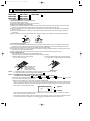
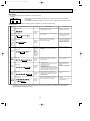
Revision:
● MUH-18RV- E2 has been added.
MUH-18RV- E1 ➔ MUH-18RV- E2
•Path of outdoor heat exchanger has changed.
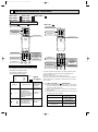
SPLIT-TYPE, HEAT PUMP AIR CONDITIONERS
No. OB272
REVISED EDITION-A
SERVICE MANUAL
Wireless type
Models
MSH-18RV MSH-24RV MSH-30RV -
E1
(WH)
E1
(WH)
E1
(WH)
·
·
·
·
MUH-18RV
MUH-18RV
MUH-24RV
MUH-30RV
-
E1
E2
E1
E1
CONTENTS
MSH-18RV MSH-24RV -
E1
E1
1. TECHNICAL CHANGES ····································2
2. PART NAMES AND FUNCTIONS······················2
3. SPECIFICATION·················································6
4. NOISE CRITERIA CURVES ·······························8
5. OUTLINES AND DIMENSIONS ······················ 10
6. WIRING DIAGRAM ··········································13
7. REFRIGERANT SYSTEM DIAGRAM ··············17
8. PERFORMANCE CURVES ······························20
9. MICROPROCESSOR CONTROL ····················36
10. SERVICE FUNCTIONS·····································50
11. TROUBLESHOOTING ······································52
12. DISASSEMBLY INSTRUCTIONS·····················71
13. PARTS LIST······················································79
14. OPTIONAL PARTS···········································88
•Refer to the Service Manual OB185 REVISED EDITION C when MSH-18RV- E1 is connected
with MXZ-32NV- E1 or MXZ-32NV- E2 as multi system units.
•Refer to the Service Manual OB227 REVISED EDITION-B when MSH-18RV- E1 is connected
with MXZ-32RV- E1 as multi system units.
•Refer to the Service Manual OB254 when MSH-18RV- E1 is connected with MXZ-32SV- E1 as
multi system units.
OB272-1.qxp
1
02.1.26 1:22 PM
Page 2
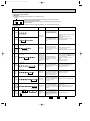
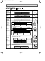
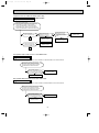
TECHNICAL CHANGES
MSH-18NV - E4 ➔MSH-18RV - E1
MSH-24NV - E2 ➔MSH-24RV - E1
1. Remote controller has changed.
• SLEEP MODE function has removed.
• ECONO COOL operation has added.
• SWING button is removed, but SWING MODE function is available by VANE CONTROL button.
MSH-30RV - E1
New model
MUH-18NV - E4 ➔MUH-18RV - E1
1. Outdoor model name has changed.
MUH-18RV - E1 ➔MUH-18RV - E2
1. Path of outdoor heat exchanger has changed.
MUH-24NV - E2 ➔MUH-24RV - E1
1. Outdoor deicer P.C. board has changed.
2. Ball valve has changed to stop valve.
3. Thermostat has changed to ambient temperature thermistor.
MUH-30RV - E1
New model
2
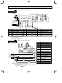
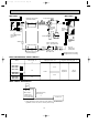
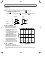
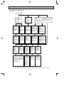
PART NAMES AND FUNCTIONS
,
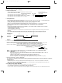
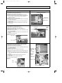
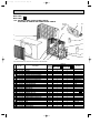
INDOOR UNIT
MSH-18RV - E1
MSH-24RV - E1
Grille
MSH-30RV - E1
Air inlet
Air cleaning filter (option)
(White bellows type)
Deodrizing filter (option)
(Gray sponge type)
Remote control
receiving section
Front panel
Horizontal vane
Air filter
Remote controller
Vertical vanes
Operation section
(When the grille is opened)
MSH-18RV- E1
MSH-24RV- E1
Display section
MSH-18RV- E1
MSH-24RV- E1
Operation indicator lamp
Emergency operation switch
MSH-30RV- E1
Receiving section
Operation indicator lamp
MSH-30RV- E1
Emergency operation switch
2
Operation Indicator
Receiving section
OB272-1.qxp
02.1.26 1:49 PM
Page 3
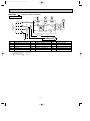
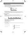
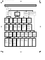
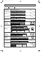
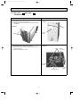
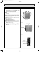
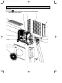
OUTDOOR UNIT
MUH-18RV MUH-18RV -
MUH-24RV MUH-30RV -
E1
E2
Air inlet
(back and side)
Piping
Drainage hose
Air outlet
Drain outlet
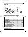
ACCESSORIES
Indoor unit
1
2
3
4
5
6
7
Installation plate
Installation plate fixing screw 4 o 25 mm
Remote controller mouting hardware
Fixing screw for 3 o 3.5 o 1.6 mm (Black)
Battery (AAA) for remote controller
Wireless remote controller
Felt tape (Used for left or left-rear piping)
E1
E1
1
6
1
2
2
1
1
MSH-30RV-
E1
1
7
1
2
2
1
1
Outdoor unit
MUH-18RVMUH-18RV8
9
Drain socket
Drain cap {33
Drain cap {16
1
2
1
3
E1
E2
MUH-24RVMUH-30RV1
6
—
E1
Air outlet
Air inlet
MSH-18RVMSH-24RV-
E1
E1
E1
OB272-1.qxp
02.1.26 1:22 PM
Page 4
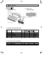
REMOTE CONTROLLER
MSH-18RV - E1
MSH-24RV - E1
Signal transmitting section
Operation display section
PM
OPERATE /STOP
(ON /OFF)button
AM
TOO
ON/OFF WARM
TOO
COOL
TEMPERATURE buttons
Open the front lid.
CLOCK
PM
AM
TOO
ON/OFF WARM
VANE CONTROL button
TOO
COOL
FAN
STOP
VANE
START
I FEEL COOL
FAN SPEED CONTROL button
OFF-TIMER button
HEAT DRY
ON-TIMER button
MODE
HR.
ECONO COOL
MIN.
OPERATION SELECT button
ECONO COOL button
HR. button
MIN. button
(TIME SET button)
RESET CLOCK
CLOCK SET button
RESET button
4
OB272-1.qxp
02.1.26 1:22 PM
Page 5
REMOTE CONTROLLER
MSH-30RV - E1
Signal transmitting section
Operation display section
PM
OPERATE /STOP
(ON /OFF)button
AM
TOO
ON/OFF WARM
TOO
COOL
TEMPERATURE buttons
Open the front lid.
CLOCK
PM
AM
TOO
ON/OFF WARM
VANE button
(Horizontal vane button)
TOO
COOL
FAN
STOP
VANE
START
I FEEL COOL
FAN SPEED CONTROL button
OFF-TIMER button
HEAT DRY
ON-TIMER button
MODE WIDE VANE
HR.
OPERATION SELECT button
ECONO COOL
LONG
ECONO COOL button
MIN.
HR. button
MIN. button
(TIME SET button)
RESET CLOCK
CLOCK SET button
WIDE VANE button
(Vertical vane button)
LONG button
RESET button
5
OB272-1.qxp
3
02.1.26 1:22 PM
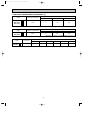
Page 6
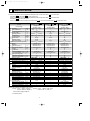
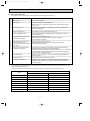
SPECIFICATION
W1. Refer to the Service Manual OB185 REVISED EDITION C when MSH-18RV- E1 is connected with
MXZ-32NV- E1 or MXZ-32NV- E2 as multi system units.
Refer to the Service Manual OB227 REVISED EDITION-B when MSH-18RV- E1 is connected with
MXZ-32RV- E1 as multi system units.
Refer to the Service Manual OB254 when MSH-18RV- E1 is connected with MXZ-32SV- E1 as multi system units.
Indoor model
Function
Power supply
Special
remarks
Fan
Electrical
Compressor
motor
data
Special
remarks
Fan
motor
Electrical
data
Capacity
Capacity
kW
Dehumidification
r/h
Air flow(High/Med.w/Low w ) K /h
Power outlet
A
Running current
A
Power input
W
Auxiliary heater
A(kW)
Power factor
%
Starting current
A
Fan motor current
A
Coefficient of performance(C.O.P)
Model
Winding
"
resistance(at20:)
Dimensions WOHOD
mm
Weight
kg
Air direction
Sound level(High/Med.w /Low w)
dB
Fan speed(High/Med.w /Loww ) rpm
Fan speed regulator
Thermistor RT11(at25:)
k"
Thermistor RT12(at25:)
k"
Outdoor model
Capacity Air flow(High/Low w)
K /h
Compressor motor current
A
Fan motor current
A
Model
Output
W
Winding
"
resistance(at20:)
Model
Winding
"
resistance(at20:)
Dimensions WOHOD
mm
Weight
kg
Sound level(High)
dB
Fan speed(High/Low w)
rpm
Fan speed regulator
Refrigerant filling
kg
capacity(R22)
Refrigerating oil (Model)
cc
Thermistor RT61(at0:)
k"
Thermistor RT63(at0:)
k"
MSH-18RV - E1
Cooling
Heating
Single phase
220-240V, 50Hz
5.1
5.4
2.5
—
756/654 w/546 w
15
9.4-9.2
9.2-9.0
2,030-2,120 1,980-2,070
—
98-96
52-58
0.25
2.51-2.41
2.73-2.61
RA4V27-EF
WHT-BLK 183.8
BLK-RED 250.5
1,015O320O190
14
5
42/39w /34 w
1,180/1,040 w/900 w
3
10
10
MUH-18RV - E1 E2
High:2,142-2,244
8.76-8.56
8.56-8.36
0.39
PH-36VPET
1,600
C-R 1.03
C-S 2.04
RA6V50-OG
WHT-BLK 116.4
BLK-RED 111.0
850o605o290
54
52
High:810-845
1
w1.MSH-18RV - E1
Cooling
Heating
Single phase
220-240V, 50Hz
—
—
756/654w /546 w
10
0.28
60
—
97-89
—
0.25
—
RA4V27-EF
WHT-BLK 183.8
BLK-RED 250.5
1,015O320O190
14
5
42/39 w/34w
1,180/1,040 w/900 w
3
10
10
—
—
—
—
—
—
—
—
—
—
—
MSH-24RV - E1
Cooling
Heating
Single phase
220-240V, 50Hz
6.0
6.2
3.1
—
816/726 w/630w
25
12.6-11.7
11.5-11.0
2,720-2,750 2,470-2,580
—
98
59
0.29
2.21-2.18
2.51-2.40
RA4V27-EE
WHT-BLK 183.3
BLK-RED 250.5
1,015O320O190
14
5
45/42 w/38 w
1,260/1,140 w/1,020 w
3
10
10
MUH-24RV - E1
2,640-2,760/2,100-2,250w
11.73-10.83 10.63-10.13
0.58
NH-47VMDT
2,200
C-R 0.96
C-S 2.07
RA6V85-AA
WHT-BLK 62.7 BLK-YLW 30.2
YLW-RED 62.9
870o850o295
72
53
720-750/570-610 w
2
1.65
—
2.40
900 (MS32N1)
33.18
—
—
—
—
1,200 (MS32N1)
33.18
33.18
—
—
—
NOTE: Test conditions are based on JIS C 9612.
Cooling : Indoor DB27°C WB19°C
Heating : Indoor DB20°C WB 15.5°C
Outdoor DB35°C WB(24°C)
Outdoor DB 7°C WB 6°C
Indoor-Outdoor piping length 5m
w Reference value
6
02.1.26 1:22 PM
Page 7
Indoor model
Function
MSH-30RV -
Heating
Single phase
220-240V, 50Hz
Power supply
25
Special
remarks
16.3-15.8
3,520-3,560
15.3-15.5
3,300-3,460
—
98-94
98-93
82-84
0.33-0.35
2.73-2.70
2.52-2.40
RC4V40-AA
WHT-BLK 138.2
BLK-RED 159.0
1,100O325O227
16
5
47/43 w /39 w
1,280/1,130w /970 w
1,280/1,150 w/1,020 w
3
10
10
10
MUH-30RV -
E1
2,880-3,000/1,380-1,560w
15.41-14.87
2,880-3,000/1,380-1,560w
14.41-14.57
0.56-0.58
NH-56VNHT
2,700
C-R 0.66
C-S 1.58
RA6V75-AA
WHT-BLK 62.8 BLK-YLW 55.9
YLW-RED 26.0
870o850o295
79
55
790-820/420-450 w
2
Fan
motor
Compressor
Electrical
data
9.6
—
960/834w /732 w
8.3
4.5
960/822w /684 w
Fan
motor
Electrical
data
Capacity
kW
Capacity
R/h
Dehumidification
Air flow(High/Med.w/Low w ) K /h
A
Power outlet
A
Running current
W
Power input
A(kW)
Auxiliary heater
%
Power factor
A
Starting current
A
Fan motor current
Coefficient of performance(C.O.P)
Model
Winding
"
resistance(at20:)
mm
Dimensions WOHOD
kg
Weight
Air direction
dB
Sound level(High/Med.w/Low w )
Fan speed(High/Med.w /Low w ) rpm
Fan speed regulator
k"
Thermistor RT11(at25:)
k"
Thermistor RT12(at25:)
k"
Thermistor RT13(at25:)
Outdoor model
K /h
Capacity Air flow(High/Loww )
A
Compressor motor current
A
Fan motor current
Model
W
Output
Winding
"
resistance(at20:)
Model
Winding
"
resistance(at20:)
mm
Dimensions WOHOD
kg
Weight
dB
Sound level(High)
rpm
Fan speed(High/Low w)
Fan speed regulator
Refrigerant filling
kg
capacity(R22)
cc
Refrigerating oil (Model)
k"
Thermistor RT61(at0:)
k"
Thermistor RT62(at25:)
k"
Thermistor RT63(at0:)
E1
Cooling
Special
remarks
OB272-1.qxp
2.30
1,200 (MS32N1)
33.18
231.44
33.18
NOTE: Test conditions are based on JIS C 9612.
Cooling : Indoor DB27°C WB19°C
Heating : Indoor DB20°C WB 15.5°C
Outdoor DB35°C WB(24°C)
Outdoor DB 7°C WB 6°C
Indoor-Outdoor piping length 5m
w Reference value
7
OB272-1.qxp
02.1.26 1:22 PM
Page 8
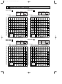
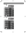
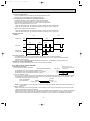
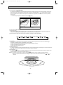
NOISE CRITERIA CURVES
4
MSH-18RV- E1
MSH-24RV- E1
NOTCH
SPL(dB(A))
High
42
LINE
80
70
NC-70
60
NC-60
50
NC-50
40
NC-40
30
NC-30
20
10
APPROXIMATE
THRESHOLD OF
HEARING FOR
CONTINUOUS
NOISE
63
NC-20
125
250
500
1000
2000
4000
NC-70
60
NC-60
50
NC-50
40
NC-40
30
NC-30
20
10
APPROXIMATE
THRESHOLD OF
HEARING FOR
CONTINUOUS
NOISE
63
125
SPL(dB(A))
High
52
LINE
500
1000
2000
4000
8000
60
NC-60
50
NC-50
40
NC-40
30
NC-30
APPROXIMATE
THRESHOLD OF
HEARING FOR
CONTINUOUS
NOISE
NC-20
250
500
1000
2000
4000
NOTCH
SPL(dB(A))
High
53
LINE
Test conditions,
Cooling : Dry-bulb temperature 35: Wet-bulb temperature 24:
Heating : Dry-bulb temperature 7: Wet-bulb temperature 6:
90
OCTAVE BAND SOUND PRESSURE LEVEL, dB re 0.0002 MICRO BAR
OCTAVE BAND SOUND PRESSURE LEVEL, dB re 0.0002 MICRO BAR
NOTCH
NC-70
125
250
MUH-24RV- E1
70
63
NC-20
BAND CENTER FREQUENCIES, Hz
80
10
45
70
8000
Test conditions,
Cooling : Dry-bulb temperature 35: Wet-bulb temperature 24:
Heating : Dry-bulb temperature 7: Wet-bulb temperature 6:
90
20
High
LINE
80
BAND CENTER FREQUENCIES, Hz
MUH-18RV- E1
MUH-18RV- E2
SPL(dB(A))
Test conditions,
Cooling : Dry-bulb temperature 27: Wet-bulb temperature 19:
Heating : Dry-bulb temperature 20: Wet-bulb temperature 15.5:
90
OCTAVE BAND SOUND PRESSURE LEVEL, dB re 0.0002 MICRO BAR
OCTAVE BAND SOUND PRESSURE LEVEL, dB re 0.0002 MICRO BAR
Test conditions,
Cooling : Dry-bulb temperature 27: Wet-bulb temperature 19:
Heating : Dry-bulb temperature 20: Wet-bulb temperature 15.5:
90
NOTCH
80
70
NC-70
60
NC-60
50
NC-50
40
NC-40
30
NC-30
20
10
8000
BAND CENTER FREQUENCIES, Hz
APPROXIMATE
THRESHOLD OF
HEARING FOR
CONTINUOUS
NOISE
63
125
NC-20
250
500
1000
2000
4000
BAND CENTER FREQUENCIES, Hz
8
8000
OB272-1.qxp
02.1.26 1:22 PM
Page 9
MSH-30RV- E1
NOTCH
SPL(dB(A))
High
47
LINE
OCTAVE BAND SOUND PRESSURE LEVEL, dB re 0.0002 MICRO BAR
Test conditions,
Cooling : Dry-bulb temperature 27: Wet-bulb temperature 19:
Heating : Dry-bulb temperature 20: Wet-bulb temperature 15.5:
90
80
70
NC-70
60
NC-60
50
NC-50
40
NC-40
30
NC-30
20
10
APPROXIMATE
THRESHOLD OF
HEARING FOR
CONTINUOUS
NOISE
63
NC-20
125
250
500
1000
2000
4000
8000
BAND CENTER FREQUENCIES, Hz
MUH-30RV- E1
NOTCH
SPL(dB(A))
High
55
LINE
OCTAVE BAND SOUND PRESSURE LEVEL, dB re 0.0002 MICRO BAR
Test conditions,
Cooling : Dry-bulb temperature 35: Wet-bulb temperature 24:
Heating : Dry-bulb temperature 7: Wet-bulb temperature 6:
90
80
70
NC-70
60
NC-60
50
NC-50
40
NC-40
30
NC-30
20
10
APPROXIMATE
THRESHOLD OF
HEARING FOR
CONTINUOUS
NOISE
63
125
NC-20
250
500
1000
2000
4000
8000
BAND CENTER FREQUENCIES, Hz
9
OB272-1.qxp
02.1.26 1:22 PM
5
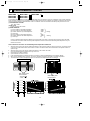
Page 10
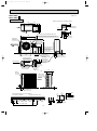
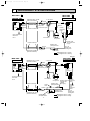
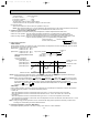
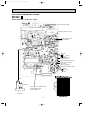
OUTLINES AND DIMENSIONS
Unit: mm
MSH-18RV - E1
MSH-24RV - E1
INDOOR UNIT
Indoor unit
4holes 11✕20
648
217
450
3
450
297
254
60
40
20
150
995
438
352
Wall hole [75
Installation plate
1015
190
5
320
Installation plate
{
Air in
50
775
190
58
19
Liquid line [8-0.5m
Gas line [12-0.43m
Insulation [50 O.D
[28 I.D
Drain hose [16
Insulation [28
Air out
162
Power supply cord
Lead to right 2m
Lead to left 1m
MUH-18RV- E1
MUH-18RV- E2
OUTDOOR UNIT
355
350
Air in
100m
mo
r mo
re
Drainage
3holes [33
Air out
re
r mo
mo
m
0
50
345
290
Air in
310
20
248
90
35
Drainage
hole [16.2
100mm or more
Wireless remote controller
50
30
Service panel
20
100
157
35-
292
30-
605
Liquid refrigerant
pipe joint
Refregerant pipe
(flared) [6.35
183
500
850
161
74
10
Gas refregerant
pipe joint
Refregerant pipe
(flared) [15.88
re
r mo
mo
m
0
0
1
350
mm
or m
ore
02.1.26 1:22 PM
Page 11
MSH-30RV - E1
Unit: mm
INDOOR UNIT
Installation plate
Indoor unit
7.5
173
98
414.5
414.5
173
Wall hole [ 75
225
1100
Installation plate
{
Air in
791
56
253
Air out
19
162
58
5
Wireless remote controller
11
Liquid line [ 9.52- 0.5m
Gas line [ 19-0.43m
Insulation [ 50 O.D
[ 32 I.D
Drain hose [ 16
(Connected part O.D)
Insulation [ 28
47
2.5
47
255.5
1068
315
98
325
OB272-1.qxp
OB272-1.qxp
02.1.26 1:22 PM
Page 12
MUH-24RV- E1
MUH-30RV- E1
Unit: mm
OUTDOOR UNIT
Outdoor Unit-Necessary surrounding clearance
200
39.5 27.5
330
362
Air intake
Air intake
Front opening
500
15
Air outlet
Note:Allow adequate
upper clearance
10
10
Terminal block for power line(MUH-30RV only)
870
10
Terminal block for indoor and outdoor unit connection
302
150
185
500
17
185
Service space
500
Outlet guide
installation hole
Handle for moving
Service panel
Handle for moving
553
2-12o23 Oval holes
(standard bolt M10)
45
Knock out hole
for front piping
(refrigerant,drainage
and wiring)
60
60
120
53
450
445
524
Knock out holes for
power line 2-[27
33
45
104
42
40
Refrigerant-pipe flared
connection [15.88
Refrigerant-pipe flared
connection [9.52
179
441
468
850
524
A
Knock out hole
for right piping
(refrigerant,drainage
and wiring)
Drain hole [33
Bottom
piping hole
2-U-shaped
notched
holes
Drain hole [33
7
A
Handle
for moving
295
24
Side air intake
33
Rear piping hole
R2
80
0
100
10
12
For 10 units or less
Standard bolt length
17
200
R6
1000
12
25 max.
Outdoor Unit-Necessary surrounding clearance
(Concentrated installation)
The upper side must be open.
R2
0
95
23
138
Rear fresh
air intake
65
Front right piping holesdetail figures
OB272-1.qxp
02.1.26 1:22 PM
6
Page 13
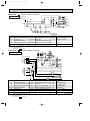
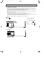
WIRING DIAGRAM
MSH-18RV - E1
MODEL WIRING DIAGRAM
INDOOR UNIT
TO OUTDOOR
L TB BRN
UNIT
CONNECTING
BRN
12V
3
200-240V~ 2
NR11
4
BLU
BLU
F12
WHT
BLU
2
BLU
1
CN201
3
1
BLU
52C
3
CN
112
IC141
TRANS
CIRCUIT BREAKER
FOR MULTI SYSTEM
TO OUTDOOR
UNIT
CONNECTING
C11
CN
101
GRN/YLW
RT11
3
MV
DISPLAY
RECEIVER
P.C. BOARD
P.C. BOARD
IC141
REMOTE
CONTROLLER
NAME
SYMBOL
INDOOR FAN CAPACITOR
CN
ELECTRONIC CONTROL P.C. BOARD 111
HYBRID IC
SYMBOL
NAME
RT12
INDOOR COIL TEMPERATURE THERMISTOR
MF
INDOOR FAN MOTOR (INNER FUSE)
TB
TERMINAL BLOCK
MV
VANE MOTOR
52C
CONTACTOR
SURGE ABSORBER
F11
FUSE (3.15A)
F12
THERMAL FUSE (93;)
NR11
VARISTOR
HIC1
DC/DC CONVERTER
RT11
ROOM TEMPERATURE THERMISTOR
VG79B021H01
NOTES: 1.About the outdoor side electric wiring refer to the outdoor unit electric wiring diagram for servicing.
2.Use copper conductors only. (For field wiring)
3.Symbols below indicate.
: Terminal block
: Connector
1
SR61
TAB21
RED
4
X62
TAB20
1
WHT
3
TRANS
WHT
1
2
NR61
2
MF
CN720
X62
IC881
220-240V~
BLU
CN721
F61
WHT
N
VLT
BLK
CN661
C65
CN730
RED
2
3
BLK
4
RED
ORN
WHT
BLK
CN711
DEICER P.C. BOARD
DSAR
GRN/YLW
FROM INDOOR UNIT
CONNECTING
TB
3
52C
BLK
21S4
RT61
VLT
MODEL WIRING DIAGRAM
MUH-18RV - E1
OUTDOOR UNIT
12V
MF
5
3
L
3
N
2
NAME
SYMBOL
DSAR
12V
GRN/YLW
DSAR
PE
CN
151
BRN
YLW
GRY
WHT
RED
BLK
4
2
1
LD1
CN
102
3
CN211
F11
POWER SUPPLY
CORD
~/N 220-240V
50Hz
RT12
CN
121
C11
N
HIC1
RED
WHT
NO
52C
COM
WHT
C1
BLU
C
RED
S
MC
R
BLK
SYMBOL
NAME
SYMBOL
NAME
C1
COMPRESSOR CAPACITOR
MC
COMPRESOR (INNER PROTECTOR)
TB
TERMINAL BLOCK
OUTDOOR FAN CAPACITOR
MF
R.V. COIL RELAY
C65
DSAR
F61
IC881
NAME
SYMBOL
OUTDOOR FAN MOTOR (INNER PROTECTOR)
X62
NR61
VARISTOR
21S4
R.V. COIL
FUSE (2A)
RT61
DEFROST THERMISTOR
52C
COMPRESSOR CONTACTOR
DC/DC CONVERTER
SR61
SOLID STATE RELAY
SURGE ABSORBER
NOTES: 1.About the indoor side electric wiring refer to the indoor unit electric wiring diagram for servicing.
2.Use copper conductors only. (For field wiring)
3.Symbols below indicate.
: Terminal block
: Connector
13
SG79J004H01
Page 14
21S4
TB
CN730
3
RED
1
CN661
N
VLT
MF
CN720
X62
SR61
TAB21
1
2
NR61
IC881
2
WHT
RED
WHT
4
X62
TAB20
1
2
3
3
TRANS
DSAR
220-240V~
BLU
52C
CN721
F61
WHT
GRN/YLW
FROM INDOOR UNIT
CONNECTING
12V
BLK
RT61
VLT
MODEL WIRING DIAGRAM
MUH-18RV - E2
OUTDOOR UNIT
C65
02.1.26 1:22 PM
BLK
OB272-1.qxp
BLK
4
RED
ORN
WHT
BLK
CN711
DEICER P.C. BOARD
WHT
NO
52C
COM
WHT
C1
BLU
C
RED
S
MC
R
BLK
SYMBOL
NAME
SYMBOL
NAME
C1
COMPRESSOR CAPACITOR
MC
COMPRESOR (INNER PROTECTOR)
TB
TERMINAL BLOCK
OUTDOOR FAN CAPACITOR
MF
R.V. COIL RELAY
C65
DSAR
F61
IC881
NAME
SYMBOL
OUTDOOR FAN MOTOR (INNER PROTECTOR)
X62
NR61
VARISTOR
21S4
R.V. COIL
FUSE (2A)
RT61
DEFROST THERMISTOR
52C
COMPRESSOR CONTACTOR
DC/DC CONVERTER
SR61
SOLID STATE RELAY
SURGE ABSORBER
NOTES: 1.About the indoor side electric wiring refer to the indoor unit electric wiring diagram for servicing.
2.Use copper conductors only. (For field wiring)
3.Symbols below indicate.
: Terminal block
: Connector
14
VG79B115H01
02.1.26 1:22 PM
Page 15
MSH-24RV - E1
MODEL WIRING DIAGRAM
INDOOR UNIT
TO OUTDOOR
UNIT
CONNECTING
TB
RED
N
220-240V~ 2
HIC1
BLU
BLU
F12
WHT
CN201
3
1
BLU
2
BLU
1
L
4
3
CN
112
IC141
52C
TRANS
BRN
CN
121
WHT
C11
DSAR
102
DSAR
GRN/YLW
CIRCUIT BREAKER
GRN/YLW
CN
101
ELECTRONIC CONTROL P.C. BOARD
3
MV
DISPLAY
RECEIVER
P.C. BOARD
P.C. BOARD
IC141
INDOOR FAN CAPACITOR
SURGE ABSORBER
REMOTE
CONTROLLER
NAME
SYMBOL
HYBRID IC
SYMBOL
NAME
RT12
INDOOR COIL THERMISTOR
MF
INDOOR FAN MOTOR (INNER FUSE)
TB
TERMINAL BLOCK
MV
VANE MOTOR
52C
CONTACTOR
F11
FUSE (3.15A)
F12
THERMAL FUSE (93;)
NR11
VARISTOR
HIC1
DC/DC CONVERTER
RT11
ROOM TEMPERATURE THERMISTOR
VG79B022H01
NOTES: 1.About the outdoor side electric wiring refer to the outdoor unit electric wiring diagram for servicing.
2.Use copper conductors only. (For field wiring)
3.Symbols below indicate.
: Terminal block
: Connector
MODEL WIRING DIAGRAM
MUH-24RV - E1
OUTDOOR UNIT
YLW
BLK
WHT
ORN
RED
RT63
YLW
BLK
WHT
6 5 4 3 2 1
CN661
RED
ORN C2
1 2 3 CN711
CN662
SR62
SR61
COM
X52
1
2
3
21S4
NO
TAB52
WHT
N
DSAR
GRN/YLW
WHT
220-240V~ 2
C1
BLU
WHT
CZ
RED
R
WHT
1
MC
BLK
WHT
WHT
BLU
S
52C 2
A2
52C
A1
C
BLU
12V
DEICER P.C. BOARD
3
BLU
TB
1
3
CN730 5
NR61
T61
RED
COM
NO
F61
X52
CZ
CZ SURGE ABSORBER
C1
COMPRESSOR CAPACITOR
C2
OUTDOOR FAN CAPACITOR
DSAR
CN721
X62
X62
NAME
SYMBOL
MF
RT61
MF
5
3
NAME
SYMBOL
CN
151
LD1 CN
BRN
YLW
GRY
WHT
RED
BLK
4
2
1
WHT
1
RT11
3
CN211
F11
POWER SUPPLY
CORD
~/N 220-240V
50Hz
PE
RT12
CN
111
NR11
3
C11
12V
FROM INDOOR UNIT
CONNECTING
OB272-1.qxp
SURGE ABSORBER
F61
FUSE (3.15A)
MC
COMPRESSOR (INNER PROTECTOR)
MF
OUTDOOR FAN MOTOR (INNER PROTECTOR)
NR61
VARISTOR
RT61
DEFROST THERMISTOR
RT63
AMBIENT TEMPERATURE THERMISTOR
SR61
SOLID STATE RELAY
SR62
SOLID STATE RELAY
TB
TERMINAL BLOCK
T61
TRANSFORMER
X52
CONTACTOR
X62
R. V. COIL RELAY
21S4
R. V. COIL
52C
COMPRESSOR CONTACTOR
SG79J183H01
NOTES: 1.Use copper conductors only (For field wiring).
2.Since the indoor and outdoor unit connecting wires have polarity, connect them according to the numbers (3,N,2).
3.Symbols below indicate.
:Terminal block,
:Connector
15
OB272-1.qxp
02.1.26 1:22 PM
MSH-30RV - E1
INDOOR UNIT
Page 16
MODEL WIRING DIAGRAM
TO OUTDOOR
UNIT
CONNECTING
12V
4
3
2
1
HIC1
3
TB
NR11
BLU
3
2
1
TRANS
BRN
TAB12
F11
15
3
CN
121
1
3
4
C11
SR141
CN
101 ELECTRONIC CONTROL P.C. BOARD CN
111
3
MV2 MV2 MV1
BLK
GRY
YLW
BRN
WHT
RED
MF
CN211
CN
102
CN
151
GRN/YLW
220-240V ~ L
RT12
CN112
CN201
RED
N
RT13
RT11
3
DISPLAY
P.C.BOARD
RECEIVER
P.C.BOARD
REMOTE
CONTROLLER
SYMBOL
NAME
SYMBOL
NAME
SYMBOL
C11
INDOOR FAN CAPACITOR
MV2
VANE MOTOR(VERTICAL)
F11
FUSE(3.15A)
NR11
VARISTOR
SR141
SOLID STATE RELAY
TB
DC/DC CONVERTER
RT11
ROOM TEMPERATURE THERMISTOR
MF
INDOOR FAN MOTOR(INNER PROTECTOR)
RT12
INDOOR COIL THERMISTOR (MAIN)
MV1
VANE MOTOR(HORIZONTAL)
RT13
INDOOR COIL THERMISTOR (SUB)
HIC1
NAME
TERMINAL BLOCK
NOTE:1. About the outdoor side electric wiring refer to the outdoor unit electric wiring diagram for servicing.
2. Use copper conductors only. (For field wiring)
3. Symbols below indicate.
/: Terminal block,
: Connector
MF
YLW
BLK
WHT
ORN
RED
MUH-30RV - E1 MODEL WIRING DIAGRAM
RT61 RT62 RT63
OUTDOOR UNIT
LEV
6 5 4 3 2 1
YLW
BLK
WHT
6
CIRCUIT BREAKER TB2
X52
X62
1 2 3 CN711
CN724
SR62
SR61
X62
COM
21S4
NO
TAB52
DEICER P.C. BOARD CN730
WHT
1
3
5
NR61
T61
BLU
BLU
1
2
3
X52
COM
NO
F61
BRN
WHT
BLU
GRN/YLW
PE
TB1
3
CN721
BLU
N
12V
N
L
WHT
WHT
220-240V~
CZ
WHT
WHT
DSAR
TO INDOOR UNIT
CONNECTING
CN662
CN661
RED
ORN C2
RED
POWER SUPPLY
~ /N 220-240V
50Hz
L
SG79J148H01
1 52C 2
C1
RED
C
S MC
R
BLK
BLU
A2
52C
A1
CZ
NAME
CZ SURGE ABSRBER
OUTDOOR FAN MOTOR (INNER PROTECTOR)
TB1
TERMINAL BLOCK
C1
COMPRESSOR CAPACITOR
NR61
VARISTOR
TB2
TERMINAL BLOCK
C2
OUTDOOR FAN CAPACITOR
RT61
DEFROST THERMISTOR
T61
TRANSFORMER
SURGE ABSORBER
RT62
DISCHARGE TEMPERATURE THERMISTOR
X52
CONTACTOR
SYMBOL
DSAR
SYMBOL
NAME
SYMBOL
MF
NAME
F61
FUSE(3.15A)
RT63
AMBIENT TEMPERATURE THERMISTOR
X62
R.V. COIL RELAY
LEV
EXPANSION VALVE COIL
SR61
SOLID STATE RELAY
21S4
R.V. COIL
MC
COMPRESSOR (INNER PROTECTOR)
SR62
SOLID STATE RELAY
52C
COMPRESSOR CONTACTOR
NOTE 1. Use copper conductors only (For field wiring).
2. Since the indoor and outdoor unit connecting wires have polarity, connect them according to the numbers (3,N, L).
3. Symbols below indicate.
/: Terminal block,
: Connector
16
SG79J149H02
OB272-1.qxp
02.1.26 1:22 PM
7
Page 17
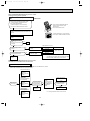
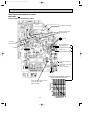
REFRIGERANT SYSTEM DIAGRAM
Unit:mm
MSH-18RV - E1
INDOOR UNIT
MUH-18RV - E1
MUH-18RV - E2
OUTDOOR UNIT
4- way valve
Refrigerant pipe [15.88
(with heat insulator)
Muffler
Indoor coil
thermistor
RT12
Distributor
Indoor
heat
exchanger
Strainer
Stop valve
(with service port)
Defrost
thermistor
RT61
Flared connection
Room temperature
thermistor
RT11
Outdoor
heat
exchanger
Accumulator
Compressor
Capillary tube
[3.0o[1.6o750
(2 pcs)
Flared connection
Strainer
Capillary tube
[3.0o[2.0o500
R.V. coil
Heating ON
Cooling OFF
Stop valve
Refrigerant pipe[6.35
(with heat insulator)
Check valve
Refrigerant flow in cooling
Refrigerant flow in heating
Unit:mm
MSH-24RV -
MUH-24RV - E1
OUTDOOR UNIT
E1
INDOOR UNIT
Refrigerant pipe [15.88
(with heat insulator)
4- way valve
Muffler
Indoor
heat
exchanger
Indoor coil
thermistor
RT12
Distributor
Room temperature
thermistor
RT11
Stop valve
(with service port)
Flared connection
Strainer
Outdoor
heat
exchanger
Accumulator
Defrost
Discharge pressure thermistor
RT61
regulator open
2.30MPa
Flared connection
(23.5 kgf/F)
Capillary tube
Check
[3.0X[1.6X350
Ambient
valve
temperature
Strainer
thermistor
RT63
R.V. coil
Stop valve
Capillary tube
Heating ON
[4.0X[2.4X200
Refrigerant pipe [9.52
Check
Cooling OFF
(with heat insulator)
valve
Refrigerant
flow
in
cooling
Capillary tube
Compressor
[3.0X[2.0X350
17
Refrigerant flow in heating
OB272-1.qxp
02.1.26 1:22 PM
Page 18
Unit:mm
MSH-30RV - E1
MUH-30RV - E1
4-way valve Strainer
Refrigerant pipe [15.88
(with heat insulator)
INDOOR UNIT
OUTDOOR UNIT
Muffler
Indoor coil
thermistor
RT12(main)
Indoor
heat
exchanger
Stop valve
(with service port)
Flared connection
Outdoor
heat
exchanger
Discharge
thermistor
RT62
Indoor coil
thermistor
RT13(sub)
Room temperature
thermistor
RT11
Defrost
thermistor
RT61
Accumulator
Compressor
Ambient
temperature
thermistor
RT63
Strainer
Check Capillary tube
valve [4.2✕[3.0✕50
LEV
Flared connection
Strainer
Stop valve
R.V. coil
heating ON
cooling OFF
Strainer
Capillary tube
[4.2✕[3.0✕50
Refrigerant pipe [9.52
(with heat insulator)
Refrigerant flow in cooling
Refrigerant flow in heating
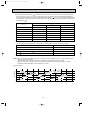
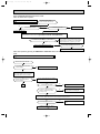
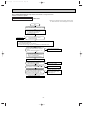
MAX. REFRIGERANT PIPING LENGTH
Refrigerant piping
Piping size O.D : mm
Max. length : m
Model
Gas
A
MSH-18RV MUH-18RV MUH-18RV -
Length of connecting pipe : m
Liquid
Indoor unit
Outdoor unit
Gas 0.43
Gas 0
Liquid 0.5
Liquid 0
E1
6.35
E1
E2
15
15.88
MSH-24RV MUH-24RV -
E1
MSH-30RV MUH-30RV -
E1
E1
9.52
30
E1
MAX. HEIGHT DIFFERENCE
Indoor
unit
wMax. Height
difference: 5m
(MSH-18/24RV)/
15m (MSH-30RV)
Refrigerant Piping
Max. Length
A
Outdoor unit
w Height difference should be within 5m (MSH-18/24RV) / 15m (MSH-30RV)
regardless of which unit, indoor or outdoor position is high.
18
OB272-1.qxp
02.1.26 1:22 PM
Page 19
ADDITIONAL REFRIGERANT CHARGE(R22 : g)
Refrigerant piping length (one way)
Outdoor unit precharged
Model
MSH-18RV MUH-18RV MUH-18RV -
7m
10m
15m
0
150
400
E1
E1
1,650
E2
Calculation : Xg=50g/m ✕ (Refrigerant piping length (m)–7)
Refrigerant piping length (one way)
Model
MSH-24RV MUH-24RV -
Outdoor unit precharged
E1
2,400
E1
7m
10m
15m
0
195
520
Calculation : Xg=65g/m ✕ (Refrigerant piping length (m)–7)
Model
MSH-30RV - E1
MUH-30RV - E1
Refrigerant piping length (one way)
Outdoor unit
precharged
7m
10m
15m
20m
25m
30m
2,300
0
195
520
845
1170
1495
Calculation : Xg=65g/mo(Refrigerant piping length(m)-7)
19
OB272-1.qxp
8
02.1.26 1:22 PM
Page 20
PERFORMANCE CURVES
MSH-18RV - E1 MUH-18RV - E1 MUH-18RV - E2
MSH-24RV - E1 MUH-24RV - E1
MSH-30RV - E1 MUH-30RV - E1
The standard data contained in these specifications apply only to the operation of the air conditioner under normal conditions,
since operating conditions vary according to the areas where these units are installed. The following information has been provided to clarify the operating characteristics of the air conditioner under the conditions indicated by the performance curve.
(1) GUARANTEED VOLTAGE
198 ~ 264V, 50Hz
(2) AIR FLOW
Air flow should be set at MAX.
(3) MAIN READINGS
(1) Indoor intake air wet-bulb temperature :
°CWB
(2) Indoor outlet air wet-bulb temperature :
°CWB
Cooling
(3) Outdoor intake air dry-bulb temperature :
°CDB
(4) Total input:
W
(5) Indoor intake air dry-bulb temperature :
°CDB
Heating
(6) Outdoor intake air wet-bulb temperature :
°CWB
(7) Total input :
W
}
}
Indoor air wet/dry-bulb temperature difference on the left side of the chart on this page and next page shows the difference between the indoor intake air wet/dry-bulb temperature and the indoor outlet air wet/dry-bulb temperature for your
reference at service.
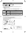
How to measure the indoor air wet-bulb/dry-bulb temperature difference
INDOOR UNIT
OUTDOOR UNIT
Wet-and dry-bulb
thermometers
Wet-and dry-bulb
thermometers
12.2
14.0 18.6
11.2
12.7 16.8
10.1
11.5 15.1
9.1
10.3 13.5
8.2
9.2 12.0
7.2
8.1 10.5
MSH-30RV - E1
3.
4.
5.
6.
7.
MSH-24RV - E1
2.
Attach at least 2 sets of wet-and dry-bulb thermometers to the indoor air intake as shown in the figure, and at least 2 sets
of wet-and dry-bulb thermometers to the indoor air outlet. The thermometers must be attached to the position where air
speed is high.
Attach at least 2 sets of wet-and dry-bulb thermometers to the outdoor air intake.
Cover the thermometers to prevent direct rays of the sun.
Check that the air filter is cleaned.
Open windows and doors of room.
Press the EMERGENCY OPERATION switch once(twice) to start the EMERGENCY COOL(HEAT) MODE.
When system stabilizes after more than 15 minutes, measure temperature and take an average temperature.
10 minutes later, measure temperature again and check that the temperature does not change.
MSH-18RV - E1
1.
20
02.1.26 1:22 PM
28.0
29.8 39.2
25.9
27.5 36.2
23.7
25.2 33.2
21.6
22.9 30.2
19.4
20.6 27.2
17.2
18.3 24.1
Page 21
MSH-30RV - E1
13.8 18.1
MSH-24RV - E1
16.1 21.1
12.9
MSH-18RV - E1
15.1
NOTE:The above curves are for the heating operation without any frost.
OUTDOOR LOW PRESSURE AND OUTDOOR UNIT CURRENT
COOL operation
1 Both indoor and outdoor unit are under the same temperature/humidity condition.
Dry-bulb temperature
Relative humidity(%)
20
50
25
60
30
70
2 Air flow should be set at MAX.
3 The unit of pressure has been changed to MPa on the international system of units(SI unit system).
f [Gauge])
The conversion factor is : 1(MPa [Gauge]) =10.2(kgf/f
(kgf/F[Gauge])(MPa[Gauge])
6
5
4
3
11
0.7
0.6
220V-240V
0.5
0.4
0.3
15
18 20
50
25
60
30 32
70(%)
10
220V-240V
9
8
7
6
15
35(:)
18 20
50
25
60
30 32
70(%)
Ambient temperature(˚C)
Ambient humidity(%)
Ambient temperature(˚C)
Ambient humidity(%)
MUH-24RV - E1
MUH-24RV - E1
(kgf/F[Gauge])(MPa[Gauge])
7
MUH-18RV - E1
MUH-18RV - E2
MUH-18RV - E1
MUH-18RV - E2
Outdoor unit current (A)
Outdoor low pressure
7
0.7
13
6
Outdoor unit current (A)
220V
Outdoor low pressure
OB272-1.qxp
0.6
5
0.5
4
0.4
3
0.3
2
0.2
220V-240V
Ambient temperature(˚C)
Ambient humidity(%)
12
240V
Ambient temperature(˚C)
Ambient humidity(%)
21
35(:)
02.1.26 1:22 PM
Page 22
(kgf/F[Gauge])(MPa[Gauge])
0.6
MUH-30RV - E1
MUH-30RV - E1
17
240V
Outdoor unit current(A)
Outdoor low pressure
6
0.5
5
220-240V
0.4
4
0.3
3
0.2
15
2
18 20
50
25
60
16
220V
15
14
13
12
11
10
15
30 32 35(:)
70
(%)
Ambient temperature(˚C)
Ambient humidity(%)
18 20
50
Condition indoor:Dry bulb temperature 20.0°C
Wet bulb temperature 14.5°C
Outdoor:Dry bulb temperature 7,15,20°C
Wet bulb temperature 6,12,14.5°C
MUH-18RV - E1
MUH-18RV - E2
MUH-24RV - E1
13
Outdoor unit current (A)
Outdoor unit current (A)
11
10
220V-240V
9
8
7
5
220V
12
240V
11
10
9
7
10
15
20 21
25(:)
Ambient temperature(˚C)
Ambient temperature(˚C)
MUH-30RV - E1
19
220V
18
240V
17
16
15
14
5
7
10
15
2021
25
60
30 32
70
Ambient temperature(˚C)
Ambient humidity(%)
HEAT operation
Outdoor unit current(A)
OB272-1.qxp
25(:)
Ambient temperature(˚C)
22
35(:)
(%)
OB272-1.qxp
02.1.26 1:22 PM
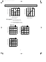
Page 23
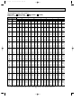
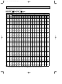
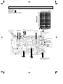
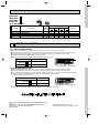
PERFORMANCE DATA COOL operation
MSH-18RV - E1 : MUH-18RV - E1 MUH-18RV - E2 (220V)
CAPACITY : 5.1(KW) SHF : 0.66
INPUT : 2030(W)
OUTDOOR DB(:)
21
25
27
INDOOR INDOOR
Q SHC SHF INPUT Q SHC SHF INPUT Q SHC SHF INPUT Q
DB(:) WB(:)
5.99 2.88 0.48 1624 5.74 2.75 0.48 1705 5.51 2.64 0.48 1786 5.30
18
21
6.25 2.25 0.36 1705 5.99 2.16 0.36 1807 5.81 2.09 0.36 1847 5.61
20
21
5.99 3.12 0.52 1624 5.74 2.98 0.52 1705 5.51 2.86 0.52 1786 5.30
18
22
6.25 2.50 0.40 1705 5.99 2.40 0.40 1807 5.81 2.33 0.40 1847 5.61
20
22
6.50 1.82 0.28 1766 6.27 1.76 0.28 1878 6.12 1.71 0.28 1929 5.87
22
22
5.99 3.36 0.56 1624 5.74 3.21 0.56 1705 5.51 3.08 0.56 1786 5.30
18
23
6.25 2.75 0.44 1705 5.99 2.64 0.44 1807 5.81 2.56 0.44 1847 5.61
20
23
6.50 2.08 0.32 1766 6.27 2.01 0.32 1878 6.12 1.96 0.32 1929 5.87
22
23
5.99 3.60 0.60 1624 5.74 3.44 0.60 1705 5.51 3.30 0.60 1786 5.30
18
24
6.25 3.00 0.48 1705 5.99 2.88 0.48 1807 5.81 2.79 0.48 1847 5.61
20
24
6.50 2.34 0.36 1766 6.27 2.26 0.36 1878 6.12 2.20 0.36 1929 5.87
22
24
6.83 1.64 0.24 1847 6.58 1.58 0.24 1949 6.43 1.54 0.24 2010 6.22
24
24
5.99 3.84 0.64 1624 5.74 3.67 0.64 1705 5.51 3.53 0.64 1786 5.30
18
25
6.25 3.25 0.52 1705 5.99 3.12 0.52 1807 5.81 3.02 0.52 1847 5.61
20
25
6.50 2.60 0.40 1766 6.27 2.51 0.40 1878 6.12 2.45 0.40 1929 5.87
22
25
6.83 1.91 0.28 1847 6.58 1.84 0.28 1949 6.43 1.80 0.28 2010 6.22
24
25
5.99 4.07 0.68 1624 5.74 3.90 0.68 1705 5.51 3.75 0.68 1786 5.30
18
26
6.25 3.50 0.56 1705 5.99 3.36 0.56 1807 5.81 3.26 0.56 1847 5.61
20
26
6.50 2.86 0.44 1766 6.27 2.76 0.44 1878 6.12 2.69 0.44 1929 5.87
22
26
6.83 2.19 0.32 1847 6.58 2.11 0.32 1949 6.43 2.06 0.32 2010 6.22
24
26
7.04 1.41 0.20 1949 6.83 1.37 0.20 2050 6.73 1.35 0.20 2111 6.53
26
26
5.99 4.31 0.72 1624 5.74 4.13 0.72 1705 5.51 3.97 0.72 1786 5.30
18
27
6.25 3.75 0.60 1705 5.99 3.60 0.60 1807 5.81 3.49 0.60 1847 5.61
20
27
6.50 3.12 0.48 1766 6.27 3.01 0.48 1878 6.12 2.94 0.48 1929 5.87
22
27
6.83 2.46 0.36 1847 6.58 2.37 0.36 1949 6.43 2.31 0.36 2010 6.22
24
27
7.04 1.69 0.24 1949 6.83 1.64 0.24 2050 6.73 1.62 0.24 2111 6.53
26
27
5.99 4.55 0.76 1624 5.74 4.36 0.76 1705 5.51 4.19 0.76 1786 5.30
18
28
6.25 4.00 0.64 1705 5.99 3.84 0.64 1807 5.81 3.72 0.64 1847 5.61
20
28
6.50 3.38 0.52 1766 6.27 3.26 0.52 1878 6.12 3.18 0.52 1929 5.87
22
28
6.83 2.73 0.40 1847 6.58 2.63 0.40 1949 6.43 2.57 0.40 2010 6.22
24
28
7.04 1.97 0.28 1949 6.83 1.91 0.28 2050 6.73 1.88 0.28 2111 6.53
26
28
5.99 4.79 0.80 1624 5.74 4.59 0.80 1705 5.51 4.41 0.80 1786 5.30
18
29
6.25 4.25 0.68 1705 5.99 4.07 0.68 1807 5.81 3.95 0.68 1847 5.61
20
29
6.50 3.64 0.56 1766 6.27 3.51 0.56 1878 6.12 3.43 0.56 1929 5.87
22
29
6.83 3.01 0.44 1847 6.58 2.89 0.44 1949 6.43 2.83 0.44 2010 6.22
24
29
7.04 2.25 0.32 1949 6.83 2.19 0.32 2050 6.73 2.15 0.32 2111 6.53
26
29
5.99 5.03 0.84 1624 5.74 4.82 0.84 1705 5.51 4.63 0.84 1786 5.30
18
30
6.25 4.50 0.72 1705 5.99 4.31 0.72 1807 5.81 4.19 0.72 1847 5.61
20
30
6.50 3.90 0.60 1766 6.27 3.76 0.60 1878 6.12 3.67 0.60 1929 5.87
22
30
6.83 3.28 0.48 1847 6.58 3.16 0.48 1949 6.43 3.08 0.48 2010 6.22
24
30
7.04 2.53 0.36 1949 6.83 2.46 0.36 2050 6.73 2.42 0.36 2111 6.53
26
30
5.99 5.27 0.88 1624 5.74 5.05 0.88 1705 5.51 4.85 0.88 1786 5.30
18
31
6.25 4.75 0.76 1705 5.99 4.55 0.76 1807 5.81 4.42 0.76 1847 5.61
20
31
6.50 4.16 0.64 1766 6.27 4.01 0.64 1878 6.12 3.92 0.64 1929 5.87
22
31
6.83 3.55 0.52 1847 6.58 3.42 0.52 1949 6.43 3.34 0.52 2010 6.22
24
31
7.04 2.82 0.40 1949 6.83 2.73 0.40 2050 6.73 2.69 0.40 2111 6.53
26
31
5.99 5.51 0.92 1624 5.74 5.28 0.92 1705 5.51 5.07 0.92 1786 5.30
18
32
6.25 5.00 0.80 1705 5.99 4.79 0.80 1807 5.81 4.65 0.80 1847 5.61
20
32
6.50 4.42 0.68 1766 6.27 4.27 0.68 1878 6.12 4.16 0.68 1929 5.87
22
32
6.83 3.83 0.56 1847 6.58 3.68 0.56 1949 6.43 3.60 0.56 2010 6.22
24
32
7.04 3.10 0.44 1949 6.83 3.01 0.44 2050 6.73 2.96 0.44 2111 6.53
26
32
NOTE
Q : Total capacity (kW)
SHF : Sensible heat factor
DB : Dry-bulb temperature
SHC : Sensible heat capacity (kW) INPUT : Total power input (W) WB : Wet-bulb temperature
23
SHC
2.55
2.02
2.76
2.24
1.64
2.97
2.47
1.88
3.18
2.69
2.11
1.49
3.39
2.92
2.35
1.74
3.61
3.14
2.58
1.99
1.31
3.82
3.37
2.82
2.24
1.57
4.03
3.59
3.05
2.49
1.83
4.24
3.81
3.28
2.74
2.09
4.46
4.04
3.52
2.99
2.35
4.67
4.26
3.75
3.24
2.61
4.88
4.49
3.99
3.48
2.87
30
SHF INPUT
0.48 1868
0.36 1929
0.52 1868
0.40 1929
0.28 2010
0.56 1868
0.44 1929
0.32 2010
0.60 1868
0.48 1929
0.36 2010
0.24 2111
0.64 1868
0.52 1929
0.40 2010
0.28 2111
0.68 1868
0.56 1929
0.44 2010
0.32 2111
0.20 2172
0.72 1868
0.60 1929
0.48 2010
0.36 2111
0.24 2172
0.76 1868
0.64 1929
0.52 2010
0.40 2111
0.28 2172
0.80 1868
0.68 1929
0.56 2010
0.44 2111
0.32 2172
0.84 1868
0.72 1929
0.60 2010
0.48 2111
0.36 2172
0.88 1868
0.76 1929
0.64 2010
0.52 2111
0.40 2172
0.92 1868
0.80 1929
0.68 2010
0.56 2111
0.44 2172
OB272-1.qxp
02.1.26 1:22 PM
Page 24
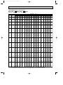
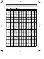
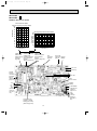
PERFORMANCE DATA COOL operation
MSH-18RV - E1 : MUH-18RV - E1 MUH-18RV - E2 (220V)
CAPACITY : 5.1(KW) SHF : 0.66
INDOOR INDOOR
DB(:) WB(:)
18
21
20
21
18
22
20
22
22
22
18
23
20
23
22
23
18
24
20
24
22
24
24
24
18
25
20
25
22
25
24
25
18
26
20
26
22
26
24
26
26
26
18
27
20
27
22
27
24
27
26
27
18
28
20
28
22
28
24
28
26
28
18
29
20
29
22
29
24
29
26
29
18
30
20
30
22
30
24
30
26
30
18
31
20
31
22
31
24
31
26
31
18
32
20
32
22
32
24
32
26
32
NOTE
Q
5.00
5.25
5.00
5.25
5.56
5.00
5.25
5.56
5.00
5.25
5.56
5.87
5.00
5.25
5.56
5.87
5.00
5.25
5.56
5.87
6.17
5.00
5.25
5.56
5.87
6.17
5.00
5.25
5.56
5.87
6.17
5.00
5.25
5.56
5.87
6.17
5.00
5.25
5.56
5.87
6.17
5.00
5.25
5.56
5.87
6.17
5.00
5.25
5.56
5.87
6.17
INPUT : 2030(W)
OUTDOOR DB(:)
35
40
43
46
SHC SHF INPUT Q SHC SHF INPUT Q SHC SHF INPUT Q SHC SHF INPUT
2.40 0.48 1989 4.59 2.20 0.48 2111 4.41 2.12 0.48 2152 4.23 2.03 0.48 2192
1.89 0.36 2071 4.90 1.76 0.36 2172 4.72 1.70 0.36 2233 4.54 1.63 0.36 2294
2.60 0.52 1989 4.59 2.39 0.52 2111 4.41 2.29 0.52 2152 4.23 2.20 0.52 2192
2.10 0.40 2071 4.90 1.96 0.40 2172 4.72 1.89 0.40 2233 4.54 1.82 0.40 2294
1.56 0.28 2152 5.20 1.46 0.28 2274 5.02 1.41 0.28 2314 4.85 1.36 0.28 2355
2.80 0.56 1989 4.59 2.57 0.56 2111 4.41 2.47 0.56 2152 4.23 2.37 0.56 2192
2.31 0.44 2071 4.90 2.15 0.44 2172 4.72 2.08 0.44 2233 4.54 2.00 0.44 2294
1.78 0.32 2152 5.20 1.66 0.32 2274 5.02 1.61 0.32 2314 4.85 1.55 0.32 2355
3.00 0.60 1989 4.59 2.75 0.60 2111 4.41 2.65 0.60 2152 4.23 2.54 0.60 2192
2.52 0.48 2071 4.90 2.35 0.48 2172 4.72 2.26 0.48 2233 4.54 2.18 0.48 2294
2.00 0.36 2152 5.20 1.87 0.36 2274 5.02 1.81 0.36 2314 4.85 1.74 0.36 2355
1.41 0.24 2233 5.51 1.32 0.24 2335 5.36 1.29 0.24 2385 5.20 1.25 0.24 2436
3.20 0.64 1989 4.59 2.94 0.64 2111 4.41 2.82 0.64 2152 4.23 2.71 0.64 2192
2.73 0.52 2071 4.90 2.55 0.52 2172 4.72 2.45 0.52 2233 4.54 2.36 0.52 2294
2.22 0.40 2152 5.20 2.08 0.40 2274 5.02 2.01 0.40 2314 4.85 1.94 0.40 2355
1.64 0.28 2233 5.51 1.54 0.28 2335 5.36 1.50 0.28 2385 5.20 1.46 0.28 2436
3.40 0.68 1989 4.59 3.12 0.68 2111 4.41 3.00 0.68 2152 4.23 2.88 0.68 2192
2.94 0.56 2071 4.90 2.74 0.56 2172 4.72 2.64 0.56 2233 4.54 2.54 0.56 2294
2.45 0.44 2152 5.20 2.29 0.44 2274 5.02 2.21 0.44 2314 4.85 2.13 0.44 2355
1.88 0.32 2233 5.51 1.76 0.32 2335 5.36 1.71 0.32 2385 5.20 1.66 0.32 2436
1.23 0.20 2314 5.81 1.16 0.20 2416 5.64 1.13 0.20 2466 5.46 1.09 0.20 2517
3.60 0.72 1989 4.59 3.30 0.72 2111 4.41 3.18 0.72 2152 4.23 3.05 0.72 2192
3.15 0.60 2071 4.90 2.94 0.60 2172 4.72 2.83 0.60 2233 4.54 2.72 0.60 2294
2.67 0.48 2152 5.20 2.50 0.48 2274 5.02 2.41 0.48 2314 4.85 2.33 0.48 2355
2.11 0.36 2233 5.51 1.98 0.36 2335 5.36 1.93 0.36 2385 5.20 1.87 0.36 2436
1.48 0.24 2314 5.81 1.40 0.24 2416 5.64 1.35 0.24 2466 5.46 1.31 0.24 2517
3.80 0.76 1989 4.59 3.49 0.76 2111 4.41 3.35 0.76 2152 4.23 3.22 0.76 2192
3.36 0.64 2071 4.90 3.13 0.64 2172 4.72 3.02 0.64 2233 4.54 2.90 0.64 2294
2.89 0.52 2152 5.20 2.71 0.52 2274 5.02 2.61 0.52 2314 4.85 2.52 0.52 2355
2.35 0.40 2233 5.51 2.20 0.40 2335 5.36 2.14 0.40 2385 5.20 2.08 0.40 2436
1.73 0.28 2314 5.81 1.63 0.28 2416 5.64 1.58 0.28 2466 5.46 1.53 0.28 2517
4.00 0.80 1989 4.59 3.67 0.80 2111 4.41 3.53 0.80 2152 4.23 3.39 0.80 2192
3.57 0.68 2071 4.90 3.33 0.68 2172 4.72 3.21 0.68 2233 4.54 3.09 0.68 2294
3.11 0.56 2152 5.20 2.91 0.56 2274 5.02 2.81 0.56 2314 4.85 2.71 0.56 2355
2.58 0.44 2233 5.51 2.42 0.44 2335 5.36 2.36 0.44 2385 5.20 2.29 0.44 2436
1.97 0.32 2314 5.81 1.86 0.32 2416 5.64 1.80 0.32 2466 5.46 1.75 0.32 2517
4.20 0.84 1989 4.59 3.86 0.84 2111 4.41 3.71 0.84 2152 4.23 3.56 0.84 2192
3.78 0.72 2071 4.90 3.53 0.72 2172 4.72 3.40 0.72 2233 4.54 3.27 0.72 2294
3.34 0.60 2152 5.20 3.12 0.60 2274 5.02 3.01 0.60 2314 4.85 2.91 0.60 2355
2.82 0.48 2233 5.51 2.64 0.48 2335 5.36 2.57 0.48 2385 5.20 2.50 0.48 2436
2.22 0.36 2314 5.81 2.09 0.36 2416 5.64 2.03 0.36 2466 5.46 1.96 0.36 2517
4.40 0.88 1989 4.59 4.04 0.88 2111 4.41 3.88 0.88 2152 4.23 3.73 0.88 2192
3.99 0.76 2071 4.90 3.72 0.76 2172 4.72 3.59 0.76 2233 4.54 3.45 0.76 2294
3.56 0.64 2152 5.20 3.33 0.64 2274 5.02 3.22 0.64 2314 4.85 3.10 0.64 2355
3.05 0.52 2233 5.51 2.86 0.52 2335 5.36 2.78 0.52 2385 5.20 2.71 0.52 2436
2.47 0.40 2314 5.81 2.33 0.40 2416 5.64 2.25 0.40 2466 5.46 2.18 0.40 2517
4.60 0.92 1989 4.59 4.22 0.92 2111 4.41 4.06 0.92 2152 4.23 3.89 0.92 2192
4.20 0.80 2071 4.90 3.92 0.80 2172 4.72 3.77 0.80 2233 4.54 3.63 0.80 2294
3.78 0.68 2152 5.20 3.54 0.68 2274 5.02 3.42 0.68 2314 4.85 3.29 0.68 2355
3.28 0.56 2233 5.51 3.08 0.56 2335 5.36 3.00 0.56 2385 5.20 2.91 0.56 2436
2.72 0.44 2314 5.81 2.56 0.44 2416 5.64 2.48 0.44 2466 5.46 2.40 0.44 2517
Q : Total capacity (kW)
SHC : Sensible heat capacity (kW)
SHF : Sensible heat factor
INPUT : Total power input (W)
24
DB : Dry-bulb temperature
WB : Wet-bulb temperature
OB272-1.qxp
02.1.26 1:22 PM
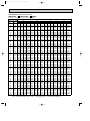
Page 25
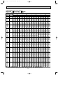
PERFORMANCE DATA COOL operation
MSH-18RV - E1 : MUH-18RV - E1 MUH-18RV - E2 (240V)
CAPACITY : 5.1(KW) SHF : 0.66
INPUT : 2120(W)
OUTDOOR DB(:)
21
25
27
INDOOR INDOOR
Q
SHC
SHF
INPUT
Q
SHC
SHF
INPUT
Q
SHC
SHF INPUT Q
DB(:) WB(:)
5.99 2.88 0.48 1696 5.74 2.75 0.48 1781 5.51 2.64 0.48 1866 5.30
18
21
6.25 2.25 0.36 1781 5.99 2.16 0.36 1887 5.81 2.09 0.36 1929 5.61
20
21
5.99 3.12 0.52 1696 5.74 2.98 0.52 1781 5.51 2.86 0.52 1866 5.30
18
22
6.25 2.50 0.40 1781 5.99 2.40 0.40 1887 5.81 2.33 0.40 1929 5.61
20
22
6.50 1.82 0.28 1844 6.27 1.76 0.28 1961 6.12 1.71 0.28 2014 5.87
22
22
5.99 3.36 0.56 1696 5.74 3.21 0.56 1781 5.51 3.08 0.56 1866 5.30
18
23
6.25 2.75 0.44 1781 5.99 2.64 0.44 1887 5.81 2.56 0.44 1929 5.61
20
23
6.50 2.08 0.32 1844 6.27 2.01 0.32 1961 6.12 1.96 0.32 2014 5.87
22
23
5.99 3.60 0.60 1696 5.74 3.44 0.60 1781 5.51 3.30 0.60 1866 5.30
18
24
6.25 3.00 0.48 1781 5.99 2.88 0.48 1887 5.81 2.79 0.48 1929 5.61
20
24
6.50 2.34 0.36 1844 6.27 2.26 0.36 1961 6.12 2.20 0.36 2014 5.87
22
24
6.83 1.64 0.24 1929 6.58 1.58 0.24 2035 6.43 1.54 0.24 2099 6.22
24
24
5.99 3.84 0.64 1696 5.74 3.67 0.64 1781 5.51 3.53 0.64 1866 5.30
18
25
6.25 3.25 0.52 1781 5.99 3.12 0.52 1887 5.81 3.02 0.52 1929 5.61
20
25
6.50 2.60 0.40 1844 6.27 2.51 0.40 1961 6.12 2.45 0.40 2014 5.87
22
25
6.83 1.91 0.28 1929 6.58 1.84 0.28 2035 6.43 1.80 0.28 2099 6.22
24
25
5.99 4.07 0.68 1696 5.74 3.90 0.68 1781 5.51 3.75 0.68 1866 5.30
18
26
6.25 3.50 0.56 1781 5.99 3.36 0.56 1887 5.81 3.26 0.56 1929 5.61
20
26
6.50 2.86 0.44 1844 6.27 2.76 0.44 1961 6.12 2.69 0.44 2014 5.87
22
26
6.83 2.19 0.32 1929 6.58 2.11 0.32 2035 6.43 2.06 0.32 2099 6.22
24
26
7.04 1.41 0.20 2035 6.83 1.37 0.20 2141 6.73 1.35 0.20 2205 6.53
26
26
5.99 4.31 0.72 1696 5.74 4.13 0.72 1781 5.51 3.97 0.72 1866 5.30
18
27
6.25 3.75 0.60 1781 5.99 3.60 0.60 1887 5.81 3.49 0.60 1929 5.61
20
27
6.50 3.12 0.48 1844 6.27 3.01 0.48 1961 6.12 2.94 0.48 2014 5.87
22
27
6.83 2.46 0.36 1929 6.58 2.37 0.36 2035 6.43 2.31 0.36 2099 6.22
24
27
7.04 1.69 0.24 2035 6.83 1.64 0.24 2141 6.73 1.62 0.24 2205 6.53
26
27
5.99 4.55 0.76 1696 5.74 4.36 0.76 1781 5.51 4.19 0.76 1866 5.30
18
28
6.25 4.00 0.64 1781 5.99 3.84 0.64 1887 5.81 3.72 0.64 1929 5.61
20
28
6.50 3.38 0.52 1844 6.27 3.26 0.52 1961 6.12 3.18 0.52 2014 5.87
22
28
6.83 2.73 0.40 1929 6.58 2.63 0.40 2035 6.43 2.57 0.40 2099 6.22
24
28
7.04 1.97 0.28 2035 6.83 1.91 0.28 2141 6.73 1.88 0.28 2205 6.53
26
28
5.99 4.79 0.80 1696 5.74 4.59 0.80 1781 5.51 4.41 0.80 1866 5.30
18
29
6.25 4.25 0.68 1781 5.99 4.07 0.68 1887 5.81 3.95 0.68 1929 5.61
20
29
6.50 3.64 0.56 1844 6.27 3.51 0.56 1961 6.12 3.43 0.56 2014 5.87
22
29
6.83 3.01 0.44 1929 6.58 2.89 0.44 2035 6.43 2.83 0.44 2099 6.22
24
29
7.04 2.25 0.32 2035 6.83 2.19 0.32 2141 6.73 2.15 0.32 2205 6.53
26
29
5.99 5.03 0.84 1696 5.74 4.82 0.84 1781 5.51 4.63 0.84 1866 5.30
18
30
6.25 4.50 0.72 1781 5.99 4.31 0.72 1887 5.81 4.19 0.72 1929 5.61
20
30
6.50 3.90 0.60 1844 6.27 3.76 0.60 1961 6.12 3.67 0.60 2014 5.87
22
30
6.83 3.28 0.48 1929 6.58 3.16 0.48 2035 6.43 3.08 0.48 2099 6.22
24
30
7.04 2.53 0.36 2035 6.83 2.46 0.36 2141 6.73 2.42 0.36 2205 6.53
26
30
5.99 5.27 0.88 1696 5.74 5.05 0.88 1781 5.51 4.85 0.88 1866 5.30
18
31
6.25 4.75 0.76 1781 5.99 4.55 0.76 1887 5.81 4.42 0.76 1929 5.61
20
31
6.50 4.16 0.64 1844 6.27 4.01 0.64 1961 6.12 3.92 0.64 2014 5.87
22
31
6.83 3.55 0.52 1929 6.58 3.42 0.52 2035 6.43 3.34 0.52 2099 6.22
24
31
7.04 2.82 0.40 2035 6.83 2.73 0.40 2141 6.73 2.69 0.40 2205 6.53
26
31
5.99 5.51 0.92 1696 5.74 5.28 0.92 1781 5.51 5.07 0.92 1866 5.30
18
32
6.25 5.00 0.80 1781 5.99 4.79 0.80 1887 5.81 4.65 0.80 1929 5.61
20
32
6.50 4.42 0.68 1844 6.27 4.27 0.68 1961 6.12 4.16 0.68 2014 5.87
22
32
6.83 3.83 0.56 1929 6.58 3.68 0.56 2035 6.43 3.60 0.56 2099 6.22
24
32
7.04 3.10 0.44 2035 6.83 3.01 0.44 2141 6.73 2.96 0.44 2205 6.53
26
32
NOTE
Q : Total capacity (kW)
SHF : Sensible heat factor
DB : Dry-bulb temperature
SHC : Sensible heat capacity (kW) INPUT : Total power input (W) WB : Wet-bulb temperature
25
SHC
2.55
2.02
2.76
2.24
1.64
2.97
2.47
1.88
3.18
2.69
2.11
1.49
3.39
2.92
2.35
1.74
3.61
3.14
2.58
1.99
1.31
3.82
3.37
2.82
2.24
1.57
4.03
3.59
3.05
2.49
1.83
4.24
3.81
3.28
2.74
2.09
4.46
4.04
3.52
2.99
2.35
4.67
4.26
3.75
3.24
2.61
4.88
4.49
3.99
3.48
2.87
30
SHF INPUT
0.48 1950
0.36 2014
0.52 1950
0.40 2014
0.28 2099
0.56 1950
0.44 2014
0.32 2099
0.60 1950
0.48 2014
0.36 2099
0.24 2205
0.64 1950
0.52 2014
0.40 2099
0.28 2205
0.68 1950
0.56 2014
0.44 2099
0.32 2205
0.20 2268
0.72 1950
0.60 2014
0.48 2099
0.36 2205
0.24 2268
0.76 1950
0.64 2014
0.52 2099
0.40 2205
0.28 2268
0.80 1950
0.68 2014
0.56 2099
0.44 2205
0.32 2268
0.84 1950
0.72 2014
0.60 2099
0.48 2205
0.36 2268
0.88 1950
0.76 2014
0.64 2099
0.52 2205
0.40 2268
0.92 1950
0.80 2014
0.68 2099
0.56 2205
0.44 2268
OB272-1.qxp
02.1.26 1:22 PM
Page 26
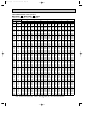
PERFORMANCE DATA COOL operation
MSH-18RV - E1 : MUH-18RV - E1 MUH-18RV - E2 (240V)
CAPACITY : 5.1(KW) SHF : 0.66
INPUT : 2120(W)
OUTDOOR DB(:)
35
40
43
INDOOR INDOOR
Q SHC SHF INPUT Q SHC SHF INPUT Q SHC SHF INPUT Q
DB(:) WB(:)
5.00 2.40 0.48 2078 4.59 2.20 0.48 2205 4.41 2.12 0.48 2247 4.23
18
21
5.25 1.89 0.36 2162 4.90 1.76 0.36 2268 4.72 1.70 0.36 2332 4.54
20
21
5.00 2.60 0.52 2078 4.59 2.39 0.52 2205 4.41 2.29 0.52 2247 4.23
18
22
5.25 2.10 0.40 2162 4.90 1.96 0.40 2268 4.72 1.89 0.40 2332 4.54
20
22
5.56 1.56 0.28 2247 5.20 1.46 0.28 2374 5.02 1.41 0.28 2417 4.85
22
22
5.00 2.80 0.56 2078 4.59 2.57 0.56 2205 4.41 2.47 0.56 2247 4.23
18
23
5.25 2.31 0.44 2162 4.90 2.15 0.44 2268 4.72 2.08 0.44 2332 4.54
20
23
5.56 1.78 0.32 2247 5.20 1.66 0.32 2374 5.02 1.61 0.32 2417 4.85
22
23
5.00 3.00 0.60 2078 4.59 2.75 0.60 2205 4.41 2.65 0.60 2247 4.23
18
24
5.25 2.52 0.48 2162 4.90 2.35 0.48 2268 4.72 2.26 0.48 2332 4.54
20
24
5.56 2.00 0.36 2247 5.20 1.87 0.36 2374 5.02 1.81 0.36 2417 4.85
22
24
5.87 1.41 0.24 2332 5.51 1.32 0.24 2438 5.36 1.29 0.24 2491 5.20
24
24
5.00 3.20 0.64 2078 4.59 2.94 0.64 2205 4.41 2.82 0.64 2247 4.23
18
25
5.25 2.73 0.52 2162 4.90 2.55 0.52 2268 4.72 2.45 0.52 2332 4.54
20
25
5.56 2.22 0.40 2247 5.20 2.08 0.40 2374 5.02 2.01 0.40 2417 4.85
22
25
5.87 1.64 0.28 2332 5.51 1.54 0.28 2438 5.36 1.50 0.28 2491 5.20
24
25
5.00 3.40 0.68 2078 4.59 3.12 0.68 2205 4.41 3.00 0.68 2247 4.23
18
26
5.25 2.94 0.56 2162 4.90 2.74 0.56 2268 4.72 2.64 0.56 2332 4.54
20
26
5.56 2.45 0.44 2247 5.20 2.29 0.44 2374 5.02 2.21 0.44 2417 4.85
22
26
5.87 1.88 0.32 2332 5.51 1.76 0.32 2438 5.36 1.71 0.32 2491 5.20
24
26
6.17 1.23 0.20 2417 5.81 1.16 0.20 2523 5.64 1.13 0.20 2576 5.46
26
26
5.00 3.60 0.72 2078 4.59 3.30 0.72 2205 4.41 3.18 0.72 2247 4.23
18
27
5.25 3.15 0.60 2162 4.90 2.94 0.60 2268 4.72 2.83 0.60 2332 4.54
20
27
5.56 2.67 0.48 2247 5.20 2.50 0.48 2374 5.02 2.41 0.48 2417 4.85
22
27
5.87 2.11 0.36 2332 5.51 1.98 0.36 2438 5.36 1.93 0.36 2491 5.20
24
27
6.17 1.48 0.24 2417 5.81 1.40 0.24 2523 5.64 1.35 0.24 2576 5.46
26
27
5.00 3.80 0.76 2078 4.59 3.49 0.76 2205 4.41 3.35 0.76 2247 4.23
18
28
5.25 3.36 0.64 2162 4.90 3.13 0.64 2268 4.72 3.02 0.64 2332 4.54
20
28
5.56 2.89 0.52 2247 5.20 2.71 0.52 2374 5.02 2.61 0.52 2417 4.85
22
28
5.87 2.35 0.40 2332 5.51 2.20 0.40 2438 5.36 2.14 0.40 2491 5.20
24
28
6.17 1.73 0.28 2417 5.81 1.63 0.28 2523 5.64 1.58 0.28 2576 5.46
26
28
5.00 4.00 0.80 2078 4.59 3.67 0.80 2205 4.41 3.53 0.80 2247 4.23
18
29
5.25 3.57 0.68 2162 4.90 3.33 0.68 2268 4.72 3.21 0.68 2332 4.54
20
29
5.56 3.11 0.56 2247 5.20 2.91 0.56 2374 5.02 2.81 0.56 2417 4.85
22
29
5.87 2.58 0.44 2332 5.51 2.42 0.44 2438 5.36 2.36 0.44 2491 5.20
24
29
6.17 1.97 0.32 2417 5.81 1.86 0.32 2523 5.64 1.80 0.32 2576 5.46
26
29
5.00 4.20 0.84 2078 4.59 3.86 0.84 2205 4.41 3.71 0.84 2247 4.23
18
30
5.25 3.78 0.72 2162 4.90 3.53 0.72 2268 4.72 3.40 0.72 2332 4.54
20
30
5.56 3.34 0.60 2247 5.20 3.12 0.60 2374 5.02 3.01 0.60 2417 4.85
22
30
5.87 2.82 0.48 2332 5.51 2.64 0.48 2438 5.36 2.57 0.48 2491 5.20
24
30
6.17 2.22 0.36 2417 5.81 2.09 0.36 2523 5.64 2.03 0.36 2576 5.46
26
30
5.00 4.40 0.88 2078 4.59 4.04 0.88 2205 4.41 3.88 0.88 2247 4.23
18
31
5.25 3.99 0.76 2162 4.90 3.72 0.76 2268 4.72 3.59 0.76 2332 4.54
20
31
5.56 3.56 0.64 2247 5.20 3.33 0.64 2374 5.02 3.22 0.64 2417 4.85
22
31
5.87 3.05 0.52 2332 5.51 2.86 0.52 2438 5.36 2.78 0.52 2491 5.20
24
31
6.17 2.47 0.40 2417 5.81 2.33 0.40 2523 5.64 2.25 0.40 2576 5.46
26
31
5.00 4.60 0.92 2078 4.59 4.22 0.92 2205 4.41 4.06 0.92 2247 4.23
18
32
5.25 4.20 0.80 2162 4.90 3.92 0.80 2268 4.72 3.77 0.80 2332 4.54
20
32
5.56 3.78 0.68 2247 5.20 3.54 0.68 2374 5.02 3.42 0.68 2417 4.85
22
32
5.87 3.28 0.56 2332 5.51 3.08 0.56 2438 5.36 3.00 0.56 2491 5.20
24
32
6.17 2.72 0.44 2417 5.81 2.56 0.44 2523 5.64 2.48 0.44 2576 5.46
26
32
NOTE
Q : Total capacity (kW)
SHF : Sensible heat factor
DB : Dry-bulb temperature
SHC : Sensible heat capacity (kW) INPUT : Total power input (W) WB : Wet-bulb temperature
26
SHC
2.03
1.63
2.20
1.82
1.36
2.37
2.00
1.55
2.54
2.18
1.74
1.25
2.71
2.36
1.94
1.46
2.88
2.54
2.13
1.66
1.09
3.05
2.72
2.33
1.87
1.31
3.22
2.90
2.52
2.08
1.53
3.39
3.09
2.71
2.29
1.75
3.56
3.27
2.91
2.50
1.96
3.73
3.45
3.10
2.71
2.18
3.89
3.63
3.29
2.91
2.40
46
SHF INPUT
0.48 2290
0.36 2396
0.52 2290
0.40 2396
0.28 2459
0.56 2290
0.44 2396
0.32 2459
0.60 2290
0.48 2396
0.36 2459
0.24 2544
0.64 2290
0.52 2396
0.40 2459
0.28 2544
0.68 2290
0.56 2396
0.44 2459
0.32 2544
0.20 2629
0.72 2290
0.60 2396
0.48 2459
0.36 2544
0.24 2629
0.76 2290
0.64 2396
0.52 2459
0.40 2544
0.28 2629
0.80 2290
0.68 2396
0.56 2459
0.44 2544
0.32 2629
0.84 2290
0.72 2396
0.60 2459
0.48 2544
0.36 2629
0.88 2290
0.76 2396
0.64 2459
0.52 2544
0.40 2629
0.92 2290
0.80 2396
0.68 2459
0.56 2544
0.44 2629
OB272-1.qxp
02.1.26 1:22 PM
Page 27
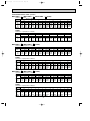
PERFORMANCE DATA COOL operation
MSH-24RV - E1 : MUH-24RV - E1 (220V)
CAPACITY : 6.0(KW) SHF : 0.65
INPUT : 2720(W)
OUTDOOR DB(:)
21
25
27
INDOOR INDOOR
Q SHC SHF INPUT Q SHC SHF INPUT Q SHC SHF INPUT Q
DB(:) WB(:)
7.05 3.31 0.47 2176 6.75 3.17 0.47 2285 6.48 3.05 0.47 2394 6.24
18
21
7.35 2.57 0.35 2285 7.05 2.47 0.35 2421 6.84 2.39 0.35 2475 6.60
20
21
7.05 3.60 0.51 2176 6.75 3.44 0.51 2285 6.48 3.30 0.51 2394 6.24
18
22
7.35 2.87 0.39 2285 7.05 2.75 0.39 2421 6.84 2.67 0.39 2475 6.60
20
22
7.65 2.07 0.27 2366 7.38 1.99 0.27 2516 7.20 1.94 0.27 2584 6.90
22
22
7.05 3.88 0.55 2176 6.75 3.71 0.55 2285 6.48 3.56 0.55 2394 6.24
18
23
7.35 3.16 0.43 2285 7.05 3.03 0.43 2421 6.84 2.94 0.43 2475 6.60
20
23
7.65 2.37 0.31 2366 7.38 2.29 0.31 2516 7.20 2.23 0.31 2584 6.90
22
23
7.05 4.16 0.59 2176 6.75 3.98 0.59 2285 6.48 3.82 0.59 2394 6.24
18
24
7.35 3.45 0.47 2285 7.05 3.31 0.47 2421 6.84 3.21 0.47 2475 6.60
20
24
7.65 2.68 0.35 2366 7.38 2.58 0.35 2516 7.20 2.52 0.35 2584 6.90
22
24
8.04 1.85 0.23 2475 7.74 1.78 0.23 2611 7.56 1.74 0.23 2693 7.32
24
24
7.05 4.44 0.63 2176 6.75 4.25 0.63 2285 6.48 4.08 0.63 2394 6.24
18
25
7.35 3.75 0.51 2285 7.05 3.60 0.51 2421 6.84 3.49 0.51 2475 6.60
20
25
7.65 2.98 0.39 2366 7.38 2.88 0.39 2516 7.20 2.81 0.39 2584 6.90
22
25
8.04 2.17 0.27 2475 7.74 2.09 0.27 2611 7.56 2.04 0.27 2693 7.32
24
25
7.05 4.72 0.67 2176 6.75 4.52 0.67 2285 6.48 4.34 0.67 2394 6.24
18
26
7.35 4.04 0.55 2285 7.05 3.88 0.55 2421 6.84 3.76 0.55 2475 6.60
20
26
7.65 3.29 0.43 2366 7.38 3.17 0.43 2516 7.20 3.10 0.43 2584 6.90
22
26
8.04 2.49 0.31 2475 7.74 2.40 0.31 2611 7.56 2.34 0.31 2693 7.32
24
26
8.28 1.57 0.19 2611 8.04 1.53 0.19 2747 7.92 1.50 0.19 2829 7.68
26
26
7.05 5.01 0.71 2176 6.75 4.79 0.71 2285 6.48 4.60 0.71 2394 6.24
18
27
7.35 4.34 0.59 2285 7.05 4.16 0.59 2421 6.84 4.04 0.59 2475 6.60
20
27
7.65 3.60 0.47 2366 7.38 3.47 0.47 2516 7.20 3.38 0.47 2584 6.90
22
27
8.04 2.81 0.35 2475 7.74 2.71 0.35 2611 7.56 2.65 0.35 2693 7.32
24
27
8.28 1.90 0.23 2611 8.04 1.85 0.23 2747 7.92 1.82 0.23 2829 7.68
26
27
7.05 5.29 0.75 2176 6.75 5.06 0.75 2285 6.48 4.86 0.75 2394 6.24
18
28
7.35 4.63 0.63 2285 7.05 4.44 0.63 2421 6.84 4.31 0.63 2475 6.60
20
28
7.65 3.90 0.51 2366 7.38 3.76 0.51 2516 7.20 3.67 0.51 2584 6.90
22
28
8.04 3.14 0.39 2475 7.74 3.02 0.39 2611 7.56 2.95 0.39 2693 7.32
24
28
8.28 2.24 0.27 2611 8.04 2.17 0.27 2747 7.92 2.14 0.27 2829 7.68
26
28
7.05 5.57 0.79 2176 6.75 5.33 0.79 2285 6.48 5.12 0.79 2394 6.24
18
29
7.35 4.92 0.67 2285 7.05 4.72 0.67 2421 6.84 4.58 0.67 2475 6.60
20
29
7.65 4.21 0.55 2366 7.38 4.06 0.55 2516 7.20 3.96 0.55 2584 6.90
22
29
8.04 3.46 0.43 2475 7.74 3.33 0.43 2611 7.56 3.25 0.43 2693 7.32
24
29
8.28 2.57 0.31 2611 8.04 2.46 0.31 2747 7.92 2.46 0.31 2829 7.68
26
29
7.05 5.85 0.83 2176 6.75 5.60 0.83 2285 6.48 5.38 0.83 2394 6.24
18
30
7.35 5.22 0.71 2285 7.05 5.01 0.71 2421 6.84 4.86 0.71 2475 6.60
20
30
7.65 4.51 0.59 2366 7.38 4.35 0.59 2516 7.20 4.25 0.59 2584 6.90
22
30
8.04 3.78 0.47 2475 7.74 3.64 0.47 2611 7.56 3.55 0.47 2693 7.32
24
30
8.28 2.90 0.35 2611 8.04 2.81 0.35 2747 7.92 2.77 0.35 2829 7.68
26
30
7.05 6.13 0.87 2176 6.75 5.87 0.87 2285 6.48 5.64 0.87 2394 6.24
18
31
7.35 5.51 0.75 2285 7.05 5.29 0.75 2421 6.84 5.13 0.75 2475 6.60
20
31
7.65 4.82 0.63 2366 7.38 4.65 0.63 2516 7.20 4.54 0.63 2584 6.90
22
31
8.04 4.10 0.51 2475 7.74 3.95 0.51 2611 7.56 3.86 0.51 2693 7.32
24
31
8.28 3.23 0.39 2611 8.04 3.14 0.39 2747 7.92 3.09 0.39 2829 7.68
26
31
7.05 6.42 0.91 2176 6.75 6.14 0.91 2285 6.48 5.90 0.91 2394 6.24
18
32
7.35 5.81 0.79 2285 7.05 5.57 0.79 2421 6.84 5.40 0.79 2475 6.60
20
32
7.65 5.13 0.67 2366 7.38 4.94 0.67 2516 7.20 4.82 0.67 2584 6.90
22
32
8.04 4.42 0.55 2475 7.74 4.26 0.55 2611 7.56 4.16 0.55 2693 7.32
24
32
8.28 3.56 0.43 2611 8.04 3.46 0.43 2747 7.92 3.41 0.43 2829 7.68
26
32
NOTE
Q : Total capacity (kW)
SHF : Sensible heat factor
DB : Dry-bulb temperature
SHC : Sensible heat capacity (kW) INPUT : Total power input (W) WB : Wet-bulb temperature
27
SHC
2.93
2.31
3.18
2.57
1.86
3.43
2.84
2.14
3.68
3.10
2.42
1.68
3.93
3.37
2.69
1.98
4.18
3.63
2.97
2.27
1.46
4.43
3.89
3.24
2.56
1.77
4.68
4.16
3.52
2.85
2.07
4.93
4.42
3.80
3.15
2.38
5.18
4.69
4.07
3.44
2.69
5.43
4.95
4.35
3.73
3.00
5.68
5.21
4.62
4.03
3.30
30
SHF INPUT
0.47 2502
0.35 2584
0.51 2502
0.39 2584
0.27 2693
0.55 2502
0.43 2584
0.31 2693
0.59 2502
0.47 2584
0.35 2693
0.23 2829
0.63 2502
0.51 2584
0.39 2693
0.27 2829
0.67 2502
0.55 2584
0.43 2693
0.31 2829
0.19 2910
0.71 2502
0.59 2584
0.47 2693
0.35 2829
0.23 2910
0.75 2502
0.63 2584
0.51 2693
0.39 2829
0.27 2910
0.79 2502
0.67 2584
0.55 2693
0.43 2829
0.31 2910
0.83 2502
.071 2584
0.59 2693
0.47 2829
0.35 2910
0.87 2502
0.75 2584
0.63 2693
0.51 2829
0.39 2910
0.91 2502
0.79 2584
0.67 2693
0.55 2829
0.43 2910
OB272-1.qxp
02.1.26 1:22 PM
Page 28
PERFORMANCE DATA COOL operation
MSH-24RV - E1 : MUH-24RV - E1 (220V)
CAPACITY : 6.0(KW) SHF : 0.65
INPUT : 2720(W)
OUTDOOR DB(:)
35
40
43
INDOOR INDOOR
Q SHC SHF INPUT Q SHC SHF INPUT Q SHC SHF INPUT Q
DB(:) WB(:)
5.88 2.76 0.47 2666 5.40 2.54 0.47 2829 5.19 2.44 0.47 2883 4.98
18
21
6.18 2.16 0.35 2774 5.76 2.02 0.35 2910 5.55 1.94 0.35 2992 5.34
20
21
5.88 3.00 0.51 2666 5.40 2.75 0.51 2829 5.19 2.65 0.51 2883 4.98
18
22
6.18 2.41 0.39 2774 5.76 2.25 0.39 2910 5.55 2.16 0.39 2992 5.34
20
22
6.54 1.77 0.27 2883 6.12 1.65 0.27 3046 5.91 1.60 0.27 3101 5.70
22
22
5.88 3.23 0.55 2666 5.40 2.97 0.55 2829 5.19 2.85 0.55 2883 4.98
18
23
6.18 2.66 0.43 2774 5.76 2.48 0.43 2910 5.55 2.39 0.43 2992 5.34
20
23
6.54 2.03 0.31 2883 6.12 1.90 0.31 3046 5.91 1.83 0.31 3101 5.70
22
23
5.88 3.47 0.59 2666 5.40 3.19 0.59 2829 5.19 3.06 0.59 2883 4.98
18
24
6.18 2.90 0.47 2774 5.76 2.71 0.47 2910 5.55 2.61 0.47 2992 5.34
20
24
6.54 2.29 0.35 2883 6.12 2.14 0.35 3046 5.91 2.07 0.35 3101 5.70
22
24
6.90 1.59 0.23 2992 6.48 1.49 0.23 3128 6.30 1.45 0.23 3196 6.12
24
24
5.88 3.70 0.63 2666 5.40 3.40 0.63 2829 5.19 3.27 0.63 2883 4.98
18
25
6.18 3.15 0.51 2774 5.76 2.94 0.51 2910 5.55 2.83 0.51 2992 5.34
20
25
6.54 2.55 0.39 2883 6.12 2.39 0.39 3046 5.91 2.30 0.39 3101 5.70
22
25
6.90 1.86 0.27 2992 6.48 1.75 0.27 3128 6.30 1.70 0.27 3196 6.12
24
25
5.88 3.94 0.67 2666 5.40 3.62 0.67 2829 5.19 3.48 0.67 2883 4.98
18
26
6.18 3.40 0.55 2774 5.76 3.17 0.55 2910 5.55 3.05 0.55 2992 5.34
20
26
6.54 2.81 0.43 2883 6.12 3.63 0.43 3046 5.91 2.54 0.43 3101 5.70
22
26
6.90 2.14 0.31 2992 6.48 2.01 0.31 3128 6.30 1.95 0.31 3196 6.12
24
26
7.26 1.38 0.19 3101 6.84 1.30 0.19 3327 6.63 1.26 0.19 3305 6.42
26
26
5.88 4.17 0.71 2666 5.40 3.83 0.71 2829 5.19 3.68 0.71 2883 4.98
18
27
6.18 3.65 0.59 2774 5.76 3.40 0.59 2910 5.55 3.27 0.59 2992 5.34
20
27
6.54 3.07 0.47 2883 6.12 2.88 0.47 3046 5.91 2.78 0.47 3101 5.70
22
27
6.90 2.42 0.35 2992 6.48 2.27 0.35 3128 6.30 2.21 0.35 3196 6.12
24
27
7.26 1.67 0.23 3101 6.84 1.57 0.23 3327 6.63 1.52 0.23 3305 6.42
26
27
5.88 4.41 0.75 2666 5.40 4.05 0.75 2829 5.19 3.89 0.75 2883 4.98
18
28
6.18 3.89 0.63 2774 5.76 3.63 0.63 2910 5.55 3.50 0.63 2992 5.34
20
28
6.54 3.34 0.51 2883 6.12 3.12 0.51 3046 5.91 3.01 0.51 3101 5.70
22
28
6.90 2.69 0.39 2992 6.48 2.53 0.39 3128 6.30 2.46 0.39 3196 6.12
24
28
7.26 1.96 0.27 3101 6.84 1.85 0.27 3327 6.63 1.79 0.27 3305 6.42
26
28
5.88 4.65 0.79 2666 5.40 4.27 0.79 2829 5.19 4.10 0.79 2883 4.98
18
29
6.18 4.14 0.67 2774 5.76 3.86 0.67 2910 5.55 3.72 0.67 2992 5.34
20
29
6.54 3.60 0.55 2883 6.12 3.37 0.55 3046 5.91 3.25 0.55 3101 5.70
22
29
6.90 2.97 0.43 2992 6.48 2.79 0.43 3128 6.30 2.71 0.43 3196 6.12
24
29
7.26 2.25 0.31 3101 6.84 2.12 0.31 3327 6.63 2.06 0.31 3305 6.42
26
29
5.88 4.88 0.83 2666 5.40 4.48 0.83 2829 5.19 4.31 0.83 2883 4.98
18
30
6.18 4.39 0.71 2774 5.76 4.09 0.71 2910 5.55 3.94 0.71 2992 5.34
20
30
6.54 3.86 0.59 2883 6.12 3.61 0.59 3046 5.91 3.49 0.59 3101 5.70
22
30
6.90 3.24 0.47 2992 6.48 3.05 0.47 3128 6.30 2.96 0.47 3196 6.12
24
30
7.26 2.54 0.35 3101 6.84 2.39 0.35 3327 6.63 2.32 0.35 3305 6.42
26
30
5.88 5.12 0.87 2666 5.40 4.70 0.87 2829 5.19 4.52 0.87 2883 4.98
18
31
6.18 4.64 0.75 2774 5.76 4.32 0.75 2910 5.55 4.16 0.75 2992 5.34
20
31
6.54 4.12 0.63 2883 6.12 3.86 0.63 3046 5.91 3.72 0.63 3101 5.70
22
31
6.90 3.52 0.51 2992 6.48 3.30 0.51 3128 6.30 3.21 0.51 3196 6.12
24
31
7.26 2.83 0.39 3101 6.84 2.67 0.39 3327 6.63 2.59 0.39 3305 6.42
26
31
5.88 5.35 0.91 2666 5.40 4.91 0.91 2829 5.19 4.72 0.91 2883 4.98
18
32
6.18 4.88 0.79 2774 5.76 4.55 0.79 2910 5.55 4.38 0.79 2992 5.34
20
32
6.54 4.38 0.67 2883 6.12 4.10 0.67 3046 5.91 3.96 0.67 3101 5.70
22
32
6.90 3.80 0.55 2992 6.48 3.56 0.55 3128 6.30 3.47 0.55 3196 6.12
24
32
7.26 3.12 0.43 3101 6.84 2.94 0.43 3327 6.63 2.85 0.43 3305 6.42
26
32
NOTE
Q : Total capacity (kW)
SHF : Sensible heat factor
DB : Dry-bulb temperature
SHC : Sensible heat capacity (kW) INPUT : Total power input (W) WB : Wet-bulb temperature
28
SHC
2.34
1.87
2.54
2.08
1.54
2.74
2.30
1.77
2.94
2.51
2.00
1.41
3.14
2.72
2.22
1.65
3.34
2.94
2.45
1.90
1.22
3.54
3.15
2.68
2.14
1.48
3.74
3.36
2.91
2.39
1.73
3.93
3.58
3.14
2.63
1.99
4.13
3.79
3.36
2.88
2.25
4.33
4.01
3.59
3.12
2.50
4.53
4.22
3.82
3.37
2.76
46
SHF INPUT
0.47 2938
0.35 3074
0.51 2938
0.39 3074
0.27 3155
0.55 2938
0.43 3074
0.31 3155
0.59 2938
0.47 3074
0.35 3155
0.23 3264
0.63 2938
0.51 3074
0.39 3155
0.27 3264
0.67 2938
0.55 3074
0.43 3155
0.31 3264
0.19 3373
0.71 2938
0.59 3074
0.47 3155
0.35 3264
0.23 3373
0.75 2938
0.63 3074
0.51 3155
0.39 3264
0.27 3373
0.79 2938
0.67 3074
0.55 3155
0.43 3264
0.31 3373
0.83 2938
0.71 3074
0.59 3155
0.47 3264
0.35 3373
0.87 2938
0.75 3074
0.63 3155
0.51 3264
0.39 3373
0.91 2938
0.79 3074
0.67 3155
0.55 3264
0.43 3373
OB272-1.qxp
02.1.26 1:22 PM
Page 29
PERFORMANCE DATA COOL operation
MSH-24RV - E1 : MUH-24RV - E1 (240V)
CAPACITY : 6.0(KW) SHF : 0.65
INPUT : 2750(W)
OUTDOOR DB(:)
21
25
27
INDOOR INDOOR
Q
SHC
SHF
INPUT
Q
SHC
SHF
INPUT
Q
SHC
SHF INPUT Q
DB(:) WB(:)
7.05 3.31 0.47 2200 6.75 3.17 0.47 2310 6.48 3.05 0.47 2420 6.24
18
21
7.35 2.57 0.35 2310 7.05 2.47 0.35 2448 6.84 2.39 0.35 2503 6.60
20
21
7.05 3.60 0.51 2200 6.75 3.44 0.51 2310 6.48 3.30 0.51 2420 6.24
18
22
7.35 2.87 0.39 2310 7.05 2.75 0.39 2448 6.84 2.67 0.39 2503 6.60
20
22
7.65 2.07 0.27 2393 7.38 1.99 0.27 2544 7.20 1.94 0.27 2613 6.90
22
22
7.05 3.88 0.55 2200 6.75 3.71 0.55 2310 6.48 3.56 0.55 2420 6.24
18
23
7.35 3.16 0.43 2310 7.05 3.03 0.43 2448 6.84 2.94 0.43 2503 6.60
20
23
7.65 2.37 0.31 2393 7.38 2.29 0.31 2544 7.20 2.23 0.31 2613 6.90
22
23
7.05 4.16 0.59 2200 6.75 3.98 0.59 2310 6.48 3.82 0.59 2420 6.24
18
24
7.35 3.45 0.47 2310 7.05 3.31 0.47 2448 6.84 3.21 0.47 2503 6.60
20
24
7.65 2.68 0.35 2393 7.38 2.58 0.35 2544 7.20 2.52 0.35 2613 6.90
22
24
8.04 1.85 0.23 2503 7.74 1.78 0.23 2640 7.56 1.74 0.23 2723 7.32
24
24
7.05 4.44 0.63 2200 6.75 4.25 0.63 2310 6.48 4.08 0.63 2420 6.24
18
25
7.35 3.75 0.51 2310 7.05 3.60 0.51 2448 6.84 3.49 0.51 2503 6.60
20
25
7.65 2.98 0.39 2393 7.38 2.88 0.39 2544 7.20 2.81 0.39 2613 6.90
22
25
8.04 2.17 0.27 2503 7.74 2.09 0.27 2640 7.56 2.04 0.27 2723 7.32
24
25
7.05 4.72 0.67 2200 6.75 4.52 0.67 2310 6.48 4.34 0.67 2420 6.24
18
26
7.35 4.04 0.55 2310 7.05 3.88 0.55 2448 6.84 3.76 0.55 2503 6.60
20
26
7.65 3.29 0.43 2393 7.38 3.17 0.43 2544 7.20 3.10 0.43 2613 6.90
22
26
8.04 2.49 0.31 2503 7.74 2.40 0.31 2640 7.56 2.34 0.31 2723 7.32
24
26
8.28 1.57 0.19 2640 8.04 1.53 0.19 2778 7.92 1.50 0.19 2860 7.68
26
26
7.05 5.01 0.71 2200 6.75 4.79 0.71 2310 6.48 4.60 0.71 2420 6.24
18
27
7.35 4.34 0.59 2310 7.05 4.16 0.59 2448 6.84 4.04 0.59 2503 6.60
20
27
7.65 3.60 0.47 2393 7.38 3.47 0.47 2544 7.20 3.38 0.47 2613 6.90
22
27
8.04 2.81 0.35 2503 7.74 2.71 0.35 2640 7.56 2.65 0.35 2723 7.32
24
27
8.28 1.90 0.23 2640 8.04 1.85 0.23 2778 7.92 1.82 0.23 2860 7.68
26
27
7.05 5.29 0.75 2200 6.75 5.06 0.75 2310 6.48 4.86 0.75 2420 6.24
18
28
7.35 4.63 0.63 2310 7.05 4.44 0.63 2448 6.84 4.31 0.63 2503 6.60
20
28
7.65 3.90 0.51 2393 7.38 3.76 0.51 2544 7.20 3.67 0.51 2613 6.90
22
28
8.04 3.14 0.39 2503 7.74 3.02 0.39 2640 7.56 2.95 0.39 2723 7.32
24
28
8.28 2.24 0.27 2640 8.04 2.17 0.27 2778 7.92 2.14 0.27 2860 7.68
26
28
7.05 5.57 0.79 2200 6.75 5.33 0.79 2310 6.48 5.12 0.79 2420 6.24
18
29
7.35 4.92 0.67 2310 7.05 4.72 0.67 2448 6.84 4.58 0.67 2503 6.60
20
29
7.65 4.21 0.55 2393 7.38 4.06 0.55 2544 7.20 3.96 0.55 2613 6.90
22
29
8.04 3.46 0.43 2503 7.74 3.33 0.43 2640 7.56 3.25 0.43 2723 7.32
24
29
8.28 2.57 0.31 2640 8.04 2.46 0.31 2778 7.92 2.46 0.31 2860 7.68
26
29
7.05 5.85 0.83 2200 6.75 5.60 0.83 2310 6.48 5.38 0.83 2420 6.24
18
30
7.35 5.22 0.71 2310 7.05 5.01 0.71 2448 6.84 4.86 0.71 2503 6.60
20
30
7.65 4.51 0.59 2393 7.38 4.35 0.59 2544 7.20 4.25 0.59 2613 6.90
22
30
8.04 3.78 0.47 2503 7.74 3.64 0.47 2640 7.56 3.55 0.47 2723 7.32
24
30
8.28 2.90 0.35 2640 8.04 2.81 0.35 2778 7.92 2.77 0.35 2860 7.68
26
30
7.05 6.13 0.87 2200 6.75 5.87 0.87 2310 6.48 5.64 0.87 2420 6.24
18
31
7.35 5.51 0.75 2310 7.05 5.29 0.75 2448 6.84 5.13 0.75 2503 6.60
20
31
7.65 4.82 0.63 2393 7.38 4.65 0.63 2544 7.20 4.54 0.63 2613 6.90
22
31
8.04 4.10 0.51 2503 7.74 3.95 0.51 2640 7.56 3.86 0.51 2723 7.32
24
31
8.28 3.23 0.39 2640 8.04 3.14 0.39 2778 7.92 3.09 0.39 2860 7.68
26
31
7.05 6.42 0.91 2200 6.75 6.14 0.91 2310 6.48 5.90 0.91 2420 6.24
18
32
7.35 5.81 0.79 2310 7.05 5.57 0.79 2448 6.84 5.40 0.79 2503 6.60
20
32
7.65 5.13 0.67 2393 7.38 4.94 0.67 2544 7.20 4.82 0.67 2613 6.90
22
32
8.04 4.42 0.55 2503 7.74 4.26 0.55 2640 7.56 4.16 0.55 2723 7.32
24
32
8.28 3.56 0.43 2640 8.04 3.46 0.43 2778 7.92 3.41 0.43 2860 7.68
26
32
NOTE
Q : Total capacity (kW)
SHF : Sensible heat factor
DB : Dry-bulb temperature
SHC : Sensible heat capacity (kW) INPUT : Total power input (W) WB : Wet-bulb temperature
29
SHC
2.93
2.31
3.18
2.57
1.86
3.43
2.84
2.14
3.68
3.10
2.42
1.68
3.93
3.37
2.69
1.98
4.18
3.63
2.97
2.27
1.46
4.43
3.89
3.24
2.56
1.77
4.68
4.16
3.52
2.85
2.07
4.93
4.42
3.80
3.15
2.38
5.18
4.69
4.07
3.44
2.69
5.43
4.95
4.35
3.73
3.00
5.68
5.21
4.62
4.03
3.30
30
SHF INPUT
0.47 2530
0.35 2613
0.51 2530
0.39 2613
0.27 2723
0.55 2530
0.43 2613
0.31 2723
0.59 2530
0.47 2613
0.35 2723
0.23 2860
0.63 2530
0.51 2613
0.39 2723
0.27 2860
0.67 2530
0.55 2613
0.43 2723
0.31 2860
0.19 2943
0.71 2530
0.59 2613
0.47 2723
0.35 2860
0.23 2943
0.75 2530
0.63 2613
0.51 2723
0.39 2860
0.27 2943
0.79 2530
0.67 2613
0.55 2723
0.43 2860
0.31 2943
0.83 2530
0.71 2613
0.59 2723
0.47 2860
0.35 2943
0.87 2530
0.75 2613
0.63 2723
0.51 2860
0.39 2943
0.91 2530
0.79 2613
0.67 2723
0.55 2860
0.43 2943
OB272-1.qxp
02.1.26 1:22 PM
Page 30
PERFORMANCE DATA COOL operation
MSH-24RV - E1 : MUH-24RV - E1 (240V)
CAPACITY : 6.0(KW) SHF : 0.65
INDOOR INDOOR
DB(:) WB(:)
18
21
20
21
18
22
20
22
22
22
18
23
20
23
22
23
18
24
20
24
22
24
24
24
18
25
20
25
22
25
24
25
18
26
20
26
22
26
24
26
26
26
18
27
20
27
22
27
24
27
26
27
18
28
20
28
22
28
24
28
26
28
18
29
20
29
22
29
24
29
26
29
18
30
20
30
22
30
24
30
26
30
18
31
20
31
22
31
24
31
26
31
18
32
20
32
22
32
24
32
26
32
NOTE
Q
5.88
6.18
5.88
6.18
6.54
5.88
6.18
6.54
5.88
6.18
6.54
6.90
5.88
6.18
6.54
6.90
5.88
6.18
6.54
6.90
7.26
5.88
6.18
6.54
6.90
7.26
5.88
6.18
6.54
6.90
7.26
5.88
6.18
6.54
6.90
7.26
5.88
6.18
6.54
6.90
7.26
5.88
6.18
6.54
6.90
7.26
5.88
6.18
6.54
6.90
7.26
INPUT : 2750(W)
OUTDOOR DB(:)
35
40
43
46
SHC SHF INPUT Q SHC SHF INPUT Q SHC SHF INPUT Q SHC SHF INPUT
2.76 0.47 2695 5.40 2.54 0.47 2860 5.19 2.44 0.47 2915 4.98 2.34 0.47 2970
2.16 0.35 2805 5.76 2.02 0.35 2943 5.55 1.94 0.35 3025 5.34 1.87 0.35 3108
3.00 0.51 2695 5.40 2.75 0.51 2860 5.19 2.65 0.51 2915 4.98 2.54 0.51 2970
2.41 0.39 2805 5.76 2.25 0.39 2943 5.55 2.16 0.39 3025 5.34 2.08 0.39 3108
1.77 0.27 2915 6.12 1.65 0.27 3080 5.91 1.60 0.27 3135 5.70 1.54 0.27 3190
3.23 0.55 2695 5.40 2.97 0.55 2860 5.19 2.85 0.55 2915 4.98 2.74 0.55 2970
2.66 0.43 2805 5.76 2.48 0.43 2943 5.55 2.39 0.43 3025 5.34 2.30 0.43 3108
2.03 0.31 2915 6.12 1.90 0.31 3080 5.91 1.83 0.31 3135 5.70 1.77 0.31 3190
3.47 0.59 2695 5.40 3.19 0.59 2860 5.19 3.06 0.59 2915 4.98 2.94 0.59 2970
2.90 0.47 2805 5.76 2.71 0.47 2943 5.55 2.61 0.47 3025 5.34 2.51 0.47 3108
2.29 0.35 2915 6.12 2.14 0.35 3080 5.91 2.07 0.35 3135 5.70 2.00 0.35 3190
1.59 0.23 3025 6.48 1.49 0.23 3163 6.30 1.45 0.23 3231 6.12 1.41 0.23 3300
3.70 0.63 2695 5.40 3.40 0.63 2860 5.19 3.27 0.63 2915 4.98 3.14 0.63 2970
3.15 0.51 2805 5.76 2.94 0.51 2943 5.55 2.83 0.51 3025 5.34 2.72 0.51 3108
2.55 0.39 2915 6.12 2.39 0.39 3080 5.91 2.30 0.39 3135 5.70 2.22 0.39 3190
1.86 0.27 3025 6.48 1.75 0.27 3163 6.30 1.70 0.27 3231 6.12 1.65 0.27 3300
3.94 0.67 2695 5.40 3.62 0.67 2860 5.19 3.48 0.67 2915 4.98 3.34 0.67 2970
3.40 0.55 2805 5.76 3.17 0.55 2943 5.55 3.05 0.55 3025 5.34 2.94 0.55 3108
2.81 0.43 2915 6.12 3.63 0.43 3080 5.91 2.54 0.43 3135 5.70 2.45 0.43 3190
2.14 0.31 3025 6.48 2.01 0.31 3163 6.30 1.95 0.31 3231 6.12 1.90 0.31 3300
1.38 0.19 3135 6.84 1.30 0.19 3273 6.63 1.26 0.19 3341 6.42 1.22 0.19 3410
4.17 0.71 2695 5.40 3.83 0.71 2860 5.19 3.68 0.71 2915 4.98 3.54 0.71 2970
3.65 0.59 2805 5.76 3.40 0.59 2943 5.55 3.27 0.59 3025 5.34 3.15 0.59 3108
3.07 0.47 2915 6.12 2.88 0.47 3080 5.91 2.78 0.47 3135 5.70 2.68 0.47 3190
2.42 0.35 3025 6.48 2.27 0.35 3163 6.30 2.21 0.35 3231 6.12 2.14 0.35 3300
1.67 0.23 3135 6.84 1.57 0.23 3273 6.63 1.52 0.23 3341 6.42 1.48 0.23 3410
4.41 0.75 2695 5.40 4.05 0.75 2860 5.19 3.89 0.75 2915 4.98 3.74 0.75 2970
3.89 0.63 2805 5.76 3.63 0.63 2943 5.55 3.50 0.63 3025 5.34 3.36 0.63 3108
3.34 0.51 2915 6.12 3.12 0.51 3080 5.91 3.01 0.51 3135 5.70 2.91 0.51 3190
2.69 0.39 3025 6.48 2.53 0.39 3163 6.30 2.46 0.39 3231 6.12 2.39 0.39 3300
1.96 0.27 3135 6.84 1.85 0.27 3273 6.63 1.79 0.27 3341 6.42 1.73 0.27 3410
4.65 0.79 2695 5.40 4.27 0.79 2860 5.19 4.10 0.79 2915 4.98 3.93 0.79 2970
4.14 0.67 2805 5.76 3.86 0.67 2943 5.55 3.72 0.67 3025 5.34 3.58 0.67 3108
3.60 0.55 2915 6.12 3.37 0.55 3080 5.91 3.25 0.55 3135 5.70 3.14 0.55 3190
2.97 0.43 3025 6.48 2.79 0.43 3163 6.30 2.71 0.43 3231 6.12 2.63 0.43 3300
2.25 0.31 3135 6.84 2.12 0.31 3273 6.63 2.06 0.31 3341 6.42 1.99 0.31 3410
4.88 0.83 2695 5.40 4.48 0.83 2860 5.19 4.31 0.83 2915 4.98 4.13 0.83 2970
4.39 0.71 2805 5.76 4.09 0.71 2943 5.55 3.94 0.71 3025 5.34 3.79 0.71 3108
3.86 0.59 2915 6.12 3.61 0.59 3080 5.91 3.49 0.59 3135 5.70 3.36 0.59 3190
3.24 0.47 3025 6.48 3.05 0.47 3163 6.30 2.96 0.47 3231 6.12 2.88 0.47 3300
2.54 0.35 3135 6.84 2.39 0.35 3273 6.63 2.32 0.35 3341 6.42 2.25 0.35 3410
5.12 0.87 2695 5.40 4.70 0.87 2860 5.19 4.52 0.87 2915 4.98 4.33 0.87 2970
4.64 0.75 2805 5.76 4.32 0.75 2943 5.55 4.16 0.75 3025 5.34 4.01 0.75 3108
4.12 0.63 2915 6.12 3.86 0.63 3080 5.91 3.72 0.63 3135 5.70 3.59 0.63 3190
3.52 0.51 3025 6.48 3.30 0.51 3163 6.30 3.21 0.51 3231 6.12 3.12 0.51 3300
2.83 0.39 3135 6.84 2.67 0.39 3273 6.63 2.59 0.39 3341 6.42 2.50 0.39 3410
5.35 0.91 2695 5.40 4.91 0.91 2860 5.19 4.72 0.91 2915 4.98 4.53 0.91 2970
4.88 0.79 2805 5.76 4.55 0.79 2943 5.55 4.38 0.79 3025 5.34 4.22 0.79 3108
4.38 0.67 2915 6.12 4.10 0.67 3080 5.91 3.96 0.67 3135 5.70 3.82 0.67 3190
3.80 0.55 3025 6.48 3.56 0.55 3163 6.30 3.47 0.55 3231 6.12 3.37 0.55 3300
3.12 0.43 3135 6.84 2.94 0.43 3273 6.63 2.85 0.43 3341 6.42 2.76 0.43 3410
Q : Total capacity (kW)
SHC : Sensible heat capacity (kW)
SHF : Sensible heat factor
INPUT : Total power input (W)
30
DB : Dry-bulb temperature
WB : Wet-bulb temperature
OB272-1.qxp
02.1.26 1:22 PM
Page 31
PERFORMANCE DATA COOL operation
MSH-30RV - E1 : MUH-30RV - E1 (220V)
CAPACITY : 8.3(KW) SHF : 0.62
INPUT : 3300(W)
OUTDOOR DB(:)
INDOOR INDOOR
21
25
27
30
DB(:) WB(:) Q SHC SHF INPUT Q SHC SHF INPUT Q SHC SHF INPUT Q SHC SHF INPUT
21
18
9.75 4.29 0.44 2640 9.34 4.11 0.44 2772 8.96 3.94 0.44 2904 8.63 3.80 0.44 3036
21
20
10.17 3.25 0.32 2772 9.75 3.12 0.32 2937 9.46 3.03 0.32 3003 9.13 2.92 0.32 3135
22
18
9.75 4.68 0.48 2640 9.34 4.48 0.48 2772 8.96 4.30 0.48 2904 8.63 4.14 0.48 3036
22
20
10.17 3.66 0.36 2772 9.75 3.51 0.36 2937 9.46 3.41 0.36 3003 9.13 3.29 0.36 3135
22
22
10.58 2.54 0.24 2871 10.21 2.45 0.24 3053 9.96 2.39 0.24 3135 9.55 2.29 0.24 3267
23
18
9.75 5.07 0.52 2640 9.34 4.86 0.52 2772 8.96 4.66 0.52 2904 8.63 4.49 0.52 3036
23
20
10.17 4.07 0.40 2772 9.75 3.90 0.40 2937 9.46 3.78 0.40 3003 9.13 3.65 0.40 3135
23
22
10.58 2.96 0.28 2871 10.21 2.86 0.28 3053 9.96 2.79 0.28 3135 9.55 2.67 0.28 3267
24
18
9.75 5.46 0.56 2640 9.34 5.23 0.56 2772 8.96 5.02 0.56 2904 8.63 4.83 0.56 3036
24
20
10.17 4.47 0.44 2772 9.75 4.29 0.44 2937 9.46 4.16 0.44 3003 9.13 4.02 0.44 3135
24
22
10.58 3.39 0.32 2871 10.21 3.27 0.32 3053 9.96 3.19 0.32 3135 9.55 3.05 0.32 3267
24
24
11.12 2.22 0.20 3003 10.71 2.14 0.20 3168 10.46 2.09 0.20 3267 10.13 2.03 0.20 3432
25
18
9.75 5.85 0.60 2640 9.34 5.60 0.60 2772 8.96 5.38 0.60 2904 8.63 5.18 0.60 3036
25
20
10.17 4.88 0.48 2772 9.75 4.68 0.48 2937 9.46 4.54 0.48 3003 9.13 4.38 0.48 3135
25
22
10.58 3.81 0.36 2871 10.21 3.68 0.36 3053 9.96 3.59 0.36 3135 9.55 3.44 0.36 3267
25
24
11.12 2.67 0.24 3003 10.71 2.57 0.24 3168 10.46 2.51 0.24 3267 10.13 2.43 0.24 3432
26
18
9.75 6.24 0.64 2640 9.34 5.98 0.64 2772 8.96 5.74 0.64 2904 8.63 5.52 0.64 3036
26
20
10.17 5.29 0.52 2772 9.75 5.07 0.52 2937 9.46 4.92 0.52 3003 9.13 4.75 0.52 3135
26
22
10.58 4.23 0.40 2871 10.21 4.08 0.40 3053 9.96 3.98 0.40 3135 9.55 3.82 0.40 3267
26
24
11.12 3.11 0.28 3003 10.71 3.00 0.28 3168 10.46 2.93 0.28 3267 10.13 2.84 0.28 3432
26
26
11.45 1.83 0.16 3168 11.12 1.78 0.16 3333 10.96 1.75 0.16 3432 10.62 1.70 0.16 3531
27
18
9.75 6.63 0.68 2640 9.34 6.35 0.68 2772 8.96 6.10 0.68 2904 8.63 5.87 0.68 3036
27
20
10.17 5.69 0.56 2772 9.75 5.46 0.56 2937 9.46 5.30 0.56 3003 9.13 5.11 0.56 3135
27
22
10.58 4.66 0.44 2871 10.21 4.49 0.44 3053 9.96 4.38 0.44 3135 9.55 4.20 0.44 3267
27
24
11.12 3.56 0.32 3003 10.71 3.43 0.32 3168 10.46 3.35 0.32 3267 10.13 3.24 0.32 3432
27
26
11.45 2.29 0.20 3168 11.12 2.22 0.20 3333 10.96 2.19 0.20 3432 10.62 2.12 0.20 3531
28
18
9.75 7.02 0.72 2640 9.34 6.72 0.72 2772 8.96 6.45 0.72 2904 8.63 6.22 0.72 3036
28
20
10.17 6.10 0.60 2772 9.75 5.85 0.60 2937 9.46 5.68 0.60 3003 9.13 5.48 0.60 3135
28
22
10.58 5.08 0.48 2871 10.21 4.90 0.48 3053 9.96 4.78 0.48 3135 9.55 4.58 0.48 3267
28
24
11.12 4.00 0.36 3003 10.71 3.85 0.36 3168 10.46 3.76 0.36 3267 10.13 3.65 0.36 3432
28
26
11.45 2.75 0.24 3168 11.12 2.67 0.24 3333 10.96 2.63 0.24 3432 10.62 2.55 0.24 3531
29
18
9.75 7.41 0.76 2640 9.34 7.10 0.76 2772 8.96 6.81 0.76 2904 8.63 6.56 0.76 3036
29
20
10.17 6.51 0.64 2772 9.75 6.24 0.64 2937 9.46 6.06 0.64 3003 9.13 5.84 0.64 3135
29
22
10.58 5.50 0.52 2871 10.21 5.31 0.52 3053 9.96 5.18 0.52 3135 9.55 4.96 0.52 3267
29
24
11.12 4.45 0.40 3003 10.71 4.28 0.40 3168 10.46 4.18 0.40 3267 10.13 4.05 0.40 3432
29
26
11.45 3.21 0.28 3168 11.12 3.11 0.28 3333 10.96 3.07 0.28 3432 10.62 2.97 0.28 3531
30
18
9.75 7.80 0.80 2640 9.34 7.47 0.80 2772 8.96 7.17 0.80 2904 8.63 6.91 0.80 3036
30
20
10.17 6.91 0.68 2772 9.75 6.63 0.68 2937 9.46 6.43 0.68 3003 9.13 6.21 0.68 3135
30
22
10.58 5.93 0.56 2871 10.21 5.72 0.56 3053 9.96 5.58 0.56 3135 9.55 5.35 0.56 3267
30
24
11.12 4.89 0.44 3003 10.71 4.71 0.44 3168 10.46 4.60 0.44 3267 10.13 4.46 0.44 3432
30
26
11.45 3.67 0.32 3168 11.12 3.56 0.32 3333 10.96 3.51 0.32 3432 10.62 3.40 0.32 3531
31
18
9.75 8.19 0.84 2640 9.34 7.84 0.84 2772 8.96 7.53 0.84 2904 8.63 7.25 0.84 3036
31
20
10.17 7.32 0.72 2772 9.75 7.02 0.72 2937 9.46 6.81 0.72 3003 9.13 6.57 0.72 3135
31
22
10.58 6.35 0.60 2871 10.21 6.13 0.60 3053 9.96 5.98 0.60 3135 9.55 5.73 0.60 3267
31
24
11.12 5.34 0.48 3003 10.71 5.14 0.48 3168 10.46 5.02 0.48 3267 10.13 4.86 0.48 3432
31
26
11.45 4.12 0.36 3168 11.12 4.00 0.36 3333 10.96 3.94 0.36 3432 10.62 3.82 0.36 3531
32
18
9.75 8.58 0.88 2640 9.34 8.22 0.88 2772 8.96 7.89 0.88 2904 8.63 7.60 0.88 3036
32
20
10.17 7.73 0.76 2772 9.75 7.41 0.76 2937 9.46 7.19 0.76 3003 9.13 6.94 0.76 3135
32
22
10.58 6.77 0.64 2871 10.21 6.53 0.64 3053 9.96 6.37 0.64 3135 9.55 6.11 0.64 3267
32
24
11.12 5.78 0.52 3003 10.71 5.57 0.52 3168 10.46 5.44 0.52 3267 10.13 5.27 0.52 3432
32
26
11.45 4.58 0.40 3168 11.12 4.45 0.40 3333 10.96 4.38 0.40 3432 10.62 4.25 0.40 3531
NOTE
Q : Total capacity (kW)
SHC : Sensible heat capacity (kW)
SHF : Sensible heat factor
INPUT : Total power input (W)
31
DB : Dry-bulb temperature
WB : Wet-bulb temperature
OB272-1.qxp
02.1.26 1:22 PM
Page 32
PERFORMANCE DATA COOL operation
MSH-30RV - E1 : MUH-30RV - E1 (220V)
CAPACITY : 8.3(KW) SHF : 0.62
INPUT : 3300(W)
INDOOR INDOOR
35
DB(:) WB(:) Q SHC SHF INPUT
21
18
8.13 3.58 0.44 3234
21
20
8.55 2.74 0.32 3366
22
18
8.13 3.90 0.48 3234
22
20
8.55 3.08 0.36 3366
22
22
9.05 2.17 0.24 3498
23
18
8.13 4.23 0.52 3234
23
20
8.55 3.42 0.40 3366
23
22
9.05 2.53 0.28 3498
24
18
8.13 4.56 0.56 3234
24
20
8.55 3.76 0.44 3366
24
22
9.05 2.90 0.32 3498
24
24
9.55 1.91 0.20 3630
25
18
8.13 4.88 0.60 3234
25
20
8.55 4.10 0.48 3366
25
22
9.05 3.26 0.36 3498
25
24
9.55 2.29 0.24 3630
26
18
8.13 5.21 0.64 3234
26
20
8.55 4.45 0.52 3366
26
22
9.05 3.62 0.40 3498
26
24
9.55 2.67 0.28 3630
26
26
10.04 1.61 0.16 3762
27
18
8.13 5.53 0.68 3234
27
20
8.55 4.79 0.56 3366
27
22
9.05 3.98 0.44 3498
27
24
9.55 3.05 0.32 3630
27
26
10.04 2.01 0.20 3762
28
18
8.13 5.86 0.72 3234
28
20
8.55 5.13 0.60 3366
28
22
9.05 4.34 0.48 3498
28
24
9.55 3.44 0.36 3630
28
26
10.04 2.41 0.24 3762
29
18
8.13 6.18 0.76 3234
29
20
8.55 5.47 0.64 3366
29
22
9.05 4.70 0.52 3498
29
24
9.55 3.82 0.40 3630
29
26
10.04 2.81 0.28 3762
30
18
8.13 6.51 0.80 3234
30
20
8.55 5.81 0.68 3366
30
22
9.05 5.07 0.56 3498
30
24
9.55 4.20 0.44 3630
30
26
10.04 3.21 0.32 3762
31
18
8.13 6.83 0.84 3234
31
20
8.55 6.16 0.72 3366
31
22
9.05 5.43 0.60 3498
31
24
9.55 4.58 0.48 3630
31
26
10.04 3.62 0.36 3762
32
18
8.13 7.16 0.88 3234
32
20
8.55 6.50 0.76 3366
32
22
9.05 5.79 0.64 3498
32
24
9.55 4.96 0.52 3630
32
26
10.04 4.02 0.40 3762
NOTE
Q : Total capacity (kW)
SHC : Sensible heat capacity (kW)
OUTDOOR DB(:)
40
43
46
Q SHC SHF INPUT Q SHC SHF INPUT Q SHC SHF INPUT
7.47 3.29 0.44 3432 7.18 3.16 0.44 3498 6.89 3.03 0.44 3564
7.97 2.55 0.32 3531 7.68 2.46 0.32 3630 7.39 2.36 0.32 3729
7.47 3.59 0.48 3432 7.18 3.45 0.48 3498 6.89 3.31 0.48 3564
7.97 2.87 0.36 3531 7.68 2.76 0.36 3630 7.39 2.66 0.36 3729
8.47 2.03 0.24 3696 8.18 1.96 0.24 3762 7.89 1.89 0.24 3828
7.47 3.88 0.52 3432 7.18 3.73 0.52 3498 6.89 3.58 0.52 3564
7.97 3.19 0.40 3531 7.68 3.07 0.40 3630 7.39 2.95 0.40 3729
8.47 2.37 0.28 3696 8.18 2.29 0.28 3762 7.89 2.21 0.28 3828
7.47 4.18 0.56 3432 7.18 4.02 0.56 3498 6.89 3.86 0.56 3564
7.97 3.51 0.44 3531 7.68 3.38 0.44 3630 7.39 3.25 0.44 3729
8.47 2.71 0.32 3696 8.18 2.62 0.32 3762 7.89 2.52 0.32 3828
8.96 1.79 0.20 3795 8.72 1.74 0.20 3878 8.47 1.69 0.20 3960
7.47 4.48 0.60 3432 7.18 4.31 0.60 3498 6.89 4.13 0.60 3564
7.97 3.82 0.48 3531 7.68 3.69 0.48 3630 7.39 3.55 0.48 3729
8.47 3.05 0.36 3696 8.18 2.94 0.36 3762 7.89 2.84 0.36 3828
8.96 2.15 0.24 3795 8.72 2.09 0.24 3878 8.47 2.03 0.24 3960
7.47 4.78 0.64 3432 7.18 4.59 0.64 3498 6.89 4.41 0.64 3564
7.97 4.14 0.52 3531 7.68 3.99 0.52 3630 7.39 3.84 0.52 3729
8.47 3.39 0.40 3696 8.18 3.27 0.40 3762 7.89 3.15 0.40 3828
8.96 2.51 0.28 3795 8.72 2.44 0.28 3878 8.47 2.37 0.28 3960
9.46 1.51 0.16 3927 9.17 1.47 0.16 4010 8.88 1.42 0.16 4092
7.47 5.08 0.68 3432 7.18 4.88 0.68 3498 6.89 4.68 0.68 3564
7.97 4.46 0.56 3531 7.68 4.30 0.56 3630 7.39 4.14 0.56 3729
8.47 3.73 0.44 3696 8.18 3.60 0.44 3762 7.89 3.47 0.44 3828
8.96 2.87 0.32 3795 8.72 2.79 0.32 3878 8.47 2.71 0.32 3960
9.46 1.89 0.20 3927 9.17 1.83 0.20 4010 8.88 1.78 0.20 4092
7.47 5.38 0.72 3432 7.18 5.17 0.72 3498 6.89 4.96 0.72 3564
7.97 4.78 0.60 3531 7.68 4.61 0.60 3630 7.39 4.43 0.60 3729
8.47 4.06 0.48 3696 8.18 3.92 0.48 3762 7.89 3.78 0.48 3828
8.96 3.23 0.36 3795 8.72 3.14 0.36 3878 8.47 3.05 0.36 3960
9.46 2.27 0.24 3927 9.17 2.20 0.24 4010 8.88 2.13 0.24 4092
7.47 5.68 0.76 3432 7.18 5.46 0.76 3498 6.89 5.24 0.76 3564
7.97 5.10 0.64 3531 7.68 4.91 0.64 3630 7.39 4.73 0.64 3729
8.47 4.40 0.52 3696 8.18 4.25 0.52 3762 7.89 4.10 0.52 3828
8.96 3.59 0.40 3795 8.72 3.49 0.40 3878 8.47 3.39 0.40 3960
9.46 2.65 0.28 3927 9.17 2.57 0.28 4010 8.88 2.49 0.28 4092
7.47 5.98 0.80 3432 7.18 5.74 0.80 3498 6.89 5.51 0.80 3564
7.97 5.42 0.68 3531 7.68 5.22 0.68 3630 7.39 5.02 0.68 3729
8.47 4.74 0.56 3696 8.18 4.58 0.56 3762 7.89 4.42 0.56 3828
8.96 3.94 0.44 3795 8.72 3.83 0.44 3878 8.47 3.73 0.44 3960
9.46 3.03 0.32 3927 9.17 2.93 0.32 4010 8.88 2.84 0.32 4092
7.47 6.27 0.84 3432 7.18 6.03 0.84 3498 6.89 5.79 0.84 3564
7.97 5.74 0.72 3531 7.68 5.53 0.72 3630 7.39 5.32 0.72 3729
8.47 5.08 0.60 3696 8.18 4.91 0.60 3762 7.89 4.73 0.60 3828
8.96 4.30 0.48 3795 8.72 4.18 0.48 3878 8.47 4.06 0.48 3960
9.46 3.41 0.36 3927 9.17 3.30 0.36 4010 8.88 3.20 0.36 4092
7.47 6.57 0.88 3432 7.18 6.32 0.88 3498 6.89 6.06 0.88 3564
7.97 6.06 0.76 3531 7.68 5.83 0.76 3630 7.39 5.61 0.76 3729
8.47 5.42 0.64 3696 8.18 5.23 0.64 3762 7.89 5.05 0.64 3828
8.96 4.66 0.52 3795 8.72 4.53 0.52 3878 8.47 4.40 0.52 3960
9.46 3.78 0.40 3927 9.17 3.67 0.40 4010 8.88 3.55 0.40 4092
SHF : Sensible heat factor
DB : Dry-bulb temperature
INPUT : Total power input (W) WB : Wet-bulb temperature
32
OB272-2.qxp
02.1.26 1:23 PM
Page 33
PERFORMANCE DATA COOL operation
MSH-30RV - E1 : MUH-30RV - E1 (240V)
CAPACITY : 8.3(KW) SHF : 0.62
INPUT : 3460(W)
OUTDOOR
INDOOR INDOOR
21
DB(:) WB(:) Q SHC SHF INPUT
21
18
9.75 4.29 0.44 2768
21
20
10.17 3.25 0.32 2906
22
18
9.75 4.68 0.48 2768
22
20
10.17 3.66 0.36 2906
22
22
10.58 2.54 0.24 3010
23
18
9.75 5.07 0.52 2768
23
20
10.17 4.07 0.40 2906
23
22
10.58 2.96 0.28 3010
24
18
9.75 5.46 0.56 2768
24
20
10.17 4.47 0.44 2906
24
22
10.58 3.39 0.32 3010
24
24
11.12 2.22 0.20 3149
25
18
9.75 5.85 0.60 2768
25
20
10.17 4.88 0.48 2906
25
22
10.58 3.81 0.36 3010
25
24
11.12 2.67 0.24 3149
26
18
9.75 6.24 0.64 2768
26
20
10.17 5.29 0.52 2906
26
22
10.58 4.23 0.40 3010
26
24
11.12 3.11 0.28 3149
26
26
11.45 1.83 0.16 3322
27
18
9.75 6.63 0.68 2768
27
20
10.17 5.69 0.56 2906
27
22
10.58 4.66 0.44 3010
27
24
11.12 3.56 0.32 3149
27
26
11.45 2.29 0.20 3322
28
18
9.75 7.02 0.72 2768
28
20
10.17 6.10 0.60 2906
28
22
10.58 5.08 0.48 3010
28
24
11.12 4.00 0.36 3149
28
26
11.45 2.75 0.24 3322
29
18
9.75 7.41 0.76 2768
29
20
10.17 6.51 0.64 2906
29
22
10.58 5.50 0.52 3010
29
24
11.12 4.45 0.40 3149
29
26
11.45 3.21 0.28 3322
30
18
9.75 7.80 0.80 2768
30
20
10.17 6.91 0.68 2906
30
22
10.58 5.93 0.56 3010
30
24
11.12 4.89 0.44 3149
30
26
11.45 3.67 0.32 3322
31
18
9.75 8.19 0.84 2768
31
20
10.17 7.32 0.72 2906
31
22
10.58 6.35 0.60 3010
31
24
11.12 5.34 0.48 3149
31
26
11.45 4.12 0.36 3322
32
18
9.75 8.58 0.88 2768
32
20
10.17 7.73 0.76 2906
32
22
10.58 6.77 0.64 3010
32
24
11.12 5.78 0.52 3149
32
26
11.45 4.58 0.40 3322
NOTE
Q : Total capacity (kW)
SHC : Sensible heat capacity (kW)
DB(:)
25
Q SHC SHF INPUT Q
9.34 4.11 0.44 2906 8.96
9.75 3.12 0.32 3079 9.46
9.34 4.48 0.48 2906 8.96
9.75 3.51 0.36 3079 9.46
10.21 2.45 0.24 3201 9.96
9.34 4.86 0.52 2906 8.96
9.75 3.90 0.40 3079 9.46
10.21 2.86 0.28 3201 9.96
9.34 5.23 0.56 2906 8.96
9.75 4.29 0.44 3079 9.46
10.21 3.27 0.32 3201 9.96
10.71 2.14 0.20 3322 10.46
9.34 5.60 0.60 2906 8.96
9.75 4.68 0.48 3079 9.46
10.21 3.68 0.36 3201 9.96
10.71 2.57 0.24 3322 10.46
9.34 5.98 0.64 2906 8.96
9.75 5.07 0.52 3079 9.46
10.21 4.08 0.40 3201 9.96
10.71 3.00 0.28 3322 10.46
11.12 1.78 0.16 3495 10.96
9.34 6.35 0.68 2906 8.96
9.75 5.46 0.56 3079 9.46
10.21 4.49 0.44 3201 9.96
10.71 3.43 0.32 3322 10.46
11.12 2.22 0.20 3495 10.96
9.34 6.72 0.72 2906 8.96
9.75 5.85 0.60 3079 9.46
10.21 4.90 0.48 3201 9.96
10.71 3.85 0.36 3322 10.46
11.12 2.67 0.24 3495 10.96
9.34 7.10 0.76 2906 8.96
9.75 6.24 0.64 3079 9.46
10.21 5.31 0.52 3201 9.96
10.71 4.28 0.40 3322 10.46
11.12 3.11 0.28 3495 10.96
9.34 7.47 0.80 2906 8.96
9.75 6.63 0.68 3079 9.46
10.21 5.72 0.56 3201 9.96
10.71 4.71 0.44 3322 10.46
11.12 3.56 0.32 3495 10.96
9.34 7.84 0.84 2906 8.96
9.75 7.02 0.72 3079 9.46
10.21 6.13 0.60 3201 9.96
10.71 5.14 0.48 3322 10.46
11.12 4.00 0.36 3495 10.96
9.34 8.22 0.88 2906 8.96
9.75 7.41 0.76 3079 9.46
10.21 6.53 0.64 3201 9.96
10.71 5.57 0.52 3322 10.46
11.12 4.45 0.40 3495 10.96
SHF : Sensible heat factor
INPUT : Total power input (W)
33
27
30
SHC SHF INPUT Q SHC SHF INPUT
3.94 0.44 3045 8.63 3.80 0.44 3183
3.03 0.32 3149 9.13 2.92 0.32 3287
4.30 0.48 3045 8.63 4.14 0.48 3183
3.41 0.36 3149 9.13 3.29 0.36 3287
2.39 0.24 3287 9.55 2.29 0.24 3425
4.66 0.52 3045 8.63 4.49 0.52 3183
3.78 0.40 3149 9.13 3.65 0.40 3287
2.79 0.28 3287 9.55 2.67 0.28 3425
5.02 0.56 3045 8.63 4.83 0.56 3183
4.16 0.44 3149 9.13 4.02 0.44 3287
3.19 0.32 3287 9.55 3.05 0.32 3425
2.09 0.20 3425 10.13 2.03 0.20 3598
5.38 0.60 3045 8.63 5.18 0.60 3183
4.54 0.48 3149 9.13 4.38 0.48 3287
3.59 0.36 3287 9.55 3.44 0.36 3425
2.51 0.24 3425 10.13 2.43 0.24 3598
5.74 0.64 3045 8.63 5.52 0.64 3183
4.92 0.52 3149 9.13 4.75 0.52 3287
3.98 0.40 3287 9.55 3.82 0.40 3425
2.93 0.28 3425 10.13 2.84 0.28 3598
1.75 0.16 3598 10.62 1.70 0.16 3702
6.10 0.68 3045 8.63 5.87 0.68 3183
5.30 0.56 3149 9.13 5.11 0.56 3287
4.38 0.44 3287 9.55 4.20 0.44 3425
3.35 0.32 3425 10.13 3.24 0.32 3598
2.19 0.20 3598 10.62 2.12 0.20 3702
6.45 0.72 3045 8.63 6.22 0.72 3183
5.68 0.60 3149 9.13 5.48 0.60 3287
4.78 0.48 3287 9.55 4.58 0.48 3425
3.76 0.36 3425 10.13 3.65 0.36 3598
2.63 0.24 3598 10.62 2.55 0.24 3702
6.81 0.76 3045 8.63 6.56 0.76 3183
6.06 0.64 3149 9.13 5.84 0.64 3287
5.18 0.52 3287 9.55 4.96 0.52 3425
4.18 0.40 3425 10.13 4.05 0.40 3598
3.07 0.28 3598 10.62 2.97 0.28 3702
7.17 0.80 3045 8.63 6.91 0.80 3183
6.43 0.68 3149 9.13 6.21 0.68 3287
5.58 0.56 3287 9.55 5.35 0.56 3425
4.60 0.44 3425 10.13 4.46 0.44 3598
3.51 0.32 3598 10.62 3.40 0.32 3702
7.53 0.84 3045 8.63 7.25 0.84 3183
6.81 0.72 3149 9.13 6.57 0.72 3287
5.98 0.60 3287 9.55 5.73 0.60 3425
5.02 0.48 3425 10.13 4.86 0.48 3598
3.94 0.36 3598 10.62 3.82 0.36 3702
7.89 0.88 3045 8.63 7.60 0.88 3183
7.19 0.76 3149 9.13 6.94 0.76 3287
6.37 0.64 3287 9.55 6.11 0.64 3425
5.44 0.52 3425 10.13 5.27 0.52 3598
4.38 0.40 3598 10.62 4.25 0.40 3702
DB : Dry-bulb temperature
WB : Wet-bulb temperature
OB272-2.qxp
02.1.26 1:23 PM
Page 34
PERFORMANCE DATA COOL operation
MSH-30RV - E1 : MUH-30RV - E1 (240V)
CAPACITY : 8.3(KW) SHF : 0.62
INPUT : 3460(W)
INDOOR INDOOR
35
DB(:) WB(:) Q SHC SHF INPUT
21
18
8.13 3.58 0.44 3391
21
20
8.55 2.74 0.32 3529
22
18
8.13 3.90 0.48 3391
22
20
8.55 3.08 0.36 3529
22
22
9.05 2.17 0.24 3668
23
18
8.13 4.23 0.52 3391
23
20
8.55 3.42 0.40 3529
23
22
9.05 2.53 0.28 3668
24
18
8.13 4.56 0.56 3391
24
20
8.55 3.76 0.44 3529
24
22
9.05 2.90 0.32 3668
24
24
9.55 1.91 0.20 3806
25
18
8.13 4.88 0.60 3391
25
20
8.55 4.10 0.48 3529
25
22
9.05 3.26 0.36 3668
25
24
9.55 2.29 0.24 3806
26
18
8.13 5.21 0.64 3391
26
20
8.55 4.45 0.52 3529
26
22
9.05 3.62 0.40 3668
26
24
9.55 2.67 0.28 3806
26
26
10.04 1.61 0.16 3944
27
18
8.13 5.53 0.68 3391
27
20
8.55 4.79 0.56 3529
27
22
9.05 3.98 0.44 3668
27
24
9.55 3.05 0.32 3806
27
26
10.04 2.01 0.20 3944
28
18
8.13 5.86 0.72 3391
28
20
8.55 5.13 0.60 3529
28
22
9.05 4.34 0.48 3668
28
24
9.55 3.44 0.36 3806
28
26
10.04 2.41 0.24 3944
29
18
8.13 6.18 0.76 3391
29
20
8.55 5.47 0.64 3529
29
22
9.05 4.70 0.52 3668
29
24
9.55 3.82 0.40 3806
29
26
10.04 2.81 0.28 3944
30
18
8.13 6.51 0.80 3391
30
20
8.55 5.81 0.68 3529
30
22
9.05 5.07 0.56 3668
30
24
9.55 4.20 0.44 3806
30
26
10.04 3.21 0.32 3944
31
18
8.13 6.83 0.84 3391
31
20
8.55 6.16 0.72 3529
31
22
9.05 5.43 0.60 3668
31
24
9.55 4.58 0.48 3806
31
26
10.04 3.62 0.36 3944
32
18
8.13 7.16 0.88 3391
32
20
8.55 6.50 0.76 3529
32
22
9.05 5.79 0.64 3668
32
24
9.55 4.96 0.52 3806
32
26
10.04 4.02 0.40 3944
NOTE
Q : Total capacity (kW)
SHC : Sensible heat capacity (kW)
OUTDOOR DB(:)
40
43
Q SHC SHF INPUT Q SHC SHF INPUT Q SHC
7.47 3.29 0.44 3598 7.18 3.16 0.44 3668 6.89 3.03
7.97 2.55 0.32 3702 7.68 2.46 0.32 3806 7.39 2.36
7.47 3.59 0.48 3598 7.18 3.45 0.48 3668 6.89 3.31
7.97 2.87 0.36 3702 7.68 2.76 0.36 3806 7.39 2.66
8.47 2.03 0.24 3875 8.18 1.96 0.24 3944 7.89 1.89
7.47 3.88 0.52 3598 7.18 3.73 0.52 3668 6.89 3.58
7.97 3.19 0.40 3702 7.68 3.07 0.40 3806 7.39 2.95
8.47 2.37 0.28 3875 8.18 2.29 0.28 3944 7.89 2.21
7.47 4.18 0.56 3598 7.18 4.02 0.56 3668 6.89 3.86
7.97 3.51 0.44 3702 7.68 3.38 0.44 3806 7.39 3.25
8.47 2.71 0.32 3875 8.18 2.62 0.32 3944 7.89 2.52
8.96 1.79 0.20 3979 8.72 1.74 0.20 4066 8.47 1.69
7.47 4.48 0.60 3598 7.18 4.31 0.60 3668 6.89 4.13
7.97 3.82 0.48 3702 7.68 3.69 0.48 3806 7.39 3.55
8.47 3.05 0.36 3875 8.18 2.94 0.36 3944 7.89 2.84
8.96 2.15 0.24 3979 8.72 2.09 0.24 4066 8.47 2.03
7.47 4.78 0.64 3598 7.18 4.59 0.64 3668 6.89 4.41
7.97 4.14 0.52 3702 7.68 3.99 0.52 3806 7.39 3.84
8.47 3.39 0.40 3875 8.18 3.27 0.40 3944 7.89 3.15
8.96 2.51 0.28 3979 8.72 2.44 0.28 4066 8.47 2.37
9.46 1.51 0.16 4117 9.17 1.47 0.16 4204 8.88 1.42
7.47 5.08 0.68 3598 7.18 4.88 0.68 3668 6.89 4.68
7.97 4.46 0.56 3702 7.68 4.30 0.56 3806 7.39 4.14
8.47 3.73 0.44 3875 8.18 3.60 0.44 3944 7.89 3.47
8.96 2.87 0.32 3979 8.72 2.79 0.32 4066 8.47 2.71
9.46 1.89 0.20 4117 9.17 1.83 0.20 4204 8.88 1.78
7.47 5.38 0.72 3598 7.18 5.17 0.72 3668 6.89 4.96
7.97 4.78 0.60 3702 7.68 4.61 0.60 3806 7.39 4.43
8.47 4.06 0.48 3875 8.18 3.92 0.48 3944 7.89 3.78
8.96 3.23 0.36 3979 8.72 3.14 0.36 4066 8.47 3.05
9.46 2.27 0.24 4117 9.17 2.20 0.24 4204 8.88 2.13
7.47 5.68 0.76 3598 7.18 5.46 0.76 3668 6.89 5.24
7.97 5.10 0.64 3702 7.68 4.91 0.64 3806 7.39 4.73
8.47 4.40 0.52 3875 8.18 4.25 0.52 3944 7.89 4.10
8.96 3.59 0.40 3979 8.72 3.49 0.40 4066 8.47 3.39
9.46 2.65 0.28 4117 9.17 2.57 0.28 4204 8.88 2.49
7.47 5.98 0.80 3598 7.18 5.74 0.80 3668 6.89 5.51
7.97 5.42 0.68 3702 7.68 5.22 0.68 3806 7.39 5.02
8.47 4.74 0.56 3875 8.18 4.58 0.56 3944 7.89 4.42
8.96 3.94 0.44 3979 8.72 3.83 0.44 4066 8.47 3.73
9.46 3.03 0.32 4117 9.17 2.93 0.32 4204 8.88 2.84
7.47 6.27 0.84 3598 7.18 6.03 0.84 3668 6.89 5.79
7.97 5.74 0.72 3702 7.68 5.53 0.72 3806 7.39 5.32
8.47 5.08 0.60 3875 8.18 4.91 0.60 3944 7.89 4.73
8.96 4.30 0.48 3979 8.72 4.18 0.48 4066 8.47 4.06
9.46 3.41 0.36 4117 9.17 3.30 0.36 4204 8.88 3.20
7.47 6.57 0.88 3598 7.18 6.32 0.88 3668 6.89 6.06
7.97 6.06 0.76 3702 7.68 5.83 0.76 3806 7.39 5.61
8.47 5.42 0.64 3875 8.18 5.23 0.64 3944 7.89 5.05
8.96 4.66 0.52 3979 8.72 4.53 0.52 4066 8.47 4.40
9.46 3.78 0.40 4117 9.17 3.67 0.40 4204 8.88 3.55
SHF : Sensible heat factor
DB : Dry-bulb temperature
INPUT : Total power input (W) WB : Wet-bulb temperature
34
46
SHF INPUT
0.44 3737
0.32 3910
0.48 3737
0.36 3910
0.24 4014
0.52 3737
0.40 3910
0.28 4014
0.56 3737
0.44 3910
0.32 4014
0.20 4152
0.60 3737
0.48 3910
0.36 4014
0.24 4152
0.64 3737
0.52 3910
0.40 4014
0.28 4152
0.16 4290
0.68 3737
0.56 3910
0.44 4014
0.32 4152
0.20 4290
0.72 3737
0.60 3910
0.48 4014
0.36 4152
0.24 4290
0.76 3737
0.64 3910
0.52 4014
0.40 4152
0.28 4290
0.80 3737
0.68 3910
0.56 4014
0.44 4152
0.32 4290
0.84 3737
0.72 3910
0.60 4014
0.48 4152
0.36 4290
0.88 3737
0.76 3910
0.64 4014
0.52 4152
0.40 4290
OB272-2.qxp
02.1.26 1:23 PM
Page 35
PERFORMANCE DATA HEAT operation
MSH-18RV - E1 : MUH-18RV - E1 MUH-18RV - E2 (220V)
CAPACITY : 5.4(KW) INPUT : 1980(W)
INDOOR
DB(:)
15
21
26
NOTE
OUTDOOR WB(:)
-10
-5
0
5
10
Q INPUT Q INPUT Q INPUT Q INPUT Q INPUT
3.40 1287 4.10 1544 4.81 1742 5.51 1881 6.21 2000
3.24 1386 3.89 1643 4.59 1822 5.24 1960 5.96 2059
2.92 1485 3.62 1742 4.27 1921 4.97 2059 5.67 2158
Q :Total capacity (kW)
INPUT:Total power input (W)
DB : Dry-bulb
15
20
Q INPUT Q INPUT
6.86 2059 7.56 2099
6.59 2119 7.26 2198
6.32 2218 7.02 2277
temperature
(240V)
CAPACITY : 5.4(KW) INPUT : 2070(W)
OUTDOOR WB(:)
INDOOR
-10
-5
0
5
10
15
20
Q INPUT Q INPUT Q INPUT Q INPUT Q INPUT Q INPUT Q INPUT
DB(:)
3.40 1346 4.10 1615 4.81 1822 5.51 1967 6.21 2091 6.86 2153 7.56 2194
15
3.24 1449 3.89 1718 4.59 1904 5.24 2049 5.94 2153 6.59 2215 7.26 2298
21
2.92 1553 3.62 1822 4.27 2008 4.97 2153 5.67 2256 6.32 2318 7.02 2381
26
NOTE
Q :Total capacity (kW)
INPUT:Total power input (W)
DB : Dry-bulb temperature
MSH-24RV - E1 : MUH-24RV - E1 (220V)
CAPACITY : 6.2(KW) INPUT : 2470(W)
INDOOR
DB(:)
15
21
26
NOTE
OUTDOOR WB(:)
-10
-5
0
5
10
Q INPUT Q INPUT Q INPUT Q INPUT Q INPUT
3.91 1606 4.71 1927 5.52 2174 6.32 2347 7.13 2495
3.72 1729 4.46 2050 5.27 2272 6.01 2445 6.82 2569
3.35 1853 4.15 2174 4.90 2396 5.70 2569 6.51 2692
Q :Total capacity (kW)
INPUT:Total power input (W)
DB : Dry-bulb
15
20
Q INPUT Q INPUT
7.87 2569 8.68 2618
7.56 2643 8.34 2742
7.25 2766 8.06 2841
temperature
(240V)
CAPACITY : 6.2(KW) INPUT : 2580(W)
INDOOR
DB(:)
15
21
26
NOTE
OUTDOOR WB(:)
-10
-5
0
5
10
Q INPUT Q INPUT Q INPUT Q INPUT Q INPUT
3.91 1677 4.71 2012 5.52 2270 6.32 2451 7.13 2606
3.72 1806 4.46 2141 5.27 2374 6.01 2554 6.82 2683
3.35 1935 4.15 2270 4.90 2503 5.70 2683 6.51 2812
Q :Total capacity (kW)
INPUT:Total power input (W)
DB : Dry-bulb
15
20
Q INPUT Q INPUT
7.87 2683 8.68 2735
7.56 2761 8.34 2864
7.25 2890 8.06 2967
temperature
MSH-30RV - E1 : MUH-30RV - E1 (220V)
CAPACITY : 9.6(KW) INPUT : 3520(W)
INDOOR
DB(:)
15
21
26
NOTE
OUTDOOR WB(:)
-10
-5
0
5
10
Q INPUT Q INPUT Q INPUT Q INPUT Q INPUT
6.05 2288 7.30 2746 8.54 3098 9.79 3344 11.04 3555
5.76 2464 6.91 2922 8.16 3238 9.31 3485 10.56 3661
5.18 2640 6.43 3098 7.58 3414 8.83 3661 10.08 3837
Q :Total capacity (kW)
INPUT:Total power input (W)
DB : Dry-bulb
15
20
Q INPUT Q INPUT
12.19 3661 13.44 3731
11.71 3766 12.91 3907
11.23 3942 12.48 4048
temperature
(240V)
CAPACITY : 9.6(KW) INPUT : 3560(W)
INDOOR
DB(:)
15
21
26
NOTE
OUTDOOR WB(:)
-10
-5
0
5
10
Q INPUT Q INPUT Q INPUT Q INPUT Q INPUT
6.05 2314 7.30 2777 8.54 3133 9.79 3382 11.04 3596
5.76 2492 6.91 2955 8.16 3275 9.31 3524 10.56 3702
5.18 2670 6.43 3133 7.58 3453 8.83 3702 10.08 3880
Q :Total capacity (kW)
INPUT:Total power input (W)
DB : Dry-bulb
35
15
20
Q INPUT Q INPUT
12.19 3702 13.44 3774
11.71 3809 12.91 3952
11.23 3987 12.48 4094
temperature
OB272-2.qxp
9
02.1.26 1:23 PM
Page 36
MICROPROCESSOR CONTROL
MSH-18RV - E1 MUH-18RV - E1 MUH-18RV - E2
MSH-24RV - E1 MUH-24RV - E1
MSH-30RV - E1 MUH-30RV - E1
WIRELESS REMOTE CONTROLLER
MSH-18RV - E1
MSH-24RV - E1
MSH-30RV - E1
Signal transmitting section
Signal transmitting section
Operation display section
PM
OPERATE /STOP
(ON /OFF)button
Operation display section
AM
TOO
ON/OFF WARM
PM
TOO
COOL
AM
OPERATE /STOP
(ON /OFF)button
TOO
ON/OFF WARM
TOO
COOL
TEMPERATURE buttons
TEMPERATURE buttons
TOO
ON/OFF WARM
TOO
COOL
CLOCK
PM
VANE CONTROL button
FAN
STOP
VANE
START
FAN SPEED CONTROL button
I FEEL COOL
AM
OFF-TIMER button
HEAT DRY
TOO
ON/OFF WARM
ON-TIMER button
MODE
HR.
ECONO COOL
MIN.
OPERATION SELECT button
ECONO COOL button
HR. button
MIN. button
(TIME SET button)
VANE button
(Horizontal vane button)
RESET CLOCK
CLOCK SET button
TOO
COOL
FAN
STOP
VANE
START
I FEEL COOL
OFF-TIMER button
HEAT DRY
ON-TIMER button
MODE WIDE VANE
RESET button
HR.
OPERATION SELECT button
ECONO COOL
FAN SPEED CONTROL button
LONG
ECONO COOL button
MIN.
HR. button
MIN. button
(TIME SET button)
RESET CLOCK
WIDE VANE button
(Vertical vane button)
INDOOR UNIT DISPLAY SECTION
Operation Indicator lamp
The operation indicator at the right side of the indoor
unit indicates the operation state.
• The following indication does not
depend on the shape of lamp.
Operation Indicator
lighted
not lighted
Indication
Operation state
This shows that the
air conditioner is
operating to reach
the target temperature.
Please wait unit the
target temperature is
obtained.
This shows that the
room temperature is
approaching the
target temperature.
Difference
between target
temperature
and room
temperature
CLOCK SET button
LONG button
RESET button
Once the operation mode are set, the same operation mode
can be repeated by simply turning the OPERATE/STOP
(ON/OFF) button ON.
Indoor unit receives the signal with a beep tone.
When the system turns off, 3-minute time delay will operate to
protect system from overload and compressor will not restart
for 3 minutes.
9-1. “I FEEL CONTROL” (
) OPERATION
(1) Press OPERATE/STOP (ON/OFF) button on the remote
controller. OPERATION INDICATOR lamp of the indoor
unit turns on with a beep tone.
(2) Select “I FEEL CONTROL” mode with the OPERATION
SELECT button.
(3) The operation mode is determined by the room temperature at start-up of the operation.
Approx. 2 : or more
Approx. 2 : or less
36
Initial room temperature
Mode
25: or more
COOL mode of
"I FEEL CONTROL"
23:to 25:
DRY mode of
"I FEEL CONTROL"
less than 23:
HEAT mode of
"I FEEL CONTROL"
OB272-2.qxp
02.1.26 1:23 PM
Page 37
•
Once the mode is fixed, the mode does not change by room temperature afterwards.
•
Under the ON-TIMER (
) operation, mode is determined according to the room temperature at the set time the
operation starts.
When the system is stopped on the remote controller, and restarted within 2 hours in “I FEEL CONTROL” (
) mode,
the system operates in previous mode automatically regardless of the room temperature.
•
Example
Previous operation
COOL mode of
“I FEEL CONTROL”
or COOL mode
Restart
COOL mode of
“I FEEL CONTROL”
When the system is restarted after 2 hours and more, the operation mode is determined by the room temperature at
start-up of the operation.
Example
Previous operation
COOL mode of
“I FEEL CONTROL”
or COOL mode
Restart
COOL or DRY or
HEAT mode of “I FEEL
CONTROL” that determined by room temperature at start-up of
the operation.
(4) The initial set temperature is decided by the initial room temperature.
Model
Initial room temperature
COOL mode of
"I FEEL CONTROL"
26: or more
Initial set temperature
24:
❈1
Initial room temperature
25: to 26:
DRY mode of
"I FEEL CONTROL"
23: to 25:
HEAT mode of
"I FEEL CONTROL"
less than 23:
minus 2:
Initial room temperature
minus 2:
26:
❈1 When the system is restarted with the remote controller, the system operates with the previous set temperature regardless of room temperature at restart.
The set temperature is calculated by the previous set temperature.
(5) TEMPERATURE buttons
In “I FEEL CONTROL” (
) mode, set temperature is decided by the microprocessor based on the room temperature.
In addition, set temperature can be controlled by TOO WARM or TOO COOL buttons when you feel too cool or too warm.
Each time the TOO WARM or TOO COOL button is pressed, the indoor unit receives the signal and emits a beep tone.
• Fuzzy control
When the TOO COOL or TOO WARM button is pressed, the microprocessor changes the set temperature, considering
the room temperature, the frequency of pressing TOO COOL or TOO WARM button and the user’s preference to heat or
cool. So this is called “Fuzzy control”, and works only in “I FEEL CONTROL” mode.
In DRY mode of “I FEEL CONTROL”, the set temperature doesn’t change.
TOO
COOL
… To raise the set temperature 1~2 degrees(°C)
TOO
WARM
… To lower the set temperature 1~2 degrees(°C)
37
OB272-2.qxp
02.1.26 1:23 PM
Page 38
9-1-1. COOL mode of “I FEEL CONTROL”
1. Indoor fan speed control
Indoor fan operates at the set speed by FAN SPEED CONTROL button.
In AUTO the fan speed is as follows.
Initial temperature difference
Fan Speed
Room temperature minus set temperature : 3 degrees or more·····························High
Room temperature minus set temperature : Between 1 and 1.7 degrees················Med.
Room temperature minus set temperature : less than 1 degree······························Low
Difference between room
temperature and set temperature
during operation
2deg. 4deg.
1deg. 1.7deg.
2. Coil frost prevention
① Temperature control
When the indoor coil thermistor RT12 reads 3°C or below(MSH-18/24RV)/ RT12 or RT13 reads -1°C or below(MSH-30RV),
the coil frost prevention mode starts immediately.
However, the coil frost prevention doesn’t work for 5 minutes since the compressor has started.
The indoor fan operates at the set speed and the compressor stops for 5 minutes.
After that, if RT12 still reads below 3°C(MSH-18/24RV)/ RT12 or RT13 still reads below-1°C(MSH-30RV) this mode
prolonged until the RT12 reads over 3°C(MSH-18/24RV)/ RT12 or RT13 still reads over-1°C(MSH-30RV) .
② Time control
When the three conditions as follows have been satisfied for 1 hour and 45 minutes, compressor stops for 3 minutes.
a. Compressor has been continuously operating.
b. Indoor fan speed is Low or Med.
c. Room temperature is below 26°C.
When compressor stops, the accumulated time is cancelled and when compressor restarts, time counting starts from the
beginning.
Time counting also stops temporarily when the indoor fan speed becomes High or the room temperature exceeds
26°C. However, when two of the above conditions (b.and c.) are satisfied again. Time accumulation is resumed.
Operation chart
Example
Compressor
Outdoor fan
Indoor fan
ON
ON
OFF
OFF
ON (continuously at set speed)
3. Outdoor fan speed control <MSH-24/30RV>
Outdoor fan speed is controlled according to the temperature of ambient temperature thermistor RT63.
Outdoor fan Low operation : When the outside temperature decreases to 28°C(MSH-24RV)/ 23°C(MSH-30RV) or less.
Until the outside temperature goes to 31°C(MSH-24RV)/ 27°C(MSH-30RV).
Outdoor fan High operation : Until the outside temperature decreases to 28°C(MSH-24RV)/ 23°C(MSH-30RV) or less.
When the outside temperature goes to 31°C(MSH-24RV)/ 27°C(MSH-30RV).
Ambient temperature
Outdoor fan speed
thermistor RT63 temperature
High
Low
28: 31: (MSH-24RV)
23: 27: (MSH-30RV)
NOTE1. : If the temperature of RT63 reads from 28: to 31:(MSH-24RV)/ from 23:to 27:(MSH-30RV) at the air
conditioner starting outdoor fan speed is High.
NOTE2. : <MSH-30RV>
When indoor fan speed is Low except HEAT operation mode and the outside temperature is 29: or less, the
outdoor fan operates at Low.
Outdoor fan Low operation is cancelled according to the following conditions(1 or 2):
1 When the operation is not changed and the outside temperature goes to 31: or more.
2 When the operation is changed. (Change to HEAT operation mode / Change of the indoor fan speed)
4. Discharge temperature protection <MSH-30RV>
The compressor is controlled by the temperature of discharge temperature thermistor RT62 for excess rise protection of compressor
discharge pressure.
• Compressor
When the temperature of discharge temperature thermistor RT62 goes to 120: or more, the compressor is turned OFF.
After 3 minutes since the compressor has been turned OFF, if the temperature of discharge temperature thermistor RT62
becomes 100: or less, the compressor is turned ON.
9-1-2. DRY mode of “I FEEL CONTROL”
The system for dry operation uses the same refrigerant circuit as the cooling circuit.
The compressor and the indoor fan are controlled by the room temperature.
By such controls, indoor flow amounts will be reduced in order to lower humidity without much room temperature decrease.
38
OB272-2.qxp
02.1.26 1:23 PM
Page 39
1. Indoor fan speed control
Indoor fan operates at the set speed by FAN SPEED CONTROL button.
However, in AUTO fan operation, fan speed becomes Low.
2. The operation of the compressor and indoor/ outdoor fan
Compressor operates by room temperature control and time control.
Set temperature is controlled to fall 2°C from initial room temperature.
Indoor fan and outdoor fan operate in the same cycle as the compressor.
•When the room temperature is 23°C or over:
When the thermostat is ON, the compressor repeats 8 minutes ON and 3 minutes OFF.
When the thermostat is OFF, the compressor repeats 4 minutes OFF and 1 minute ON.
•When the room temperature is under 23°C.
When the thermostat is ON, the compressor repeats 2 minutes ON and 3 minutes OFF.
When the thermostat is OFF, the compressor repeats 4 minutes OFF and 1 minute ON.
Operation time chart
Example
ON
ON
Thermostat
OFF
OFF
Indoor fan
OFF
OFF
ON
Outdoor fan
Compressor
OFF
ON
ON
ON
OFF
ON
OFF
8 min.
ON
OFF
3 min. 4 min.
1 min.
3. Coil frost prevention
• The operation is as same as coil frost prevention during COOL mode of “I FEEL CONTROL”.
• Indoor fan operates at the set speed and the compressor stops for 5 minutes, because protection(Coil frost
prevention) has the priority.
However, when coil frost prevention works while the compressor is not operating, it’s speed becomes Low.
4. Outdoor fan control <MSH-24/30RV>
Outdoor fan control is as same as one of COOL mode of “I FEEL CONTROL”.
9-1-3. HEAT mode of “I FEEL CONTROL”
1. Indoor fan speed control
(1) In AUTO the fan speed is as follows.
Difference between room
temperature and set temperature
during operation
Initial temperature difference
Fan speed
Set temperature minus room temperature: 2 degrees or more················································· High
Set temperature minus room temperature: Between 1 and 2 degrees ····································· Med.
2deg. 4deg.
Set temperature minus room temperature: less than 1 degree················································· Low
1deg. 1.7deg.
(2) Cold air prevention control
The fan runs at set speed when the indoor coil thermistor RT12 temperature exceeds 22°C. The fan operates Low when
the temperature of indoor coil thermistor RT12 is below 18°C. But the fan stops when the indoor fan operates at Very
Low and the room temperature is 15°C or less.
Indoor coil thermistor
Released
RT12 temperature
Cold Air Prevention
18: 22:
Fan speed
Set speed
Very Low or stop
NOTE : If the temperature of RT12 reads from 18°C to 22°C at the air conditioner starting and also after defrosting, this
control works.
(3) Warm air control.
When compressor starts in heating operation or after defrosting, the fan changes the speed due to the indoor coil thermistor RT12 temperature to blow out warm air.
After releasing of cold air prevention, when the indoor coil thermistor RT12 temperature is 37°C or above, the fan speed
shifts to the set speed, and when the fan speed is changed by the remote controller, the fan speed is the set speed.
When the indoor coil thermistor RT12 temperature is less than 37°C, the fan speed is controlled by time as below.
39
OB272-2.qxp
02.1.26 1:23 PM
Page 40
<Time condition>
<Indoor fan speed>
less than 2 minutes ························Low
2 minutes to 4 minutes···················Med.
4 minutes or more ··························High
The upper limit of the fan speed is the set speed.
If the thermostat turns off, this operation changes to flow soft control.
(4) Flow soft control
After the thermostat turns off, the indoor fan operates at Very Low.
NOTE : When the thermostat turns on, the fan operates at the set speed. Due to the cold air prevention control, the fan
does not start at set speed until the indoor coil thermistor RT12 reads 22°C or more.
2. Outdoor fan speed control <MSH-24/30RV>
Outdoor fan speed is controlled according to the temperature of ambient temperature thermistor RT63.
Outdoor fan Low operation : Until the outside temperature decreases to 12°C(MSH-24RV)/ 13°C(MSH-30RV).
When the outside temperature goes to 14°C(MSH-24RV)/ 18°C(MSH-30RV) or more.
Outdoor fan High operation :When the outside temperature decreases to 12°C(MSH-24RV)/ 13°C(MSH-30RV) or less.
Until the outside temperature goes to 14°C(MSH-24RV)/ 18°C(MSH-30RV).
Ambient temperature
Outdoor fan speed
thermistor RT63 temperature
High
Low
12: 14: (MSH-24RV)
13: 18: (MSH-30RV)
3. High pressure protection
<MSH-18/24RV>
During heating operation, the outdoor fan motor is controlled by the temperature of indoor coil thermistor RT12 for excess
rise protection of compressor discharge pressure.
(MSH-18RV) Outdoor fan OFF : 60°C
Outdoor fan ON : 56°C
Outdoor fan
(MSH-24RV) Outdoor fan OFF : 52°C
High pressure protection
OFF
Outdoor fan ON : 48°C
Released
(MSH-18RV)
(MSH-24RV)
High pressure protection chart
Example
Indoor coil thermistor
RT12 temperature
(MSH-18RV) 60˚C
(MSH-24RV) 52˚C
ON
56:
48:
60:
52:
Outdoor fan motor
turn OFF
Outdoor fan motor
turn ON
(MSH-18RV) 56˚C
(MSH-24RV) 48˚C
ON
ON
Outdoor fan motor
OFF
OFF
NOTE 1 During high pressure protection and for 4 minutes and 15 seconds after high pressure protection, defrosting of
outdoor heat exchanger is not detected by the defrost thermistor RT61.
NOTE 2 When connected to MXZ-32NV- E1 , MXZ-32NV- E2 , MXZ-32RV- E1 or MXZ-32SV- E1 outdoor unit, the indoor
unit send the data for the temperature to the outdoor unit according to the indoor coil thermistor RT12 temperature.
For the further information, refer to the service manual No.OB185 REVISED EDITION C (Outdoor unit:
MXZ-32NV- E1 or MXZ-32NV- E2 ), No.OB227 REVISED EDITION-B(Outdoor unit: MXZ-32RV- E1 ) or No.OB254
(Outdoor unit: MXZ-32SV- E1 ) .
<MSH-30RV>
During heating operation, the outdoor fan and the compressor are controlled by the temperature of indoor coil thermistor
RT12 for excess rise protection of compressor discharge pressure.
• Outdoor fan
When the temperature of indoor coil thermistor RT12 goes to 55: or more, the outdoor fan is turned OFF.
When the temperature of indoor coil thermistor RT12 becomes to 52: or less, the outdoor fan is turned ON.
• Compressor
When the temperature of indoor coil thermistor RT12 goes to 75: or more, the compressor is turned OFF.
3 minutes after the compressor is turned OFF and if the temperature of indoor coil thermistor RT12 becomes 75: or less,
the compressor is turned ON.
NOTE : During the high pressure protection and for 10 seconds after high pressure protection, defrosting of outdoor heat
exchanger is not detected by the defrost thermistor RT61.
4. Discharge temperature protection <MSH-30RV >
Discharge temperature protection is as same as during COOL mode of “I FEEL CONTROL”.
40
OB272-2.qxp
02.1.26 1:23 PM
Page 41
5. Defrosting
Defrosting of outdoor heat exchanger is controlled by deicer P.C. board, with detection by the defrost thermistor RT61.
(1) Starting conditions of defrost
When all conditions of a) ~ c) are satisfied, the defrosting operation starts.
a) Under the heat operation, the compressor cumulative operation time exceeds 40 minutes without the defrosting operation working.
b) The defrost thermistor RT61 reads - 3°C or less.
c) After releasing the high pressure protection 4 minutes and 15 seconds(MSH-18/24RV)/ 10 seconds(MSH-30RV) have
elapsed.
(2) Releasing conditions of defrost
When the condition d) or e) is satisfied, the defrosting operation stops.
d) The defrost thermistor RT61 reads 3°C(MSH-18/24RV)/ 13°C(MSH-30RV) or more.
e) The defrosting time exceeds 10 minutes.
(3) Defrosting time chart
Defrost thermistor RT61
13: or more(MSH-30RV)
3: or more(MSH-18/24RV)
-3: or less
Outdoor 52C
contactor(Compressor)
ON
OFF
X62
(R.V. coil)
15 sec.
ON
OFF
30 sec.
30 sec.
5 sec.
(MSH-24/30RV)
SR61
Outdoor fan
ON
OFF
(MSH-18RV)
Defrost
counter
Indoor fan
Indoor vane
ON
OFF
ON
Very Low
OFF
Max 10 min.
NOTE1
Horizontal
Set position
NOTE1 • When the indoor coil thermistor RT12 reads above 18°C, indoor fan operates at Very Low for 30 seconds.
• When the indoor coil thermistor RT12 reads 18°C or less, the indoor fan stops.
NOTE2 •Refer to the Service Manual OB185 REVISED EDITION C when MSH-18RV- E1 is connected with
MXZ-32NV- E1 or MXZ-32NV- E2 as multi system units.
•Refer to the Service Manual OB227 REVISED EDITION-B when MSH-18RV- E1 is connected with
MXZ-32RV- E1 as multi system units.
•Refer to the Service Manual OB254 when MSH-18RV- E1 is connected with MXZ-32SV- E1 as multi system
units.
41
OB272-2.qxp
02.1.26 1:23 PM
Page 42
6. R.V. coil control
Heating · · · · · ON
Cooling · · · · · OFF
Dry · · · · · · · · OFF
NOTE1 The 4-way valve reverses for 5 seconds right before start-up of the compressor.
NOTE2 •Refer to the Service Manual OB185 REVISED EDITION C when MSH-18RV- E1 is connected with
MXZ-32NV- E1 or MXZ-32NV- E2 as multi system units.
•Refer to the Service Manual OB227 REVISED EDITION-B when MSH-18RV- E1 is connected with
MXZ-32RV- E1 as multi system units.
•Refer to the Service Manual OB254 when MSH-18RV- E1 is connected with MXZ-32SV- E1 as multi system units.
R.V. coil
ON
OFF
ON
OFF
Outdoor fan
ON
OFF
Compressor
9-2. COOL (
(COOL / DRY)
(HEAT)
5 sec.
5 sec.
ON
OFF
ON
OFF
ON
OFF
) OPERATION
(1) Press OPERATE/STOP (ON/OFF) button.
OPERATION INDICATOR lamp of the indoor unit turns on with a beep tone.
(2) Select COOL mode with the OPERATION
SELECT button.
(3) Press the TEMPERATURE buttons.
(TOO WARM or TOO COOL button) to select
the desired temperature.
The setting range is 16 ~ 31°C.
✻ Indoor fan continues to operate regardless of
thermostat’s OFF-ON at set speed.
✻ Coil frost prevention is as same as COOL
mode of “I FEEL CONTROL”.
9-3. DRY (
) OPERATION
(1) Press OPERATE/STOP (ON/OFF) button.
OPERATION INDICATOR lamp of the indoor
unit turns on with a beep tone.
(2) Select DRY mode with the OPERATION
SELECT button.
(3) The microprocessor reads the room temperature and determines the set temperature. Set
temperature is as shown on the right chart.
Thermostat (SET TEMP.)does not work.
The other operations are same as DRY mode of
“I FEEL CONTROL”.
(4) DRY operation will not function when the room
temperature is 13°C or below.
9-4. HEAT (
) OPERATION
(1) Press OPERATE/STOP (ON/OFF) button.
OPERATION INDICATOR lamp of the indoor unit turns on with a beep tone.
(2) Select HEAT mode with the OPERATION SELECT button.
(3) Press TEMPERATURE buttons (TOO WARM or TOO COOL button) to select the desired temperature.
The setting range is 16 ~ 31°C.
(4) Indoor fan speed control, high pressure protection, defrosting, R.V. coil control are the same as HEAT mode of “I FEEL
CONTROL”.
42
OB272-2.qxp
02.1.26 1:23 PM
Page 43
9-5. INDOOR FAN MOTOR CONTROL
(1) Rotational frequency feedback control
The indoor fan motor is equipped with a rotational frequency sensor, and outputs signal to the microprocessor to feed
back the rotational frequency. Comparing the current rotational frequency with the target rotational frequency
(High, Med., Low), the microprocessor controls IC141(MSH-18/24RV)/ SR141(MSH-30RV) and adjusts fan motor
electric current to make the current rotational frequency close to the target rotational frequency. With this control, when
the fan speed is switched, the rotational frequency changes smoothly.
Rotational frequency
High
High
Med.
Low
time
(2) Fan motor lock-up protection
When the rotational frequency feedback signal has not output for 12 seconds, (or when the microprocessor cannot
detect the signal for 12 seconds) the fan motor is regarded locked-up. Then the electric current to the fan motor is shut
off. 3 minutes later, the electric current is applied to the fan motor again. During the fan motor lock-up, the OPERATION
INDICATOR Indicator lamp flashes on and off to show the fan motor abnormality. (Refer to page 55 or 56.)
9-6. AUTO VANE OPERATION
1. Horizontal vane
(1) Vane motor drive
These models are equipped with a stepping motor for the horizontal vane. The rotating direction, speed, and angle of
the motor are controlled by pulse signals (approx. 12V) transmitted from indoor microprocessor.
(2) The horizontal vane angle and mode changes as follows by pressing the VANE CONTROL button(MSH-18/24RV)/
VANE button(MSH-30RV).
AUTO
1
Horizontal
2
3
Middle
4
5
Downward
Swing
(3) Positioning
The vane is once pressed to the vane stopper below to confirm the standard position and then set to the desired angle.
Confirming of standard position is performed in case of follows.
(a) When the OPERATE/STOP (ON/OFF) button is pressed.
(b) When the vane control is changed from AUTO to MANUAL.
(c) When the SWING is finished.
(d) When the test run starts.
(e) When the power supply turns ON.
(4) VANE AUTO (
) mode
In VANE AUTO mode, the microprocessor automatically determines the vane angle and operation to make the optimum
room-temperature distribution.
① In COOL and DRY operation
Vane angle is fixed to Angle 1.
➁ In HEAT operation
Vane angle is fixed to Angle 4.
43
OB272-2.qxp
02.1.26 1:23 PM
Page 44
(5) STOP (operation OFF) and ON-TIMER standby.
When the following cases occur, the horizontal vane returns to the closed position.
(a) When the OPERATE/STOP (ON/OFF) button is pressed (POWER OFF).
(b) When the operation is stopped by the emergency operation.
(c) When the ON-TIMER is on standby.
(6) Dew prevention
During COOL or DRY operation at Vane Angle 4 or 5 when the cumulative operation time of compressor exceeds 1
hour, the vane angle automatically changes to Angle 1 for dew prevention.
(7) SWING MODE ( )
By selecting SWING mode with the VANE CONTROL button (MSH-18/24RV) / VANE button (MSH-30RV), the horizontal
vane swings vertically. The remote controller displays “ ”.
(8) Cold air prevention in HEAT operation
When any of the following conditions occurs in HEAT operation, the vane angle changes to Angle 1
automatically to prevent cold air blowing on users.
① Compressor is not operating.
➁ Defrosting is performed.
➂ Indoor coil thermistor RT12 reads 24: or below.
➃ Indoor coil thermistor RT12 temperature is raising from 24°C or below, but it does not exceed 28:.
Horizontal vane
Indoor coil thermistor RT12 temperature
Released
Set position
Cold Air Prevention
24:
28:
Angle 1
NOTE: If the temperature of RT12 reads from 24: to 28: at the air conditioner starting, this control works.
(9) ECONO COOL (
) operation (ECONOmical operation)
When the ECONO COOL button is pressed in COOL mode, set temperature is automatically set 2°C higher than that in
COOL mode.
Also the horizontal vane swings in various cycle according to the temperature of indoor heat exchanger(Tp(w 1)).
SWING operation makes you feel cooler than set temperature. So, even though the set temperature is higher than that in
COOL mode, the air conditioner can keep comfort. As a result, energy can be saved.
ECONO COOL operation is cancelled when the ECONO COOL button is pressed once again or VANE CONTROL
button(MSH-18/24RV)/ VANE button(MSH-30RV) is pressed or LONG button(MSH-30RV only) is pressed or change to
other operation mode.
NOTE : ECONO COOL operation does not work in COOL mode of “I FEEL CONTROL”.
SWING operation
w 1 Tp : • Value of RT12 (MSH-18/24RV)
• Minimum value of indoor coil thermistor (main) RT12 and indoor coil thermistor (sub) RT13 (MSH-30RV)
In swing operation of ECONO COOL operation air flow is initially blew out upward(levelly).
According to the temperature of indoor coil thermistor Tp(w 1) at starting of this operation, next downward blow time is
decided. Then when the downward blow has been finished, next upward blow time is decided.
For initial 10 minutes the swing operation is performed in table G~H for quick cooling(but G : Tp(w 1) is 24: or less).
Also, after 10 minutes when the difference of set temperature and room temperature is more than 2:, the swing operation is performed in table D~H for more cooling(but D: Tp(w 1) is 20: or less).
The air conditioner repeats the swing operation in various cycle as follows.
Temperature of Tp(w 1)
Downward blow time
(sec.)
Upward(level) blow time
(sec.)
A
B
15°C or less
2
23
15°C to 17°C
5
20
C
17°C to 18°C
D
18°C to 20°C
8
11
17
14
E
20°C to 21°C
14
11
F
G
21°C to 22°C
17
8
22°C to 24°C
20
23
2
H
more than 24°C
44
5
OB272-2.qxp
02.1.26 1:23 PM
Page 45
(10) LONG MODE (
) <MSH-30RV>
By pressing the LONG button fan speed becomes faster than setting fan speed on the remote controller, and the horizontal vane moves to the position for LONG mode. The remote controller displays “
”. LONG mode is cancelled
when the LONG button is pressed once again or the VANE button is pressed or ECONO COOL button is pressed in
COOL mode.
• In the following example, the vertical vane is set to
(front.).
COOL / DRY
HEAT
Fan speed : Faster
Solid arrow : When the LONG mode is used.
Dotted arrow : When the LONG mode is not used.
2. Vertical vane <MSH-30RV>
(1) Vane motor drive
This model is equipped with a stepping motor for the vertical vane. The rotating direction, speed, and angle of the
motor are controlled by pulse signals (approx. 12V) transmitted from microprocessor.
(2) The vertical vane angle and mode change as follows by pressing the WIDE VANE button.
1
2
3
4
SWING
5
6
(3) Positioning
The vane is once pressed to the vane stopper to confirm the standard position and then set to the desired angle.
Confirming of standard position is performed in case of follows.
(a) When the OPERATE/STOP(ON/OFF) button is pressed (POWER ON/OFF).
(b) When the SWING is started or finished.
(c) When the power supply turns ON.
(4) SWING MODE ( )
By selecting SWING mode with the WIDE VANE button, the vertical vane swings horizontally. The remote controller displays “
”. The vane moves right and left in the width of Angle 4 repeatedly.
(5) WIDE MODE (
)
By selecting WIDE mode with the WIDE VANE button, indoor fan speed becomes faster than setting fan speed on the
remote controller (W). The remote controller displays “
”.
NOTE : The position of vane angle 3, angle 4 and angle 5 are different in COOL operation and HEAT operation.
W Indoor fan speed becomes faster than setting fan speed on the remote controller even when
selected.
Horizontal AIR FLOW blowing range
About 100COOL and DRY
About 150HEAT
45
or
is
OB272-2.qxp
02.1.26 1:23 PM
Page 46
9-7. TIMER OPERATION
1. How to set the timer
(1) Press OPERATE/STOP (ON/OFF) button to start the air conditioner.
(2) Check that the current time is set correctly.
NOTE : Timer operation will not work without setting the current time. Initially “AM0:00” blinks at the current time display of
TIME MONITOR, so set the current time correctly with CLOCK SET button.
(3) Press TIMER CONTROL button to select the operation.
“ON-TIMER” button... AUTO START operation (ON timer)
“OFF-TIMER” button... AUTO STOP operation (OFF timer)
(4) Press HR. and MIN. button to set the timer. Time setting is 10-minute units.
HR. and MIN. button will work when “
” or “
” mark is flashing.
These marks disappear in 1 minute.
After setting the ON timer, check that OPERATION INDICATOR lamp of the indoor unit lights.
NOTE1 : Be sure to place the remote controller at the position where its signal can reach the air conditioner even during
TIMER operation, or the set time may deviate within the range of about 10 minutes.
NOTE2 : Reset the timer in the following cases, or the set time may deviate and other malfunctions may occur.
• A power failure occurs.
•The circuit breaker functions.
2. Cancel
TIMER setting can be cancelled with the ON/OFF TIMER buttons.
To cancel the ON timer, press the “ON-TIMER” button.
To cancel the OFF timer, press the “OFF-TIMER” button.
TIMER is cancelled and the display of set time disappears.
PROGRAM TIMER
• The OFF timer and ON timer can be used in combination.
• “ ” and “ ” display shows the order of the OFF timer and ON timer operation.
(Example 1) The current time is 8:00 PM.
(Example 2) The current time is 11:00 AM.
The unit turns off at 11:00 PM, and on at 6:00 AM.
The unit turns on at 5:00 PM, and off at 9:00 PM.
PM
PM
AM
PM
NOTE : TIMER setting will be cancelled by power failure or breaker functioning.
46
OB272-2.qxp
02.1.26 1:23 PM
Page 47
9-8. EMERGENCY-TEST OPERATION
In case of test run operation or emergency operation, use the EMERGENCY OPERATION switch on the front of the
indoor unit. Emergency operation is available when the remote controller is missing, has failed or the batteries of remote
controller run down. The unit will start and the OPERATION INDICATOR lamp will light.
The first 30 minutes of operation is the test run operation. This operation is for servicing. The indoor fan speed runs at
High speed and the system is in continuous operation. (The thermostat is ON.)
After 30 minutes of test run operation the system shifts to EMERGENCY COOL / HEAT MODE with a set temperature of
24°C.
The fan speed shifts to Med. speed.
The coil frost prevention works even in emergency operation, and defrosting too.
In the test run or emergency operation, the horizontal vane operates in VANE AUTO (
) mode.
Emergency operation continues until the EMERGENCY OPERATION switch is pressed once or twice or the unit receives
any signal from the remote controller. In case of latter normal operation will start.
NOTE : Do not press the EMERGENCY OPERATION switch during normal operation.
MSH-18RV - E1
MSH-24RV - E1
• The following indication does not
depend on the shape of lamp.
OPERATION INDICATOR lamp
EMERGENCY OPERATION switch
MSH-30RV - E1
EMERGENCY OPERATION switch
47
Press once
<Cool>
Press again
<Heat>
Press once again
<Stop>
OB272-2.qxp
02.1.26 1:23 PM
Page 48
9-9. LEV control <MSH-30RV>
General operation
Basic specification
LEV (Expansion valve) is controlled by “Thermostat ON” commands given from the unit.
Controlled range
Minimum : 54 pulse, Maximum : 500 pulse
Drive speed
30 ~ 90 pulse / second
Opening set
The setting is always in opening direction.
(When closing LEV, open the LEV to adjust to set opening after closing the
LEV at once.)
Stop of indoor unit
Opening in stop : 150 pulse ➔ LEV opening is set to becomes 500 pulse
after 3 minutes passed.
Remote controller ON
LEV positioning (LEV is closed completely at once)
Power ON (Breaker ON)
LEV is positioned. However, afterwards, LEV is not positioned at the first
remote controller ON.
Approximate for 2 minutes since
compressor has started.
Opening is set by the initial opening.
(Initial opening is set according to each operation modes and
outer temperature conditions.)
From approximate 2 minutes to
approximate 13 minutes
(for 11 minutes) since compressor
has started.
Opening is set by standard opening.
(Standard opening is set according to each operation modes and
outer temperature conditions.)
After 13 minutes passed since
compressor has started.
LEV opening is corrected to be once every 2 minutes so that discharge
temperature becomes the target discharge temperature.
(When the discharge temperature is lower than target one : LEV is corrected in
closed direction, when the discharge temperature is higher than target one :
LEV is corrected in opening direction.)
At thermostat OFF
Opening in stop : 150 pulse ➔ LEV is set to the initial opening after about
3 minutes passed.
At thermostat ON
Same as the starting of compressor operation
At remote controller OFF
Opening in stop : 150 pulse ➔ LEV is set so that the opening is opened
completely at the speed of 4 pulse every 5 seconds in opening after about
3 minutes passed.
(1) LEV opening correction by discharge temperature
The LEV opening is corrected according to the temperature difference between target discharge temperature (Tb) and
actual discharge temperature (Ta).
1 The LEV correction is used properly for two kinds according to the LEV opening status at operation off.
Rank
Opening immediately before having stopped last time
100 pulse or less
100 pulse or more
Cooling / Heating
Cooling / Heating
more than Tb+10
5
20
Tb+5 to Tb+10
2
10
Tb+2 to Tb+5
1
2
Tb-2 to Tb+2
0
0
Tb-5 to Tb-2
-1
-2
Tb-10 to Tb-5
-2
-5
less than Tb-10
-5
-10
Ta (:)
NOTE : Discharge temperature : Ta, Target discharge temperature : Tb
48
02.1.26 1:23 PM
Page 49
2 When the temperature difference
RT between indoor coil thermistor (main) RT12 and indoor coil thermistor (sub)
RT13 in the indoor unit is 2: or more for a fixed time at cool or dry operation, the target discharge temperature is
changed. After the temperature is changed, when temperature difference
RT is 3: or more, the target temperature
is changed again. The LEV opening is controlled based on the changed target discharge temperature and the temperature difference
RT.
RT
Ta (:)
less than 2:
2: or more and less than 3:
3: or more
more than Tb+10
20
60
60
Tb+5 to Tb+10
10
20
20
Tb+2 to Tb+5
2
2
2
Tb-2 to Tb+2
0
0
0
Tb-5 to Tb-2
-2
-2
-2
Tb-10 to Tb-5
-5
-5
-5
less than Tb-10
-10
-10
-10
NOTE : Discharge temperature : Ta, Target discharge temperature : Tb
The target discharge temperature (Tb) is set according to the operation mode or the unit status as follows.
Tb (:)
Operation mode
HEAT
93
COOL (Normal)
93
COOL (
RT is less than 2:, or
COOL (
RT is 3 :or more.)
RT is 2:or more and less than 3:.)
75
65
NOTE : Target discharge temperature : Tb
NOTE : When the discharge temperature (Ta) is 50: or less on the cool operation, or is 49: or less on heat operation,
LEV opening is set in 54 pulse.
When this state continues for 20 minutes, the compressor is stopped and restarts in 3 minutes.
When the compressor is stopped, the indoor unit indicates the abnormality of refrigerant system and stops.
(OPERATION INDICATOR lamp is 10-time flashing on and off.)
(2) LEV time chart
LEV opening
OB272-2.qxp
Opening
Power ON completely
Operation
Remote
➔ controller
ON
Standard opening
Initial opening
Positioning
Thermostat
OFF
Remote Opening ➔ Remote
controller completely controller
ON
Operation OFF
Standard opening
Thermostat
ON
Initial opening
Opening in stop
Operation
Standard opening
Initial opening
Opening in stop
Positioning
NOTE : Opening increases and decreases to be in the target discharge temperature during operation.
49
Time
OB272-2.qxp
10
02.1.26 1:23 PM
Page 50
SERVICE FUNCTIONS
MSH-18RV - E1 MUH-18RV - E1 MUH-18RV - E2
MSH-24RV - E1 MUH-24RV - E1
MSH-30RV - E1 MUH-30RV - E1
10-1. COMPULSORY DEFROSTING MODE FOR SERVICE
By short circuit of the connector JP607 and R853(MSH-18RV)/ JPG1 and R871(MSH-24/30RV) on the outdoor deicer P.C.
board, defrosting mode can be accomplished regardless of the defrost interval restriction. (Refer to page 69 or 70.)
Defrost thermistor RT61 must read below -3°C.
10-2. CHANGE IN DEFROST SETTING
MUH-18RV
<JPC> When the JPC wire of the deicer P.C. board is cut, the defrost interval time will be changed.
<JPE> When the JPE wire of the deicer P.C. board is cut, the defrost temperature will be changed. (Refer to page 69.)
MUH-24/30RV
<JRF> When the JRF wire of the deicer P.C. board is cut, the defrost interval time will be changed.
<JRG> When the JRG wire of the deicer P.C. board is cut, the defrost temperature will be changed. (Refer to page 70.)
Jumper wire
Model
Change point
MUH-18RV -
E1
MUH-18RV -
E2
Model
JPC
Defrost interval time changes from 40 minutes to 15 minutes.
JPE
Defrost start temperature changes from -3: to 0:.
Defrost finish temperature changes from 3: to 10:.
Change point
Jumper wire
MUH-24RV -
E1
MUH-30RV -
E1
JRF
Defrost interval time changes from 40 minutes to 15 minutes.
JRG
Defrost start temperature does not change.(-3.0:)
Defrost finish temperature changes from 3: to 15:.(MSH-24RV)
Defrost finish temperature changes from 13: to 15:.(NSH-30RV)
10-3. TIMER SHORT MODE
For service, set time can be shortened by short circuit of JPG and JPS the electronic control P.C. board.
The time will be shortened as follows.
Set time : 1 minute ➔ 1-second
Set time : 3 minute ➔ 3-second (It takes 3 minutes for the compressor to start operation. However, the starting time is
shortened by short circuit of JPG and JPS.)
10-4. P.C. BOARD MODIFICATION FOR INDIVIDUAL OPERATION
A maximum of 4 indoor units with wireless remote controllers can be used in a room.
In this case, to operate each indoor unit individually by each remote controller, P.C. boards of remote controller must be
modified according to the number of the indoor unit.
How to modify the remote controller P.C. board
Remove batteries before modification.
The board has a print as shown below :
NOTE : For remodelling, take out the batteries and push the
OPERATE/STOP(ON/OFF)button
twice or 3 times at first.
After finish remodelling, put back
the batteries then push the RESET
button.
The P.C. board has the print “J1” and “J2”. Solder “J1” and “J2” according to the number of indoor unit as shown in Table 1.
After modification, push the RESET button.
50
02.1.26 1:23 PM
Page 51
Table 1
1 unit operation
2 units operation
3 units operation
4 units operation
No. 1 unit
No modification
Same as at left
Same as at left
Same as at left
No. 2 unit
–
Solder J1
Same as at left
Same as at left
No. 3 unit
–
–
Solder J2
Same as at left
No. 4 unit
–
–
–
Solder both J1 and J2
NOTE : At power supply failure or installation, indoor unit deletes the memory about remote controller. When the power supply
is turned on and indoor unit receives the first signals from the remote controller, the remote controller number is designated as the indoor unit number. Therefore at and after the second time indoor unit accepts the remote controller of
the initial setting number.
At setting - error, turn the power supply off to cancel the individual operation and then turn the power supply on to
restart the setting.
10-5. AUTO RESTART FUNCTION
When the indoor unit is controlled with the remote controller, the operation mode, set temperature, and the fan speed are
memorized by the indoor electronic control P.C.board. The “AUTO RESTART FUNCTION” sets to work the moment power
has restored after power failure.Then, the unit will restart automatically. However if the unit is operated in “I FEEL CONTROL” mode before power failure, the operation is not memorized. In “I FEEL CONTROL” mode, the operation is decided
by the initial room temperature.
How to set “AUTO RESTART FUNCTION”
1Turn off the main power for the unit.
MSH-18/24RV
2Pull out the electronic control P.C.
board and the display P.C.board.
(Refer to page 71 or 73.)
3Cut the RESISTOR JR06 (MSH18/24RV) / JR07 (MSH-30RV) on the
indoor electronic control P.C.board.
(Refer to page 67 or 68.)
MSH-30RV
C11
CN2
CN
11
IC101
RA102
CN151 SW
BZ
CN151 CN121
CN111
CN112
TAB12
RA102
CN112CN111CN121
52C
CN201
C11
21
1
CN201
SW1
IC141
CN102CN101
OB272-2.qxp
IC101
IC152
JR06
JR07
Operation
1If the main power (220-240V AC) has been cut, the operation settings remain.
2After the power is restored, the unit restarts automatically according to the memory.(However, it takes at least 3 minutes
for the compressor to start running.)
NOTE
•The operation settings are memorized when 10 seconds have passed after the remote controller was operated with the
remote controller.
•If main power is turned off or a power failure occurs while AUTO START/STOP timer is active ,the timer setting is
cancelled.
•If the unit has been off with the remote controller before power failure, the auto restart function does not work as the
power button of the remote controller is off.
•To prevent breaker off due to the rush of starting current, systematize other home appliances not to turn on at the same
time.
•When some air conditioners are connected to the same supply system, if they are operated before power failure, the
starting current of all the compressors may flow simultaneously at restart.
Therefore, the special counter-measures are required to prevent the main voltage-drop or the rush of the starting current
by adding to the system that allows the units to start one by one.
51
OB272-2.qxp
11
02.1.26 1:23 PM
Page 52
TROUBLESHOOTING
MSH-18RV - E1 MUH-18RV - E1 MUH-18RV - E2
MSH-24RV - E1 MUH-24RV - E1
MSH-30RV - E1 MUH-30RV - E1
11-1. Cautions on troubleshooting
1. Before troubleshooting, check the following:
(1) Check the power supply voltage.
(2) Check the indoor/outdoor connecting wire for mis-wiring.
2. Take care the following during servicing.
(1) Before servicing the air conditioner, be sure to first turn off the remote controller to stop the main unit, and then after
confirming the horizontal vane is closed, turn off the breaker and / or disconnect the power plug.
(2) Be sure to turn OFF the power supply before removing the front panel, the cabinet, the top panel, and the electronic
control P.C. board.
(3) When removing the electronic control P.C. board, hold the edge of the board with care NOT to apply stress on the
components.
(4) When connecting or disconnecting the connectors, hold the housing of the connector. DO NOT pull the lead wires.
Housing point
Lead wiring
3. Troubleshooting procedure
(1) First, check if the OPERATION INDICATOR lamp on the indoor unit is flashing on and off to indicate an abnormality.
To make sure, check how many times the abnormality indication is flashing on and off before starting service work.
(2) Before servicing check that the connector and terminal are connected properly.
(3) If the electronic control P.C. board is supposed to be defective, check the copper foil pattern for disconnection and the
components for bursting and discolouration.
(4) When troubleshooting, refer to the flow chart on page 53 or 54 and the check table on page 55 or 56.
4. How to replace batteries
Weak batteries may cause the remote controller malfunction.
In this case, replace the batteries to operate the remote controller normally.
1 Remove the front lid and insert batteries.
2 Press the RESET button with tip end of ball point
Then re-attach the front lid.
pen or the like, and then use the remote controller.
Insert the negative pole
of the batteries first.
Check if the polarity of
the batteries are correct.
RESET button
NOTE1. : 1. If the RESET button is not pressed, the remote controller may not operate correctly.
2. In these illustrations remote controller of MSH-18/24RV- E1 .
NOTE2. : INFORMATION FOR MULTI SYSTEM AIR CONDITIONER
(OUTDOOR UNIT : MXZ-32NV- E1 MXZ-32NV- E2 MXZ-32RV- E1 MXZ-32SV- E1 )
Multi system air conditioner (Outdoor unit MXZ-32NV- E1 MXZ-32NV- E2 MXZ-32RV- E1 MXZ-32SV- E1 ) can connect
two or more indoor units with one outdoor unit.
According to the capacity, two or more units can operate simultaneously.
•When you try to operate two or more indoor units with one outdoor unit simultaneously, one for the cooling and the
other for heating, the operation mode of the indoor unit that operates earlier is selected. The other indoor units that
will start the operation later cannot operate, indicating as shown in the figure below. In this case, please set all the
indoor units to the same operation mode.
Operation Indicator
lighted
flashing
•When indoor units starts the operation while the defrosting of outdoor unit is being done, it takes a few minutes
(max. 10 minutes) to blow out the warm air.
•In the heating operation, though indoor unit that does not operate may get warm or the sound of refrigerant flowing
may be heard, they are not malfunction. The reason is that the refrigerant continuously flows into it.
52
OB272-2.qxp
02.1.26 1:23 PM
Page 53
11-2. Instruction of troubleshooting
MSH-18RV
Start
Indoor unit
operates.
Outdoor unit
doesn't
operate.
Outdoor unit
operates in
only Test Run
operation.
Check room
temperature
thermistor.
Refer to
"Test point
diagram and
voltage" on
page 67.
Flash on and
off at
0.5-second
intervals
Cause:
Indoor/
Outdoor unit
• Mis-wiring
Outdoor unit
doesn't
operate
even in
Test Run
operation.
Refer to D
"Check of
outdoor unit"
on page 60.
1-time flash
Cause:
Indoor/
Outdoor unit
• Trouble of
serial signal
Refer to G "How to check
mis-wiring and serial signal
error(When outdoor unit
doesn't work)"
on page 64. W1.
Indoor unit
operates.
Outdoor unit
doesn't operate
normally.
Indoor unit
doesn't receive
the signal from
remote controller.
Unit doesn't
operate
normal
operation in
COOL or
HEAT mode.
Indoor unit
operates, when
the EMERGENCY
OPERATION
switch is pressed.
Refer to B
"Check of
remote controller
and receiver
P.C. board"
on page 59.
Refer to F
"Check of
R.V. coil"
on page 63.
2-time flash
Cause:
Indoor unit
• Trouble of
room temperature/
indoor coil
thermistor
3-time flash
Cause:
Indoor unit
• Trouble of
indoor fan
motor
Check room
temperature
thermistor
and indoor
coil thermistor.
Refer to
"Test point
diagram and
voltage"
on page 67.
Refer to A
"Check of
indoor fan
motor"
on page 59.
OPERATION INDICATOR
lamp on the indoor unit is
flashing on and off.
Indoor unit
doesn't operate,
when the
EMERGENCY
OPERATION
switch is pressed.
1. Check indoor /
outdoor
connecting wire.
2. Refer to C
"Check of indoor
electronic control
P.C. board"
on page 60.
6-time flash
Cause:
Outdoor unit
• Trouble of
thermistor
in outdoor
unit
Refer to J
"Check of
outdoor
thermistor"
on page 66.
W1.<The case of the trouble of the serial signal>
When the power is turned off and then turned on again, the indication shows “the trouble of mis-wiring”.
53
OB272-2.qxp
02.1.26 1:23 PM
Page 54
MSH-24/30RV
Start
Indoor unit
operates.
Outdoor unit
doesn't
operate.
Outdoor unit
operates in
only Test Run
operation.
Check room
temperature
thermistor.
Refer to
"Test point
diagram and
voltage" on
page 67
or 68.
Flash on and
off at 0.5second
intervals
Cause:
Indoor/
Outdoor unit
• Mis-wiring
Outdoor unit
doesn't
operate
even in
Test Run
operation.
Refer to D
"Check of
outdoor unit"
on page 61
or 62.
MSH-24RV
1-time flash
Cause:
Outdoor /
Indoor unit
• Trouble of
serial signal
Indoor unit
operates.
Outdoor unit
doesn't operate
normally.
Unit doesn't
operate
normal
operation in
COOL or
HEAT mode.
Outdoor unit
doesn't
stop even
if indoor unit
stops.
Refer to E
"Check of
outdoor unit"
on page 63.
2-time flash
Cause:
Indoor unit
• Trouble of
room temperature/
indoor coil
thermistor
Indoor unit
doesn't receive
the signal from
remote controller.
Refer to F
"Check of
R.V. coil"
on page 63.
Indoor unit
operates, when
the EMERGENCY
OPERATION
switch is pressed.
Indoor unit
doesn't operate,
when the
EMERGENCY
OPERATION
switch is pressed.
Refer to B
"Check of
remote controller
and receiver
P.C. board"
on page 59.
1. Check indoor /
outdoor
connecting wire.
2. Refer to C
"Check of indoor
electronic control
P.C. board"
on page 60.
MSH-30RV
4-time flash
Cause:
Indoor unit
• Trouble of
indoor unit
control
system
3-time flash
Cause:
Indoor unit
• Trouble of
indoor fan
motor
OPERATION INDICATOR
lamp on the indoor unit is
flashing on and off.
7-time flash
6-time flash
Cause:
Cause:
Outdoor unit
Outdoor unit
• Trouble of
• Trouble of
outdoor
thermistor
control
in outdoor
system
unit
MSH-30RV
10-time flash
Cause:
Outdoor unit
• Trouble of
low discharge
temperature
protection
MSH-24RV
MSH-30RV
Refer to H
"How to
check
mis-wiring
(When
outdoor unit
doesn't work)"
on page 65.
Refer to G
"How to
check miswiring and
serial signal
error (When
outdoor unit
doesn't
work)" on
page 64.
W1
Check room
temperature
thermistor
and indoor
coil thermistor.
Refer to
"Test point
diagram and
voltage"
on page 67
or 68.
Refer to A
"Check of
indoor fan
motor"
on page 59.
Replace the
indoor
electronic
control
P.C. board.
Refer to J
"Check of
outdoor
thermistor"
on page 66.
Replace the
deicer
P.C. board.
W1.<The case of the trouble of the serial signal>
When the power is turned off and then turned on again, the indication shows “the trouble of mis-wiring”.
54
Refer to I
"Check of
LEV"
on page 66.
OB272-2.qxp
02.1.26 1:23 PM
Page 55
1. Troubleshooting check table
MSH-18RV
• The following indication does not depend on the shape of lamp.
flashing
· Flashing of the OPERATION INDICATOR lamp (on the left-hand side)
Operation Indicator indicates possible abnormalities.
· The OPERATION INDICATOR lamp (on the left-hand side) is lighting during
normal operation.
Before taking measures, make sure that the symptom reappears, for accurate troubleshooting.
Self check table
NO.
Abnormal
point
Symptom
Indication
Detect method
Check point
0.5-second ON
Outdoor unit
does not run.
When serial signal stops for 4
to 5 seconds after 1st on of
52C relay by POWER turning
on.
● Check wiring (visual check and conductivity check).
● Check indoor electronic control
P.C.board.
● Check outdoor DEICER P.C. board.
When serial signal from out● Check electrical parts.
door unit stops for 4 to 5 seconds.
Outdoor unit
does not run.
Detect Indoor coil/room temperature thermistor short or
open circuit every 8 seconds
during operation.
Mis-wiring
0.5-second OFF
1
1-time flash
Serial signal
2.5-second OFF
Indoor coil
thermistor
2
Room
temperature thermistor
2-time flash
2.5-second OFF
Indoor fan motor
repeats 12 seconds ON and 3
minutes OFF.
When the indoor
fan breaks, the
fan motor keeps
stopping.
3-time flash
3
● Check resistance of thermistor.
● Re-connect connector.
● Check indoor electronic control P.C.board.
Indoor fan
motor
2.5-second OFF
When rotational frequency
feedback signal is not emit
during 12-second indoor fan
operation.
● Disconnect connector CN211 and then
check connector CN121 2 - 3 to make
sure rotational frequency feedback signal
of 1.5V or over exists.
● Check indoor electronic control P.C.
board.
● Check indoor fan motor.
● Re-connect connector.
6-time flash
4
Defrost
thermistor
Outdoor unit
does not run
When the defrost thermistor
● Check outdoor DEICER P.C. board.
shorts or opens after the com- ● Check resistance of thermistor.
pressor start-up.
● Re-connect connector.
Outdoor unit
does not run
When the compressor operation is continuously three times ● Check the inverter output.
interrupted by over current
● Check the compressor.
protection within 1 minute after
start-up , it stops operation.
Outdoor unit
does not run
When it cannot properly read
data in the nonvolatile memory ● Check the outdoor control P.C.board.
of the outdoor control
P.C.board.
Outdoor unit
does not run
When the compressor operation has been interrupted by
● Amount of gas.
LEV protection continuously 5 ● Check the outdoor control P.C. board.
minutes, the compressor stops ● Contact of LEV board connectors.
operation.
Outdoor unit
runs but the
indoor unit does
not run.
When the operation mode of
each indoor unit is differently
set to COOL(includes DRY)
and HEAT at same time, the ● Unify the operation mode.
operation mode of indoor unit
that has operated at first has
the priority.
2.5-second OFF
5-time flash
❈ Outdoor
5 power
system
2.5-second OFF
7-time flash
❈ Outdoor
6 control
P.C. board
2.5-second OFF
Outdoor
❈ refrigerant
system
7 error
MXZ-32NV
MXZ-32RV
10-time flash
2.5-second OFF
Operation Indicator
❈ Outdoor
8 control
P.C. board
lighted
flashing
2.5-second OFF
❈The indication is shown only when the indoor unit connects with the outdoor unit MXZ-32NV-
55
E1
,
E2
, MXZ-32RV-
E1
and MXZ-32SV-
E1
OB272-2.qxp
02.1.26 1:23 PM
Page 56
MSH-24/30RV
• The following indication does not depend on the shape of lamp.
flashing
· Flashing of the OPERATION INDICATOR lamp (on the left-hand side) indicates possible
Operation Indicator
abnormalities.
· The OPERATION INDICATOR lamp (on the left-hand side) is lighting during normal operation.
Before taking measures, make sure that the symptom reappears, for accurate troubleshooting.
Self check table
No.
Abnormal
point
Operation indicator lamp
Symptom
0.5-second ON
Detection method
Checkpoint
3 minutes after power supply turns ON, when
serial signal is not received.
• Refer to H "How to check
mis-wiring " on page 65.
When serial signal from outdoor unit stops for
4 to 5 seconds.
• Refer to G "How to check
mis-wiring and serial signal
error" on page 64.
Detect Indoor coil/room temperature
thermistor short or open circuit every 8
seconds during operation.
• Refer to the characteristics of
main indoor coil thermistor,
sub indoor coil thermistor,
and room temperature
thermistor on page 67 or 68.
1 Mis-Wiring
Outdoor unit
does not
operate.
0.5-second OFF
Serial signal
MSH-24RV
1-time flash
2.5-second OFF
Indoor coil
thermistor
2
Room
temperature
thermistor
2-time flash
Outdoor unit
does not
operate.
2.5-second OFF
Indoor fan
repeats 12
seconds ON
and 3
minutes
OFF.
When the
indoor fan
breaks, the
fan keeps
stopping.
3-time flash
3
Indoor fan
motor
2.5-second OFF
Indoor
control
4 system
MSH-30RV
4-time flash
2.5-second OFF
Outdoor unit
does not
operate.
6-time flash
5
Outdoor unit
does not
operate.
Outdoor
thermistor
2.5-second OFF
7-time flash
6
Outdoor unit
does not
operate.
Outdoor
control
system
When rotational frequency feedback signal is
not emitting during 12-second indoor fan
operation.
When it cannot properly read data in the
nonvolatile memory of the indoor electronic
control P.C. board.
• Refer to A "Check of
indoor fan motor" on page 59.
• Replace the indoor electronic
control P.C. board.
<Thermistor short>
Thermistors are abnormal when they short
after compressor start-up.
<Thermistor open>
Thermistors are abnormal when they open
after compressor start-up.
However, discharge temperature thermistor is
abnormal when open circuit is detected more
than 10 minutes after compressor start-up.
• Shortage of refrigerant
• Replace the deicer P.C.
board.
Refer to J "Check of outdoor
thermistor" on page 66.
When it cannot properly read data in the
nonvolatile memory of the deicer P.C. board,
outdoor unit stops [and restarts 3 minutes
later(MSH-24RV).]
• Replace the deicer P.C.
board.
2.5-second OFF
10-time flash
Low
discharge
temperature
7 protection
MSH-30RV
Outdoor unit
does not
operate.
When discharge temperature has been 50:
or less on cool operation, or has been 49: or
less on heat operation for 20 minutes.
• Refer to I "Check of LEV" on
page 66.
• Check refrigerant circuit and
refrigerant amount.
2.5-second OFF
NOTE : When the indoor unit has started operation and the above detection method has detected an abnormality (the first
detection after the power ON), the indoor electronic control P.C. board turns OFF the indoor fan motor with the
OPERATION INDICATOR lamp flashing.
56
OB272-2.qxp
02.1.26 1:23 PM
Page 57
2. Trouble criterion of main parts
MSH-18RV - E1 MUH-18RV - E1 MUH-18RV - E2
MSH-24RV - E1 MUH-24RV - E1
Check method and criterion
Part name
Room
temperature
thermistor (RT11)
Indoor coil
thermistor (RT12)
Figure
Measure the resistance with a tester.
(Part temperature 10°C ~ 30°C)
Normal
Abnormal
8kΩ ~ 20kΩ
Open or short-circuit
Measure the resistance with a tester.
(Part temperature –10°C ~ 40°C)
Normal
Defrost
thermistor
(RT61)
Abnormal
Open or short-circuit
5kΩ ~ 60kΩ
Ambient temperature thermistor
(RT63)
MSH-24RV
Measure the resistance with a tester.
(Part temperature –10°C ~ 40°C)
Normal
Compressor
(MC)
Measure the resistance between the terminals with a tester.
(Part temperature –10°C ~ 40°C)
Motor part
WHT C
P
Normal
Terminal
MUH-18RV
MUH-24RV
C-R
0.90Ω ~ 1.12Ω
0.84Ω ~ 1.04Ω
C-S
1.79Ω ~ 2.21Ω
1.82Ω ~ 2.24Ω
Abnormal
Open or
short-circuit
AUX
~
MAIN
R
BLK
S
RED
Measure the resistance between the terminals with a tester.
(Part temperature10°C ~ 30°C)
Color of lead wire
MAIN
Abnormal
Normal
WHT-BLK
176Ω ~ 192Ω
BLK-RED
240Ω ~ 261Ω
Open or
short-circuit
AUX
FUSE
Normal
Color of lead wire
Abnormal
BRN-YLW
4.5 ~ 5.5V
YLW-GRY
(When fan revolved one time)
0V➔5V➔0V
(Approx.)
Remain 0V or 5V
MUH-18RV
MAIN
Measure the resistance between the terminals with a tester.
(Part temperature –10°C ~ 40°C)
Outdoor fan
motor (MF)
AUX
P
Color of lead wire
INNER
PROTECTOR
145i 8: ON
( 88i15: OFFw)
BLK
BRN
YLW
GRY
RED
WHT
Measure the voltage Power ON.
Sensor part
INNER FUSE
145: CUT OFF
Open or short-circuit
5kΩ ~ 60kΩ
INNER
PROTECTOR
MUH-18RV
155i 5: ON
90i10: OFF
MUH-24RV
165i 8: ON
102i15: OFF
Indoor fan
motor (MF)
Abnormal
Abnormal
Normal
MUH-18RV
MUH-24RV
WHT-BLK
102Ω ~ 126Ω
55Ω ~ 68Ω
BLK-RED
97Ω ~ 120Ω
–
BLK-YLW
–
26Ω ~ 33Ω
YLW-RED
–
55Ω ~ 68Ω
Open or
short-circuit
BLK RED ORN WHT
MUH-24RV
MAIN
AUX.1 AUX.2
P
C
BLK YLW RED ORN WHT
Measure the resistance between the terminals with a tester.
(Part temperature10°C ~ 30°C)
Vane motor
(MV)
Normal
Abnormal
358 ~ 388Ω
Open or short-circuit
PNK
ROTOR
ORN
RED
YLW
w Reference value
BLU
P :INNER PROTECTOR
57
OB272-2.qxp
02.1.26 1:23 PM
Page 58
MSH-30RV - E1 MUH-30RV - E1
Part name
Room temperature
thermistor(RT11)
Check method and criterion
Measure the resistance with a tester.
(Part temperature 10˚C ~ 30˚C)
Normal
Abnormal
Indoor coil thermistor
Open or short-circuit
(RT12(main), RT13(sub))
8 k" ~ 20 k"
Measure the resistance with a tester.
Before measurement, hold the thermistor with your hands to warm it up.
(Part temperature 0˚C ~ 40˚C)
Normal
120 k" ~ 800k"
Abnormal
Open or short-circuit
Measure the resistance with a tester.
(Part temperature –10˚C ~ 40˚C)
Normal
Abnormal
Open or short-circuit
5 k" ~ 60 k"
Compressor(MC)
Measure the resistance between the terminals with a tester.
(Part temperature –10˚C ~ 40˚C)
INNER
PROTECTOR
160i 5: ON
90i10: OFF
Terminal
C–R
C–S
INNER
PROTECTOR
135i 5: ON
Outdoor fan motor(MF)
INNER
PROTECTOR
145i 8: ON
( 88i15: OFFw)
Horizontal vane
motor(MV1)
Vertical vane
motor(MV2)
Normal
0.58 " ~ 0.71 "
1.39 " ~ 1.70 "
WHT C
P
AUX. MAIN
Abnormal
Open or
short-circuit
R
BLK
S
RED
Measure the resistance between the terminals with a tester.
(Part temperature 10˚C ~ 30˚C)
Normal
Abnormal
Color of lead wire
133 " ~ 144 "
Open or
WHT – BLK
short-circuit
153 " ~ 165 "
BLK – RED
MAIN
AUX.
Measure the voltage power ON.
Sensor part
Indoor fan motor(MF)
Motor part
Ambient temperature
thermistor(RT63)
Color of lead wire
BRN – YLW
YLW – GRY
P
Normal
4.5 ~ 5.5V
(When fan revolved one time)
0V➔5V➔0V
(Approx.)
Abnormal
Remain 0V or 5V
Measure the resistance between the terminals with a tester.
(Part temperature –10˚C ~ 40˚C)
Normal
Abnormal
Color of lead wire
55.4 " ~ 67.7 "
WHT – BLK
Open or
49.3 " ~ 60.3 "
BLK – YLW
short-circuit
22.9 " ~ 28.0 "
YLW – RED
Measure the resistance between the terminal with a tester.
(Part temperature 10°C ~ 30°C)
Normal
282" ~ 306 "
Abnormal
Open or short-circuit
WHT
Discharge temperature
thermistor(RT62)
Measure the resistance with a tester.
(Part temperature –10˚C ~ 40˚C)
Normal
Abnormal
Open or short-circuit
5 k" ~ 60 k"
BLK
BRN
YLW
GRY
RED
Defrost thermistor
(RT61)
Figure
MAIN
AUX.1 AUX.2
P
C
BLK YLW RED ORN WHT
PNK
ROTOR
ORN
RED
YLW
BLU
Measure the resistance between the terminals with a tester.
(Part temperature –10˚C ~ 40˚C)
Abnormal
Open or short-circuit
w Reference value
WHT6
Abnormal
Open or
short-circuit
RED1
LEV
ORN4
BLU3
Measure the resistance with a tester.
(Part temperature : –10˚C ~ 40˚C)
Normal
Color of lead wire
WHT – RED
RED – ORN
30.3 " ~ 37.0 "
YLW – BRN
BRN – BLU
BRN2
LEV(Expansion valve)
Normal
2.673 k" ~ 3.268 k"
YLW5
R.V. coil(21S4)
P :INNER PROTECTOR
58
OB272-2.qxp
02.1.26 1:23 PM
Page 59
When OPERATION INDICATOR lamp flashes 3-time.
Indoor fan motor doesn’t operate.
A Check of indoor fan motor
Turn OFF the power supply.
Check connector CN211 visually.
No
Yes
Are lead wires connected?
Is soldered point normal?
No
Re-solder it.
Yes
Re-connect the lead wires.
Disconnect lead wires from connector CN211 on the indoor electronic control P.C. board.
Measure resistance between lead wires No.1 and No.4 and then No.1 and No.2(MSH-18/24RV).
No.3 and No.4 and then No.1 and No.4(MSH-30RV).
{
Is resistance 0 (short circuit) or ∞ (open circuit)?
Yes ( 0 or ∞ )
No
(others)
Repair or replace the indoor fan motor.
Turn ON the power supply. Stop it if the unit operate.
Insert screwdriver into air outlet to rotate indoor fan
motor slowly for 1 revolution or over, and measure
voltage between No.2(+) and No.3(-) on CN121.
No
Does voltage repeat 0V DC and 5V DC?
Yes
Replace the indoor electronic control P.C. board.
Indoor unit operates by pressing the EMERGENCY OPERATION switch, but doesn’t operate with the remote controller.
B Check of remote controller and receiver P.C. board
w Check if the remote controller is exclusive for this air conditioner.
Switch on the remote controller.
Is LCD display on the the remote
controller visible?
No
Replace the batteries.(Refer to page 52.)
(not clear)
Yes
Remove the batteries, then set them back
and press the RESET button. Check if the
unit operates with the remote controller.
Does the unit operate with the
remote controller?
No
Turn on a radio to AM and press switch on
the remote controller.
Yes
No
OK
Is noise heard from radio?
Replace the remote controller.
Yes
Are there any fluorescent lights of
inverter or rapid-start type within
the range of 1m?
Yes
● Re-install the unit away from lights.
● Attach a filter on receiving part.
No
Measure the voltage between receiver P.C. board connector No.2(+) and No.1 (MSH-18/24RV) / CN301
No.1(+) and No.3(-) (MSH-30RV) when the remote controller button is pressed.
Yes
Is the voltage approx. 4V DC?
No(5V or 0V DC)
Replace the receiver P.C. board.
59
Replace the indoor electronic control P.C.
board.
OB272-2.qxp
02.1.26 1:23 PM
Page 60
The unit doesn’t operate with the remote controller. Also, the OPERATION INDICATOR lamp doesn’t light up by pressing the EMERGENCY OPERATION switch.
C Check of indoor electronic control P.C. board
Check the both “parts side” and “pattern
side” of indoor electronic control P.C.
board visually.
MSH-30RV Varistor (NR11)
MSH-18/24RV
1
Turn OFF the power supply.
Remove indoor fan motor connector CN211 and
vane motor connector CN151 from the indoor electronic
control P.C. board and turn ON the power supply.
3
CN201
1
2
F12
L
N
Does the unit operate with the remote controller?
No
Does the OPERATION INDICATOR lamp light up
by pressing the EMERGENCY OPERATION switch?
Terminal
block
Fuse (F11)
Indoor electronic
control P.C. board
Yes
Turn OFF the
power supply.
Replace the vane
motor.
Turn OFF the
power supply.
Replace the fuse.
Yes
Yes
Is winding
resistance of
vane motor 0 "?
No
Be sure to check both resistance.
Is winding
resistance of
fan motor 0 "?
(MSH-30RV)
No
Is fuse(F11) blown?
Be sure to check both fuse
and varistor in any case.
Is varistor(NR11) burnt?
No
Measure the
resistance between
CN201 1 on the
indoor electronic
(MSHcontrol P.C. board
18/24RV) and N on the terminal
No
block with the tester.
Replace the indoor
electronic control
P.C. board.
Yes
Is resistance approx. 0"?
No(∞)
Replace the fuse (F12).
Yes
Yes
Replace the varistor.
Replace the fan
motor.
Compressor and/ or outdoor fan motor doesn’t operate.
D Check of outdoor unit
MSH-18RV
Start
Press the EMERGENCY OPERATION switch.
3-minute time delay works.
Test run operation operates for 30 minutes.
Check the voltage to the terminal block of outdoor
unit. Is there 220-240V AC to the terminal block
between 2 - N ?
Yes
Check the outdoor DEICER P.C.board at first, then check
the outdoor fan motor and the compressor.
No
Check the voltage to the terminal block of indoor unit.
Is there 220-240V AC to the terminal block between
2 - N ?
Yes
No
Check the continuity of indoor and outdoor unit connection.
Replace the indoor electronic control P.C. board.
60
OB272-2.qxp
02.1.26 1:23 PM
Page 61
MSH-24RV
Start
Operate the unit in COOL or HEAT mode by pressing the
EMERGENCY OPERATION switch.
3-minute time delay works.
Test run operation operates for 30 minutes.
Compressor
doesn't operate.
Is there 5V DC between
No
J101 + - J401 on the deicer
P.C. board? w1
Yes
Is there 220-240V AC
between CN730 1-3 on
the deicer P.C. board? w1
Yes
No
Make the connection
of wiring correct.
Replace the
deicer P.C. board.
Is there 220-240V AC
between A1-A2 on the
compressor contactor(52C)?
Yes
Is there 220-240V AC
between 2/T1 on the
compressor contactor(52C)
and N on the outdoor
terminal block?
Yes
No
No
Check the compressor.
Replace the
deicer P.C. board.
Is there 220-240V AC
between 1/L1 on the
compressor contactor(52C)
and N on the outdoor
terminal block?
Yes
No
Make the connection
of wiring correct.
Replace the compressor
contactor(52C).
Outdoor fan motor
doesn't operate.
Is there 5V DC between
No
J101 + - J401 on the deicer
P.C. board? w1
Yes
Is there 220-240V AC
between CN730 1-3 on
the deicer P.C. board? w1
Yes
No
Make the connection
of wiring correct.
Replace the
deicer P.C. board.
Is there 220-240V AC
between CN711 1-3 or
2-3 on the deicer P.C.
board? w1
Yes
No
Replace the
deicer P.C. board.
Check the outdoor fan
motor. Refer to page 57.
w1 Refer to page 70.
61
OB272-2.qxp
02.1.26 1:23 PM
Page 62
MSH-30RV
Turn ON the power supply.
Is there 220-240V AC
to between L-N on the
outdoor terminal block?
No
Check the outdoor power supply
and connection of wiring.
Yes
Compressor
does not operate.
Is there 5V DC between
No
J101 + - J401 on the deicer
P.C. board? w1
Yes
Operate the unit in
COOL or HEAT mode by
pressing the EMERGENCY
OPERATION switch.
3minutes after the power
supply turns ON, is there
220-240V AC between
A1-A2 on the compressor
contactor?
Yes
Is there 220-240V AC
between 2/T1 on the
compressor contactor(52C)
and N on the outdoor
terminal block?
Yes
Is there 220-240V AC
between CN730 1-3 on
the deicer P.C. board? w1
Yes
No
Make the connection
of wiring correct.
Replace the
deicer P.C. board.
No
No
Check the compressor.
Replace the
deicer P.C. board.
Is there 220-240V AC
between 1/L1 on the
compressor contactor(52C)
and N on the outdoor
terminal block?
Yes
No
Make the connection
of wiring correct.
Replace the compressor
contactor(52C).
Outdoor fan motor
does not operate.
Is there 5V DC between
No
J101 + - J401 on the deicer
P.C. board? w1
Is there 220-240V AC
CN730 1-3 on the deicer
P.C. board? w1
Yes
Make the connection
of wiring correct.
Yes
Operate the unit in
COOL or HEAT mode by
pressing the EMERGENCY
OPERATION switch.
Is there 220-240V AC
between CN711 1-3 or
2-3 on the deicer P.C.
board? w1
Yes
No
Replace the
deicer P.C. board.
No
Replace the
deicer P.C. board.
Check the outdoor fan
motor. Refer to page 58.
w1 Refer to page 70.
62
OB272-2.qxp
02.1.26 1:23 PM
Page 63
Compressor and / or outdoor fan motor doesn’t stop.
E Check of outdoor unit
<MSH-24/30RV>
1 Turn OFF the power supply.
2 After 30 seconds, turn ON the power supply again.
3 Operate the unit in COOL or HEAT mode by
pressing the EMERGENCY OPERATION switch.
4 Operate the unit for 1 minute or more and stop it by
pressing the EMERGENCY OPERATION switch again.
After 30 seconds,
does compressor stop?
No
Yes
Is there 220-240V AC
between A1-A2 on the
compressor contactor?
Yes
Ok
No
Replace the
deicer P.C. board.
After 30 seconds, does
outdoor fan motor stop?
No
Is there 220-240V AC
between 2/T1 on the
No
compressor contactor and N
on the outdoor terminal
block?
Yes
Replace the
compressor contactor.
Replace the
deicer P.C. board.
Yes
Ok
Unit operates COOL mode even if it is set to HEAT mode.
F Check of R.V. coil
w First, measure the resistance of R.V. coil to confirm it is disconnected or is not short-circuit.
Disconnect the TAB52 on the deicer P.C. board.
Turn ON the power supply and operate
the indoor unit in HEAT mode by pressing
the EMERGENCY OPERATION switch.
After 3 minutes, is there
220-240V AC between CN721
1-3 on the deicer P.C. board?
Yes
No
Replace the
deicer P.C. board.
Replace the R.V. coil.
Unit operates HEAT mode even if it is set to COOL mode.
F Check of R.V. coil
w First, measure the resistance of R.V. coil to confirm it is disconnected or is not short-circuit.
Disconnect the TAB52 on the deicer P.C. board.
Turn ON the power supply and operate
the indoor unit in COOL mode by pressing
the EMERGENCY OPERATION switch.
After 3 minutes, is there
220-240V AC between CN721
1-3 on the deicer P.C. board?
Yes
No
Replace the R.V. coil.
Replace the
deicer P.C. board.
63
Make the connection
of wiring correct.
OB272-2.qxp
02.1.26 1:23 PM
Page 64
When OPERATION INDICATOR lamp flashes ON and OFF in every 0.5-second or flashes once.
Outdoor unit doesn’t operate.
G How to check mis-wiring and serial signal error
<MSH-18/24RV>
Start
1. Turn OFF the power supply.
2. Turn ON the power supply.
3. Press the EMERGENCY OPERATION switch.
3 min. later, when 52C contactor turns ON, what self-check result is
displayed on OPERATION INDICATOR lamp on the indoor unit? ❈1
❈1 Short circuit of JPG and JPS on the
indoor electronic control P.C. board
enables self-check to be displayed in 3
seconds.
Serial signal error is indicated.
(0.5-sec.ON, 2.5-sec.OFF)
Mis-wiring is indicated.(0.5-sec.ON, 0.5-sec.OFF)
Repair wiring.
Yes
Is there mis-wiring, poor contact, or wire disconnection?
No
1. Turn OFF the power supply and disconnect in-out connecting wire on the indoor side.
2. Short-circuit between indoor terminal block N and 3 .
3. Turn ON the power supply and press the EMERGENCY OPERATION switch.
Is there 20V DC between both ends of R132 when
52C contactor turns ON?
( By tester, the stylus is between 0 ~ 20V. )
Replace the indoor electronic control
P.C. board.
No
Yes
1. Turn OFF the power supply.
2. Re-connect in-out connecting wire.
3. Turn ON the power supply.
3 minutes later, when the EMERGENCY OPERATION switch is
pressed and 52C contactor turns ON, is there 220-240V AC between
the outdoor terminal block 2 - N ? ❈2
No
Rectify in-out connecting wire.
Yes
Is there 5V DC between J8 – -J9 + (MSH-18RV)/
J101 + -J401 – (MSH-24RV) on the deicer P.C.
board? Refer to page 69 or 70. ❈2
No
Check and rectify the fuse and the varistor
on the outdoor deicer P.C. board.
Yes
Is there 10V DC between both ends of R601 on the
deicer P.C. board? Refer to page 69 or 70. ❈2
(By tester, the stylus is between 5 ~10V)
No
Rectify in-out connecting wire.
Yes
Replace the deicer P.C. board.
❈2 While the serial signal error is indicated,
52C contactor alternates ON for about 10
seconds and OFF for 3 minutes.
Measure the voltage when 52C contactor
is ON.
64
OB272-3.qxp
02.1.26 1:24 PM
Page 65
When OPERATION INDICATOR lamp flashes ON and OFF in every 0.5-second.
Outdoor unit doesn’t operate.
H How to check mis-wiring
<MSH-30RV>
w Short circuit of JPG and JPS on the indoor electronic control
P.C. board enables self -check to be displayed in 3 seconds.
Start
• Turn ON the power supply.
• Press once EMERGENCY OPERATION switch.
After 3 minutes, mis-wiring is indicated
(0.5-second ON, 0.5-second OFF)
on OPERATION INDICATOR
lamp on indoor unit.w
Yes
Make them sure.
Is this mis-wiring, poor contact,
or wire disconnection?
No
1. Turn OFF the power supply and disconnect only terminal block 3 of in-out
connecting wire on indoor side.
2. Short-circuit terminal block N-3 by lead wire.
3. Turn ON the power supply and press once EMERGENCY OPERATION switch.
Is there 1V DC between both ends of
PS132 on the indoor electronic control P.C.
board ?
( By tester, the stylus is between 0 ~ 1V. )
No
Replace the indoor electronic
control P.C. board.
Yes
• Turn OFF the power supply.
• Disconnect the lead wire that terminal
block N-3 is short-circuited.
• Connect ON in-out connecting wire.
Turn ON the power supply.
No
Is there 220-240V AC between L-N
on the outdoor terminal block?
Check the outdoor power supply
and connection of wiring.
Yes
Is there 5V DC between J101 + -J401 on the deicer P.C. board?(Refer to page 70.)
No
Replace the deicer P.C. board.
Yes
During EMERGENCY OPERATION, is there
10V DC between both ends of R601on the
deicer P.C. board? (Refer to page 70.)
(By tester, the stylus is between 5 ~10V)
Yes
Replace the deicer P.C. board.
65
No
Make the wiring between CN730
on the deicer P.C. board and
outdoor terminal block correct.
(Refer to page 70.)
OB272-3.qxp
02.1.26 1:24 PM
Page 66
When OPERATION INDICATOR lamp flashes 10-time.
Heating/ Cooling doesn't operate.
I Check of LEV (Expansion valve)
<MSH-30RV>
1 During pressing OPERATION SELECT button
on remote controller, press RESET button.
2 First, release RESET button.
1 During pressing OPERATION SELECT
(Confirm all displays of remote controller.)
button on remote controller, press
3 Then release OPERATION SELECT button.
RESET button.
2 First, release RESET button.
With remote controller set toward the indoor unit, press
OPERATE/ STOP(ON/ OFF) button and confirm one
beep tone.
(Confirm all displays of remote controller.)
˚C
CLOCK
3 Then release OPERATION SELECT button.
AMPM
LEV operates in full-opening
direction.
AMPM
Do you hear LEV "click,
click·······"?
Do you touch LEV and feel
it vibrate?
Yes
Ok
No
Characteristics of LEV coil
No
Is LEV coil properly fixed to
the body?
LEV (CN724)
WHT–RED
RED–ORN
YLW–BRN
BRN–BLU
Properly fix LEV coil to
the body.
Yes
Does the resistance of LEV coil
have the characterictics?
Yes
Replace the
deicer P.C. board.
Resistance
30.3 " ~ 37.0 "
NOTE : After check of LEV, do the undermentioned operations.
No
1. Turn OFF the power supply of the unit and turn ON again.
Replace the
LEV coil.
2. Press the RESET button on the remote controller.
When OPERATION INDICATOR lamp flashes 6-time.
Thermistors in the outdoor unit are abnormal.
J Check of outdoor thermistor
w Disconnect the connectors CN661 and/ or CN662 from the deicer P.C. board.
(Check the characteristics of each thermistor.)
Defrost thermistor(RT61)
Measure
resistance
between CN 661
1 and 2.
<MSH-30RV>
Discharge temperature
thermistor(RT62)
Turn OFF the
power supply.
Measure
resistance
between CN 662
1 and 2.
Replace the deicer P.C.
board.
Does the resistancs
of thermistor have
the characteristics
on page 69 or 70?
No
<MSH-24/30RV>
Ambient temperature
thermistor(RT63)
Yes
Connect CN661 and
CN662.
Turn ON the power
supply and press
the EMERGENCY
OPERATION
switch.
No
Does the unit operate
10 minutes or more?
Yes
Ok W1.
Replace the
thermistor.
W1. It is thought defective contact of the connector.
Measure
resistance
between CN 662
3 and 4.
66
OB272-3.qxp
02.1.26 1:24 PM
Page 67
TEST POINT DIAGRAM AND VOLTAGE
MSH-18RV - E1
MSH-24RV - E1
Indoor electronic control P.C. board
Fan motor power supply
Fuse(F11) 250V AC 3.15A
}
+
Power supply input
220-240V AC
C144
}
5V DC
C144
Room temperature
thermistor(RT11)
Indoor coil thermistor(RT12)
Timer short mode point
(JPS, JPG)
(Refer to page 50.)
Emergency operation switch
JPG
+ } 12V DC
JP41
0~20V DC
How to set “Auto restart function”
Cut the Resistor JR06.
(Refer to page 51.)
P.C.board
67
Resistance(k")
R132
OB272-3.qxp
02.1.26 1:24 PM
Page 68
TEST POINT DIAGRAM AND VOLTAGE
MSH-30RV - E1
Indoor electronic control P.C. board
Fan motor power supply
}
Power supply input
220-240V AC
+
Fuse (F11)
250V AC 3.15A
} 5V DC
Room temperature
thermistor(RT11)
Indoor coil
thermistor(RT12(main))
PS132
Indoor coil
thermistor(RT13(sub))
Emergency operation
switch
Timer short mode point
(JPS, JPG)
(Refer to page 50.)
+
}
12V DC
How to set “Auto restart function”
Cut the Resistor JR07.
(Refer to page 51.)
68
Resistance(k")
Indoor coil thermistor(RT12(main), RT13(sub))
Room temperature thermistor (RT11)
OB272-3.qxp
02.1.26 1:24 PM
Page 69
MUH-18RV - E1
MUH-18RV - E2
Outdoor deicer P.C. board
R601
5~10V DC(Refer to page 64.)
}
220-240V AC
+
}
R.V. coil
220-240V AC
CN661 1-2
Defrost thermistor (RT61)
(Refer to page 66.)
}
}
}
Outdoor fan motor
220-240V AC
Fuse 2A/250V
Defrost interval
time short pin
(JP607,R853)
(Refer to page 50.)
+ J9
J8
} 5V DC
(Refer to page 64.)
+
}
+
}
12V DC
52C
12V DC
69
Jumper wire for change in
defrost setting (JPC, JPE)
(Refer to page 50.)
OB272-3.qxp
02.1.26 1:24 PM
Page 70
MUH-24RV - E1
MUH-30RV - E1
Outdoor deicer P.C. board
Defrost thermistor (RT61)
Ambient temperature thermistor (RT63)
100
80
Discharge temperature thermistor(RT62)
70
900
60
800
50
700
Resistance(k")
Resistance(k")
90
40
30
20
600
500
400
300
200
10
100
0
-20 -10 0 10 20 30 40
Temperature(:)
CN661 1-2
Defrost thermistor (RT61)
(Refer to
page 66.)
0
<MSH-30RV only>
CN662 1-2
Discharge temperature thermistor
(RT62)
(Refer to page 66.)
0 10 20 30 40 50 60 70 80 90 100 110 120
Temperature(:)
CN662 3-4
Ambient temperature thermistor
(RT63)
(Refer to page 66.)
LEV
connector
(CN724)
Fan motor
connector Varistor
(CN711) (NR62)
coil
} R.V.
(CN721)
Defrost
interval
time short
pin(JPG1,
R871)
(Refer to
page 50.)
+
} 12V DC
Fuse
3.15A / 250V
Varistor
(NR61)
J101 +
5V
DC
J401
(Refer to
page 61,
62, 64 or
65.)
}
} CN7301-3
220-240V AC
+
Jumper wire for
change in defrost
setting (JRF, JRG)
(Refer to page 50.)
70
}
(Refer to
page 61 or
62.)
R601
10V DC
(Refer to
page 64 or
65.)
OB272-3.qxp
02.1.26 2:04 PM
12
Page 71
DISASSEMBLY INSTRUCTIONS
<"Terminal with lock mechanism" Detaching points>
In case of terminal with lock mechanism, detach the terminal as shown below.
There are two types ( Refer to (1) and (2)) of the terminal with lock mechanism.
The terminal with no lock mechanism can be removed by pulling it out.
Check the shape of the terminal and work.
(1) Slide the sleeve and check if there is a locking lever or not.
(2) The terminal with this connector is a terminal
with lock mechanism
Sleeve
Locking lever
1Slide the sleeve.
2Pull the terminal while
pushing the locking
lever.
1Hold the sleeve, and
pull out the terminal
slowly.
Connector
12-1. MSH-18RV - E1 MSH-24RV - E1
INDOOR UNIT
OPERATING PROCEDURE
PHOTOS
1. Removing the front panel
(1) Remove the screw caps at the down of the front panel.
Remove the screws.
(2) Pull the panel down to your side slightly and unhook the
catches at the top.
Photo 1
Front panel
Screws
2. Removing the electronic control P.C. board, the
receiver P.C. board and the display P.C. board
Photo 2
(1)
(2)
(3)
(4)
(5)
(6)
(7)
(8)
Remove the front panel. (Refer to 1)
Remove the electrical cover.
Remove the screw of the terminal cover.
Remove the screw of the terminal block.
Unhook the catch of the lamp holder.
Remove the receiver holder and the receiver P.C. board.
Remove the screw of the ground wire.
Disconnect all the connectors and all the lead wires on the
electronic control P.C. board.
(9) Remove the electronic control P.C. board and display P.C.
board.
Screw of the
ground wire Indoor coil thermistor
Screw of
the terminal block
Indoor
electronic
control
P.C. board
Receiver
Lamp Display
Receiver
holder P.C. board P.C. board holder
71
OB272-3.qxp
02.1.26 1:24 PM
Page 72
PHOTOS
OPERATING PROCEDURE
3. Removing the electrical box
(1)
(2)
(3)
(4)
Remove the front panel. (Refer to 1)
Remove the electrical cover.
Disconnect the connector of the indoor coil thermistor.
Disconnect the motor connector (CN211 and CN121) and
the vane motor connector (CN151) on the electronic control P.C. board.
(5) Remove the screw of the electrical box, remove the electrical box.
Photo 3
Screw of the
electrical box
4. Removing the indoor fan motor and the line flow fan
(1) Remove the front panel.
(2) Remove the electrical box.
(3) Unhook the catches on the both sides of the nozzle assembly.
(4) Remove the nozzle assembly.
(5) Remove the screws of the bearing support.
(6) Remove the screw of the heat exchanger unhook the
catch.
(7) Lifting the heat exchanger, remove the bearing support.
(8) Loose the screw fixing the line flow fan, remove the line
flow fan.
(9) Remove the screws of the motor band, remove the fan
motor.
Photo 4
Heat exchanger
Catch
Screw of the
heat exchanger
Screw of the
bearing support
Photo 5
Indoor fan motor
Screws
of the
motor
band
Line flow fan
72
Screw of the
motor band
OB272-3.qxp
02.1.26 1:24 PM
Page 73
12-2. MSH-30RV - E1
INDOOR UNIT
OPERATING PROCEDURE
PHOTOS
1. Removing the front panel
(1) Remove the screws caps of the front panel.
Remove the screws.
(2) Pull the panel down to your side slightly and unhook the
catches at the top.
Photo 1
Front panel
Screws
2. Removing the electronic control P.C. board, the receiver
P.C. board and the display P.C. board
(1) Remove the front panel. (Refer to 1)
(2) Remove the screw of the electrical cover.
Remove the electrical cover.
(3) Remove the screw of the V.A. clamp.
Remove the V.A. clamp.
(4) Remove the screw of the terminal block.
(5) Remove the screw of the ground wire.
(6) Disconnect all the connectors and all the lead wires on the
electronic control P.C. board.
(7) Remove the R.L holder.
(8) Remove the electronic control P.C. board.
(9) Open the R.L holder, remove the receiver P.C. board and
the display P.C. board.
Photo 2
Screws of the ground wire
Fan motor
connectors
Vane motor
connector
Indoor
electronic
control
P.C.board
Screw of
the electrical cover
R.L holder Screw of Receiver Screw of the
V.A. clamp
the termi- P.C.
nal block board
73
OB272-3.qxp
02.1.26 1:24 PM
Page 74
OPERATING PROCEDURE
PHOTOS
3. Removing the electrical box
(1) Remove the front panel. (Refer to 1)
(2) Remove the electrical cover. (Refer to 2)
(3) Disconnect the connector of the indoor coil thermistor.
(4) Disconnect the motor connector (CN211 and CN121) and
the vane motor connector (CN151) on the electronic
control P.C. board.
(5) Remove the screw of ground wire.
(6) Remove the fan motor lead wire and indoor coil thermistor
from the electrical box.
(7) Remove the lead wire of vane motor from the bottom of
electrical box.
(8) Remove the screw fixing the electrical box, remove the
electrical box.
Photo 3
4. Removing the vane motor
(1) Remove the front panel. (Refer to 1)
(2) Remove the electrical cover. (Refer to 2)
(3) Remove the lead wire of vane motor.(Refer to 3)
(4) Remove the R.L. holder.
(5) Pull out the drain hose from the nozzle assembly, remove
the nozzle assembly.
(6) Remove the screws of the vane motor, disconnect the connector.
(7) Remove the vane motor.
Photo 4
Screws of the ground wire
Screw of the
electrical cover
Screw of the
electrical box
Vane motors
Photo 5 Screw of the
vane motor
Vane motor
5. Removing the line flow fan and the indoor fan motor
(1) Remove the front panel. (Refer to 1)
(2) Remove the electrical box. (Refer to 3)
(3) Pull out the drain hose from the nozzle assembly, remove
the nozzle assembly.
(4) Remove the water cut.
(5) Slide the hole cover, remove the hole cover.
(6) Remove the hexagon socket set screw from the line flow
fan.
(7) Remove the screws fixing the fan motor, remove the fan
motor. (Be careful not to drop the fan motor because it is
heavy.)
(8) Remove the screws fixing the left side of the heat
exchanger.
(9) Lifting the left side of the heat exchanger.
(10) Remove the line flow fan.
Photo 6
Screws fixing the left
side of the
heat
exchanger
Photo 7
Indoor
coil
thermistor
Photo 8
Water cut
Hole
cover
Screws fixing the fan motor
74
Screws
of the
vane
motor
OB272-3.qxp
02.1.26 1:24 PM
Page 75
12-3. MUH-18RV - E1 MUH-18RV OUTDOOR UNIT
E2
OPERATING PROCEDURE
PHOTOS
1. Removing the cabinet
(1) Remove the screws of the cabinet.
(2) Hold the down of the cabinet on the both side to remove
the cabinet.
Photo 1
Photo 2
Screws
Service
panel
Screws
2. Removing the deicer P.C. board
Photo 3
(1) Remove the service panel and the cabinet.
(2) Disconnect all the connectors and the terminals on the
deicer P.C. board.
(3) Remove the deicer P.C. board.
Screws
Deicer
P.C. board
Compressor
capacitor
Red lead wire
White lead wire Terminal
block
Black lead wire
75
OB272-3.qxp
02.1.26 1:24 PM
Page 76
OPERATING PROCEDURE
PHOTOS
3. Removing the outdoor fan motor
(1) Remove the cabinet. (Refer to 1)
(2) Disconnect the connector remove the clamp of fan motor
lead wire.
(3) Remove the propeller fan nut and remove the propeller fan.
(4) Remove screws fixing the fan motor.
Photo 4
propeller fan
Set screws of the
outdoor fan motor
Lead clamps
Outdoor
fan motor
Propeller
fan nut
Set screws of the
outdoor fan motor
4. Removing the compressor
Photo 5
(1)
(2)
(3)
(4)
Remove the cabinet. (Refer to 1)
Remove the soundproof felt.
Remove the terminal cover on the compressor.
Remove the electrical assembly.
(Refer to 2)
(5) Recover gas from the refrigerant circuit.
(6) Disconnect the welded part of the discharge pipe.
(7) Disconnect the welded part of the suction pipe.
(8) Remove nuts fixing the compressor.
(9) Remove the compressor.
Discharge
pipe
Terminal cover
Suction
pipe
Compressor
Compressor nuts
76
OB272-3.qxp
02.1.26 1:24 PM
Page 77
12-4. MUH-24RV - E1 MUH-30RV - E1
OUTDOOR UNIT
OPERATING PROCEDURE
NOTE: These photos use MUH-30RV - E1 .
MUH-24RV - E1 is almost the same as MUH-30RV -
E1
.
PHOTOS
1. Removing the cabinet
(1) Remove the screws of the top panel and the top panel.
(2) Remove the screw of the service panel. To remove the
service panel, pull it down toward you and unhook the
catches on the both sides.
(3) Remove the screw of the cover panel. To remove the
cover panel.
(4) Remove the screws of the cabinet.
Open the cabinet to a 45-degree angle. Then lift it and
unhook the catches to remove.
Photo 1
Screws of the top panel
Top panel
Service panel
Cabinet
Cover panel
Photo 2
Screws of the cabinet
2. Removing the deicer P.C. board
(1) Remove the top panel, the service panel and the cover
panel.
(2) Disconnect all the connectors and the terminals on the
deicer P.C. board.
(3) Remove the deicer P.C. board.
Photo 3
Terminal
blocks
3. Removing the propeller fan and the outdoor fan motor
(1) Remove the cabinet. (Refer to 1)
(2) Remove the propeller fan nut and the propeller fan.
NOTE:Loose the propeller fan in the rotating direction for
removal.
When attaching the propeller fan, align the mark on
the propeller fan and the motor shaft cut section.
Set the propeller fan in position by using the cut on
the shaft and the mark on the propeller fan.
(3) Remove the screws and the outdoor fan motor and the
connectors.
Remove the outdoor fan motor.
77
Deicer P.C.
board
Compressor
contactor
Photo 4
Motor support Separator support plate
Separator
Propeller
fan
Valve bed
Propeller
fan nut
OB272-3.qxp
02.1.26 1:24 PM
Page 78
OPERATING PROCEDURE
PHOTOS
4. Removing the heat exchanger and compressor
(1) Remove the screws of the rear panel. Remove the screws
of the valve bed and the valve bed. (The valve bed is
fixed by the catches on the right and left sides. Lift it to
remove.)
Open the rear panel to the rear to remove.
NOTE :
All panels are fixed by catches, and must be removed by
up and down.
(2) Remove the screws of the side panel and the side panel.
(3) Remove the screws of the rear guard and the rear guard.
(4) Remove the screws of the separator support plate and
the separator support plate.
(5) Remove the screws of the motor support and the motor
support.
(6) Remove the relay panel.
Disconnect the fan motor lead wires.
(7) Remove the soundproof felt.
(8) Remove the screws of the separator and the separator.
(9) Recover gas from the refrigerant circuit.
(10) Remove the screws of the heat exchanger and the heat
exchanger.
Detach the welded part of pipe.
(11) Remove the nuts of the compressor and the compressor.
Detach the welded part of the suction pipe and the discharge pipe.
Photo 5
Screws
Rear
panel
Side
panel
Screws
Rear guard
Photo 6
Heat exchanger
Accumulator
Photo 7
Stop valve
Compressor
Sound
proof felt
78
OB272-3.qxp
02.1.26 1:24 PM
13
Page 79
PARTS LIST
MSH-18RV - E1 (WH)
MSH-24RV - E1 (WH)
13-1. INDOOR UNIT
STRUCTURAL PARTS
13-2. INDOOR UNIT
HEAT EXCHANGER
1
8
2
3
4
Optional parts
(See back cover.)
9
10
5
6
13-1. INDOOR UNIT STRUCTURAL PARTS
Part number that is circled is not shown in the illustration.
Symbol
NO.
Part No.
Part Name
in Wiring
Diagram
1
2
3
4
5
6
7
E02
E02
E02
E02
E02
E02
E02
141
143
138
138
143
141
516
970
234
000
010
067
100
007
INSTALLATION PLATE
BOX(WH)
FRONT PANEL ASSEMBLY(WH)
GRILLE(WH)
SCREW CAP(WH)
AIR FILTER
LAMP PANEL(WH)
Q'ty/unit
MSH-18RV-
E1
MSH-24RV-
(WH)
1
1
1
1
3
2
1
(WH)
1
1
1
1
3
2
1
1
1
1
E1
Remarks
Including 4,5
3PCS/SET
13-2. INDOOR UNIT HEAT EXCHANGER
E02
E02
9 E02
10 E02
8
141
138
176
138
620
667
667
666
INDOOR HEAT EXCHANGER
UNION(LIQUID)
UNION(LIQUID)
UNION(GAS)
1
79
1
1
{6.35
{9.52
{15.88
OB272-3.qxp
02.1.26 1:24 PM
Page 80
MSH-18RV - E1 (WH)
MSH-24RV - E1 (WH)
13-3. INDOOR UNIT
FUNCTIONAL PARTS
AND ELECTRICAL PARTS
13-4. ACCESSORY AND
REMOTE CONTROLLER
1
13
16
SLEEVE
BEARING
2
21
22
15
3
4
14
5
7
12
11
6
INDOOR COIL
THERMISTOR
8
9
10
ROOM TEMPERATURE
THERMISTOR
13-3. INDOOR UNIT FUNCTIONAL PARTS AND ELECTRICAL PARTS
Part numbers that are circled are not shown in the illustration.
NO.
1
2
3
4
5
6
7
8
9
10
11
12
13
14
15
16
17
18
19
20
Part No.
E02
E02
E02
E02
E02
E02
E02
E02
E02
E02
E02
E02
E02
E02
E02
E02
E02
E02
E02
E02
E02
E02
E02
E02
E02
E02
141
001
141
408
143
143
138
141
138
320
581
540
138
141
581
582
141
213
001
138
336
127
205
209
138
147
302
504
509
702
235
040
307
303
395
395
375
375
308
468
452
452
300
300
505
329
385
382
381
381
383
383
Part Name
LINE FLOW FAN
SLEEVE BEARING
BEARING MOUNT
DRAIN HOSE
NOZZLE(WH)
VANE(WH)
INDOOR COIL THERMISTOR
VANE MOTOR
POWER SUPPLY CORD
POWER SUPPLY CORD
TERMINAL BLOCK
TERMINAL BLOCK
ROOM TEMPERATURE THERMISTOR
RECEIVER P. C. BOARD
ELECTRONIC CONTROL P.C. BOARD
ELECTRONIC CONTROL P.C. BOARD
INDOOR FAN MOTOR
INDOOR FAN MOTOR
FAN MOTOR RUBBER MOUNT
DISPLAY P.C. BOARD
VARISTOR
FUSE
THERMAL FUSE
THERMAL FUSE
SURGE ABSORBER
SURGE ABSORBER
Q'ty/unit
Symbol
in Wiring MSH-18RV- E1 MSH-24RV(WH)
(WH)
Diagram
RT12
MV
1
1
1
1
1
1
1
1
1
E1
Remarks
1
1
1
1
1
1
1
1
1
TB
TB
RT11
1
1
1
1
1
1
1
1
MF
MF
NR11
F11
F12
F12
DSAR
DSAR
1
2
1
1
1
1
1
2
1
1
1
1
1
1
13-4. ACCESSORY AND REMOTE CONTROLLER
21 E02 581 426 REMOTE CONTROLLER
22 E02 527 083 REMOTE CONTROLLER HOLDER
1
1
80
1
1
AUTO RESTART
AUTO RESTART
RA4V27 RA4V27 2PCS/SET
3.15A
93:
93:
OB272-3.qxp
02.1.26 1:24 PM
Page 81
MUH-18RV - E1
MUH-18RV - E2
13-5. OUTDOOR UNIT STRUCTURAL PARTS,
ELECTRICAL PARTS AND FUNCTIONAL PARTS
DEFROST
THERMISTOR
17
16
18
15
1
2
14
13
12
11
10
3
4
5
6
7
8
9
Part numbers that are circled are not shown in the illustration.
NO.
1
2
3
4
5
6
7
8
9
10
11
12
13
14
15
16
17
18
19
20
21
22
23
24
Part No.
E02
E02
E02
E02
E02
E02
E02
E02
E02
E02
E02
E02
E02
E02
E02
E02
E02
E02
E02
E02
E02
E02
E02
E02
E02
E02
140
141
141
139
643
141
139
138
277
277
150
139
141
444
277
144
540
444
440
004
139
064
095
139
128
214
233
232
521
630
630
501
515
506
900
290
661
662
245
961
353
301
374
451
310
340
936
936
382
490
383
642
Part Name
BACK PANEL
CABINET
GRILLE
OUTDOOR HEAT EXCHANGER
OUTDOOR HEAT EXCHANGER
PROPELLER FAN
MOTOR SUPPORT
COMPRESSOR RUBBER SET
COMPRESSOR
BASE
STOP VALVE(GAS)
STOP VALVE(LIQUID)
SERVICE PANEL
4-WAY VALVE
COMPRESSOR CAPACITOR
OUTDOOR FAN MOTOR
TERMINAL BLOCK
DEICER P.C. BOARD
DEFROST THERMISTOR
COMPRESSOR CONTACTOR
CAPILLARY TUBE
CAPILLARY TUBE
FUSE
R.V. COIL
SURGE ABSORBER
CHECK VALVE
Q'ty/unit
Symbol
in Wiring
MUH-18RV- E1
MUH-18RVDiagram
1
1
1
1
1
1
1
1
1
1
1
1
4
4
1
MC
1
1
1
1
1
1
1
1
1
1
1
1
C1
1
1
MF
1
1
TB
1
1
1
1
RT61
1
1
52C
1
2
2
1
1
1
F61
1
1
21S4
1
1
DSAR
1
1
1
81
E2
Remarks
4RUBBERS/SET
PH-36VPET
{15.88
{ 6.35
55+/420V AC
RA6V50 4P
{3.0✕{1.6✕750
{3.0✕{2.0✕500
250V / 2A
OB272-3.qxp
02.1.26 1:24 PM
Page 82
MUH-24RV - E1
13-6. OUTDOOR UNIT STRUCTURAL PARTS, ELECTRICAL PARTS
AND FUNCTIONAL PARTS
28
26
27
1
25
2
3
8
4
10
5
11
24
12
23
6
22
7
8
13
15 16
14
9
17
82
8
18
19
20
21
OB272-3.qxp
02.1.26 1:24 PM
Page 83
MUH-24RV - E1
13-6. OUTDOOR UNIT STRUCTURAL PARTS, ELECTRICAL PARTS
AND FUNCTIONAL PARTS
Part numbers that are circled are not shown in the illustration.
NO.
Part No.
E02
E02
E02
E02
E02
E02
E02
E07
E02
E02
E02
E02
E02
E02
E02
E02
E02
E07
E02
E02
E02
E02
E02
E02
E02
E02
E02
E02
E02
E02
E02
E02
32 E02
E02
33 E02
1
2
3
4
5
6
7
8
9
10
11
12
13
14
15
16
17
18
19
20
21
22
23
24
25
26
27
28
29
30
31
214
578
214
214
214
214
214
001
527
444
529
529
138
047
527
527
214
001
540
138
128
010
082
578
214
605
214
527
127
214
214
176
256
262
214
297
309
630
301
501
290
232
009
521
961
490
310
506
900
662
661
245
006
374
351
383
342
353
451
522
523
249
515
382
642
384
936
936
936
644
Part Name
TOP PANEL
AMBIENT TEMPERATURE THRMISTOR
OUTDOOR HEAT EXCHANGER
OUTDOOR FAN MOTOR
PROPELLER FAN
BASE
CABINET
HANDLE
FAN GUARD
4-WAY VALVE
R.V. COIL
DEFROST THERMISTOR
COMPRESSOR RUBBER SET
COMPRESSOR
STOP VALVE(LIQUID)
STOP VALVE(GAS)
SERVICE PANEL
COVER PANEL
TERMINAL BLOCK
OUTDOOR FAN CAPACITOR
SURGE ABSORBER
COMPRESSOR CONTACTOR
COMPRESSOR CAPACITOR
DEICER P.C. BOARD
REAR PANEL
REAR GUARD
SIDE PANEL
MOTOR SUPPORT
FUSE
CHECK VALVE
CZ SURGE ABSORBER
CAPILLARY TUBE
CAPILLARY TUBE
CAPILLARY TUBE
DISCHARGE PRESSURE REGULATOR
Symbol
in Wiring
Diagram
RT63
MF
21S4
RT61
MC
TB
C2
DSAR
52C
C1
F61
CZ
83
Q'ty/unit
MUH-24RV 1
1
1
1
1
1
1
3
1
1
1
1
4
1
1
1
1
1
1
1
1
1
1
1
1
1
1
1
1
1
1
1
1
1
1
Remarks
E1
RA6V85-
4RUBBERS/SET
NH-47VMDT
{9.52
{15.88
4P
3.0+/440V AC
50+/440V AC
250V/3.15A
{3.0O{1.6O350
{3.0O{2.0O350
{4.0O{2.4O200
2.30MPa(23.5kgf/f)OPEN
OB272-3.qxp
02.1.26 1:24 PM
Page 84
MSH-30RV - E1 (WH)
13-7. INDOOR UNIT STRUCTURAL PARTS
13-8. INDOOR UNIT HEAT EXCHANGER
1
2
10
3
8
4
CATCH
Optional
parts
(See back
cover.)
5
SCREW
CAP
11
12
6
7
13-7. INDOOR UNIT STRUCTURAL PARTS
Part number that is circled is not shown in the illustration.
NO.
1
2
3
4
5
6
7
8
9
Part No.
E02
E02
E02
E02
E02
E02
E02
E02
E02
527
527
527
408
527
527
527
527
528
970
234
000
142
067
010
100
975
007
Part Name
Symbol
in Wiring
Diagram
INSTALLATION PLATE
BOX (WH)
FRONT PANEL ASSEMBLY(WH)
CATCH
SCREW CAP (WH)
GRILLE (WH)
AIR FILTER
CORNER BOX RIGHT
LAMP PANEL
Q'ty/unit
MSH-30RV (WH)
1
1
1
4
3
1
2
1
1
Remarks
E1
Including No.4,5,6
4PCS/ SET
3PCS/ SET
13-8. INDOOR UNIT HEAT EXCHANGER
10 E02 527 620 INDOOR HEAT EXCHANGER
11 E02 527 666 UNION (GAS)
12 E02 527 667 UNION (LIQUID)
1
1
1
84
{15.88
{9.52
OB272-3.qxp
02.1.26 1:24 PM
Page 85
MSH-30RV - E1 (WH)
13-10. ACCESSORY AND
REMOTE CONTROLLER
13-9. INDOOR UNIT FUNCTIONAL PARTS AND
ELECTRICAL PARTS
1
20
19
23
24
2
3
SLEEVE
BEARING
4
11
18
12
5
6
14
ROOM
TEMPERATURE
THERMISTOR
13
10
7
FUSE
8
9
VARISTOR
15 16
17
13-9. INDOOR UNIT FUNCTIONAL PARTS AND ELECTRICAL PARTS
Part numbers that are circled are not shown in the illustration.
NO.
1
2
3
4
5
6
7
8
9
10
11
12
13
14
15
16
17
18
19
20
21
22
Part No.
E02
E02
E02
E02
E02
E02
E02
E02
E02
E02
E02
E02
E02
E02
E02
E02
E02
E02
E02
E02
E02
E02
527
408
001
408
527
527
527
127
336
527
527
448
408
527
528
527
640
527
639
527
528
529
302
509
504
702
235
040
041
382
385
034
300
303
303
333
329
468
452
308
375
307
034
034
Part Name
Symbol
in Wiring
Diagram
LINE FLOW FAN
BEARING MOUNT
SLEEVE BEARING
DRAIN HOSE
NOZZLE (WH)
VANE UPPER (WH)
VANE LOWER (WH)
FUSE
F11
VARISTOR
NR11
VANE CRANK SET
INDOOR FAN MOTOR ASSEMBLY
MF
VANE MOTOR (VERTICAL)
MV2
VANE MOTOR (HORIZONTAL)
MV1
MOTOR BAND
DISPLAY P.C. BOARD
RECEIVER P.C. BOARD
ELECTRONIC CONTROL P.C. BOARD
ROOM TEMPERATURE THERMISTOR
RT11
TB
TERMINAL BLOCK
INDOOR COIL THERMISTOR
RT12, RT13
VANE MOTOR SUPPORT SET(RIGHT)
VANE MOTOR SUPPORT SET(LEFT)
Q'ty/unit
MSH-30RV - E1
(WH)
1
1
1
1
1
1
1
1
1
1
1
2
1
1
1
1
1
1
1
1
1
1
13-10. ACCESSORY AND REMOTE CONTROLLER
23 E02 529 426
24 E02 527 083
1
1
REMOTE CONTROLLER
REMOTE CONTROLLER HOLDER
85
Remarks
3.15A
RC4V40 Including RUBBER MOUNT
RIGHT & LEFT
UP & DOWN
AUTO RESTART
Including No.16
OB272-3.qxp
02.1.26 1:24 PM
Page 86
MUH-30RV - E1
13-11. OUTDOOR UNIT STRUCTURAL PARTS, ELECTRICAL PARTS
AND FUNCTIONAL PARTS
29
27
28
9
1
26
2
3
4
31
5
30
11
6
25
12
7
13
24
8
A
14
9
23
B
2
16 17
22
15
10
18
86
19
20
21
OB272-3.qxp
02.1.26 1:24 PM
Page 87
MUH-30RV - E1
13-11. OUTDOOR UNIT STRUCTURAL PARTS, ELECTRICAL PARTS
AND FUNCTIONAL PARTS
Part numbers that are circled are not shown in the illustration.
NO.
1
2
3
4
5
6
7
8
9
10
11
12
13
14
15
16
17
18
19
20
21
22
23
24
25
26
27
28
29
30
31
32
33
34
35
Part No.
E02
E02
E02
E02
E07
E07
E02
E02
E07
E02
E02
E02
E02
E02
E02
E02
E02
E02
E07
E02
E02
E02
E02
E02
E02
E02
E02
E07
E02
E02
E02
E02
E02
E02
E02
E02
214
528
529
527
001
070
214
214
001
527
444
529
529
527
527
527
527
214
001
639
528
064
128
010
177
640
214
003
527
527
527
528
127
336
096
214
297
309
630
301
501
508
290
232
009
521
961
490
310
506
900
662
661
245
006
374
374
351
383
342
353
451
522
523
249
515
640
493
382
385
642
384
Part Name
TOP PANEL
THERMISTOR
OUTDOOR HEAT EXCHANGER
OUTDOOR FAN MOTOR
PROPELLER FAN
PROPELLER FAN NUT
BASE
CABINET
HANDLE
FAN GUARD
4-WAY VALVE
R.V. COIL
DEFROST THERMISTOR
COMPRESSOR RUBBER SET
COMPRESSOR
STOP VALVE(LIQUID)
STOP VALVE(GAS)
SERVICE PANEL
COVER PANEL
TERMINAL BLOCK
TERMINAL BLOCK
OUTDOOR FAN CAPACITOR
SURGE ABSORBER
COMPRESSOR CONTACTOR
COMPRESSOR CAPACITOR
DEICER P.C. BOARD
REAR PANEL
REAR GUARD
SIDE PANEL
MOTOR SUPPORT
EXPANSION VALVE
EXPANSION VALVE COIL
FUSE
VARISTOR
CHECK VALVE
CZ SURGE ABSORBER
Symbol
in Wiring
Diagram
RT62, RT63
MF
21S4
RT61
MC
TB1
TB2
C2
DSAR
52C
C1
LEV
F61
NR61
CZ
87
Q'ty/unit
MUH-30RV 1
1
1
1
1
1
1
1
3
1
1
1
1
4
1
1
1
1
1
1
1
1
1
1
1
1
1
1
1
1
1
1
1
1
1
1
Remarks
E1
DISCHARGE, AMBIENT
RA6V75-
4RUBBERS/SET
NH-56VNHT
{9.52
{15.88
3P FIGURE A
3P FIGURE B
4.0+/440V AC
60+/420V AC
250V/3.15A
OB272-3.qxp
02.1.26 1:24 PM
Page 88
MUH-18RV - E1
MUH-18RV - E2
MUH-24RV - E1
MUH-30RV - E1
13-12. ACCESSORY
NO.
1
2
14
444
329
444
444
704
704
705
706
2
Q'ty/unit
Symbol
in Wiring MUH-18RV- MUH-18RV- MUH-24RV- MUH-30RVRemarks
Diagram
E1
E2
E1
E1
1
1
1
1
6
2
[33
6
2
1
[16
1
Part Name
Part No.
E02
E02
E02
E02
1
DRAIN SOCKET
DRAIN SOCKET
DRAIN CAP
DRAIN CAP
OPTIONAL PARTS
14-1. AIR CLEANING FILTER
Model
MSH-18RV- E1
MSH-24RV- E1
MSH-30RV- E1
14-2. DEODORIZING FILTER
●
●
●
●
,,
● AIR CLEANING FILTER removes fine dust of 0.01 micron from air by means of static electricity.
● Normal life of AIR CLEANING FILTER is 4 months. However, when it becomes dirty, replace it as soon as possible.
● Clogged AIR CLEANING FILTER may reduce the air conditioner capacity or cause frost on the air outlet.
● DO NOT reuse AIR CLEANING FILTER even if it is washed.
● DO NOT remove or attach AIR CLEANING FILTER during unit operation.
Part No.
MAC-1100FT
MAC-1700FT
Air cleanig filter (White bellows type)
DEODORIZING FILTER removes ammonia and hydrogen sulphide emitted from tobacco, and odor of pets.
Clean DEODORIZING FILTER every two weeks. If the filter is particularly dirty, clean the filter more often.
For cleaning, soak the filter in warm water for a while, and then wash and rinse it. Dry the filter in the shade thoroughly.
When the filter color is still dark even after cleaning, replace the filter with a new one.
Replace the filter at least once a year.
Model
Part No.
MSH-18RV- E1
MSH-24RV- E1
MAC-1600DF
MSH-30RV- E1
MAC-2200DF
Deodorizing filter (Gray sponge type)
● DEODORIZING FILTER and AIR CLEANING FILTER can be attached on either side.
HEAD OFFICE: MITSUBISHI DENKI BLDG.,2-2-3, MARUNOUCHI, CHIYODA-KU, TOKYO100-8310, JAPAN
C Copyright 2001 MITSUBISHI ELECTRIC ENGINEERING CO.,LTD
Distributed in Jan. 2002. No.OB272 REVISED EDITION-A 272
Distributed in Feb. 2001. No.OB272 548
Made in Japan
New publication, effective Jan. 2002
Specifications subject to change without notice.