1
Revision:
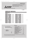
SPLIT-TYPE,HEAT PUMP AIR CONDITIONERS
●MXZ-18NV- E1 and MXZ-18NV- E2 have been added.
●Page layout has been changed.
●Performance curves has been modified.
●The graph of the outdoor low pressure in the HEAT
operation of the PERFORMANCE CURVE of MXZ32NV was deleted.
●Please void OB185 REVISED EDITION A and B.
No. OB185
REVISED EDITION C
SERVICE MANUAL
Inverter-controlled multi system
Models
MXZ-18NV
MXZ-32NV
MXZ-18NV
MXZ-32NV
-
E1
E1
E2
E2
CONTENTS
MXZ-32NV
Model indication
1. TECHNICAL CHANGES ····································2
2. PART NAMES AND FUNCTIONS······················2
3. INDOOR /OUTDOOR
CORRESPONDENCE TABLE··········3
4. INDOOR UNITS COMBINATION ·······················4
5. SPECIFICATION·················································9
6. OUTLINES AND DIMENSIONS························11
7. WIRING DIAGRAM ··········································13
8. REFRIGERANT SYSTEM DIAGRAM ··············15
9. PERFORMANCE CURVES ······························20
10. MICROPROCESSOR CONTROL ····················30
11. TROUBLESHOOTING ······································39
12. DISASSEMBLY INSTRUCTIONS·····················53
13. PARTS LIST······················································57
14. OPTIONAL PARTS ····································BACK
This manual describes technical data of outdoor unit.
For indoor unit refer to the service manuals No.OB207 and OB196 REVISED EDITION A of corresponding
models.
1
TECHNICAL CHANGES
MXZ-18LV- E1 →MXZ-18NV- E1
1. Inverter assembly has changed.
2. Gas pipe thermistors were added.
3. H.P.S. has changed.
MXZ-18NV- E1 →MXZ-18NV- E2
1. MSH-07NV- E2 and MSH-12NV- E2 has been added to the combination of the connectable indoor units.
2. Outdoor unit electronic control P.C. board has changed.
3. The outdoor fan speed control has changed.(HEAT mode single operation : Lo → Hi)
MXZ-32AV- E2 →MXZ-32NV- E1
1. The desital display self-diagnosis function has adopted.
2. The desorption method of LEV has changed the screw method to the one touch method.
3. The position of the electronical parts has changed.
4. The chargeless system has adopted.
5. The scroll compressor has adopted.
6. The micro control P.C.board has simplifed.
7. The fan speed level has becomed 3 levels (Hi / Me / Lo).
8. The low pressure switch has adopted .
9. The ditection of connector deviation has becomed easily.
MXZ-32NV- E1 →MXZ-32NV- E2
1. MCFH-13NV- E2 and MCFH-18NV-
2
E2
has been added to the combination of the connectable indoor units.
PART NAMES AND FUNCTION
Outdoor unit
MXZ-18NV
(back and side)
Air inlet
Piping
Drainage hose
Air outlet
Drain outlet
Air intake
Located on the back
and the left side.
MXZ-32NV
Air in
Model indication
Air out
Air outlet
2
3
INDOOR / OUTDOOR CORRESPONDENCE TABLE
MXZ-18NV
OUTDOOR UNIT
MXZ-18NV- E1
MXZ-18NV- E2
09+09
09+09
-
07+12
MXZ-32NV
Combination of the connectable indoor units
OUTDOOR UNIT
MXZ-32NV- E1
MXZ-32NV- E2
07+07+07
07+07+07
07+07+09
07+07+09
07+07+12
07+07+(12 or 13)
07+07+18
07+07+18
07+09+09
07+09+09
07+09+12
07+09+(12 or 13)
07+09+18
07+09+18
07+12+12
07+(12 or 13)+(12 or 13)
07+12+18
07+(12 or 13)+18
07+18+18
07+18+18
09+09+09
09+09+09
09+09+12
09+09+(12 or 13)
09+09+18
09+09+18
09+12+12
09+(12 or 13)+(12 or 13)
09+12+18
09+(12 or 13)+18
09+18+18
09+18+18
12+12+12
(12 or 13)+(12 or 13)+(12 or 13)
12+12+18
(12 or 13)+(12 or 13)+18
07+07+07+07
07+07+07+07
07+07+07+09
07+07+07+09
07+07+07+12
07+07+07+(12 or 13)
07+07+07+18
07+07+07+18
07+07+09+09
07+07+09+09
07+07+09+12
07+07+09+(12 or 13)
07+07+09+18
07+07+09+18
07+07+12+12
07+07+(12 or 13)+(12 or 13)
07+07+12+18
07+07+(12 or 13)+18
07+09+09+09
07+09+09+09
07+09+09+12
07+09+09+(12 or 13)
07+09+09+18
07+09+09+18
07+09+12+12
07+09+(12 or 13)+(12 or 13)
09+09+09+09
09+09+09+09
09+09+09+12
09+09+09+(12 or 13)
09+09+09+18
09+09+09+18
09+09+12+12
09+09+(12 or 13)+(12 or 13)
❈There is no combination other than this table.
3
4
INDOOR UNITS COMBINATION
MXZ-18NV
Indoor units
combination
Total
Outdoor unit
power consumption
(kW)
2.3
(1.6 - 2.8)
2.5
(1.7 - 3.0)
3.4
(1.8 - 3.8)
4.5
(2.0 - 4.5)
4.5
(1.9 - 4.5)
1.02
(0.855 - 1.33)
1.05
(0.855 - 1.36)
1.45
(0.855 - 1.63)
2.00
(0.91- 2.00)
2.00
(0.91 - 2.00)
Cooling capacity (kW)
Unit A
Unit B
07
2.3
-
09
2.5
-
12
3.4
-
07+12
2.0
2.5
09+09
2.25
2.25
Indoor units
combination
4
NOTE:Electrical data is for outdoor unit only.
Total
Outdoor unit
power consumption
(kW)
3.3
(2.0 - 4.0)
3.6
(2.0 - 4.5)
4.0
(2.2 - 4.7)
5.8
(2.1 - 5.8)
5.8
(2.0 - 5.8)
1.45
(0.69 - 1.60)
1.47
(0.69 - 1.62)
1.63
(0.69 - 1.69)
1.785
(0.69 - 1.785)
1.785
(0.69 - 1.785)
Heating capacity (kW)
Unit A
Unit B
07
3.3
-
09
3.6
-
12
4.0
-
07+12
2.7
3.1
09+09
2.9
2.9
Current
(A)
220V 240V
Power
factor
(%)
5.20
4.72
89 - 90
5.36
4.86
89 - 90
7.40
6.71
89 - 90
10.21 9.26
89 - 90
10.21 9.26
89 - 90
Current
(A)
220V 240V
Power
factor
(%)
7.40
6.71
89 - 90
7.50
6.80
89 - 90
8.32
7.54
89 - 90
9.02
8.26
90 - 90
9.02
8.26
90 - 90
MXZ-32NV
NOTE: Electrical data is for outdoor unit only.
Heating capacity (kw)
Outdoor unit
power consumption
(kw)
Current
(A)
220V 240V
Power
factor
(%)
Indoor units
combination
Unit A
Unit B
Unit C
Unit D
Total
07
2.2
-
-
-
2.2
(1.8-2.7)
1.00
(0.96-1.14)
5.05
4.63
90
09
2.8
-
-
-
2.8
(1.8-3.2)
1.77
(0.96-1.36)
5.91
5.42
90
12(13)
4.0
-
-
-
4.0
(2.2-4.5)
1.42
(1.00-1.63)
7.17
6.57
90
18
5.0
-
-
-
5.0
(2.2-5.4)
1.84
(1.00-1.99)
9.29
8.52
90
07+07
2.2
2.2
-
-
4.4
(3.0-5.4)
1.63
(1.30-2.03)
8.23
7.55
90
07+09
2.2
2.8
-
-
5.0
(3.0-6.0)
1.88
(1.30-2.23)
9.49
8.70
90
07+12(13)
2.2
4.0
-
-
6.2
(3.0-7.2)
2.38
(1.30-2.98)
12.02
11.09
90
07+18
2.2
5.0
-
-
7.2
(3.0-7.6)
2.74
(1.30-2.98)
13.84 12.69
90
09+09
2.8
2.8
-
-
5.6
(3.0-6.4)
2.13
(1.30-2.43)
10.76
9.86
90
09+12(13)
2.8
4.0
-
-
6.8
(3.0-7.6)
2.63
(1.30-2.88)
12.18 12.18
90
09+18
2.8
5.0
-
-
7.8
(3.0-8.6)
3.29
(1.30-3.60)
16.62 15.23
90
12(13)+12(13)
4.0
4.0
-
-
8.0
(3.0-8.8)
3.38
(1.30-3.60)
17.07 15.65
90
12(13)+18
3.5
4.5
-
-
8.0
(3.0-8.8)
3.38
(1.30-3.60)
17.07 15.65
90
18+18
4.0
4.0
-
-
8.0
(3.0-8.8)
3.38
(1.30-3.60)
17.07 15.65
90
07+07+07
2.2
2.2
2.2
-
6.6
(3.7-8.1)
3.23
(1.30-3.96)
17.07 15.65
90
07+07+09
2.2
2.2
2.8
-
7.2
(3.7-8.5)
3.23
(1.30-3.96)
16.31 14.95
90
07+07+12(13)
2.1
2.1
3.8
-
8.0
(3.7-9.0)
3.23
(1.30-3.96)
16.31 14.95
90
07+07+18
1.9
1.9
4.2
-
8.0
(3.7-9.0)
3.23
(1.30-3.96)
16.31 14.95
90
07+09+09
2.2
2.8
2.8
-
7.8
(3.7-8.8)
3.23
(1.30-3.96)
16.31 14.95
90
07+09+12(13)
1.9
2.5
3.6
-
8.0
(3.7-9.0)
3.23
(1.30-3.96)
16.31 14.95
90
07+09+18
1.7
2.3
4.0
-
8.0
(3.7-9.0)
3.23
(1.30-3.96)
16.31 14.95
90
07+12(13)+12(13)
1.8
3.1
3.1
-
8.0
(3.7-9.0)
3.23
(1.30-3.96)
16.31 14.95
90
07+12(13)+18
1.6
2.8
3.6
-
8.0
(3.7-9.0)
3.23
(1.30-3.96)
16.31 14.95
90
07+18+18
1.5
3.25
3.25
-
8.0
(3.7-9.0)
3.23
(1.30-3.96)
16.31 14.95
90
5
NOTE: Electrical data is for outdoor unit only.
Heating capacity (kw)
Outdoor unit
power consumption
(kw)
Current
(A)
220V 240V
Power
factor
(%)
8.0
(3.7-9.0)
3.23
(1.30-3.96)
16.31 14.95
90
-
8.0
(3.7-9.0)
3.23
(1.30-3.96)
16.31 14.95
90
3.8
-
8.0
(3.7-9.0)
3.23
(1.30-3.96)
16.31 14.95
90
3.0
3.0
-
8.0
(3.7-9.0)
3.23
(1.30-3.96)
16.31 14.95
90
1.9
2.7
3.4
-
8.0
(3.7-9.0)
3.23
(1.30-3.96)
16.31 14.95
90
09+18+18
1.8
3.1
3.1
-
8.0
(3.7-9.0)
3.23
(1.30-3.96)
16.31 14.95
90
12(13)+12(13)
+12(13)
2.67
2.67
2.67
-
8.0
(3.7-9.0)
3.23
(1.30-3.96)
16.31 14.95
90
12(13)+12(13)+18
2.45
2.45
3.1
-
8.0
(3.7-9.0)
3.23
(1.30-3.96)
16.31 14.95
90
07+07+07+07
2.0
2.0
2.0
2.0
8.0
(3.7-9.0)
3.23
(1.30-3.96)
16.31 14.95
90
07+07+07+09
1.87
1.87
1.87
2.4
8.0
(3.7-9.0)
3.23
(1.30-3.96)
16.31 14.95
90
07+07+07+12(13)
1.7
1.7
1.7
2.9
8.0
(3.7-9.0)
3.23
(1.30-3.96)
16.31 14.95
90
07+07+07+18
1.5
1.5
1.5
3.5
8.0
(3.7-9.0)
3.23
(1.30-3.96)
16.31 14.95
90
07+07+09+09
1.8
1.8
2.2
2.2
8.0
(3.7-9.0)
3.23
(1.30-3.96)
16.31 14.95
90
07+07+09+12(13)
1.6
1.6
2.0
2.8
8.0
(3.7-9.0)
3.23
(1.30-3.96)
16.31 14.95
90
07+07+09+18
1.5
1.5
1.8
3.2
8.0
(3.7-9.0)
3.23
(1.30-3.96)
16.31 14.95
90
07+07+12(13)
+12(13)
1.4
1.4
2.6
2.6
8.0
(3.7-9.0)
3.23
(1.30-3.96)
16.31 14.95
90
07+07+12(13)+18
1.3
1.3
2.4
3.0
8.0
(3.7-9.0)
3.23
(1.30-3.96)
16.31 14.95
90
07+09+09+09
1.7
2.1
2.1
2.1
8.0
(3.7-9.0)
3.23
(1.30-3.96)
16.31 14.95
90
07+09+09+12(13)
1.5
1.9
1.9
2.7
8.0
(3.7-9.0)
3.23
(1.30-3.96)
16.31 14.95
90
07+09+09+18
1.4
1.75
1.75
3.1
8.0
(3.7-9.0)
3.23
(1.30-3.96)
16.31 14.95
90
07+09+12(13)
+12(13)
1.35
1.75
2.45
2.45
8.0
(3.7-9.0)
3.23
(1.30-3.96)
16.31 14.95
90
09+09+09+09
2.0
2.0
2.0
2.0
8.0
(3.7-9.0)
3.23
(1.30-3.96)
16.31 14.95
90
09+09+09+12(13)
1.8
1.8
1.8
2.6
8.0
(3.7-9.0)
3.23
(1.30-3.96)
16.31 14.95
90
09+09+09+18
1.67
1.67
1.67
3.0
8.0
(3.7-9.0)
3.23
(1.30-3.96)
16.31 14.95
90
09+09+12(13)
+12(13)
1.65
1.65
2.35
2.35
8.0
(3.7-9.0)
3.23
(1.30-3.96)
16.31 14.95
90
Indoor units
combination
Unit A
Unit B
Unit C
Unit D
Total
09+09+09
2.67
2.67
2.67
-
09+09+12(13)
2.3
2.3
3.4
09+09+18
2.1
2.1
09+12(13)+12(13)
2.0
09+12(13)+18
6
NOTE: Electrical data is for outdoor unit only.
Heating capacity (kw)
Outdoor unit
power consumption
(kw)
Current
(A)
220V 240V
Power
factor
(%)
Indoor units
combination
Unit A
Unit B
Unit C
Unit D
Total
07
3.4
-
-
-
3.4
(2.1-3.6)
1.20
(0.91-1.28)
6.06
5.55
90
09
4.0
-
-
-
4.0
(2.1-4.2)
1.43
(0.91-1.51)
7.22
6.62
90
12(13)
6.0
-
-
-
6.0
(2.2-6.3)
1.79
(0.94-1.88)
9.04
8.29
90
18
7.1
-
-
-
7.1
(2.2-7.5)
2.10
(0.94-2.21)
10.61
9.72
90
07+07
3.4
3.4
-
-
6.8
(4.1-7.2)
1.98
(1.13-2.18)
10.00
9.17
90
07+09
3.4
4.0
-
-
7.4
(4.1-7.8)
2.23
(1.13-2.33)
11.26 10.32
90
07+12(13)
3.35
5.95
-
-
9.3
(4.1-9.7)
2.82
(1.13-2.96)
14.24 13.05
90
07+18
2.85
6.45
-
-
9.3
(4.1-9.7)
2.82
(1.13-2.96)
14.24 13.05
90
09+09
4.0
4.0
-
-
8.0
(4.1-8.4)
2.38
(1.13-2.54)
12.02 11.01
90
09+12(13)
3.7
5.6
-
-
9.3
(4.1-9.7)
2.82
(1.13-2.96)
14.24 13.05
90
09+18
3.35
5.95
-
-
9.3
(4.1-9.7)
2.82
(1.13-2.96)
14.24 13.05
90
12(13)+12(13)
4.65
4.65
-
-
9.3
(4.1-9.7)
2.82
(1.13-2.96)
14.24 13.05
90
12(13)+18
4.3
5.0
-
-
9.3
(4.1-9.7)
2.82
(1.13-2.96)
14.24 13.05
90
18+18
4.65
4.65
-
-
9.3
(4.1-9.7)
2.82
(1.13-2.96)
14.24 13.05
90
07+07+07
3.1
3.1
3.1
-
9.3
(5.2-10.6)
2.78
(1.19-2.96)
14.04 12.87
90
07+07+09
2.95
2.95
3.4
-
9.3
(5.2-10.6)
2.78
(1.19-2.96)
14.04 12.87
90
07+07+12(13)
2.5
2.5
4.3
-
9.3
(5.2-10.6)
2.78
(1.19-3.96)
14.04 12.87
90
07+07+18
2.3
2.3
4.7
-
9.3
(5.2-10.6)
2.78
(1.19-2.96)
14.04 12.87
90
07+09+09
2.8
3.25
3.25
-
9.3
(5.2-10.6)
2.78
(1.19-2.96)
14.04 12.87
90
07+09+12(13)
2.4
2.8
4.1
-
9.3
(5.2-10.6)
2.78
(1.19-2.96)
14.04 12.87
90
07+09+18
2.2
2.6
4.5
-
9.3
(5.2-10.6)
2.78
(1.19-3.96)
14.04 12.87
90
07+12(13)+12(13)
2.0
3.65
3.65
-
9.3
(5.2-10.6)
2.78
(1.19-2.96)
14.04 12.87
90
07+12(13)+18
1.9
3.4
4.0
-
9.3
(5.2-10.6)
2.78
(1.19-2.96)
14.04 12.87
90
07+18+18
1.9
3.75
3.75
-
9.3
(5.2-10.6)
2.78
(1.19-2.96)
14.04 12.87
90
7
NOTE: Electrical data is for outdoor unit only.
Heating capacity (kw)
Outdoor unit
power consumption
(kw)
Current
(A)
220V 240V
Power
factor
(%)
9.3
(5.2-10.6)
2.78
(1.19-2.96)
14.04 12.87
90
-
9.3
(5.2-10.6)
2.78
(1.19-2.96)
14.04 12.87
90
4.4
-
9.3
(5.2-10.6)
2.78
(1.19-2.96)
14.04 12.87
90
3.5
3.5
-
9.3
(5.2-10.6)
2.78
(1.19-2.96)
14.04 12.87
90
2.2
3.3
3.8
-
9.3
(5.2-10.6)
2.78
(1.19-2.96)
14.04 12.87
90
09+18+18
2.0
3.65
3.65
-
9.3
(5.2-10.6)
2.78
(1.19-2.96)
14.04 12.87
90
12(13)+12(13)
+12(13)
3.1
3.1
3.1
-
9.3
(5.2-10.6)
2.78
(1.19-2.96)
14.04 12.87
90
12(13)+12(13)+18
2.86
2.86
3.58
-
9.3
(5.2-10.6)
2.78
(1.19-2.96)
14.04 12.87
90
07+07+07+07
2.32
2.32
2.32
2.32
9.3
(5.2-10.6)
2.78
(1.19-2.96)
14.04 12.87
90
07+07+07+09
2.2
2.2
2.2
2.7
9.3
(5.2-10.6)
2.78
(1.19-2.96)
14.04 12.87
90
07+07+07+12(13)
2.0
2.0
2.0
3.3
9.3
(5.2-10.6)
2.78
(1.19-2.96)
14.04 12.87
90
07+07+07+18
1.9
1.9
1.9
3.6
9.3
(5.2-10.6)
2.78
(1.19-2.96)
14.04 12.87
90
07+07+09+09
2.15
2.15
2.5
2.5
9.3
(5.2-10.6)
2.78
(1.19-2.96)
14.04 12.87
90
07+07+09+12(13)
1.9
1.9
2.2
3.3
9.3
(5.2-10.6)
2.78
(1.19-2.96)
14.04 12.87
90
07+07+09+18
1.75
1.75
2.1
3.7
9.3
(5.2-10.6)
2.78
(1.19-2.96)
14.04 12.87
90
07+07+12(13)
+12(13)
1.7
1.7
2.95
2.95
9.3
(5.2-10.6)
2.78
(1.19-2.96)
14.04 12.87
90
07+07+12(13)+18
1.6
1.6
2.8
3.3
9.3
(5.2-10.6)
2.78
(1.19-2.96)
14.04 12.87
90
07+09+09+09
2.1
2.4
2.4
2.4
9.3
(5.2-10.6)
2.78
(1.19-2.96)
14.04 12.87
90
07+09+09+12(13)
1.8
2.15
2.15
3.2
9.3
(5.2-10.6)
2.78
(1.19-2.96)
14.04 12.87
90
07+09+09+18
1.7
2.0
2.0
3.6
9.3
(5.2-10.6)
2.78
(1.19-2.96)
14.04 12.87
90
07+09+12(13)
+12(13)
1.6
1.9
2.9
2.9
9.3
(5.2-10.6)
2.78
(1.19-2.96)
14.04 12.87
90
09+09+09+09
2.32
2.32
2.32
2.32
9.3
(5.2-10.6)
2.78
(1.19-2.96)
14.04 12.87
90
09+09+09+12(13)
2.05
2.05
2.05
3.15
9.3
(5.2-10.6)
2.78
(1.19-2.96)
14.04 12.87
90
09+09+09+18
1.95
1.95
1.95
3.45
9.3
(5.2-10.6)
2.78
(1.19-2.96)
14.04 12.87
90
09+09+12(13)
+12(13)
1.85
1.85
2.8
2.8
9.3
(5.2-10.6)
2.78
(1.19-2.96)
14.04 12.87
90
Indoor units
combination
Unit A
Unit B
Unit C
Unit D
Total
09+09+09
3.1
3.1
3.1
-
09+09+12(13)
2.65
2.65
4.0
09+09+18
2.45
2.45
09+12(13)+12(13)
2.3
09+12(13)+18
8
Outdoor unit
Electrical data ✻ 1
Capacity
System
5
SPECIFICATION
Model
Indoor units number
Piping total length
Connecting pipe length
Height difference (indoor ~ outdoor)
Height difference (indoor ~ indoor)
Capacity
Cooling
Sound level
Capacity
Booster heater
Heating
Sound level
Power supply
Mode
Power consumption
Running current
Power factor
Crankcase heater
Starting current
Compressor motor current
Fan motor current
External finish
Height
Width
Dimensions
Depth
Weight
Refrigerant filling capacity (R-22)
Refrigerating oil
<Model>
In/Out connecting wire (Each room)
Liquid pipe
Refrigerant
Gas pipe
piping
Connection method
Compressor
Protective
Fan motor
device
Model
Output
Compressor
Winding resistance (at 20 :)
Model
Output
Fan motor
Winding resistance (at 20 :)
Air flow amount change
Fan speed
Air flow
Power outlet
RT61 (at 25:)
RT62 (at 100:)
RT63 (at 70:)
Thermistor
RT64 (at 25:)
RT65 (at 25:)
RT66, 67 (at 25:)
TEST CONDITIONS COOLING INDOOR
OUTDOOR
HEATING INDOOR
OUTDOOR
m
m
m
m
kW
dB
kW
W
dB
W
A
%
W
A
A
A
mm
mm
mm
kg
kg
cc
mm
mm
W
"
W
"
rpm
K/h
A
DB27.0°C WB19.0°C
DB35.0°C WB24.0°C
DB20.0°C
DB 7.0°C WB 6.0°C
MXZ-18NV- E1 MXZ-18NV- E2
2
Max. 30
Max. 20
Max. 7
Max. 7
4.5 (1.7 ~ 4.5)
45
5.8 (2.0 ~ 5.8)
46
Single phase, 220-240V, 50Hz
Cooling
Heating
2,000 (855~2000)
1,785 (690~1785)
10.21(5.28 - 10.21) - 9.26(4.83 - 9.26)
9.02(6.38 - 9.02) - 8.26(5.83 - 8.26)
89 - 90
90 - 90
10.21
9.74(4.87 - 9.74) - 8.86(4.43 - 8.86)
8.62(5.98 - 8.62) - 7.86(5.43 - 7.86)
0.4
Munsell 5Y 7/1
650
875
295 (+30)
56
1.3
570cc <MS-56>
2-core, 1pc. [2.0mm
[9.52 (2pcs)
[6.35 (2pcs)
Flared
✻2
Inner thermostat
RHV-207FEM (Rotary)
1,100
1.195(U-V, V-W, W-U)
RA6V50 50
BLK-WHT 163, BLK-YLW 72, YLW-RED 36
2
630-670
2,460 - 2,580
25
10.0k"
13.4k"
7.9k"
10.0k"
10.0k"
10.0k"
✽2 Current detection
Discharge temperature detection
High-pressure switch
✽1 Electrical data is for only outdoor unit.
9
System
Capacity
Electrical data ✻ 1
Outdoor unit
Model
Indoor units number
Piping total length
Connecting pipe length
Height difference (indoor ~ outdoor)
Height difference (indoor ~ indoor)
Capacity
Cooling
Sound level
Capacity
Booster heater
Heating
Sound level
Power supply
Mode
Power consumption
Running current
Power factor
Crankcase heater
Starting current
Compressor motor current
Fan motor current
External finish
Height
Width
Dimensions
Depth
Weight
Refrigerant filling capacity (R-22)
Refrigerating oil <Model>
In/Out connecting wire (Each room)
Liquid pipe
Refrigerant
Gas pipe
piping
Connection method
Compressor
Protective
Fan motor
device
Model
Output
Compressor
Winding resistance (at 20 :)
Model
Output
Fan motor
Winding resistance (at 20 :)
Air flow amount change
Fan speed
Air flow
Power outlet
RT61 (at 100:)
RT62 (at 25:)
RT63 (at 50:)
Thermistor
RT64 (at 25:)
RT65 (at 25:)
RT70,66, 67,68,69 (at 25:)
TEST CONDITIONS COOLING INDOOR
OUTDOOR
HEATING INDOOR
OUTDOOR
✽1 Electrical data is for only outdoor unit.
10
m
m
m
m
kW
dB
kW
W
dB
W
A
%
W
A
A
A
mm
mm
mm
kg
kg
cc
mm
mm
W
"
W
"
rpm
K/h
A
MXZ-32NV- E1 MXZ-32NV- E2
3-4
Max. 60
Max. 25
Max. 10
Max. 10
8.0 (1.8 ~ 9.0)
45-47
9.3 (2.1 ~ 10.6)
46-48
Single phase, 220-240V, 50Hz
Cooling
Heating
3,230 (960~3,960)
2,780 (910~2,960)
16.31(4.85 - 20.00) - 14.95(4.44 - 18.33)
90
25
16.31 - 14.95
15.71(4.25 - 19.40) - 14.35(3.84 - 17.73) 13.44(4.00 - 14.35) - 12.27(3.62 - 13.10)
0.4
Munsell 5Y 8/1
900
900
320 (+35)
83.5
4.2
1070cc <MS-32>
2-core, 1pc. [2.0mm
[12.7 (2pcs) [9.52 (2pcs)
[6.35 (4pcs)
Flared
✻2
Inner thermostat
CHV253FAA (Scroal)
2,000
0.54(U-V, V-W, W-U)
RA6V6060
BLK-WHT 79.0, BLK-YLW 27.0, YLW-BLU 12.0 BLU-RED 84.0
3
630 - 680 / 525 - 570 / 460 - 500
3000 / 2400 / 2100
25
13.4k"
10.0k"
17.0k"
10.0k"
10.0k"
10.0k"
DB27.0°C WB19.0°C
DB35.0°C WB24.0°C
DB20.0°C
DB 7.0°C WB 6.0°C
✽2 Current detection
Discharge temperature detection
High-pressure switch
Crankcase heater
Low-pressure switch
Inner thermostat
Rear piping
hole
Handle for
monving
10
Max. 10 units
200
Side
Rear air-intake
air-intake
1000
23
100
7
295
Air in
Handle for
moving
Outlet guide
mounting hole
505
30
40
Drain hole
339
524
870
A
B
Drain hole
2-U-Shape noched hols
(Base bolt M10)
2 Oval hols (12 13)
(Base bolt M10)
302
Air out
27.5
39.5
12
Ground
terminal
116
10
Leave overhead
clearance fully
10
500
Base bolt length
To drain water in a mass, use
optional drain pan and drain
socket.
Drain pan : PAC-928DP,PAC-SA44DP
Drain socket : PAC-SA46DS
25
10
Leave front clearance fully
Space for servicing
(flared 9.52)
Gas pipe
(flared 6.35)
Liquid pipe
Handle for moving
2
Leave overhead clearance fully
33
524
77
362
57
Necessary surrounding clearance for concentrated installation.
185
500
17
330
15
57
107
Air in
R6
500
Max. 25
185
17
57
500
Necessary surrounding clearance
650
200
100
6
OUTLINES AND DIMENSIONS
MXZ-18NV - E1 MXZ-18NV - E2
Unit:mm
11
1.Installation space
12
More than
100
More than
500
317
900
(Base bolt M10)
2-12 ✕ 36 Oval hole
(Base bolt M10)
2-U-shape notched holes
27
Indoor and outdoor
connect wiring
23✕45 hole
40
Air in
35
Air out
200
(16)
Air in
320
Air in
Air in
500
355
10
Service space
More than
350
200
Note : Leave front, overhead and
both clearance fully.
387
Handle for
moving
Note : Leave front and overhead
clearance fully.
Base
(16)
More than
500
More than
10
2.Service space
More than
200
More than
350
More than
500
Note : Leave front and both sides
clearance fully.
More than
500
Veranda
Base bollt length
Less than
25
More than
10
More than
100
480.8
350.0
50
23
900
531.3
460
33
23
A unit connection
B unit connection
C unit connection
D unit connection
[ 6.35 (flared) 1/4
Liquid pipe
88
[ 9.52 (flared) 3/8 (C , D unit)
[ 12.7 (flared) 1/2 (A , B unit)
Rubber cushion
MXZ-32NV - E1 MXZ-32NV - E2
Unit:mm
7
WIRING DIAGRAM
MXZ-18NV-
E2
V
L
WHT
NAME
SURGE ABSORBER
C61
POWER-FACTOR CAPACITOR
RED
ORN
BLU
YLW
GRN
RED
TR
❈V
❈W
YLW
ORN
BLK
WHT
RED
RED
YLW
GRN
BLU
4 3 2 1
CN61
1 2 3 4 5 6
TAB91
CN63
CN731
C65
X67
FUSE2
ELECTRONIC CONTROL
P.C.BOARD
X60
LEV A
RT63
RT64
RT65
RT66
RT67
RT61
RED
RT67
EVAPORATION TEMPERATURETHERMISTOR
CMC COIL
R64
CURRENT-LIMITING RESISTOR
COMPRESSOR
R65
CURRENT-DETECTING RESISTOR
C65
OUTDOOR FAN CAPACITOR
MF
OUTDOOR FAN MOTOR(INNER THERMOSTAT)
FUSE(1A)
BLU
LEV A,B EXPANSION VALVE
MC
FUSE1
GRN
SUCTION TEMPERATURETHERMISTOR
L61
DS61,63 DIODE MODULE
YLW
RT66
CERAMIC CAPACITOR
SMOOTHING CAPACITOR
ORN
NAME
SYMBOL
CERAMIC CAPACITOR
CURRENT TRANSFORMER
RED
REACTOR
L
C63
CT61
BRN
HPS
C64
C67
8
7
6
5
4
3
2
1
LEV B
NAME
SYMBOL
GRY
1 2
GRY
CN671
4 3 2 1
GRY
CN641
1 2 3 4
GRY
CN681
1 2 3 4
GRY
CN683
1 2
GRY
CN661
GRY
CN682
1 2 3
GRY
CN771
1 2 3 4 5 6
GRY
CN761
1 2 3 4 5
RT62
AR61
RED
RED
BLK
ORN
BLU
1 2
CN621
T801
1 2
FUSE1
SSR61
RELAY P.C.BOARD
SYMBOL
WHT
BuP EuP BvP EvP BwPEwP
GRY
R64
1 2
CN801
BLK
1
2
3
4
5
6
BLU
BLK
4
❈
1
2
3
BLK
BuN EuN BvN EvN BwN EwN
BLK
3
R65
21S4
RED
LD64
❈
RED
BLU
1
2
3
4
BLU
AR61
❈
BRN
YLW
YLW
YLW
RED
BLU
BLK
CT61
X64
NR61
1
2
3
4
❈
BLU
❈ ❈
LD63
TB62
TB61
LD77
DS61
F62
LD62
LDE1
LD74
C64
BLU
❈❈ ❈
LD61
C63
RED
LD72
WHT
❈
YLW
❈
-
TBAC1
GRN
+
ORN
❈
TBAC2
+
~
~
~
RED
BLU
❈ ❈ ❈
WHT
❈
-
YLW
❈
RED
❈ P ❈U
❈N
CN611
RED
~
RED
RED
CN601
❈
WHT
LD73
L61
BLU
DC24V 3
❈
❈
BLK
+
RED
BLK
LD71
C61 RED
ORN
BLU
CN941
RED
❈
- C67
❈
WHT
WHT
❈
❈ DS63
~ ❈
❈
+
BLK
❈
❈
❈
BLK
3
1
MF
MC W
WHT
U
❈ NF61
4❈
❈
BLK
❈
❈
2
BLK
N
N
3
1
RED
TB
❈ NF62
4❈
BRN
BLU
DC24V 3
INDOOR
TO
UNIT (B)
INDOOR
UNIT
CONNECTING
INDOOR
UNIT (A)
BLU
BRN
BLU
BRN
POWER SUPPLY
N
❈
220-240V
~/N
L
❈
50Hz
CIRCUIT BREAKER
2
BRN
WHT
GRN/YLW
BLK
TB
CN701
E1
RED
MODELS MXZ-18NV-
NF61,62 NOISE FILTER
NR61
VARISTOR
RT61
DEFROST TEMPERATURETHERMISTOR
RT62
DISCHARGE TEMPERATURETHERMISTOR
SSR61
SOLID STATE RELAY
TB
TERMINAL BLOCK
TR
POWER TRANSISTOR MODULE
T801
X60,67
TRANSFORMER
FAN MOTOR RELAY
FUSE2
FUSE(3.15A)
RT63
FIN TEMPERATURETHERMISTOR
X64
RELAY
F62
FUSE(3.15A)
RT64
GAS PIPE TEMPERATUREB.THERMISTOR
21S4
R.V.COIL
HPS
HIGH PRESSURE SWITCH
RT65
GAS PIPE TEMPERATUREA.THERMISTOR
NOTE:1. For the outdoor electric wining refer to the outdoor unit electric wining diagram for servicing.
2. Use copper conductors only.(For field wining)
3. Symbols below indicate.
: Terminal block,
: Connector
4. “ ✻ ”shows the terminals with a lock mechanism,so they cannnot be removed when you pull
the lead wire.
Be sure to pull the wire by pushing the locking lever (project part) of the terminal with a finger.
1.Slide the sleeve.
2.Pull the wire while
pushing the locking
lever.
13
MXZ-32NV-
LDE
LEV A
SYMBOL
C61
C62,63
C65
CH
CT61,62
DS61
DS62
F801
F911
L
L61
LEV A~D
R
RT61
RT62
RT63
RT64
21S4
21S2
CH
LEV B
LEV C
CN794
1 2 3456
LEV D
CN722
1 2 34
63H1 63L
NAME
POWER FACTOR CAPACITOR
SMOOTHING CAPACITOR
OUTDOOR FAN CAPACITOR
CRANKCASE HEATER
CURRENT TRANSFORMER
DIODE MODULE
DIODE STACK
FUSE (1A)
FUSE (1A)
REACTOR
COMMON MODE CHOKE COIL
EXPANSION VALVE
RESISTOR
DISCHARGE TEMPERATURE THERMISTOR
DEFROST TEMPERATURE THERMISTOR
FIN TEMPERATURE THERMISTOR
EVAPORATION TEMPERATURE THERMISTOR
7 65 43 2 1
CN515
YLW
BLU
CN663
CN662
1 2
1 2 3456 78
RT63 RT66
RT68
RT67
RT62
RT69
3
N
C UNIT
3
N
B UNIT
3
N
A UNIT
3
N
Indoor/outdoor connecting wire
SYMBOL
RT65
RT66,67
RT68,69
MC
MF61
SSR61,62
SSR63
T801
TB2,3,4
X61,62,63
X64,65
X66,67
21S2
21S4
63H1
63H2
63L
Make all connections
as shown below.
B UNIT
Terminal block
POWER SUPPLY
~/N 220-240V 50Hz
3
2
N
L
Power supply cord
A UNIT
14
RT65
WHT
WHT
X65
X67
YLW
1.Slide the sleeve.
2.Pull the wire while
pushing the locking
lever.
INDOOR UNIT
C UNIT
YLW
NAME
SUCTION TEMPERATURE THERMISTOR
GUS PIPE TEMPERATURE THERMISTOR
GUS PIPE TEMPERATURE THERMISTOR
COMPRESSOR
OUTDOOR FAN MOTOR (INNER FUSE)
SOLENOID COIL RELAY
CRANKCASE HEATER RELAY
TRANSFORMER
TERMINAL BLOCK
FAN MOTOR RELAY
RELAY
RELAY
SOLENOID COIL
R.V. COIL
HIGH PRESSURE SWITCH
HIGH PRESSURE SWITCH
LOW PRESSURE SWITCH
D UNIT
GROUND
N
L
TAB66
RT64
RT61
INDOOR AND OUTDOOR ELECTRICAL WIRING CONNECTION FIGURE
D UNIT
TAB65
CN661
1 2 3456 78
NOTE:1. “- - - - “ denotes the wiring at the site.
2 “❈”show the terminals with a lock mechanism, so they cannot be removed
when you pull the lead wire.
Be sure to pull the wire by pushing the locking lever(projected part) of the
terminal with a finger.
OUTDOOR UNIT
RELAY
P.C. BOARD
CT62
ELECTRONIC CONTROL P.C. BOARD
CN793
1 2 3456
ORN
GRY
GRY
BLK
BLK
GRY
GRY
GRY
GRY
CN792
1 2 3456
CN852
ORN
W
I.P.M P.C. BOARD
MF61
GRY
GRY
GRY
GRY
GRY
GRY
GRY
GRY
CN851
X66
43 21
CN501
X61
X62
X63
RED
ORN
WHT
BLK
WHT
4
BLK
BLK
CN791
1 2 3456
RED
BRN
BLU
ORN
YLW
WHT
3
6
1 2 3456
WHT
BLU
BEN
GRN/YLW
RED
RED
BLK
BLK
N
12VDC
CN913
CN912
1 2 34
1 2
RED
RED
BLU
BLU
BLU
YLW
12VDC
3
1 2
BLU
ORN
N
CN902
1 23
CN723
N
CN901
RED
BRN
BLU
ORN
YLW
WHT
3
1 2
12VDC
1 2
3
1 2
12VDC
CN720
BLU
RED
RED
BRN
BLU
ORN
YLW
WHT
TB3
CN604 CN603 CN602 CN601
N
1 2 34567
CN705
1 2
INDOOR
UNIT (A)
INDOOR
UNIT (B)
INDOOR
UNIT (C)
INDOOR
UNIT (D)
TAB64
T801
C65
RED
BRN
BLU
ORN
YLW
WHT
BRN
CIRCUIT BRAKER
F911
MC
U
X67
LD61
2
V
BLK
BLU
L61
SSR63
N
SSR61
LD62
GRY
BLK
CN704
L
BLK
NOISE FILTER
P.C.BOARD
LDB
X64
0 1
TB2
CT
61
SSR62
X64 4 6 BLK
LD64
GRN/YLW
1 2 34
CN801
POWER SUPPLY
~/N 220-240V 50Hz
LDB
LD63
TB4
BLK
YLW
CN551
YLW
REDR BLK
RED
-
YLW
RED
WHT
-
WHT
TAB62
-
C63
C62
+ RED +
L
K
(1A)
A
ORN
F801 TAB63
-
CN514
WHT
2 1
DS61
C61
+ ORN +
RED
BLK
CN554
DS62
CN553
GRY
2 1
BRN
X65
E2
CN552
E1
X66
MODELS MXZ-32NV-
63H2
8
REFRIGERANT SYSTEM DIAGRAM
8.1 REFRIGERANT SYSTEM DIAGRAM
MXZ-18NV - E1 MXZ-18NV - E2
Unit:mm
Refrigerant flow in cooling
Refrigerant flow in heating
Service
port
(Low pressure)
Compressor
Discharge
temperature
thermistor
RT62
High pressure
switch
Muffler
Service
port
(high pressure)
Reversing
valve
Gas pipe
thermistor
9.52
Indoor unit
A
Indoor unit
B
Ball valve
Charge port
9.52
Gas pipe
thermistor
Suction temperature
thermistor
RT66
Capillary
tube
4.0X
6.35
Expansion
Strainer valve(LEV) 2.4X
300
Ball valve with
service port
Indoor unit
A
Indoor unit
B
Evaporation
temperature
thermistor
RT67
2.0X 0.6X500
Strainer
Capillary
6.35
Expansion tube
Strainer valve(LEV)
4.0X
2.4X
300
Outdoor
heat
exchanger
Capillary
tube
Defrost
thermistor
RT61
9.52
Capillary
tube
4.0X
2.4X
400
R.V. coil
heating ON
cooling OFF
Low pressure switch
MXZ-32NV - E1 MXZ-32NV - E2
Refrigerant flow in cooling
Refrigerant flow in heating
Suction
temperature
thermistor
[16
Compressor
High pressure
switch 1
High pressure
switch 2
Discharge
temperature
thermistor
Capillary tube
Oil
separator
[2.5✕ [0.6✕1000
Unit D gas pipe temperature thermistor
[9.52
Indoor unit
D
Unit C gas pipe temperature thermistor
Indoor unit
C
Indoor unit
B
R.V. coil
heating ON
cooling OFF
Accumlator
Capillary tube
[3.0✕[2.0✕ 500
Capillary tube
Ball valve with
service port
[3.0✕[2.0✕500
[9.52
2-way-valve
Reversing valve
Unit B gas pipe temperature
thermistor
[12
[16
Unit A gas pipe
temperature thermistor
[16
[12
Indoor unit
A
Evaportation
temperature
thermistor
(RT67)
Indoor unit
A
Strainer
LEV
Strainer
Strainer
LEV
Strainer
Strainer
LEV
Strainer
Strainer
LEV
Strainer
Indoor unit
B
Indoor unit
C
Indoor unit
D
[6
Ball valve with
service port
Capillary tube
[2.5✕[0.6✕ 750
Capillary tube
[4.0✕[2.4✕ 400
Defrost
thermistor
[6
[6
Outdoor
heat
exchanger
Strainer
Distributor
Distributor
[9.52
[6
15
8.2 MAX REFRIGERANT PIPING LENGTH
MXZ-18NV - E1 MXZ-18NV - E2
Piping length for each indoor unit (a,b)
a
Outodoor
unit
20m
Total piping length (a+b)
30m
Height difference between units (H)
7m
Bending point for each unit
15
Total bending point
30
H
H
H
b
❈ It does not matter which unit is higher
MXZ-32NV - E1 MXZ-32NV - E2
Indoor
units
a
b
Outdoor
unit
Piping length each indoor unit (a, b, c, d)
25m
Total piping length (a+b+c+d)
60m
Height difference between units (H)
10m
Bending point for each unit
15
Total bending point
30
❋It does not matter which unit is higher.
16
H
H
c
H
d
8.3 PIPE SIZE SELECTION
MXZ-18NV - E1 MXZ-18NV - E2
● Refrigerant pipe diameter is different according to indoor unit to be connected. When using extension pipes, refer to the
table below.
● When diameter of refrigerant pipe is different from that of outdoor unit union, use optional L-joint. For further information on
L-joint, see page 62.
Unit : mm (inch)
Indoor unit
class
07/09
12
Extention pipe diameter
Pipe diameter
Liquid
6.35(1/4)
Liquid
6.35(1/4)
Gas
9.52(3/8)
Gas
9.52(3/8)
Liquid
6.35(1/4)
Liquid
6.35(1/4)
Gas
12.7(1/2)
Gas
12.7(1/2)
Outdoor unit union diameter
For
Indoor unit A
Indoor unit B
Liquid
6.35(1/4)
Gas
9.52(3/8)
Liquid
6.35(1/4)
Gas
9.52(3/8)
MXZ-32NV - E1 MXZ-32NV - E2
●Refrigerant pipe diameter is different according to indoor unit to be connected. When using extention pipes,refer to the tables
below.
●When diameter of refrigerant pipe is different from that of outdoor unit union, use optional Different-diameter pipe. For further
information on Different-diameter pipe,see page 62.
Unit : mm (inch)
Indoor unit
class
07/09
12(13)
18
Pipe diameter
Extention pipe diameter
Liquid
6.35(1/4)
Liquid
6.35(1/4)
Gas
9.52(3/8)
Gas
9.52(3/8)
Liquid
6.35(1/4)
Liquid
6.35(1/4)
Gas
12.7(1/2)
Gas
12.7(1/2)
Liquid
6.35(1/4)
Liquid
6.35(1/4)
Gas
15.88(5/8)
Gas
15.88(5/8)
Outdoor unit union diameter
For
Indoor unit A
Indoor unit B
Indoor unit C
Indoor unit D
Liquid
6.35(1/4)
Gas
12.7(1/2)
Liquid
6.35(1/4)
Gas
12.7(1/2)
Liquid
6.35(1/4)
Gas
9.52(3/8)
Liquid
6.35(1/4)
Gas
9.52(3/8)
17
8.4 EVACUATION PROCEDURES
MXZ-18NV - E1 MXZ-18NV - E2
CAUTION : If you run this unit with air in its refrigerant pipe before air purge, the compressor will decline in cooling
capacity, which may result in trouble.
❶. Connect the refrigerant pipes (both the liquid and gas pipes) between the indoor and the uotdoor units.
❷. Remove the service port cap of the stop valve on the side of the outdoor unit gas pipe.[ The stop valve
will not work in its initial atate fresh out of the factory (totally closed with cap on).]
❸. Connect the gauge manifold valve and the vacuum pump to the service port of the stop valve on the side
of the outdoor unit gas pipe.
Service port
Gauge manifold valve
Connect pipes
Vacuum pump
❹. Run the vacuum pump.
❺. Check the vacuum with the gauge manifold valve, then close the gauge manifold valve, and stop the
vacuum pump.
❻. Leave it as is for one or two minutes.Make sure the pointer of the gauge manifold valve remains in the
same position.
❼. Remove the cape from the stop valves of the outdoor unit, liquid pipe, and gas pipe. Pull the handle
towards you with a finger. Turn it one fourth turn counterclockwise, to obtain the full-open position.
❽. Remove the cape manifold valve quickly from the service port of the stop valve.
❾. Tishten the cap to the service port to obtain the initial status.
❿. Thrust the handle of the stop valve into the unit, then retighten the cap.
Leak test
....... With a gas detector or soap water, check the flared nut connections for any refrigerant leak.
In case of a refrigerant leak
● Retighten the flared nut connections.
● If the leak does not stop even after retightening, repair the leaking point, collect all from inside the unit
through the service port, apply a vacuum to it, then charge a specified amount of gas with a gas cylinder.
18
MXZ-32NV - E1 MXZ-32NV - E2
● For details about how to use manifold valves, see the instruction manual for manifold valves.
● The valve knob Hi below cannot operate during the following work if it is fully closed.
Warning : When installing or moving the unit, do not mix anything other than specified refrigerant (R-22) into the
refrigerating cycle.
If air is mixed, it may cause the refrigerating cycle to get abnormally high temperature, causing a risk of
burst.
❶. Make sure the pipes are connected securely.
❷. Connect the projected side (on which the setting pin is pressed) of the gauge manifold valve´s charge hose to the
stop valve´s service port (gas pipe side).
❸. Make sure the stop valves of gas and liquid pipes are fully closed, and connect the charge house to the vacuum
pump.
Compound gauge Pressure gauge
-1.01✕10 Pa
(-760mmHg)
Stop valve
(gas side)
Valve knob Lo
Gauge
Manifold
Valve knob Hi
Service port
Vacuum
pump
Charge hose
❹. Fully open the manifold valve´s valve knob Lo and operate the vacuum pump.
Loosen the stop valve flare nut on the gas pipe side a little bit and make sure that air is entering.
Then tighten the flare nut not to enter the air. After that, make sure that the charge hose is connected firmly to
the service port.
❺. Purge air for more than 15 minutes, and make sure the compound gauge is reading - 1.01 ✕ 105 Pa (-760mmHg).
❻. After purging air, fully close the manifold valve´s valve knob Lo and stop operating the vacuum pump.
❼. Leave the situation for about 1 to 2 minutes, make sure the needle of the compound gauge does not return, pull the
stop valve´s knob toward you, and fully open the stop valve by turning it a quarter turn counterclockwise.
❽. Quickly remove the gauge manifold valve´s charge hose from the stop valve´s service port.
❾. Tighten the service port cap 1/12 turn more from where the tightening torque is suddenly increased.
(It is equivalent to a tightening torque of 13.7 to 17.7N-m (140 to 180kgf-cm).)
❿. Tighten the service port cap 1/12 turn more from where the tightening torque is suddenly increased.
(It is equivalent to a tightening torque of 19.6 to 29.4N-m (200 to 300kgf-cm).)
Leak test
....... With a gas detector or soap water, check the flared nut connections for any refrigerant leak.
In case of a refrigerant leak
● Retighten the flared nut connections.
● If the leak does not stop even after retightening, repair the leaking point, collect all from inside the unit
through the service port, apply a vacuum to it, then charge a specified amount of gas with a gas cylinder.
19
9
PERFORMANCE CURVES
The standard data contained in these specifications apply only to the operation of the air conditioner, that is one indoor unit
with one outdoor unit, under normal conditions. Since operating conditions vary according to the areas where these units are
installed. The following information has been provided to clarify the operating characteristics of the air conditioner under the
conditions indicated by the performance curve.
(1) GUARANTEED VOLTAGE
Rated voltage : ±10% (198 ~ 264V 50Hz )
(2) AIR FLOW
Air flow should be set at MAX.
(3) MAIN READINGS
(1) Indoor intake air wet-bulb temperature :
(2) Indoor discharge air wet-bulb temperature :
(3) Outdoor intake air dry-bulb temperature :
(4) Total input:
(5) Indoor intake air dry-bulb temperature :
(6) Outdoor intake air wet-bulb temperature :
(7) Total input :
°CWB
°CWB
°CDB
W
°CDB
°CWB
W
}
Cooling
}
Heating
Indoor air wet-bulb temperature difference on the left side of the chart on next page shows the difference between the
indoor intake air wet-bulb temperature and the indoor discharge air wet-bulb temperature for your reference at service.
How to measure the indoor air wet-bulb temperature difference
1. Attach at least 2 sets of wet-and dry-bulb thermometers to the indoor air intake as shown in the figure, and at least 2 sets
of wet-and dry-bulb thermometers to the indoor air outlet. The thermometers must be attached to the position where air
speed is high.
2. Attach at least 2 sets of wet-and dry-bulb thermometers to the outdoor air intake.
Cover the thermometers to prevent direct rays of the sun.
3. Check if the air filter is cleaned.
4. Open windows and doors of room.
5. Press the EMERGENCY ON/OFF button to start the EMERGENCY operation.
6. When system stabilizes after more than 15 minutes, measure temperature and take an average temperature.
7. Ten minutes later, measure temperature again and check that the temperature does not change.
INDOOR UNIT
20
OUTDOOR UNIT
9.1.Capacity and input correction by inverter output frequency (OUTDOOR UNIIT:MXZ-18NV)
NOTE 1 : Inverter output frequency : COOL 58Hz,HEAT 58Hz
NOTE 2 : The dotted line on graphs connects the frequency range in normal operation shown by the full line and the frequency
in test run shown by the point.
9.1.1.07-class unit in single operation
<COOL>Capacity
<COOL>Total input
<HEAT>Capacity
<HEAT>Total input
1.5
1.5
1.5
1.5
1.0
1.0
1.0
1.0
0.5
0.5
0.5
0.5
30
40 50 60Hz
Frequency
30
40 50 60Hz
Frequency
30 40 50 60 70Hz
Frequency
30 40 50 60 70Hz
Frequency
9.1.2.09-class unit in single operation
<COOL>Capacity
<COOL>Total input
<HEAT>Capacity
<HEAT>Total input
1.5
1.5
1.5
1.5
1.0
1.0
1.0
1.0
0.5
0.5
0.5
0.5
30
40 50 60Hz
Frequency
30
40 50 60Hz
Frequency
30 40 50 60 70Hz
Frequency
30 40 50 60 70Hz
Frequency
9.1.3.12-class unit in single operation
<COOL>Capacity
<COOL>Total input
<HEAT>Capacity
<HEAT>Total input
1.5
1.5
1.5
1.5
1.0
1.0
1.0
1.0
0.5
0.5
0.5
0.5
30
40
50 60 70
Frequency
80Hz
30
40
50 60 70
Frequency
80Hz
30
40
50 60 70
Frequency
80Hz
30
40
50 60 70
Frequency
80Hz
21
9.2.Capacity and input correction by inverter output frequency (OUTDOOR UNIIT:MXZ-18NV)
NOTE 1 : Inverter output frequency : COOL 58Hz,HEAT 40Hz
NOTE 2 : The dotted line on graphs connects the frequency range in normal operation shown by the full line and the frequency
in test run shown by the point.
9.2.1.07-class unit in single operation
<COOL>Capacity
<COOL>Total input
<HEAT>Capacity
<HEAT>Total input
1.5
1.5
1.5
1.5
1.0
1.0
1.0
1.0
0.5
0.5
0.5
0.5
30
40 50 60Hz
Frequency
30
40 50 60Hz
Frequency
30
40 50 60Hz
Frequency
30
40 50 60Hz
Frequency
9.2.2.09-class unit in single operation
<COOL>Capacity
<COOL>Total input
<HEAT>Capacity
<HEAT>Total input
1.5
1.5
1.5
1.5
1.0
1.0
1.0
1.0
0.5
0.5
0.5
0.5
30
40 50 60Hz
Frequency
30
40 50 60Hz
Frequency
30
40 50 60Hz
Frequency
30
40 50 60Hz
Frequency
9.2.3.12-class unit in single operation
<COOL>Capacity
<COOL>Total input
<HEAT>Capacity
<HEAT>Total input
1.5
1.5
1.5
1.5
1.0
1.0
1.0
1.0
0.5
0.5
0.5
0.5
30
40
50 60 70
Frequency
80Hz
30
40
50 60 70
Frequency
80Hz
30
40
50 60 70
Frequency
80Hz
30
40
50 60 70
Frequency
80Hz
9.2.4.18-class unit in single operation
<COOL>Capacity
<COOL>Total input
<HEAT>Capacity
<HEAT>Total input
1.5
1.5
1.5
1.5
1.0
1.0
1.0
1.0
0.5
0.5
0.5
0.5
30
22
40
50 60 70
Frequency
80Hz
30
40
50 60 70
Frequency
80Hz
30
40
50 60 70
Frequency
80Hz
30
40
50 60 70
Frequency
80Hz
9.3.Outdoor low pressure and outdoor unit current
9.3.1.07-class unit in single operation(OUTDOOR UNIT : MXZ-18NV)
NOTO:The unit of pressure has been changed to MPa on the international system of units(SI unit system).
The converted score against the traditional unit system can be gotten according to the formula below.
f • G)
1(MPa • G) =10.2(kgf/f
(1) COOL operation
1Both indoor and outdoor units are under the same
temperature/humidity condition.
Dry-bulb temperature(°C) Relative humidity(%)
20
50
25
60
30
70
<How to work fixed-frequency operation>
1.Set emergency switch to COOL or HEAT.The switch is located
on indoor unit.
2.Press emergency run ON/OFF button.
3.Compressor starts running at 58Hz (COOL / HEAT).
4.Indoor fan runs at HI speed and continues for 30 minutes.
5.To cancel this operation,press emergency run ON/OFF button
or any button on remote controller.
2Air flow speed : HI
3Inverter output frequency : 58Hz
(kgf/F• G)(MPa•G)
0.6
6
8
58Hz
220V
5
4
Outdoor unit current (A)
Outdoor low pressure
58Hz
0.5
0.4
3
0.3
2
0.2
7
58Hz
240V
6
5
4
3
18 20
25
30 32(oC)
50
60
70
(%)
Ambient temperature(oC)
/ Ambient humidity(%)
18 20
25
30 32(oC)
50
60
70
(%)
Ambient temperature(oC)
/ Ambient humidity(%)
(2) HEAT operation
① Indoor DB(°C)
20.0
Outdoor DB(°C)
2
7
15
20.0
WB(°C)
14.5
WB(°C)
1
6
12
14.5
➁ Set air flow to Hi speed.
➂ Inverter output frequency is 58Hz.
5
4
3
2
10
Outdoor unit current (A)
Outdoor low pressure
(kgf/F• G)(MPa•G)
0.6
6
0.5
58Hz
0.4
0.3
0.2
2
5
10
15
Ambient temperature(oC)
20
9
8
58Hz
220V
58Hz
240V
7
6
2
5
10
15
Ambient temperature(oC)
20
23
9.3.2.09-class unit in single operation (OUTDOOR UNIT : MXZ-18NV)
NOTO:The unit of pressure has been changed to MPa on the international system of units(SI unit system).
The converted score against the traditional unit system can be gotten according to the formula below.
f • G)
1(MPa • G) =10.2(kgf/f
(1) COOL operation
1Both indoor and outdoor units are under the same
temperature/humidity condition.
Dry-bulb temperature(°C)
Relative humidity(%)
20
50
25
60
30
70
<How to work fixed-frequency operation>
1.Set emergency switch to COOL or HEAT.The switch is located
on indoor unit.
2.Press emergency run ON/OFF button.
3.Compressor starts running at 58Hz (COOL / HEAT).
4.Indoor fan runs at HI speed and continues for 30 minutes.
5.To cancel this operation,press emergency run ON/OFF button
or any button on remote controller.
2Air flow speed : HI
3Inverter output frequency : 58Hz
(kgf/F• G)(MPa•G)
0.6
6
8
58Hz
220V
5
4
Outdoor unit current (A)
Outdoor low pressure
58Hz
0.5
0.4
3
0.3
2
0.2
7
58Hz
240V
6
5
4
3
18 20
25
30 32(oC)
50
60
70
(%)
Ambient temperature(oC)
/ Ambient humidity(%)
18 20
25
30 32(oC)
50
60
70
(%)
Ambient temperature(oC)
/ Ambient humidity(%)
(2) HEAT operation
① Indoor DB(°C)
20.0
Outdoor DB(°C)
2
7
15
20.0
WB(°C)
14.5
WB(°C)
1
6
12
14.5
➁ Set air flow to Hi speed.
➂ Inverter output frequency is 58Hz.
5
4
3
2
24
10
Outdoor unit current (A)
Outdoor low pressure
(kgf/F• G)(MPa•G)
0.6
6
0.5
58Hz
0.4
0.3
0.2
2
5
10
15
Ambient temperature(oC)
20
9
8
58Hz 220V
58Hz
240V
7
6
2
5
10
15
Ambient temperature(oC)
20
9.3 .3. 12-class unit in single operation (OUTDOOR UNIT : MXZ-18NV)
NOTO:The unit of pressure has been changed to MPa on the international system of units(SI unit system).
The converted score against the traditional unit system can be gotten according to the formula below.
f • G)
1(MPa • G) =10.2(kgf/f
(1) COOL operation
1Both indoor and outdoor units are under the same
temperature/humidity condition.
Dry-bulb temperature(°C)
Relative humidity(%)
20
50
25
60
30
70
<How to work fixed-frequency operation>
1.Set emergency switch to COOL or HEAT.The switch is located
on indoor unit.
2.Press emergency run ON/OFF button.
3.Compressor starts running at 58Hz (COOL/HEAT).
4.Indoor fan runs at HI speed and continues for 30 minutes.
5.To cancel this operation,press emergency run ON/OFF button
or any button on remote controller.
2Air flow speed : HI
3Inverter output frequency : 58Hz
(kgf/F• G)(MPa•G)
0.6
6
8
5
4
Outdoor unit current (A)
Outdoor low pressure
58Hz
0.5
0.4
3
0.3
2
0.2
(2) HEAT operation
① Indoor DB(°C)
Outdoor DB(°C)
WB(°C) 14.5
➁ Set air flow to Hi speed.
➂ Inverter output frequency is 58Hz.
WB(°C)
4
3
2
20.0
1
6
12
14.5
0.3
2
18 20
25
30 32(oC)
50
60
70
(%)
Ambient temperature(oC)
/ Ambient humidity(%)
10
0.4
0.2
4
15
58Hz
0.5
5
7
Outdoor unit current (A)
Outdoor low pressure
5
6
2
(kgf/F• G)(MPa•G)
0.6
6
58Hz
240V
3
18 20
25
30 32(oC)
50
60
70
(%)
Ambient temperature(oC)
/ Ambient humidity(%)
20.0
7
5
10
15
Ambient temperature(oC)
20
9
58Hz
220V
8
58Hz
240V
7
6
2
5
10
15
Ambient temperature(oC)
20
25
9.4.Outdoor low pressure and outdoor unit current
9.4.1.07-class unit in single operation (OUTDOOR UNIT : MXZ-32NV)
NOTO:The unit of pressure has been changed to MPa on the international system of units(SI unit system).
The converted score against the traditional unit system can be gotten according to the formula below.
f • G)
1(MPa • G) =10.2(kgf/f
(1) COOL operation
1Both indoor and outdoor units are under the same
temperature/humidity condition.
Dry-bulb temperature(°C) Relative humidity(%)
20
50
25
60
30
70
<How to work fixed-frequency operation>
1.Set emergency switch to COOL or HEAT.The switch is located
on indoor unit.
2.Press emergency run ON/OFF button.
3.Compressor starts running at 58Hz (COOL) or 40Hz (HEAT).
4.Indoor fan runs at HI speed and continues for 30 minutes.
5.To cancel this operation,press emergency run ON/OFF button
or any button on remote controller.
2Air flow speed : HI
3Inverter output frequency : 58Hz
5
4
11
10
0.5
Outdoor unit current (A)
Outdoor low pressure
(kgf/F• G)(MPa•G)
0.6
6
58Hz
0.4
3
0.3
2
0.2
58Hz
9
8
7
6
18 20
25
30 32(oC)
50
60
70
(%)
Ambient temperature(oC)
/ Ambient humidity(%)
18 20
25
30 32(oC)
50
60
70
(%)
Ambient temperature(oC)
/ Ambient humidity(%)
(2) HEAT operation
① Indoor DB(°C)
20.0
Outdoor DB(°C)
2
7
15
20.0
WB(°C)
14.5
WB(°C)
1
6
12
14.5
➁ Set air flow to Hi speed.
➂ Inverter output frequency is 40Hz.
Outdoor unit current (A)
10
9
8
7
6
26
40Hz
2
5
10
15
Ambient temperature(oC)
20
9.4.2.09-class unit in single operation (OUTDOOR UNIT : MXZ-32NV)
NOTO:The unit of pressure has been changed to MPa on the international system of units(SI unit system).
The converted score against the traditional unit system can be gotten according to the formula below.
f • G)
1(MPa • G) =10.2(kgf/f
(1) COOL operation
1Both indoor and outdoor units are under the same
temperature/humidity condition.
Dry-bulb temperature(°C)
Relative humidity(%)
20
50
25
60
30
70
<How to work fixed-frequency operation>
1.Set emergency switch to COOL or HEAT.The switch is located
on indoor unit.
2.Press emergency run ON/OFF button.
3.Compressor starts running at 58Hz (COOL) or 40Hz (HEAT).
4.Indoor fan runs at HI speed and continues for 30 minutes.
5.To cancel this operation,press emergency run ON/OFF button
or any button on remote controller.
2Air flow speed : HI
3Inverter output frequency : 58Hz
6
5
11
10
58Hz
0.6
Outdoor unit current (A)
Outdoor low pressure
(kgf/F• G)(MPa•G)
0.7
7
0.5
4
0.4
3
0.3
58Hz
9
8
7
6
25
30 32(oC)
60
70
(%)
Ambient temperature(oC)
/ Ambient humidity(%)
18 20
50
(2) HEAT operation
① Indoor DB(°C)
20.0
Outdoor DB(°C)
2
7
15
20.0
WB(°C)
14.5
WB(°C)
1
6
12
14.5
18 20
25
30 32(oC)
50
60
70
(%)
Ambient temperature(oC)
/ Ambient humidity(%)
➁ Set air flow to Hi speed.
➂ Inverter output frequency is 40Hz.
Outdoor unit current (A)
9
8
40Hz
7
6
5
2
5
10
15
Ambient temperature(oC)
20
27
9.4.3. 12(13)-class unit in single operation (OUTDOOR UNIT : MXZ-32NV)
NOTO:The unit of pressure has been changed to MPa on the international system of units(SI unit system).
The converted score against the traditional unit system can be gotten according to the formula below.
f • G)
1(MPa • G) =10.2(kgf/f
(1) COOL operation
1Both indoor and outdoor units are under the same
temperature/humidity condition.
Dry-bulb temperature(°C)
Relative humidity(%)
20
50
25
60
30
70
<How to work fixed-frequency operation>
1.Set emergency switch to COOL or HEAT.The switch is located
on indoor unit.
2.Press emergency run ON/OFF button.
3.Compressor starts running at 58Hz (COOL) or 40Hz (HEAT).
4.Indoor fan runs at HI speed and continues for 30 minutes.
5.To cancel this operation,press emergency run ON/OFF button
or any button on remote controller.
2Air flow speed : HI
3Inverter output frequency : 58Hz
7
6
5
4
3
11
10
0.7
Outdoor unit current (A)
Outdoor low pressure
(kgf/F• G)(MPa•G)
0.8
8
58Hz
0.6
0.5
0.4
0.3
(2) HEAT operation
① Indoor DB(°C)
Outdoor DB(°C)
WB(°C) 14.5
➁ Set air flow to Hi speed.
➂ Inverter output frequency is 40Hz.
WB(°C)
9
8
7
6
18 20
25
30 32(oC)
50
60
70
(%)
Ambient temperature(oC)
/ Ambient humidily(%)
20.0
58Hz
18 20
25
30 32(oC)
50
60
70
(%)
Ambient temperature(oC)
/ Ambient humidily(%)
2
7
15
20.0
1
6
12
14.5
Outdoor unit current (A)
9
8
40Hz
7
6
5
28
2
5
10
15
Ambient temperature(oC)
20
9.4.4. 18-class unit in single operation
NOTO:The unit of pressure has been changed to MPa on the international system of units(SI unit system).
The converted score against the traditional unit system can be gotten according to the formula below.
f • G)
1(MPa • G) =10.2(kgf/f
(1) COOL operation
① Both indoor and outdoor units are under the same
temperature/humidity condition.
Dry-bulb temperature(°C)
Relative humidity(%)
20
50
25
60
30
➁ Air flow speed : HI
➂ Inverter output frequency : 58Hz
70
<How to work fixed-frequency operation>
1.Set emergency switch to COOL or HEAT.The switch is located
on indoor unit.
2.Press emergency run ON/OFF button.
3.Compressor starts running at 58Hz (COOL) or 40Hz (HEAT).
4.Indoor fan runs at HI speed.
5.To cancel this operation,press emergency run ON/OFF button
or any button on remote controller.
6
5
4
3
10
0.7
Outdoor unit current (A)
7
11
58Hz
0.6
0.5
0.4
0.3
(2) HEAT operation
① Indoor DB(°C)
20.0
Outdoor DB(°C)
WB(°C) 14.5
➁ Set air flow to Hi speed.
➂ Inverter output frequency is 58Hz.
WB(°C)
58Hz
9
8
7
6
18 20
25
30 32(oC)
50
60
70
(%)
o
Ambient temperature( C)
/ Ambient humidily(%)
18 20
25
30 32(oC)
50
60
70
(%)
o
Ambient temperature( C)
/ Ambient humidily(%)
2
7
15
20.0
1
6
12
14.5
9
Outdoor unit current (A)
Outdoor low pressure
(kgf/F• G)(MPa•G)
0.8
8
8
40Hz
7
6
5
2
5
10
15
Ambient temperature(oC)
20
29
10
MICROPROCESSOR CONTROL
10.1.System organization
MXZ-18NV - E1 MXZ-18NV - E2
<Electronic controls>
Compressor
secondary
current
Indoor unit A
Compressor
primary
current
Indoor unit B
Outdoor unit
microprocessor
Drive
circuit
4- Way
valve
relay
Transistor
module
Fit temperature
thermistor
RT63
Outdoor
fan
relay
Rushing
current
restricting
relay
Compressor
Room A
Gas pipe
temperature
thermistor
<Refrigerant circuit>
High
pressure
switch
Discharge
temperature
thermistor
RT62
Accumulator
Indoor unit A
Indoor unit B
Room B
Gas pipe
temperature
thermistor
Suction temperature
thermistor RT66
Evaporation
temperature
thermistor Capillary
RT67
tube
Indoor unit B
Indoor unit A
30
Expansion
valve B
Expansion
valve A
Outdoor
fan
motor
Defrost
thermistor
RT61
Outdoor fan
speed control
relay
MXZ-32NV - E1 MXZ-32NV - E2
Power
factor
Indoor unit
microprocessor
Compressor
primary
current
Compressor
secondary
current
Outdoor unit control microprocessor
SSR
Drive
circuit
SSR
SSR
Transistor
module
Crankcase
heater
L.P.S
Accumlator
Comp.
Inner thermostat
H.P.S
x 61
x 62
x 63
Suction
temperature
thermistor
Discharge
temperature
thermistor
Indoor Unit
D
2-way
-valve
Indoor Unit
C
Indoor Unit
B
4-way
Gas pipe -valve
temperature
thermistor
Indoor Unit
A
Evaporation
temperature
thermistor
Outdoor
fan motor
Indoor Unit
A
Indoor Unit
B
Indoor Unit
C
Indoor Unit
D
Defrost
thermistor
LEV1
LEV2
LEV3
LEV4
31
No.
Item
1
LEV control
Details
Linear expansion valve (LEV) is controlled by "Thermostat ON" commands given from each unit.
LEV opening
Indoor unit status
MXZ-18NV
Before shutdown ➝ 350 pulse
All indoor units OFF
COOL : 5 pulse
HEAT : 49 pulse
Non-opening indoor unit
Thermostat OFF in
COOL or DRY mode
MXZ-32NV
❈ 52 ➝ 500 pulse
COOL : 5 pulse
HEAT : 59 pulse
Outdoor unit ON (Indoor unit ON) : 5 pulse
Outdoor unit OFF (Indoor unit OFF or
Thermostat OFF) : Before shutdown
Thermostat ON in COOL mode
Refer to the standard LEV opening as shown below.
From the initial valve, the LEV opening is controlled according
to suction superheat and the discharge temperature.
Refer to the standard LEV opening as shown below.
Thermostat ON in DRY mode
Thermostat OFF in HEAT mode
Outdoor unit ON (Indoor unit ON) : 5 pulse
Outdoor unit OFF (Indoor unit OFF
or Thermostat OFF) : ❈ 52 ➝ 500 pulse
Outdoor unit ON (Indoor unit ON) : 49 pulse
Outdoor unit OFF (Indoor unit OFF or
Thermostat OFF) : Before shutdown
Outdoor unit ON (Indoor unit ON) : 5 pulse
Outdoor unit OFF (Indoor unit OFF
or Thermostat OFF) : ❈ 52 ➝ 500 pulse
Refer to the standard LEV opening as shown below.
From the initial valve, the LEV opening is controlled according
to the suction superheat and the discharge temperature.
Thermostat ON in HEAT mode
❈ For the differential start-up, the LEV is controlled at 52 pulse for the first 15 minutes after
compressor stop.
Standard LEV opening
There are 10 levels specified for standard LEV opening depending on the compressor operational
frequency. Based on these standard valves, the LEV opening is modified according to the suction
superheat, discharge temperature, and gas pipe temperature.
<LEV opening>
Level 10
Level 09
Level 08
Level 07
Level 06
Level 05
Level 04
Level 03
Level 02
Level 01
Hysteresis width
=5Hz
30
40
50
60
70
80
90
100 110 120
< COMP Hz >
<Standard LEV opening by capacity code>
Capacity class
Level 01
Level 02
Level 03
Level 04
Level 05
Level 06
Level 07
Level 08
Level 09
Level 10
32
MXZ-18NV-E1
09
100/70
100/70
100/70
100/70
100/70
110/80
120/90
130/100
140/110
150/120
MXZ-18NV-E2
12
07,09
255/90
255/70
255/90
255/70
255/90
255/70
255/90
255/70
255/90
255/70
255/100
255/80
255/110
255/90
255/120
255/100
255/130
255/110
255/140
255/120
MXZ-32NV-E1,E2
07,09
12,13
18
100/70
130/90
145/100
100/70
130/90
145/100
100/90
130/110
145/120
100/110
130/130
145/140
100/130
130/150
145/160
110/150
140/170
155/180
120/170
150/190
165/200
130/190
160/210
175/220
140/210
170/230
185/240
150/230
180/250
195/260
No.
Item
Details
① LEV opening correction by suction superheat
(Suction superheat) = (Suction temperature) - (Evaporation temperature)
The LEV opening is corrected as shown in the following table.
LEV opening correction (pulse)
Suction superheat (S.H.)
MXZ-18NV- E2
MXZ-18NV- E1
MXZ-32NV- E1 E2
Cooling Heating Cooling Heating Cooling Heating
20
15
40
15
20
10
8 < S.H [ 10
15
10
30
10
15
10
7 < S.H [ 8
15
10
30
10
15
10
5 < S.H [ 7
8
5
16
5
7
5
4 < S.H [ 5
4
3
8
3
0
0
2 < S.H [ 4
0
0
0
0
0
0
0 < S.H [ 2
0
0
0
0
0
0
S.H [ 0
0
0
0
0
0
0
10 < S.H
➁ LEV opening correction by discharge temperature
The LEV opening is corrected to 55 pulse when it has been corrected consecutively 20 times
due to the discharge temperature (Td) of 60; or below, or when the discharge temperature falls
below 35°C. When such a status has continued for 10 minutes, the compressor stops and
enters the 3 - minute time delay.
If the compressor stops five times during a continuous operation, the unit stops due to
abnormality.
LEV opening correction (pulse)
MXZ-32NV- E1 E2
MXZ-18NV- E1 E2
Two units or more
For capacity class 07 or 09 in single unit operation
Discharge
Discharge
Discharge
Discharge
Cooling Heating
Cooling
Cooling Heating
Heating
temperature (:)
temperature (:)
temperature (:)
temperature (:)
100 < Td
100 < Td
5
20
10
10
95 < Td [ 100
5
20
95 < Td [ 100
5
10
95 < Td [ 100
10
95 < Td [ 100
10
90 < Td [ 95
5
20
90 < Td [ 95
0
5
92 < Td [ 95
10
90 < Td [ 95
10
85 < Td [ 90
1
20
85 < Td [ 90
-2
5
85 < Td [ 92
5
85 < Td [ 90
5
80 < Td [ 85
0
20
80 < Td [ 85
-2
0
80 < Td [ 85
0
80 < Td [ 85
5
75 < Td [ 80
-2
2
75 < Td [ 80
-5
0
75 < Td [ 80
-2
73 < Td [ 80
0
70 < Td [ 75
-2
0
70 < Td [ 75
-5
-2
70 < Td [ 75
-2
65 < Td [ 73
-2
65 < Td [ 70
-2
-3
65 < Td [ 70
-5
-2
60 < Td [ 70
-5
60 < Td [ 65
-5
60 < Td [ 65
-2
-3
Td [ 65
-5
-2
Td [ 60
-5
Td [ 60
-5
Td [ 60
-5
-12
-
-
100 < Td
-
100 < Td
-
10
-
-
10
-
❈ For capacity class 12(13) or 18 in single-unit operation, the stabilized range shifts to the next
higher level.
I. e. Cooling : 85<Td<
=92
Heating : 80<Td<
=91
(
)
③ LEV opening correction by gas pipe temperature (effective in cooling operation only.)
(1) Maximum correction width : +14 pulse
(2) Single correction width : 1, 2, or 3 pulse
(3) Control details
1) S.H. HEX of each operating unit is calculated by using the following formula.
S.H. HEX (i) = (Gas pipe temperature (i)) - (Evaporation temperature)
2) The minimum valve is selected from each S. H. HEX.
3) From S. H. HEX (i) calculated in step 1) and the minimum value obtained in step 2), the
difference of each S. H. HEX (∆S. H. HEX (i)) is calculated as follows.
∆S. H. HEX (i) = (S. H. HEX (i) - S. H. HEX (min))
4) Each LEV opening is controlled based on ∆S. H. HEX (i) obtained in step 4).
∆S. H. HEX (i) and LEV control width
Range of ∆S. H. HEX (i)
∆S. H. HEX (i)<
=3 deg
3<∆S. H. HEX (i)<
=6 deg
6<∆S. H. HEX (i)<
=9 deg
9<∆S. H. HEX (i)
LEV variation for corresponding unit
0
+1
+2
+3
33
No.
2
Item
Details
Control by the
The compressor operational frequency and the LEV opening are controlled depending on the
number of operating number of operating indoor units.
indoor unit
(1)Compressor operational frequency
• The variable range of compressor operational frequency changes according to the operation
signal (capacity code and temperature difference) given from the operating indoor unit (s).
When the number of operating indoor units is reduced during heating operation, the operational
frequency will decrease by 20 Hz in one minute. After that, the operational frequency will return
to the variable status.
(2) LEV opening
• The LEV opening varies according to the operation signal given from the operating indoor unit
(s).
When the number of operating indoor units is reduced during heating operation, the LEV
opening will be fixed to the current valve for one minute. After that, the LEV opening will return
to the variable status.
3
4
Selection of
operation mode
1 When a single indoor unit is operating, the system operates in the mode as selected by that
indoor unit.
2. When two indoor units are operating in the same mode, the system operates in that mode.
3. Simultaneous COOL and HEAR operation is unavailable within a system. The indoor unit
activated earlier has the priority to decide the operation mode of the system. The other unit
enters the standby status when it receives the order to operate in a different mode. To operate
these units in the same mode from such a status, reset both units to the same operation mode,
turned them off, and then turn them back on.
4. Simultaneous COOL and DRY operation is available within a system. In this case, the outdoor
unit operates in the COOL mode. (The outdoor unit operates in the DRY mode only when all the
indoor units are operating in the DRY mode.)
Outdoor fan control The outdoor fan turns ON according to "Compressor ON" commands given from each indoor unit.
MXZ-18NV- E1
MXZ-18NV- E2
Number of
operating
indoor unit
One
unit
Two
unit
One
unit
Two
unit
Cooling
Heating
Hi
Low
Hi
Hi
Hi
Hi
Hi
Hi
Three
unit
Four
unit
MXZ-32NV- E1 E2
Number 05
operating
Total
indoor
capacity code unit
One
unit
Two
unit
Low
Low
1
2
3
4
5
6
7
8
9
10
Me
Me
Me
Indoor unit
capacity class
07/09
12(13)
18
Capacity code
1
3
4
❈ The outdoor fan is controlled at High
speed for the first 10 seconds after startup. In addition, the outdoor fan speed
temporarily changes to High during the
compressor and inverter protection.
a) Compressor shell overheat protection
When a single unit is operating in a system with the LEV fully open and the discharge
temperature at 95; or above, the outdoor fan speed changes to High. It is released when the
number of operating indoor units has changed, the operation mode has changed, or the power
has turned OFF.
b) Inverter overheat protection
When the fin temperature thermistor detects 88; or above, the indoor fan speed changed to
High. It is released when the compressor has turned OFF.
c) After defrosting during heating operation, the outdoor fan speed shifts to the next higher level.
I. e. Low to Me
Me to High
(
34
)
No.
5
Item
Operational
frequency range
Details
Compressor operational frequency range
① COOLING
MXZ-18NV- E1
Number of
Indoor unit
operating unit capacity class
1
2
09
09+09
Minimum Maximum DRY mode
34
34
58
80
43
43
Rating
43
76
MXZ-18NV- E2
Number of
Indoor unit
operating unit capacity class
1
07 or 09
2
12
07+12
or
09+09
Minimum Maximum DRY mode
Rating
58
43
34
43
66
34
80
58
43
76
MXZ-32NV- E1 E2
Number of Total capacity
operating unit
code
1
2
3
4
1
2
3
4
2
3
4
5
6
7
8
-
Minimum Maximum DRY mode
Rating
52
40
30
40
73
52
90
58
75
35
58
110
40
40
120
120
105
75
75
102
102
35
No.
Item
Details
Compressor operational frequency range
➁ HEATING
MXZ-18NV- E1
Number of
Indoor unit
operating unit capacity class
1
2
09
09+09
Minimum Maximum
34
34
70
86
DEFROST
mode
Rating
70
86
43
82
DEFROST
mode
Rating
MXZ-18NV- E2
Number of
Indoor unit
operating unit capacity class
1
07 or 09
Minimum Maximum
34
70
70
12
2
09+09
62
66
34
86
86
07+12
82
84
MXZ-32NV- E1 E2
Number of Total capacity
operating unit
code
1
2
3
4
36
1
2
3
4
2
3
4
5
6
7
8
-
Minimum Maximum
DEFROST
mode
Rating
58
45
73
65
30
95
105
58
75
40
48
48
115
107
120
120
112
105
6
Defrosting in
heating
<Conditions to start defrosting>
The system starts defrosting when it satisfies both of the following conditions :
① The defrost thermistor detects -3°C or below.
➁ Defrost interval (I. e. the accumulated compressor operation time) counted by the controller
board has reached the prescribed value.
<Details of defrosting>
① The compressor stops for 32.5 seconds and the indoor fan turns OFF.
➁ The 4 - way value reverses and the compressor runs at the defrosting frequency.
③ After the defrosting termination conditions are satisfied, the compressor stops for 32.5
seconds and the 4 - way valve reverses. This is the end of defrosting.
<Conditions to terminate defrosting>
The system terminates defrosting when it satisfies, either of the following conditions :
① The defrost thermistor detects +10°C or above.
➁ Defrosting time has reached 10 minutes.
7
High and low
(1) High pressure protection in heating
pressure protection
• The operational frequency, 2 - way valve (only MXZ-32NV), and outdoor fan motor are
controlled according to the indoor coil temperature.
When it rises to nearly 50°C, the operational frequency will be fixed to the value at the moment
and the outdoor fan speed will change to low.
When it rises to nearly 53°C, the operational frequency will be reduced by 4 Hz from the
current value and the 2 - way valve will open.
(2) High pressure protection by high pressure switch (H.P.S : MXZ-18NV , 63H1 : MXZ-32NV)
• The operational frequency, 2 - way valve (only MXZ-32NV), and outdoor fan motor are
controlled by the high pressure switch to protect excessive high pressure.
<Condition to active the protection>
The high pressure protection starts when the high pressure switch turns ON, that is the discharge
0.05
0.5
pipe pressure rises to 2.75 +- 0.1
MPa (28 +- 1.0
kg/cm2) or above.
No.
Item
Details
<Protection details>
a) In COOL or DRY mode
• The 2 - way valve opens.
• The compressor operational frequency decreases at a rate of 10 Hz/minute.
b) In HEAT mode
• The 2 - way valve opens.
• The compressor operational frequency decreases at a rate of 10 Hz/minute.
• The outdoor fan runs at the Low speed.
<Condition to release the protection>
The protection is released when the high pressure switch turns OFF, that is, the discharge pipe
pressure falls to 2.4±0.15MPa (24.5 ± 1.5 kg/cm2) or below.
(3) Low pressure protection by low pressure switch (only MXZ-32NV)
• The compressor ON/OFF, operational frequency, 2 - way valve, and LEV opening are
controlled by the low pressure switch to protect excessive low pressure.
<Condition to active the protection>
The protection starts when the low pressure switch turns ON, that is, the suction pipe pressure
falls to 0.05 ± 0.04MPa (0.5 ± 0.4 kg/cm2) or below.
<Protect details>
• The 2 - way valve opens.
• The compressor operational frequency decreases at a rate of 10 Hz/minute.
• The LEV opens at a rate of 20 pulse/minute. When such a status has continued for five
minutes, the compressor will turn OFF and the error content will be displayed.
<Condition to release the protection>
The protection is released when the low pressure switch turns OFF, that is, the suction pipe
pressure falls to 0.15±0.04MPa (1.5 ± 0.4 kg/cm2).
(4) High pressure protection by high pressure switch (63H2 : MXZ-32NV )
• The compressor is turned OFF by the high pressure switch to prevent excessive high
pressure.
<Condition details>
The compressor stops operation.
<Condition to release the protection>
• The compressor is turned OFF once and turned ON again.
37
No.
8
Item
Discharge
temperature
protection
Details
• The compressor ON/OFF and operational frequency are controlled according to the discharge
temperature.
(1) Compressor ON/OFF
The compressor turns OFF when the discharge temperature thermistor rises above 120°C. The
compressor turns ON when the discharge temperature thermistor falls below 80°C.
(2) Compressor operational frequency
When the estimated discharge temperature is high than 120°C, the compressor operational
frequency will decrease by 8 Hz from the current operational frequency. When the estimated
discharge temperature is over 115°C to 120°C inclusive, the compressor operational frequency
will decrease by 4 Hz from the current operational frequency.
When the estimated discharge temperature is over 107°C to 115°C inclusive, the compressor
operational frequency will be fixed to the current operational frequency.
9
Refrigerant recovery <Conditions to active refrigerant recovery>
in heating
The system activates refrigerant recovery when it satisfies all the following conditions :
• One or more indoor unit are standstill during heating operation. (It does not include the
"Thermostat OFF" starts.)
• The discharge temperature rises to 107°C or above.
• Sixty minutes or more have passed since the operation start-up or the last refrigerant recovery.
<Control details>
• The LEV opening is controlled at 80 pulse for the non-operating indoor unit(s).
<Conditions to discontinue refrigerant recovery>
The system discontinues refrigerant recovery when it satisfies either of the following conditions.
Then the LEV opening is controlled to 59(MXZ-32NV) / 49(MXZ-18NV) pulse.
• Sixty seconds have passed since the start-up of refrigerant recovery.
• The discharge temperature falls to 90;(MXZ-32NV) / 100;(MXZ-18NV) or below.
10
Sensors and
actuators
Relation between major sensors and actuators.
Actuator
Sensor
Purpose
Compressor
Discharge temperaProtection
ture thermistor
Defrost thermistor
Defrosting
Suction temperature
thermistor
Control
Evaporation temperature thermistor
Control
Gas pipe temperature thermistor
Control
High pressure
switch
Protection
Low pressure switch
Protection
(MXZ-32NV)
Fin temperature
thermistor
Capacity code
38
Protection
Control
LEV
Outdoor
fan motor
4 - way
valve
2-way valve
(MXZ-32NV)
11
11.1
11.1.1
11.1.2
11.1.3
11-2
TROUBLESHOOTING
Cautions on troubleshooting
Before troubleshooting, check the followings :
1) Check the power supply voltage.
2) Check the indoor / outdoor connecting wire for mis-wiring.
Take care the followings during servicing.
1) Before servicing the air conditioner,be sure to first turn off the remote controller to stop the main unit,and then after
confirming the horizontal vane is closed,turn off the breaker.
2) When removing the P.C. board, hold the edge of the board with care NOT to apply stress on the components.
3) When connecting or disconnecting the connectors, hold the housing of the connector, DO NOT pull the lead wires.
Troubleshootina procedure
1) First, check if the POWER LAMP on the indoor unit is flashing to indicate an abnormality. To make sure, check the
abnormality indication for 2 or 3 times before starting service work.
2) If the P.C. board is supposend to be defective, check the copper foil pattern for disconnection and the components
for bursting and discoloration.
3) When troubleshooting, refer to the flow chart and the check table .
Troubleshooting procedure
Operation start
The indoor unit will
not respond to the
remote controller.
The indoor unit will not respond to the remote
controller. In addition, the operation
indicator (on the left-hand side)will not
blink even if the emergency run switch is
pressed.
The operation indicator
(on the left-hand
side) is blinking
Indoor controller
board
Remote controller
and receiver board.
Six blinks
Two blinks
Single blink
2.5 second OFF
2.5 second OFF
Three blinks
Seven blinks
2.5 second OFF
Causes in the indoor unit.
• Indoor fan motor abnormality.
Pipe temperature thermistor
abnormality.
• Room temperature thermistor
abnormality.
Causes in the indoor/outdoor unit
• Incorrect wiring
• Serial signal error
Serial signal
(Page 42)
See note 1
• Check the indoor/
outdoor connecting
wiring.
• Check the outdoor
power supply.
2.5 second OFF
• Pipe temperature
thermistor
• Room temperature
thermistor
Causes in the outdoor unit
• Outdoor thermistor
abnormality.
Causes in the outdoor unit
• Outdoor control
system error
F Outdoor
thermistor
See page 46.
Indoor fan
motor
NOTE1:In case of serial signal
error, the mis-wiring
indication will apper by
turning the power off and
turning it back on.
NOTE2:Enclosed by the
broken line are the indoor
unit related parts.
Inverter
Compressor
A to E
Compressor
See page 44,45.
A to E
Transistor module
See page 44,45.
J Power supply
See page 47.
Outdoor
board
G 4-way
value coil.
See page 46.
Linear
H Outdoor fan
• High
pressure expansion motor.
valve
See page 47.
switch
Only
MXZ-32NV
• Low
pressure
switch
• Compressor
thermostat
39
<Outdoor controll board>
(1) Troubleshooting table
Note 1. LED position is shown at right.
Note 2. LED indicates "00" in the normal status.
7-segment LED display
00
Microprocessor
Error mode
Normal
8 8
LED1
❈ <MXZ-32NV> If there is defect in the following parts(electronic control P.C. board, relay P.C. board, high pressure
switches(63H1,63H2),indoor /outdoor fan motor , or indoor coil thermistor), the compressor may stop even with the display
remained at “ 00 “.In any case, reset the breaker and check the above-stated parts.
Symptom
Display
Outdoor unit does not operate.
Detecting method
40
Check points
Outdoor power system
abnormality
When the compressor operation has been interrupted by overcurrent
• Inverter output
protection continuously three times within 1 minute after start-up, the
• Compressor
compressor stops operation.
Outdoor refrigerant system
abnormality
(LEV abnormality)
• Amount of gas
When the compressor operation has been interrupted by LEV protection
• Outdoor control P. C. board
continuously five times, the compressor stops operation.
• Contact of LEV board connectors
Outdoor controller board
abnormality
When the nonvolatile memory data cannot be read properly on the
• Outdoor control P.C. board
outdoor controller board
Compressor temperature
abnormality
• Outdoor air cycle
• Amount of gas
When the compressor has remained OFF for continuous thirty minutes
• Outdoor fan motor
by inner thermostat function
• Outdoor heat exchanger
(dust adherence)
Indoor unit and LEV
abnormality
When the drain abnormality is detected in the indoor unit and the indoor • Check the abnormality indication on the
main coil temperature is too low, or when any abnormality is detected in
indoor unit.
the components of indoor unit
• LEV
Symptom
Display
Detecting method
Outdoor unit stops and restarts every 3 minutes.
Detecting method
Detecting method
Check points
Suction temperature
thermistor abnormality
• Check the characteristic of the suction
temperature thermistor. Refer to F on
The compressor stops when a short or open circuit occurs in the suction
page 46.
temperature thermistor during compressor running.
• Check the contact of P. C. board
connectors.
Evaporation temperature
thermistor abnormality
The compressor stops when a short or open circuit occurs in the
evaporation temperature thermistor during compressor running.
• Check the characteristic of the
evaporation temperature thermistor.
Refer to F on page 46.
• Check the contact of P. C. board
connectors.
Discharge temperature
thermistor abnormality
The compressor stops when a short or open circuit occurs in the
discharge temperature thermistor during compressor running.
• Check the characteristic of the discharge
temperature thermistor. Refer to F on
page 46.
• Check the contact of P. C. board
connectors.
Fin temperature thermistor
abnormality
The compressor stops when a short or open circuit occurs in the fin
temperature thermistor during compressor running.
• Check the characteristic of the fin
temperature thermistor. Refer to F on
page 46.
• Check the contact of P.C. board
connectors.
Overcurrent protection
• Check the inverter and compressor.
Refer to A to E on page 44,45.
When 40 A or more current is applied to the power module, the • Check the amount of gas.
compressor stops and restarts in 3 minutes.
• Check the indoor/outdoor air flow for
short cycle.
• Check the indoor unit air filter for clogging
Discharge temperature
overheat protection
When the discharge temperature thermistor detects 120˚C or above, the • Check the amount of gas and the
compressor stops and restarts operation in 3 minutes.
refrigerant cycle.
• Check the outdoor unit air passage.
((Protection will be released at 80; or below.)
Fin temperature overheat
protection
• Check the outdoor unit air passage.
When the fin temperature thermistor detects 88˚C or above, the • Check the power module.
compressor stops and restarts operation in 3 minutes.
• Check the outdoor fan motor. Refer to H
on page 47.
2
1
p4
Low pressure switch
protection
Low discharge temperature
protection
Compressor stop by
thermostat function
Symptom
Display
8
9
• Check the ball valve.
When the low pressure has been 0.05Mpa(0.5 kgf/cm2-G) for 5 minutes • Check the pipes for bending or clogging
or more, the compressor stops and restarts in 3 minutes.
• Check the LEV operation.
• Replace the outdoor controller board.
• Check the amount of gas.
When the discharge temperature has been 35˚C or below for 50
• Replace the outdoor controller board.
minutes or more, the compressor stops and restarts operation in 3
• Check the contact of LEV board
minutes.
connectors.
• Check the inverter output. Refer to A to
E.
• Check the compressor.
When the compressor inner thermostat detects 130˚C or above, the
• Check the amount of gas.
compressor stops and restarts operation in 3 minutes.
• Check the indoor unit air filter for clogging.
• Check the indoor/outdoor air flow for short
cycle.
Outdoor unit operates. (The compressor operates at reduced frequency.)
Detecting method
Detecting method
Check points
Frequency drop by current
protection
When the outdoor unit input current exceeds 22.5 A, the compressor
operates at reduced frequency.
Frequency drop by overload
protection
Frequency drop by defrosting
in cooling
When the compressor load exceeds the specified value, the
These symptoms do not mean any abno
compressor operates at reduced frequency.
mality of the product, but check the
When indoor pipe temperature exceeds 55˚C during heating, the follingpoints.
compressor operates at reduced frequency.
• Air filter clogging
• Amount of gas
When the indoor pipe temperature falls to 6˚C or below during cooling, • Short cycle of indoor/outdoor air flow
the compressor operates at reduced frequency.
6
Frequency drop by discharge
temperature protection
When the discharge temperature exceeds 115˚C, the compressor
operates at reduced frequency.
3
Frequency drop by high
pressure switch protection
When the high pressure exceeds 2.75MPa (28 kgf/cm 2-G), the
• Amount of gas
compressor operates at reduced frequency. In addition, the two-way
• Outdoor unit air passage
valve reverses and the fan speed changes.
2
Frequency drop by low
pressure switch protection
• Ball valve
When the low pressure falls to 0.05Mpa or below, the compressor • LEV operation
operates at reduced frequency. In addition, the two-way valve opens. • Pipe bending or clogging
• Outdoor control P.C. board
7
Frequency drop by high
pressure protection
Symptom
Display
Outdoor unit operates.
Detecting method
Detecting method
Check points
7
When a short or open circuit occurs in the defrost thermistor during
• Defrost thermistor characteristic
Defrost thermistor abnormality heating
• Contact of P. C. board connectors
* In this case, the compressor continues to operate.
5
Room-A pipe temperature
thermistor abnormality
When a shot or open circuit occurs in the Room-A pipe temperature • Room A pipe temperature thermistor
thermistor
characteristic
* In this case, the compressor keeps running.
• Contact of P.C. board connectors
6
Room-B pipe temperature
thermistor abnormality
• Room B pipe temperature thermistor
When a short or open circuit occurs in the Room-B pipe temperature
characteristic
thermistor
• Contact of P.C. board connectors
* In this case, the compressor keeps running.
7
Room-C pipe temperature
thermistor abnormality
When a short or open circuit occurs in the Room-C pipe temperature • Room C pipe temperature thermistor
thermistor
characteristic
* In this case, the compressor keeps running.
• Contact of P.C. board connectors
9
Room-D pipe temperature
thermistor abnormality
When a short or open circuit occurs in the Room-D pipe temperature • Room D pipe temperature thermistor
thermistor
characteristic
* In this case, the compressor keeps running.
• Contact of P.C. board connectors
4
Power factor detection
abnormality
When the compressor power factor cannot be detected
* In this case, the compressor keeps running.
2
Shell temperature overheat
protection
When the discharge temperature rises to 95˚C or above in single-unit • Outdoor unit air passage
cooling operation, the outdoor fan speed changes.
• Pipe length
Dry protection
This symptom does not mean any
When five degrees or more of temperature difference have been
abnormality in the product, but check the
detected between the indoor main temperature and the auxiliary pipe
followings.
temperature for 10 minutes, the target discharge temperature is
• Amount of gas
reduced.
• Pipe length
6
• Compressor wiring
41
(2) Checking the mis-wiring and serial signal error (Only MXZ-32NV)
<The outdoor unit does not operate.>
Single or repeated blinks appears on the operation indicator (on the left-hand side).
❈ Using the light emitting diode LED1 on the indoor controller board (See the indoor unit service manual) ,
locate the defect in the following procedure.
After checking the indoor unit, check the outdoor unit as follows. For the
indoor unit inspection, refer to the appropriate service manual.
Measure the voltage between the appropriate connector
terminals on the outdoor controller board depending on
the indoor unit indicating the serial signal error.
• When the indoor unit for Room A is indicating the serial
signal error : Is there voltage of 5 to 10 V DC between
pin 1 (+) and pin 2 (-) at connector CN601?
• When the indoor unit for Room B is indicating the serial
signal error : Is there voltage of 5 to 10 DC between pin
1 (+) and pin 2 (-) at connector CN602?
• When the indoor unit for Room C is indicating the serial
signal error : Is there voltage of 5 to 10 DC between pin
1 (+) and pin 2 (-) at connector CN603?
• When the indoor unit for Room D is indicating the serial
signal error : Is there voltage of 5 to 10 DC between pin
1 (+) and pin 2 (-) at connector CN604?
Yes
Outdoor controller board
Yes
Disconnect the short circuit between tab
terminals as before. Is the LED1 lighting on
the outdoor controller board?
No
No lighting
Check the indoor/outdoor
connecting wire, the unit signal
1 wire, and the outdoor
terminal block.
Yes
No
•
•
•
•
•
•
42
Reactor
Diode stack
Power factor capacitor
Smoothing capacitor
Rush current control circuit
IPM board
}
faulty
Is there 12 V DC between pin
1 and pin 2 at connector
CN801 on the outdoor
controller board?
(3) Troubleshooting the components (Simple check method for main components)
Part name
Check method and criterion
Defrost thermistor
Suction / Evaporation /
Gas pipe temperature
thermistor
Discharge temperature
thermistor
RED
V
WHT
Normal
100kΩ ~ 250kΩ
Normal
MXZ-18NV
143.0Ω ~ 176.0Ω
63.0Ω ~ 78.0Ω
31.0Ω ~ 39.0Ω
WHT - BLK
WHT - BLK
BLK - YLW
YLW - BLU
RED - BLK
YLW - RED
ORN
RED
BLU
YLW
BLK
MXZ-32NV
MXZ-18NV
abnormal
Opened or
short-circuited
Measure the resistance between lead wires using a tester.
(Part temperature : -10°C ~ 40°C)
P
ORN
RED
YLW
BLK
abnormal
Opened or short-circuited
Normal
MXZ-18NV
MXZ-32NV
Each phase 1.05Ω ~ 1.29Ω
Each phase 0.47Ω ~ 0.58Ω
WHT
WHT
abnormal
Opened or short-circuited
Measure the resistance using a tester, after warming up the thermistor by holding by hand.
(Part temperature : 20°C ~40°C)
U
BLK
Outdoor fan motor
P
Normal
5kΩ ~ 55kΩ
Measure the resistance between terminals using a tester.
(Winding temperature : -10°C ~ 40°C)
Compressor
W
Measure the resistance using a tester.
(Part temperature -10°C ~ 40°C)
abnormal
MXZ-32NV
69.0Ω ~ 86.0Ω
23.0Ω ~ 30.0Ω
10.0Ω ~ 13.0Ω
73.0Ω ~ 91.0Ω
-
Opened or
short-circuited
(Not including
WHT - ORN)
Measure the resistance using a tester. (Part temperature -10°C ~ 40°C)
Normal
Reversing valve coil
MXZ-18NV
1320Ω ~ 1620Ω
<Only MXZ-32NV>
Solenoid coil
Linear expansion valve
YLW
WHT
abnormal
Opened or
short-circuited
MXZ-32NV
1190Ω ~ 1715Ω
Measure the resistance using a tester.
(Part temperature -10°C ~ 40°C)
Normal
873Ω ~ 1068Ω
abnormal
Opened or short-circuited
Measure the resistance using a tester.(Part temperature -10°C ~ 40°C)
Lead wire color
BLU
ORN
WHT - RED
RED - ORN
YLW - RED
RED - BLU
RED
Normal
MXZ-18NV
MXZ-32NV
22 ~ 29Ω
21 ~ 26Ω
Abnormal
Opened or short-circuited
Measure the resistance using a tester.
(Part temperature -10°C ~ 40°C)
High pressure switch
(HPS)
Low pressure switch (LPS)
Compressor thermistor
❈ Only MXZ-32NV
HPS1
HPS2
❈ LPS
HPS1
❈ HPS2
❈ LPS
❈
Pressure (HPS, LPS)
Operation OFF
2.35 ± 0.15MPa (24 ± 1.5kg / cm2)
2.55 ± 0.2MPa (26 ± 2kg / cm2)
0.15 ± 0.05MPa (1.5 ± 0.5kg / cm2)
2
+ 0.5
2.75 +- 0.05
0.1 MPa (28 - 1.0 kg / cm )
2
+
0
0
+
3.43- 0.15 MPa (35 - 1.5 kg / cm )
0.05 ± 0.04MPa (0.5 ± 0.4kg / cm2)
Inner thermistor Normal
Operation OFF
108 ± 11°C
130 ± 5°C
Short
Open
abnormal
Other than
those
listed at
left
43
(Simple check methods for inverter / compressor)
Disconnect the compressor lead wire.
Start
Check the voltage between
the terminals.
Proceed to the A for checking for open phase.
Check the resistance of
No the transistor module
Balanced?
Yes
Proceed to the
compressor check.
Proceed to C
Proceed to B for checking the
transistor module.
Infinite
Replace the outdoor controller board.
Zero to
dozens of ohms
Replace the transistor module and
outdoor controller board in a set.
A Checking for open phase
Be sure to use the analog tester for measurement.
• With the lead wire disconnected, activate the inverter and check the balance of voltage between terminals.
Operation mode
COOL
HEAT
Operational frequency (Hz)
58
40
Output voltage (V)
110
70
<Operation method>
Perform the test run in the heating mode by using the emergency run
switch on the indoor unit.
<Measure point>
Measure the AC voltages at the following three points on the transistor
module
• BLK - WHT
• BLK - RED
• WHT - RED
<Judgment>
Balanced : Normal
Unbalanced : Faulty (Open phase)
Shut off by overcurrent : Faulty (Short)
Tester indication
BLK-WHT
ACV
BLK-RED
ACV
300
BLK-WHT
ACV
ACV
300
BLK-RED
ACV
300
WHT-RED
Normal
(balanced)
300
WHT-RED
ACV
300
300
Faulty
(unbalanced)
NOTE 1 : After the outdoor fan starts running, wait for one minute or more before measuring the voltages.
NOTE 2 : The output voltage values in the above table have the tolerance of ± 20%.
B Checking the resistance of transistor module
• Disconnect the lead wires and check the resistance of terminals at the transistor module.
<Measure points>
Tester indication
Measure the AC voltage at the following six points on the transistor module.
BLK - WHT, WHT - BLK
Normal
BLK - RED, RED - BLK
X1
(Infinite)
WHT - RED, RED - WHT
<Judgment>
Infinite (Ω) : Normal
Faulty
Zero to dozens (Ω) : Faulty (Short)
(Zero to dozens of ohms)
X1
44
C Checking the compressor
Check the resistance
of compressor
Between one
and dozens of ohms?
Proceed to D for checking the compressor winding.
Compressor
No short / open circulit
Replace the compressor.
Yes
Check the operation
time
Continuous
operation?
Proceed to E for checking the compressor operation.
No
Compressor
layer-short or
lock.Refrigerant
circuit defective.
Replace the compressor.
Check the refrigerant circuit.
Yes
Normal
D Checking the compressor winding
Disconnect the lead wires and check the resistance between the compressor terminals.
<Measuring points>
Tester indication
Measure the AC voltages at the following three points on the transistor module.
BLK - WHT
BLK - RED
Normal
X1
WHT - RED
(One to dozens of ohms)
<Judgment>
1.05 ~ 1.29Ω (MXZ-18NV), 0.47 ~ 0.58Ω (MXZ-32NV) at -10 °C ~ 40 °C of
winding temperature.
Faulty
X1
(Zero ohms or short)
Zero (Ω) : Faulty (Short)
Infinite (Ω) : Faulty (Open)
NOTE 1 : Be sure to zero the tester before measurement.
Faulty
NOTE 2 : The winding resistance is 1.2Ω(MXZ-18NV),0.54Ω(MXZ-32NV)
X1
(Infinite or open)
at 20°C for each phase.
E Checking the compressor operation
• Connect the compressor, activate the inverter, and count time until the inverter stops due to overcurrent.
<Operating method>
Perform the test run in the cooling or heating mode by using the emergency run switch on the indoor unit.
<Measuring point>
Count time from when the outdoor fan starts up until the inverter stops due to overcurrent.
0 sec.
Outdoor fan start-up
<Judgment>
Inverter stops in 0 to 10 seconds : Faulty (Short)
10sec.
Faulty (Compressor sfort or luyer-short)
Inverter stops in 10 to 60 seconds : Faulty (Compressor lock)
Inverter stops in 60 seconds to 5 minutes : Faulty (Refrigerant circuit defective)
Faulty (Compressor lock. etc.)
Inverter operates for 5 minutes or more : Normal
60sec.
Faulty (Refrigerant circuit
defective,etc.)
5 min.
Normal
45
(Simple check method for main components)
F Checking the outdoor thermistors
Outdoor thermistor abnormality
MXZ-18NV
Disconnect the connectors CN641, CN661 and CN681,CN682,CN683 from the outdoor controller.
MXZ-32NV
Disconnect the connectors CN661, CN662 and CN663 from the outdoor controller.
(Check the characteristic of thermistors.)
Measure the resistance between
pin3 and pin4 at
CN641(MXZ-18NV)
pin1 and pin2 at
CN661(MXZ-32NV)
Defrost
thermistor
As per the Characteristic Chart?
(See page 49, 51 .)
Measure the resistance between
pin3 and pin4 at
Discharge
CN661(MXZ-18NV)
temperature pin1 and pin2 at
thermistor
CN661(MXZ-32NV).
Yes
No
Thermistor damaged
No
As per the Characteristic Chart?
Yes
(See page 49, 51 .)
Measure the resistance between
pin1and pin2, 3
and 4, 5 and 6, and
Gas pipe
temperature at CN662 respecthermistor tively (MXZ-18NV)
pin1 and pin2 at
CN661 (MXZ-32NV).
Suction
Evaporation
temperature
thermistors
Measure the resistance between pins
5 and 6 at CN661,
and pins 7 and 8
at CN662 respectively (MXZ-18NV)
pin1 and pin2 at
CN661 (MXZ-32NV).
1 Connect the connections CN661, CN681, CN682, CN683
CN641 (MXZ-18NV),CN661, CN662, and CN663 (MXZ-32NV).
2 Disconnect the compressor lead wire.
Turn on POWER to the
indoor and outdoor unit
Defrost
Thermistor
Is there voltage of 2.5
to 4.0V DC across
R641(MXZ-18NV),
R642(MXZ-32NV)?
No
Disconnect the
connector
(Poor connection.)
Yes
As per the Chara- Yes
cteristic Chart?
(See page 49, 51 .)
Measure the
voltage between
terminals on the
outdoor controller
board.
Evaporator/ suction
temperature thermistor.
No
Is there voltage of
2.5 to 4.0V DC between
terminals of R681 and R682 ?
No
Thermistor damaged
Measure the
Fin
temperature resistance
thermistor between pin1
and pin2 at
CN663 (MXZ-18NV)
pin1 and pin2 at
CN661 (MXZ-32NV).
Outdoor controller
Discharge Yes
board defective
thermistor
Is there voltage of
0.3 to 0.6VDC across
R685(MXZ-18NV),
R652(MXZ-32NV) at No
11; to 36; of
outside temperature?
No
As per the Characteristic Chart?
(See page 49, 51 .)
Yes
Fin temperature thermistor.
Yes
Is there voltage of
0.8 to 2.5V DC between
terminals of R661 ?
Gas pipe temperatore thermistor No
Is there voltage of
2.5 to 4.0V DC between
terminals of R683 and R684 ?
Yes
G Checking the reversing valve coil
Cooling operation works when heating is expected.
• First, measure the resistance of the reversing valve coil to check the integrity.
• If connector CN61(MXZ-18NV), CN913(MXZ-32NV) is not connected or the reversing valve coil is open, voltage
occurs between terminals even when the control is OFF.
Disconnect the lead wire
between compressor and
IPM board.
Turn on power to the indoor
unit and the outdoor unit,
and press the emergency
switch for heating operation.
46
MXZ-18NV
Three minutes after
power-on. Check the
voltage between pin1
No
and pin2 at CN61 on
the electronic control
P.C. board. Is there
Yes
voltage of 220 to 240V AC?
MXZ-32NV
Three minutes after
power-on. Check the
voltage between pin1
and pin2 at CN913 on
the noise filter board.
Is there voltage of 220 to
240V AC ?
Yes
No
Outdoor controller board
or noise electronic control
P.C. board detective.
• Reversing valve coil
lead wire defective.
• Poor contact of
connector.
• Reversing valve coil
damaged.
Outdoor controller board
or noise filter board
detective.
H Checking the outdoor fan motor
The outdoor fan motor remains stopped.
<MXZ-18NV>
Disconnect CN63 TAB91
and outdoor electronic
control P.C.board.
Disconnect the connector
between the compressor
and the transistor module.
<MXZ-32NV>
Disconnect the relay
connector. Disconnect t
he connector (lead wire)
between the compressor
and the IPM board.
I
• First, measure the resistance of the 4-way valve
coil to check the integrity.
No
<MXZ-18NV>
Is there voltage of
220 - 240V AC
between CN63 2 and
3 or 2 and 5?
<MXZ-32NV>
Is there voltage of
220 - 240V AC
between pin2 and any
of pin3, 4, 5, and 6?
Turn on power to the indoor
unit and the outdoor unit,
the press the emergency
switch for cooling or heating
operation.
Three minutes after
power-on, check the
voltage between terminals
at the relay connector.
Outdoor control board or
outdoor relay board defective.
•Outdoor fan motor
lead wire defective.
•Poor contact for
connector
•Outdoor fan motor
damaged.
Yes
Checking the solenoid coil (Only MXZ-32NV)
Poor heating/cooling. The compressor stops frequently.
•First measure the resistance of the reversing valve coil to check the integrity.
•If connector CN913 is not connected or the sorenoid coil is open, voltage occurs
between terminals even when the control is OFF.
Outdoor control board or
outdoor relay board defective.
Disconnect the lead wire
between compressor
and IPM board.
Three minutes after
power-on, check the v
oltage between
pin3 and pin4 or CN913
on the noise filter board.
Is there voltage of 220
to 240V AC ?
Turn on power to the
indoor unit and the
outdoor unit, and press
the emergency switch
for heating operation.
No
•Sorenoid coil
lead wire defective.
•Poor contact of
connector
•Sorenoid coil
damaged.
Yes
(Checking the power supply)
J Checking the power supply
The inverter does not operate.
Turn on power
to the outdoor
unit.
Yes
Is there voltage
of 220 to 240V AC
the power terminal
block?
No
Is there voltage
of 310 to 340V AC across
the the smoothing capacitor?
No
Main electric parts
defective in the
circuit.
Yes
Activate the indoor
unit emergency
operation.
Three minutes later
does the serial signal
error occur?
Yes
Outdoor or indoor
controller board
defective.
No
Check the powerline
Refer to the serial
signal check method.
K Checking the rush current control circuit
The outdoor unit does not operate at all or
stops in short time due to over current.
No
Does LED light
up?
Yes
Is the current limiting
resistor disconnected?
(It has 10 , if normal.)
Yes
Replace the current
limiting resistor.
● Check
No
Turn on power
to the outdoor
unit.
Main components in the
circuit or outdoor
controller board
defective.
Is the rush current liming
Yes
relay functioning properly?
Other main components
(It should close one second
in the circuit or
after the outdoor unit power-on,
compressor defective.
if normal.)
No
Outdoor controller board or
rush current liming resistor defective.
other main circuit parts at the same time when you replace the current limiting resistor.
47
L High/low pressure switch and compressor thermostat circuits
No heating/cooling
•Three minutes after the
unit stops, check that
the high and low pressure
switch open and close
properly.
•After the unit stops,
remove the sound-proof
material around the
compressor.
•60 minutes after that,
check that the
compressor thermostat
opens and closed
properly.
Open status
Yes
High/low pressure switch,
compressor or refrigerant
circuit defective.
No
Causes
HPS
LPS
Compressor
thermistor
Gas undercharged
Turn on power to the outdoor unit and
press the emergency switch for cooling
or heating operation.
Gas overcharged
Liner expansion valve
Ball valve
Right after compressor start-up, does the
LED indication appear to show the lowspeed-operation due to high/low switch
protection?
Indoor air filter clogged
No
Pipe length too long
Short cycle of outdoor air flow
Yes
Outdoor heat exchanger
(dust adherence)
Outdoor controller board defective
M Checking the liner expansion valve (LEV)
The outdoor control system stops due to abnormality.
<MXZ-18NV>
Turn OFF the power supply and make sure that LEDs
on outdoor electronic control P.C. board turn OFF.
Then turn ON power supply.
<MXZ-32NV>
Turn off the breaker
and short-circuit
pin1 and pin3 at
CN605 on the outdoor control board.
CN605
Turn on the breaker
and operate the air
conditioner with
the remote controller.
Shortcircuit
LEV operates for the first 30 seconds after power supply is turned ON.
While LEV is operating, check that there is 12V DC pulse amplitude
between both ends oh LEV diode.
Repeat this for 4 diodes each in unit A and B.
•When no pulse amplitude, the outdoor electronic control P.C. board is defective.
•When checking, LEV connectors must be connected.
About 10 seconds after
start-up, does LEV
click?
Yes
Normal
No
Operation status
Indoor unit:Normal
Outdoor unit:Compressor and outdoor
fan stop running and LEV closes
repeatedly.
Disconnect the LEV relay connector and check the
voltage at the following points between terminals on
the controller board side. Does the voltage fluctuate
between 7.5 and 8.5V DC at any points?
No
Outdoor controller
board defective
Yes
LEV defective
(+) (–)
Measuring •RED-WHT
point •RED-BLU
•RED-ORN
•RED-YLW
N Mis-wiring or mis-piping
Incorrect connection of indoor units results in no cooling/heating. In the all unit operation, however, the system seems
to operate normally even if wires or pipes are connected incorrectly.
Therefore, use the single-unit operation, not the all-unit operation, to check mis-wiring or mis-piping.
<Check of mis-wiring or mis-piping>
The following symptoms appears if wires or pipes are wrongly connected.
In the single-unit operation in HEAT mode, the compressor stops due to high pressure protection or it operates at the
lowest frequency at the normal working temperature, causing no heating.
In the single-unit operation in COOL mode, the indoor unit blows out air but it is not cooling, causing no cooling. The
heat exchanger freezes in non-operating unit(s).
<EFFECT>
In the heating operation, the compressor stops and restarts operation too frequency due to high pressure protection,
and finally gets damaged.
In the cooling operation, the compressor operates with liquid back, and finally gets damaged.
O
The other cases
1 In the case that the indoor fan and outdoor fan operate but the compressore does not operate,it causes that the high
pressure switch can be operated once.
First of all,check the high pressure switch can be shorted, turn OFF the power and turn ON again 1 minute later.
2 Indoor unit dose not operate.(different modes )
• When you try to run two indoor units simultaneously, one for cooling and the other for heating, the unit which transmits
signal to the outdoor units earlier decides the operation mode. The other unit indicates as shown in the figure below.
• When the above situation occurs, set all the indoor units to the same mode, turn OFF the indoor units, and then turn
them back ON.
• Thugh the top of the indoor unit sometimes gets warm, this does not mean malfunction. The reason is that the
refrigerant gas continuously flows into the indoor unit even while it is not operating.
OPERATION INDICATOR
Lighting
48
Frashing
MXZ-18NV - E1 MXZ-18NV - E2
Ourdoor unit electronic control P.C. board
2~3V DC
2~3V DC
Power
supply
input
330V DC
12V DC
Power
supply
Fuse 3A
Electron
expansion
valve
12V DC pulse
shape
High-pressure
switch short
(Normal)
Evaporation
temperature
thermistor
2.5~4V DC
Fin temperature
thermistor
(RT 63)
Relay
(X64)
Suction
temperature
thermistor
Room A coil
thermistor
2.5~4V DC
Outdoor
fan Hi
220-240V AC
Room B coil
thermistor
2.5~4V DC
Solenoid valve
220-240V AC
Measure the
voltage under
the condition
of the connector
pluging.
Discharge
temperature
thermistor
0.3~0.6V DC
Power
supply
5V DC
Fuse 3.15A
LED
220 / 240V Jumper wire
Short : 220V
Open : 240V
Room B serial
signal
0~24V DC
Discharge temperature thermistor
Room A serial
signal
0~24V DC
Outdoor fan, solenoid valve
power supply input
220-240V AC
Gas pipe temperature thermistor
Evaporation temperature thermistor
Suction temperature thermistor
Defrost temperature thermistor
Fin temperature thermistor
200
700
100
180
600
90
400
300
200
100
0
Resistance (')
500
Resistance (')
Resistance (')
160
140
120
100
80
60
20
30
40
50
60
70
80
Temperature (;)
90
100 110 120
0
60
50
30
20
10
70
40
40
0
80
0
10 20 30 40 50 60 70 80
Temperature (;)
20
10
0
-20
-10
0
10
20
30
40
Temperature (;)
49
MXZ-18NV - E1 MXZ-18NV - E2
Relay P.C. board
Short : Normal
Open : Abnomal
{
220-240V AC
{
Fuse 3.15A
50
Gas pipe temperature thirmistor
Evaporation temperature thirmistor
Suction temperature thirmistor
Defrost temperature thirmistor
Fin temperature thirmistor
TEST POINT DIAGRAM AND VOLTAGE
MXZ-32NV - E1 MXZ-32NV - E2
Resistance (')
Resistance (')
Electronic control P.C.board
Defrost temperature thermistor
2.5~4.0V DC
Suction temperature thermistor
0.3~0.6V DC
Temperature(;)
Evaporation temperature thermistor
2.5~4.0V DC
Discharge temperature thermistor
2.5~4.0V DC
Fin temperature thermistor
1.0~4.0V DC
crank case heater 12V DC
Temperature(;)
Outdoor fan ON 12V DC
Outdoor fan Lo 12V DC
Outdoor fan Me 12V DC
Serial signal Room D 5~10V DC
{
{
4 way valve
12V DC
2 way valve
12V DC
Serial signal Room C 5~10V DC
Serial signal Room B 5~10V DC
{
Serial signal Room A 5~10V DC
Relay 12V DC
{
{
12V DC {
-
5V DC
+
-
{
{
Compressor inner thermo
Low pressure switch
High pressure switch
Liner expansion valve(LEV)
12V DC puls wave
Gas pipe temerature
thermistor 2.5~4.0V DC
Discharge temperature thermistor
Resistance (')
LED monitor indication
Room D
Room C
Room B
Room A
{
0~5V DC
{
Temperature(;)
51
Noise filter P.C.board
{
OUTDOOR FAN 230V AC {
{
CRANK CASE HEATER 230V AC
{
230V AC
OUTPUT
230V AC
INPUT
{
2 WAY VALVE 230V AC {
4 WAY VALVE 230V AC
I.P.M. P.C.board
12V DC
{
{
12V DC
{
Relay P.C.board
{
12V DC
{
12V DC
{
{
High pressure
switch
Short
52
320V DC
12
DISASSEMBLY PROCEDURE
11-2 OUTDOOR UNIT
MXZ-18NV - E1 MXZ-18NV -
Sleeb
E2
NOTE:
❈ on the wiring diagram shows the terminals with a lock mechanism, so it
cannot be removed when you pull the lead wire be sure to pull the wire by
pushing the locking lever (projected part) of the terminal with a finger.
Protrusion of
locking lever
OPERATING PROCEDURE
Removing the compressor
(1)
(2)
(3)
(4)
Remove the top panel.
Remove the service panel and release the gas.
Remove the rear panel, and front panel.
Disconnect the compressor linking connector. (See Photo
2.)
(5) Disconnect the following connectors from the outdoor
electronic control P.C. board. CN61, CN63, TAB91,CN641,
CN671, CN681, CN682, CN761, CN771,CN661,CN683.
(6) Disconnect the reactor lead wires from the terminal +++ of
the diode stack (DS63) and from the terminal +++ of the
capacitor (C67). (See Photo 3.)
Note: When pulling the wire, push the locking lever of the
terminal.
(7) Remove the inverter assembly.
(8) Remove the band that fixes the discharge pipe muffler.
(See Photo 4.)
(9) Remove the propeller fan.
(10) Remove the separator and support.
(11) Remove the reactor.
(12) Remove the terminal cover to disconnect the lead wires
from the compressor terminals.
(13) Detach the welded section of the compressor suction pipe
and discharge pipe. (See Photo 4.)
(14) Remove the compressor nuts to remove the compressor.
PHOTOS
Photo 1
Top panel
Rear panel
Service
panel
Front panel
Connect
cover
Separator
support
Photo 2
Separator
Outdoor
electronic
control P.C.
board
Propeller
Outdoor electric
control P.C board
Photo 3
Separator
Reactor
(in housing)
Compressor
linking
connector
Photo 4
Discharge-pipe muffler
fixing band
Discharge
pipe welded
section
Terminal
for
diode stack (DS 67)
Terminal
for
capacity(C 67)
Suction pipe
welded section
53
OPERATING PROCEDURE
Removing the outdoor fan motor
PHOTOS
Photo 4
(1) Remove the top panel, service panel, and front panel.
(2) Disconnect the connector CN63,TAB91 from the outdoor
electronic control P.C. board.
(3) Remove the propeller.
(4) Remove the outdoor fan motor.
Fan motor
Propeller
54
MXZ-32NV -
E1
MXZ-32NV -
E2
Sleeb
NOTE:
❈ on the wiring diagram shows the terminals with a lock mechanism, so it
cannot be removed when you pull the lead wire be sure to pull the wire by
pushing the locking lever (projected part) of the terminal with a finger.
Protrusion of
locking lever
OPERATING PROCEDURE
1.Removing the compressor
(1)Remove the screws fo the service panel, and remove it.
Release refrigerant gas.
(2)Remove the screws of the top panel , and remove it.
(3)Remove the screws of the front panel , and remove it.
(4)Disconnect the compressor lead wire.(TAB64,TAB65,TAB66)
(5)Disconnect the ourdoor controller board connectors CN791,
CN792, CN723, CN722,CN662, and CN661.Disconnect the
noise filter board connectors CN913, CN912, and CN911.
(6)Remove the four screws of the electrical parts , and remove
them.
(7)Remove the propeller.
(8)Remove the screws of the separator, and remove it.
(9)Detach the brazed joints of the compressor suction and
discharge pipes.(See Photo 3.)
(10)Remove the three compressor nuts and remove the
compressor.
PHOTOS
Photo 1
Top panel
Service panel
Front
panel
Photo 2
Control P.C.board
Electrical parts
2.Removing the fan motor
(1)Remove the top panel(five screws),the service panel(four
screws),and the front panel (two screws).(See Photo 1.)
(2)Disconnect the connector CN911 on the outdoor controller
board.
(3)Remove the propeller.
(4)Remove the fan motor.
Sepatator
Terminal
Photo 3
Suction pipe
braxed part
Discharge pipe
brazed part
55
OPERATING PROCEDURE
3.Removing the 4-way valve
(1)Remove the screws of the top panel , and remove it.(See
Photo 1.)
(2)Remove the service panel,rear panel,and connect cover
panel.Release refrigerant gas.
(3)Remove the electrical parts.(See Photo 2.)
(4)Detach the brazed joint of 4-way valve and pipe.(See Photo
4.)
PHOTOS
Photo 4
4 way valve
4 way valve coil
Brazing area
4.Removing the linear expansion valve
(1)Remove the service panel.(See Photo 1.)
(Gas release is not required if the unit is pumped down.)
(2)Remove the coil of linear expansion valve.
(3)Detach the brazed joint of linear expansion valve and pipe.
Photo 5
Linear expansion
valve coil
Linear expansion
valve
5.Removing the reactor
(1)Remove the five screws of the top panel , and remove it.(See
Photo 1.)
(2)Disconnect the reactor lead wire.
(3)Remove the two screws of the reactor , and take it out.
56
Photo 6
Reactor
13
PARTS LIST
OUTDOOR UNIT
STRUCTURAL PARTS
MXZ-18NV - E1 MXZ-18NV - E2
Symbol
No.
Parts Name
Parts No.
Q'ty / unit
MXZ-18NV
in Wiring
Diagram
Remarks
E1
E2
1
1
1
M21 LL4 232
2
M21 LL4 521 FAN GUARD
M21 LL4 297 TOP PANEL
1
1
1
1
M21 LL4 245 SERVICE PANEL
R01 A00 662 SIDE PANEL
1
1
1
1
M21 LL4 248 REAR PANEL
M21 LL4 523 REAR GUARD
1
1
1
1
M21 SJ4 630 OUTDOOR HEAT EXCHANGER
M21 SJ4 290 BASE ASSEMBLY
1
1
3
4
5
6
7
8
9
FRONT PANEL
1
1
10 T2W A70 009 HANDLE
11 T2W A69 009 HANDLE
2
2
1
1
12 T2W A70 515 MOTOR SUPPORT
13 T2W A70 212 LABEL
1
1
1
1
1
1
14
T92 669 452
COMPRESSOR
MC
RHV - 207FEM
57
OUTDOOR UNIT
FUNCTURAL PARTS
MXZ-18NV - E1 MXZ-18NV - E2
Part number that are circed is not shown in the illustration.
No.
Parts No.
Parts Name
Symbol
Q'ty / unit
in Wiring
MXZ-18NV
Diagram
1
M21 LL4 501 PROPELLER
T2W E41 301 OUTDOOR FAN MOTOR
M21 LL4 488 EXPANSION VALVE (COIL)
Remarks
E1
E2
1
1
MF
1
1
LEV. A
1
1
LEV. B
1
1
2
2
M21 SJ4 667 UNION (3/8F)
M21 SJ4 666 UNION (1/4F)
2
2
2
2
T2W A64 668 BALL VALVE (3/8)
T7W 250 403 REVERSING VALVE
2
2
1
1
1
1
1
1
12 M21 LL4 938 MUFFLER
13 M21 986 936 CAPILLARY TUBE ([4.0✕[2.4✕2000) ✽
1
1
1
1
M21 L11 936 CAPILLARY TUBE ([2.0✕[0.6✕1000) ✽
1
1
2
3
4
M21 LL4 487 EXPANSION VALVE (COIL)
M21 LL4 646 EXPANSION VALVE
5
6
7
8
9
10 T2W E41 646 HIGH PRESSURE SWITCH
11 M21 LL4 939 ACCUMULATOR
14
HPS
RA6V50-
[4.0✕[2.4✕300
[4.0✕[2.4✕400
[2.0✕[0.6✕500
✽ When servicing, cut the tube to the proper length as shown in the REFRIGERANT SYSTEM DIAGRAM.
58
OUTDOOR UNIT
ELECTRICAL PARTS
MXZ-18NV - E1 MXZ-18NV - E2
15
16
19
Part number that are circed is not shown in the illustration.
No.
1
2
3
4
5
6
7
8
Parts No.
Parts Name
Symbol
Q'ty / unit
in Wiring
MXZ-18NV
Remarks
Diagram
E1
E2
M21 A19 447 DIODE MODULE
M21 U48 362 CURRENT DETECTING RESISTOR
DS63
1
1
R65
1
1
T2W E22 341 DIODE STACK
T2W A70 356 SMOOTHING CAPACITOR
DS61
1
1
C67
1
1
100+ 400V
1800+ 400V
T2W A70 357 POWER FACTOR CAPACITOR
M21 LL4 424 NOISE FILTER
T2W E55 309 FIN TEMPERATURE THERMISTOR
M21 V47 443 POWER TRANSISTOR MODULE
9 T2W E41 375 TERMINAL BLOCK
10 T2W E41 376 TERMINAL BLOCK
T2W E41 451 ELECTRONIC CONTROL P.C. BOARD
11
T2W E55 451 ELECTRONIC CONTROL P.C. BOARD
12 T2W E41 441 RELAY P.C. BOARD
C61
1
1
NF61
1
1
RT63
1
1
TR
1
1
TB
1
1
TB
2
2
1
1
1
1
L
1
1
21S4
1
1
15 T2W E41 307 SUCTION TEMPERATURE THERMISTOR
16 T2W E41 308 DEFROST TEMPERATURE THERMISTOR
RT66
1
1
RT61
1
1
T2W LL4 309 DISCHARGE TEMPERATURE THERMISTOR
T2W E55 309 DISCHARGE TEMPERATURE THERMISTOR
18 T2W E22 425 NOISE FILTER
RT62
1
13 T2W A70 337 REACTOR
14 T2W E41 398 R.V. COIL
17
19 T2W E41 306 GAS PIPE TEMPERATURE THERMISTOR
RT62
SUCTION EVAPORATION
1
NF62
1
1
RT64,65
1
1
59
OUTDOOR UNIT STRUCTURAL PARTS
MXZ-32NV - E1 MXZ-32NV - E2
Part of circled number is not shown in the figure.
Symbol
No.
Parts No.
Parts Name
2
3
4
5
6
7
8
M21 17A 501 PROPELLER
T2W E40 301 OUTDOOR FAN MOTOR
T2W E40 452 IPM P.C. BOARD
M21 17A 447 DIODE STACK
M21 17A 443 DIODE MODULE
M21 17E 337 REACTOR
T2W E40 357 POWER FACTOR CAPACITOR
T2W E40 356 SMOOTHING CAPACITOR
9 T2W E40 451 CONTROL P.C. BOARD
10 T2W E40 424 NOISE FILTER BOARD
11 M21 37A 376 TERMINAL BLOCK
12 T2W E28 375 TERMINAL BLOCK
13 M21 42A 340 RELAY
14 M21 42E 307 GAS PIPE TEMPERATUR THERMISTOR
15 M21 42A 308 FIN TEMPERATURE THERMISTOR
16 T2W E40 646 H.P. SWITCH
17 M21 17A 362 RESISTOR
18 M21 41V 308 THERMISTOR
19 T2W E40 389 SOLENOID COIL
20 T2W E40 441 RELAY P.C. BOARD
60
MXZ-32NV
in Wiring
Remarks
E1
E2
1
1
1
1
1
1
DS62
1
1
DS61
1
1
L
1
1
C61
1
1
200+ 400V
C62,C63
2
2
200+ 400V
1
1
1
1
TB3
4
4
TB2
1
1
Diagram
1
Q'ty / unit
MF61
X64
1
1
RT66,67,68,69
1
1
RT63
1
1
63H2
1
1
R
1
1
RT61,62,64,65
1
1
SUCTION ,EVAPORATION
DISCHARGE,DEFROST
21S4,21S2
1
1
SOLENOID,R.V./SET
A,B,C,D
3.43MPa(35kg/j)
OUTDOOR UNIT FUNCTIONAL PARTS
MXZ-32NV - E1 MXZ-32NV - E2
19
20
17
18
Part of circled number is not shown in the figure.
No.
Parts No.
Parts Name
Symbol
Q'ty / unit
in Wiring
MXZ-32NV
E1
E2
M21 17A 232 FRONT PANLE
M21 17A 245 SERVICE PANEL
1
1
1
1
M21 17A 249 SIDE PANEL
M21 17A 297 TOP PANEL
1
1
1
1
T2W E40 523 REAR GUARD
T2W E40 248 REAR PANEL
1
1
1
1
T2W E40 247 C. COVER
T7W 250 403 REVERSING VALVE
1
1
1
1
63L
1
1
63H1
1
1
Diagram
1
2
3
4
5
6
7
8
Remarks
9 M21 17A 647 L.P. SWICH
10 M21 B20 646 H.P. SWICH
11 M21 17A 640 2 WAY VALVE
1
1
12 M21 42E 644 UNION
13 M21 41V 651 EXPANSION VALVE
1
1
1/2,3/8,1/4 SET
1
1
A room
14 M21 41V 652 EXPANSION VALVE
15 M21 42A 653 EXPANSION VALVE
1
1
B room
1
1
C room
16 M21 42E 651 EXPANSION VALVE
17 T2W E40 438 CRANKCASE HEATER
1
1
D room
1
1
18
1
1
1
1
1
1
M21 17A 290 BASE ASSEMBLY
19 M21 42E 630 HEAT EXCHANGER
20 M83 410 300 COMPRESSOR
MC
CHV-253FAA
61
14
OPTIONAL PARTS
14.1. Different-diameter pipe
Connects outdoor unit union and gas pipe.
Unit : mm (inch)
A
To outdoor unit
connection
Length
A
MAC-451JP
[9.52 - [12.7
(3/8) (1/2)
155.5
[12.7
(1/2)
[9.52
(3/8)
MAC-460JP
[9.52 - [9.52
(3/8) (3/8)
155.5
[9.52
(3/8)
[9.52
(3/8)
B
C
87.5
For same
diameter
pipes
Diameter Diameter
C
B
diameter
Model name Connected pipes
MXZ-18NV
To indoor unit
connection
NOTES: ✼1 As liquid pipe diameter is the same for indoor unit and outdoor unit, L-joint is not required.
✼2 Using MAC-460JP substitutes for pipe bending and makes piping nice-looking.
✼3 Connect it directly to indoor unit gas pipe.
Unit : mm (inch)
MXZ-32NV
For differentdiameter
pipes
Model name
Model code
Connected pipes
diameter (mm)
Length
A
Length
B
Length
C
MAC-454JP
51H-454
{9.52 — {12.7
(3/8)
(1/2)
{9.52
(3/8)
{12.7
(1/2)
69
MAC-455JP
51H-455
{12.7 — {9.52
(1/2)
(3/8)
{12.7
(1/2)
{9.52
(3/8)
65
MAC-456JP
516456
{12.7 — {15.88
(1/2)
(5/8)
{12.7
(1/2)
{15.88
(5/8)
66.5
A
B
C
14.2. Outlet guide
Changes air discharge direction.
Model name
Model code
MXZ-18NV
PAC-292SG
—
MXZ-32NV
MAC-855SG
51H-855
610.4
534
386
51.8
760.8
416
PAC-292SG
760.8
832
72
5 - [6
Punxhed hole
29.2
537
386
7
109.4
6.4
13.7
52.5
48
10X48 (=480)
7 4x ø6-holes
7
524
524
7
150
5 - [6
Punxhed hole
6.4
538
29.2
Applied unit
534
MAC-855SG
14.3. Drain socket
Applied unit
Model name
MXZ-18NV
PAC-SA46DS27
MXZ-32NV
PAC-SB83DS
Model code
—
7D2-B83
HEAD OFFICE MITSUBISHI DENKI BLDG.MARUNOUCHI TOKYO100 TELEX J24532 CABLE MELCO TOKYO
CCopyright 1997 MITSUBISHI ELECTRIC ENGINEERING CO., LTD.
Issued in Mar. 1998. MEE No.OB185 REVISED EDITION C 217
Issued in Oct. 1997. MEE No.OB185 REVISED EDITION B CD ROM
Issued in Oct. 1997. MEE No.OB185 REVISED EDITION A 337
Issued in Feb. 1997. MEE No.OB185 2222
Printed in Japan
New publication,effective Mar. 1998.
Specifications subject to change without notice