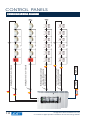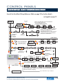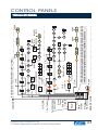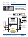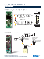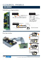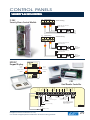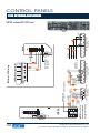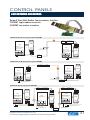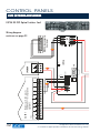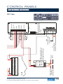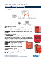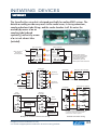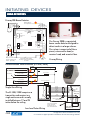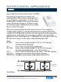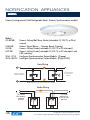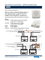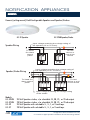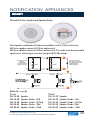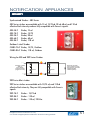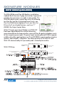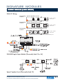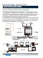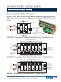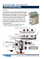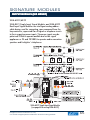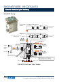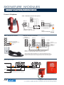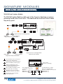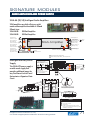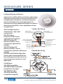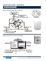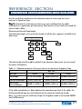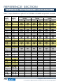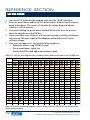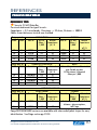
1
cro C tab ss-r able les efe Pa ren ge ce 95 TM EDWARDS SYSTEMS TECHNOLOGY INSTALLER’S WIRE GUIDE A CONCISE POCKET REFERENCE TO WIRE AND CABLE REQUIREMENTS FOR EST PRODUCTS AND SYSTEMS FIRE ALARM SECURITY ACCESS CONTROL CCTV Published by Edwards Systems Technology In conjunction with Paige Electric Co., L.P. EST CONTACTS Website United States Bradenton, FL www.est.net Fax 866-503-3996 Phone 888-378-2329 Canada Owen Sound, ON www.edwards.ca 519-372-2705 519-376-2430 International Toronto, Canada www.estinternational.com 905-270-9553 905-270-1711 Corporate Headquarters, EST 90 Fieldstone Court, Cheshire, CT U.S. Manufacturing, EST Pittsfield & Newport, ME Offices Worldwide Bradenton, Fl, USA • Cheshire, CT, USA • Pittsfield, ME, USA • Owen Sound, ON, Canada • Toronto, ON, Canada • London, UK • Santiago, Chile • Abu Dhabi, UAE • Dubai, UAE • Shanghai, China • Beijing, China • Singapore • New Delhi, India EDWARDS SYSTEMS TECHNOLOGY INSTALLER’S WIRE GUIDE A CONCISE POCKET REFERENCE TO WIRE AND CABLE REQUIREMENTS FOR EST PRODUCTS AND SYSTEMS FIRE ALARM SECURITY ACCESS CONTROL CCTV Published by Edwards Systems Technology In conjunction with Paige Electric Co., L.P. EST Installer ’s Wire Guide Installer’s Published by EST Press, an imprint of Edwards Systems Technology in conjunction with Paige Electric Co., L.P. Copyright © 2004 Edwards Systems Technology All rights reserved. 8985 Town Center Parkway, Bradenton, FL 34202 EST P/N P/N:: 85010-0139, Issue 2 ISBN ISBN:: 0-9706268-3-5 Wiring diagrams provided herein are for information and reference only and are not to be used for installation purposes. Consult the appropriate installation documents for wiring and configuration details. This guidebook is for information only and is not intended as a substitute for verbatim legislated requirements. For authoritative specifications regarding the application of life safety, security, and access control systems, consult current editions of applicable codes and standards. For authoritative interpretation of those codes and standards, consult your local authority having jurisdiction. While every effort has been made to ensure the accuracy and completeness of this guidebook, the authors and publishers assume no responsibility for errors, inaccuracies, omissions, or any inconsistencies herein. For more information or questions relating to fire alarm products shown in this guide, contact EST. For more information or questions relating to cable products shown in this guide, contact Paige Electric. Synergy, FullLight Strobe Technology, Genesis, and Signature Series are trademarks of Edwards Systems Technology Inc. Also from EST PPress: ress: Security and Access Control Handbook – A practical guide to application and system design Handbook of Visual Notification Appliances for FFire ire Alarm Applications – A practical guide to regulatory compliance Glossary of FFire ire Alarm and Security TTerminology erminology – A desk reference for life safety and security professionals INTRODUCTION This technical handbook has been designed to provide the users and installers of EST Systems with quick information in a condensed, user-friendly format. EST/Paige part numbers contained in this handbook have highlighted cable characteristics to allow you to easily identify the cable you require for each installation. Multiple charts and graphs detail technical data for wire and cable to assist you with calculations. If we can provide additonal technical support, answer any of your daily questions, or assist with your additional requirements, we invite you to contact our technical service hotline. TOLL FREE HOTLINE: 1-800-655-4497 It is our intention to keep the product information current and accurate. We can not cover specific applications or anticipate all requirements. All specifications are subject to change without notice. For more information or questions relating to fire alarm products shown in this guide, contact EST. For more information or questions relating to cable products shown in this guide, contact Paige Electric. Diagrams are for reference only. Consult the appropriate installation sheet for wiring details. TM 1 HOW TO USE THIS GUIDE This book is provided to assist system designers and installers in the selection of cables for use with EST products. Those unfamiliar with EST Products should start by selecting a control panel. The information shown for each control panel includes wiring diagrams and circuit tables. The circuit type is designated with a letter, (A-Z). In the tables, the letters are listed on the left, on the drawings, letters appear in red diamonds. Once the circuit type (A-Z) is identified, the user can proceed to the Paige Catalog included in this guide. Users familiar with EST products and their circuit types can proceed directly to the circuit type to obtain the cross reference. Keys to symbols used in the diagrams can be found on pages 12, 13 and 16. Triangle symbols on diagrams refer to notes on the relevant catalog sheets and technical manuals. Please consult these for further information. This book contains a wealth of reference information about cable selection and other related topics. This information can be found in the Reference Section. As always, your comments are welcome. Please let us know how we can improve this guide. For additional copies, contact: EST Marketing: By e-mail at: [email protected] By telephone: 888-378-2329 2 TM Diagrams are for reference only. Consult the appropriate installation sheet for wiring details. TABLE OF CONTENTS EST PRODUCTS Product Overview 6 Control Panels Fireshield 7 QuickStart 11 EST3 21 EST3 Network Annunciator 36 Envoy Graphic Annunciator 37 Fireworks 38 Booster Power Supplies 40 Conventional Initiating Devices Manual Stations: 270, 276, 277, 278, 279, 1534-1 41 Detectors: CSBU-1, EC30U-3, ED20FTU, EC20RRU-3, EC-LED, EC-DTS, 280 Series 42 SuperDuct 43 Beam Detectors 44 Notification Appliances Genesis (wall mount): Chimes, Chime-strobes: GC-HVDM 45 Genesis (ceiling mount): Horns, Strobes, Sync Modules: GC-HVDM 46 Genesis (wall mount): Speakers: G4-S2VM, G4-S7VM 47 Genesis (ceiling mount): Speakers: GC-S2VM, GC-S7VM 48 Integrity (ceiling mount): Speakers: 964, 965 49 Integrity (wall mount): Strobes: 405 Series 51 Integrity (wall mount): Speakers, Speaker / Strobes: 757 Series 52 Integrity: Horns, Horn-strobes: 757 Series 54 Hazardous Location Notification Appliances 55 Diagrams are for reference only. Consult the appropriate installation sheet for wiring details. TM 3 TABLE OF CONTENTS EST PRODUCTS (CONTINUED) Signature Modules Manual Pull Station w / Module: SIGA-270, -270P, -278, -271 56 Fire Input Modules (gang mount): SIGA-CT1, -CT2, -WTM, -MM1, -UM 57 Fire Input Modules (UIO mount): SIGA-UIO (2R, 6, 6R), -MCT1, -MCT2, -MAB 58 Security Input Modules: SIGA-SEC-2, -MD 59 Output Modules (gang mount): SIGA-CC1, -CC2, -UM, -CR, -CRR 60 Output Modules (UIO mount): SIGA-UIO (2/rm, 6, 6R), -MCC1, -MCC2 -MAB, -MCR, -MCRR 63 Firemen’s Telephone / Warden Station: SIGA-(M)CC1 68 Releasing Module: SIGA-REL 69 Isolator Module: SIGA-IM 70 Audio Amplifiers & Power Supply: SIGA-AA(30, 50), -APS(220) 71 Detectors Detectors: SIGA-IPHS (4), -PHS (3D), -PS, -IS, -HFS, -HRS, -LED, -DTS 72 Duct Detectors: SIGA-DMP, -DM 73 Detector Accessories: SIGA-LED, -DTS 74 Reference 24 Vdc NAC Wire Length 4 75 25 or 70 Vrms NAC Wire Length 78 Signature Data Circuit 80 Network Data Riser 87 3-SAC Data Bus & Power 89 Paige Wire Tables 95 TM Diagrams are for reference only. Consult the appropriate installation sheet for wiring details. TABLE OF CONTENTS LIST OF TABLES & REFERENCES Circuit Reference Table - Fireshield 9 Circuit Reference Table - QuickStart (QS1, QS4, QSC) 18 Circuit Reference Table - EST3 22 Table A-1: Wire resistance ratings to use for wire length calculations 75 24 Vdc NAC Voltage Drop calculations 76 24 Vdc NAC maximum wire length calculation 77 25 Vrms or 70 Vrms NAC wire length calculation 78 Table B-1: Maximum allowable length at 25 Vrms, 0.5 dB loss 79 Table B-2: Maximum allowable length at 70 Vrms, 0.5 dB loss 79 Signature data circuit maximum wire length calculations 80 Table C-1: Maximum amount of wire for constructing a Signature loop 81 Tables C-2 to C-5 show longest allowable circuit paths (configured for 2-wire smokes) Table C-2: 0 SIGA-UMs or SIGA-MABs 83 Table C-3: 1 to 5 SIGA-UMs or SIGA-MABs 84 Table C-4: 6 to 10 SIGA-UMs or SIGA-MABs 85 Table C-5: 11 to 15 SIGA-UMs or SIGA-MABs 86 Network data riser limits 87 3-SAC Data Bus & Power 89 Form A: 3-SAC alarm and standby load 90 Table D-1: SAC bus wire lengths versus number of doors and current loads using 16 AWG wire 91 Table D-2: SAC bus wire lengths versus number of doors and current loads using 14 AWG wire 93 Circuit Compatibility Matrix 94 Paige Wire Tables 95 Diagrams are for reference only. Consult the appropriate installation sheet for wiring details. TM 5 EST PRODUCT OVERVIEW Over a century ago when Robert Edwards installed the world’s first electric fire alarm bell in a New York City church, he began a tradition of innovation that would chart the course of building safety and security for the next 130 years. From pioneering work in multisensor technology, to award-winning design breakthroughs, the company that bears his name has established itself as the leader in cutting-edge systems and technology. Today, that name is synonymous with innovation and quality, and Edwards Systems Technology is widely regarded as the company that has achieved some of the most significant and forwardlooking advances in its field. Among EST’s innovations you’ll find: Signature Series: the world’s first truly intelligent multisensor smoke detector combines the output from three sensing elements and compares the results over time against sophisticated algorithms that characterize different types of combustion. Synergy Enabled EST3: the first multi-function network control platform to earn across-the-board listings for fire detection, security, and access control. EST peer-to-peer networking: an innovation that rendered much of the industry’s master/slave networks obsolete virtually overnight. Genesis Series: the world’s smallest and slimmest line of audible and visual notification appliances eliminates bulky specular reflectors used in other emergency strobes and adds design appeal. In this guide you will find EST products organized into the following subsections: • Control Panels, FireWorks and Booster Power Supplies • Initiating Devices: Manual Stations, EC Detectors and other detectors • Notification Appliances • Signature Analog Addressable Devices • Accessories 6 TM Diagrams are for reference only. Consult the appropriate installation sheet for wiring details. CONTROL PANELS FIRESHIELD The FireShield family of conventional panels and accessories consists of three panels, a DACT/dialer, serial remote annunciators and relays, city tie modules and reverse polarity modules. FireShield’s ingenious initiating device circuits (IDCs) can be programmed for one of eight configurations. Several of these configurations allow the use of one zone to do the work of two. Verified detection circuits allow detectors and contact devices (such as pull stations) to be installed on the same zone. Combination circuits allow waterflow switches and their associated valve tamper switches to be connected on a common two-wire IDC. FireShield panels are available in three sizes and can be ordered with or without the optional DACT: FS302 – The three-zone FS302 is ideal for use as a sprinkler supervisory panel. It includes three Class B IDCs and two Class B NACs. FS502 – Factory configured with five Class B IDCs and two Class B NACs. FS1004 – Factory configured with 10 Class B IDCs and four Class B NACs. On the FS502 and FS104, IDCs or NACs can be paired to form single Class A circuits. All panels are available in a red or gray finish. Following Page: The optional DACT/Dialer is a multifunction module that provides communications, modem capability, and LCD display functions. Its primary function is as a Digital Alarm Communicator Transmitter (DACT). The FSRSI is ideal for common system annunciation. It includes five LEDs and a local silence/lamp test switch. The FSRZI-A is used to indicate zones in the alarm state. It contains five red LEDs. The panel can support two modules programmed for each selection. The Remote Relay Module (FSRRM) can be configured to function in either a zone relay mode or a common system mode. Diagrams are for reference only. Consult the appropriate installation sheet for wiring details. TM 7 CONTROL PANELS FIRESHIELD FSRSI (Remote System Indicator) DACT (Digital Alarm Communicator Transmitter) R RJ31 jacks FSRZI-A (Remote Zone Indicator) To wall phone jack Line 1 Line 2 Phone cables (supplied) RJ31 jacks -24V +24V C+ C- TB1 TB2 LINE IN GROUP J2 #1 IN #2 OUT From control panel or previous device { J2 LINE OUT Communication in Communication in + Power in + Power in - 24V IN C IN - + + 24V OUT C OUT - + + - I { Power out + Power out - V Communication out Communication out + To next device FSRRM (Remote Relay Module) { From control panel or previous device To next device Communication out - Communication in + Communication out + Communication in - Power in Power in + V I V { N OUT 1 24V IN C IN C OUT OUT 3 + - - + - + NO C NC NO C NC N N 24V OUT + - X OUT 2 OUT 5 OUT 4 NO C NC NO C NC NO C NC I Power out Power out + { To next device 8 TM Diagrams are for reference only. Consult the appropriate installation sheet for wiring details. Diagrams are for reference only. Consult the appropriate installation sheet for wiring details. Wiring for the FSRSI, FSRZI-A or FSRRM. Plug to plug cable For cable part numbers turn to the Paige / EST Cross Reference Table on the page indicated. For maximum wire lengths see the tables, formulas and matrix in the reference section. For more detail on wiring specifications refer to the product manuals and installation sheets for the specific product. FPL, FPLR, FPLP 18 AWG to 12AWG Serial Communication Bus for remote annunciator & relays 99 V 7 ft long cable supplied with FSDACT - R Five dry contact relays. Form C configurable as zone or common TFN, THHN, FPL, FPLR, FPLP Telephone Line - DACT connection to RJ31X jack 95 N Power for 4 Wire Detector, Relay, FSRSI, FSRZI-A, FSRRM. AWG depends on voltage drop TFN, THHN, FPL, FPLR, FPLP 18 AWG to 12 AWG 18 AWG to 12AWG 24 VDC Power distribution (Aux) 95 I Horns & Strobe circuits Alarm, Waterflow, Supervisory & Monitor circuits TFN, THHN, FPL, FPLR, FPLP TFN, THHN, FPL, FPLR, FPLP Notes Description Relay Module (FSRRM) 18 AWG to 12AWG Notification Appliance Circuit (NAC) 24 VDC 95 B Gauges 18 AWG to 12AWG Circuit Type Initiating Device Circuit (IDC) 95 A Ref/Pg Circuit Reference Table - FireShield CONTROL PANELS CIRCUIT REFERENCE TABLE - FIRESHIELD TM 9 10 TM A V I and A A FSRSI B B FSRRM B Notification Appliance Circuit – Class A with Combination Horn-Strobe Circuit Notification Appliance Circuit – Class B with Combination Horn-Strobe Circuit Initiating Device Circuit – Class B Initiating Device Circuit – Class A 1 Pr. 1 Pr. 1 Pr. 1 Pr. CONTROL PANELS FIRESHIELD WIRING DIAGRAM Diagrams are for reference only. Consult the appropriate installation sheet for wiring details. CONTROL PANELS QUICKSTART QSC EST’s QSC life safety control panel provides a cost-effective solution for larger conventional life safety applications. Supporting up to 48 conventional Class B or a combination of 40 Class A and Class B initiating circuits, this panel leaves plenty of room to grow. QSC is compatible with either two- or four-wire conventional detectors. QuickStart’s modular design brings flexibility to every installation. Option cards provide a dialer, auxiliary relays and additional system capacity. QSC also supports as many as eight remote annunciators and up to 60 programmable front panel switches with dual LEDs for system control and display. Diagrams are for reference only. Consult the appropriate installation sheet for wiring details. TM 11 CONTROL PANELS QUICKSTART QSC CONVENTIONAL CIRCUIT OPTIONS Consult the QuickStart Wiring Reference Table on page 18 for further details. A Initiating Device Circuit – Class A A F 1 Pr. Initiating Device Circuit – Class B A F Class B Notification Appliance Circuit with Genesis Signals and Signal Master for independent horn and strobe control and synchronization. 1 Pr. B G M G G 2 Pr. B G I I 1 Pr. Notification Appliance Circuit – Class B with Separate Strobe and Horn Circuits Optional LED/Switch Card G I I Optional LED/Switch Card 2 Pr. B Notification Appliance Circuit – Class A with Combination Horn-Strobe Circuit I I QSC Panel I I 1 Pr. I and U Up to eight annunciators per panel – Class A or Class B wiring. Second through eighth annunciator must be powered from a Booster Power Supply. S PT-1S Printer 2 pr. Class B or 4 pr. Class A Legend G 12 Genesis Horn-Strobe I TM Enhanced Integrity Horn-Strobe F Manual Pull Station G M Genesis Signal Master Smoke Detector Diagrams are for reference only. Consult the appropriate installation sheet for wiring details. CONTROL PANELS QUICKSTART QS1 EST’s QS1 life safety control panel brings big-system intelligent control to small applications. Supporting up to 250 intelligent detectors and modules, QS1 takes full advantage of EST’s exclusive Signature Series technology, which provides electronic addressing, automatic device mapping, environmental compensation, and true multisensor detection. QuickStart’s innovative design makes it easy to add a dialer or extra auxiliary relays. QS1 also supports as many as eight remote annunciators and up to 30 programmable front panel switches with dual LEDs for system control and display. The benefits brought by QS1 to retrofit applications underscore the true potential of this powerful system. As an intelligent panel, QS1 supports Signature Series devices, which can use existing wiring in most retrofit applications. This makes upgrading from a conventional system to analog control a simple operation with minimal disruption to normal operations at the site. Legend for diagrams on pages 14 & 15 I Enhanced Integrity Horn-Strobe G Genesis Horn-Strobe G M Genesis Signal Master Smoke Detector R I 2 F Smoke Detector with Relay Base Smoke Detector with Isolator Base IO End-of-Line Resistor CR Control Relay Module Programmable I/O Module CC1 Signal Module RM Riser Monitor Module 2-Wire Smoke Detector UM Universal I/O Module Manual Pull Station CT2 Dual Circuit Input Module Diagrams are for reference only. Consult the appropriate installation sheet for wiring details. MM1 J Monitor Module Junction Box TM 13 CONTROL PANELS QUICKSTART QS1 CLASS A SIGNATURE DATA CIRCUIT Consult the QuickStart Wiring Reference Table on page 18 for further details. g see legend on page 13 RM 1 Pr. UM I J D G M 1 Pr. 1 Pr. CR G G G G B Class A Notification Appliance Circuit with Genesis Signals and Signal Master for Independent Horn and Strobe Control and Synchronization over two conductors. J J D I F R Class A Signature Data Circuit Fire Damper I 2nd Floor 1 Pr. B B I J Class B Notification Appliance Circuit CC1 I I I 2 Pr. CC1 J J A IO I U Critical Process 24 Vdc Monitoring 1 Pr. with Control B I U I & J J F A Switch Waterflow F I 2 Pr. CT2 A Sprinkler Supervisory Switch I CR Elevator Class A Capture Notification Appliance Circuit U CR QS1 Panel Up to eight annunciators per panel – Class A or Class B wiring. Second through eighth annunciator must be powered from a Booster power supply S PT-1S Printer 14 TM 2 pr. Class B or 4 pr. Class A Diagrams are for reference only. Consult the appropriate installation sheet for wiring details. CONTROL PANELS QUICKSTART QS1 CLASS B SIGNATURE DATA CIRCUIT Consult the QuickStart Wiring Reference Table on page 18 for further details. see legend on page 13 RM 24 Vdc 1 Pr. CR CC1 2 Pr. J B B Horn and Strobe Synchronization with Audible Silence 1 Pr. G M G G G 2 Pr. J Fire Damper Data Circuit (1 pr.) 2nd Floor 1 Pr. B B J J I D Horn and Strobe Control (2 pr) MM1 I 24 Vdc 1 Pr. F J R D Signature G Class B Notification Appliance Circuit with Genesis Signals and Signal Master for Independent Horn and Strobe Control and Synchronization over two conductors. A Critical Process Monitoring B CC1 B CC1 G F CT2 G G U I & S A A G Notification Appliance Circuit: Horn and Strobe Synchronization with Audible Silence QS1 Panel I F J 1 Pr. G M I 2 Pr. J 2 Pr. B I Waterflow Switch Sprinkler Supervisory Switch N CR Elevator Capture CR Up to eight annunciators per panel – Class A or Class B wiring. Second through eighth annunciator must be powered from a Booster Power Supply. PT-1S Printer Diagrams are for reference only. Consult the appropriate installation sheet for wiring details. 2 pr. Class B or 4 pr. Class A TM 15 CONTROL PANELS QUICKSTART QS4 EST’s QS4 QuickStart life safety control panel provides conventional and intelligent addressable circuits in a single intelligent control panel. Supporting up to 1,000 intelligent detectors and modules, QS4 takes full advantage of EST’s exclusive Signature Series technology, which provides electronic addressing, automatic device mapping, environmental compensation, and true multisensor detection. As a hybrid system, QS4 combines support for four Signature addressable circuits (1000 addressable points) along with up to 48 conventional Class B or a combination of 40 Class A and Class B initiating circuits. Compatible with either two- or four-wire detectors, conventional detectors. QuickStart’s design leaves plenty of room for system expansion. Option cards include a dialer, auxiliary relays, and additional system capacity. The QS4 also supports as many as eight remote annunciators and up to 60 programmable front panel switches with dual LEDs for system control and display. Legend for diagram on page 17 I Enhanced Integrity Horn-Strobe G Genesis Horn-Strobe G M Genesis Signal Master I 2 F Smoke Detector 16 R TM Smoke Detector with Relay Base Smoke Detector with Isolator Base IO End-of-Line Resistor CR Control Relay Module Programmable I/O Module CC1 Signal Module RM Riser Monitor Module 2-Wire Smoke Detector UM Universal I/O Module Manual Pull Station CT2 Dual Circuit Input Module MM1 J Monitor Module Junction Box Diagrams are for reference only. Consult the appropriate installation sheet for wiring details. CONTROL PANELS QUICKSTART WIRING DIAGRAM see legend on page 16 RM 24 Vdc 1 Pr. 1 Pr. I G M 1 Pr. Class A Signature Data Loop 1 Class A Notification Appliance Circuit with Genesis Signals & Signal Master for Independent Horn & Strobe Control and Synchronization over two conductors. B UM J G G G G CR I F R Fire Damper D I Signature Data Loop 2 (optional) IO D D D D Signature Data Loop 3 (optional) Signature Data Loop 4 (optional) J F J J Critical Process Monitoring with Control F A A G M G G G A A F 2 2 2 2 2 1 Pr. Initiating Device Circuit – Class B A F 2 Class B Notification Appliance Circuit with Genesis Signals & Signal Master for Independent Horn & Strobe Control and Synchronization over two conductors. B G M 1 Pr. G Notification Appliance Circuit – Class A with Combination Horn-Strobe Circuit QS4 Panel PT-1S Printer 2 pr. Class B or 4 pr. Class A U I & G G I G 1 Pr. B 2 Pr. S G 1 Pr. Class B Notification Appliance Circuit with Genesis Signals & Signal Master for Independent Horn & Strobe Control and Synchronization over 2 conductors. I CR 24 Vdc 1 Pr. 1 Pr. Initiating Device Circuit – Class A Elevator Capture Sprinkler Supervisory Switch B CR CC1 CR Waterflow Switch CT2 I I I 1 Pr. Up to eight annunciators per panel – Class A or Class B wiring. Second through eighth annunciator must be powered from a Booster Power Supply. Diagrams are for reference only. Consult the appropriate installation sheet for wiring details. TM 17 For cable part numbers turn to the Paige/EST Cross Reference Table on the page indicated Ref/Pg Circuit Type Gauges Description Notes Initiating Device Circuit TFN, THHN, FPL, FPLR, Input circuits on ZB16-4, ZA8-2 and A 95 18 AWG to 12 AWG (IDC) FPLP modules (CT1, CT2, WTM, MM, UM & MAB) Notification Appliance TFN, THHN, FPL, FPLR, Output Circuits on SLIC, ZB16-4, ZA8-2, B 95 18 AWG to 12 AWG Circuit (NAC) 24 Vdc FPLP and modules (CC1, CC2, UM, & MAB) TFN, THHN, FPL, FPLR, Loop Controller (SLIC) card to D 95 Signature Addressable Loop 18 AWG to 12 AWG FPLP addressable devices 24 Vdc Power distribution TFN, THHN, FPL, FPLR, 4 Wire Detector/Relay/Annc. I 95 18 AWG to 12 AWG (Smoke Acc. & AUX Power) FPLP AWG depends on voltage drop TFN, THHN, FPL, FPLR, Eight dry contact relays (ZR8) N 95 Relay Module (ZR8) 18 AWG to 12 AWG FPLP Form A or B configurable. Telephone Line - DACT R 7 ft cable supplied with FSDACT supplied with DACT Terminal to Plug cable connection to RJ31X jack RS-232 Communications S 99 18 AWG 4 cond. min. FPL, FPLR, FPLP 50 Ft Max. Panel to Printer (Printer Wiring) Communications Annunciator to Panel and Network U 98 18 AWG to 12 AWG FPL, FPLR, FPLP Network RS-485 Annunciator For maximum wire lengths see the tables, formulas and matrix in the reference section. For more detail on wiring specifications refer to the product manuals and installation sheets for the specific product. CONTROL PANELS CIRCUIT REFERENCE TABLE - QUICKSTART (QS1, QS4, QSC) 18 TM Diagrams are for reference only. Consult the appropriate installation sheet for wiring details. CONTROL PANELS QUICKSTART OPTION CARDS NT-A Class A RS-485 Card/UART Port U CH2 ZR8 Relay Card N N CH2 RA RA CH1 CH1 TB1 U +R1– +R2– +R3– +R4– +R5– +R6– +R7– +R8– TB2 TB1 + – + – CH2 CH1 N N N N N N ZB16-4 Class B Zone Card Z10 Z11 Z12 Z13 Z14 Z15 Z16 R1 R2 TB1 A A TB2 B Z1 Z2 Z3 Z4 Z5 Z6 Z7 Z8 OUT + – Z9 IN + LOOP – A+ A– B+ B– TB2 D SLIC Signature Loop Intelligent Controller CI Class A ZA8-2 Class A Zone Card TB1 A B A ZONE 1 B A ZONE 2 B A ZONE 3 B EOLR B A IN ZONE 4 NACPWR Diagrams are for reference only. Consult the appropriate installation sheet for wiring details. ZONE 5 B A ZONE 6 B A ZONE 7 B A A TB2 ZONE 8 NACPWR B A IN EOLR B TM 19 CONTROL PANELS QUICKSTART OPTION CARDS AND ACCESSORIES SURGE PROTECTOR RING (RED) DLD Dual Line Dialer RJ31X 8 PIN MODULAR CONNECTOR FOR PHONE LINE #1 4 3 2 1 5 TIP (GREEN) 6 TO PHONE LINE #2 (WIRED SAME AS PHONE LINE #1) 7 GREEN 8 4 3 2 RED R NO T-TAPS PERMITTED PREMISES PHONES 5 6 7 1 RJ31X 8 PIN MODULAR CONNECTOR FOR PHONE LINE #2 8 R TB1 TIP RNG TIP RNG TIP RNG TIP RNG IN OUT IN OUT LINE 1 LINE 2 2-CTM City Tie Module 24 to Vdc Riser out next device Power riser out or EOL Relay Riser in 24 Vdc from EST2 Power riser Panel out Data in I Alarm/Supervisory Wiring A SIGA-CC1 /MCC1 Master Box 2-CTM D Municipal Circuit Data out PT-1S Serial Printer TB1 I 24V+ 24V- 1 2 3 S COM 5 6 JB1 3 2 1 UP RX 4 SW1 TX PS6 TB1–18 TO PT–1S 7 32 S S TB3 COM–COM TM RxD–TxD TxD–RxD 1 2 3 4 JB2 20 PS6 TB1–17 PS6 TB1–16 IOP3A JB3 DB–25P REAR VIEW JB4 (see page 24 for 9-pin wiring) TB2 S S COM–COM 7 TX–RX 3 2 RX–TX TO PT–1S DB–25P REAR VIEW Other Accessories: CDR-3 Coder (for wiring diagram see page 33) RPM Reverse Polarity Card (no wiring diagram available) Diagrams are for reference only. Consult the appropriate installation sheet for wiring details. CONTROL PANELS EST3 EST3 is a modular system uniquely designed to easily meet the needs of standalone single node systems or multimode networks. Fire alarm, security, access control and audio functions use the same fundamental components, simplifying system layouts. EST3 is a superbly adaptable life safety system, lending itself to medium and large building applications. Cabinets are available with room for system batteries up to 65 Amp hours. With EST3, one 24-volt battery supports up to four power supplies. Each supply will support up to 7 Amp load. With four supplies, 28 Amps of current is available — all backed up by a common battery. EST3 operates on a multi priority peer-to-peer token ring network. The multi-priority token ring gives EST3 exceptional response. EST3 token ring network configuration also permits vast distances between nodes. The allowable distance between nodes on #18 AWG (0.75mm2) is 5,000 ft (1,523 m). With 64 nodes supported on a network, the total network length is in excess of 300,000 ft (91,400 m), or nearly 60 miles! A single node supports up to 10 Signature loop controllers with 250 devices per loop, (2,500 points total per node, 160,000 points per network). Taking full advantage of digital technology, up to eight channels of audio sources can be sent over a single twisted pair of wires between nodes. Coupling the inherent reliability and performance of zoned amplifiers with EST3 simplified user interfaces makes audio system design and operation both easy and dependable. EST3 is the right choice for any medium to large application. Its multiplex functions are second to none in the industry today. Diagrams are for reference only. Consult the appropriate installation sheet for wiring details. TM 21 22 Initiating Device Circuit (IDC) 95 95 95 95 95 96 95 97 96 96 95 A B C D E H I K L M N TM 18 AWG to 12 AWG 18 AWG to 12 AWG 18 AWG to 12 AWG 18 AWG to 12 AWG 18 AWGt o 12 AWG 18 AWG to 12 AWG 18 AWG to 14 AWG 22 AWG to 16 AWG 22 AWG to 16 AWG 18 AWG to 12 AWG 18 AWG to 12 AWG Gauges Notes Input circuits on 3-IDC8/4 and modules (CT1, CT2, WTM, MM, UM & MAB) Output Circuits on ZA8-2 and modules TFN/THHN, FPLR, FPL, FPLP (CC1, CC2, UM, & MAB) Twisted Pair - FPLR, FPL, FPLP 3-ZAxx to CC1 & CC2 & speakers TFN/THHN, FPLR, FPL, FPLP Loop Controller (3-SSDC) to Signature devices. TFN/THHN, FPLR, FPL, FPLP 3-AADC to Addressable devices (not Signature) 1 Pair Twisted Shielded 3-ASU to CC1, CC1 to Jack/Station. TFN/THHN, FPLR, FPL, FPLP 4 Wire Detector/Relay/Annc. AWG depends on voltage drop FPLR, FPL, FPLP 3-SAC to CRC & KPDISP. FPLR, FPL, FPLP or CM, CMR, CMP CRC to Card/PIN Reader. FPLR, FPL, FPLP or CM, CMR, CMP CRC or SEC-2 to Door Contact/ Request to Exit. Five dry contact relays. TFN/THHN, FPL, FPLR, FPLP Form C Configurable as zone or common 3-Modcom to RJ31X, 7 feet, plug to plug, Supplied with 3-Modcom cable EST P/N 3601377. 50 feet Max. Panel to Printer or from Panel FPLR, FPL, FPLP or CM, CMR, CMP to Fireworks FPLR FPL, FPLP 5000 feet max between any three panels. FPLR, FPL, FPLP 5000 feet max between any 3 panels. TFN/THHN, FPLR, FPL, FPLP Description R - CO Telephone Line Supplied with 3-Modcom RS-232Communications 22 or 18 AWG S 99 Printer/Fireworks 4 cond. min. T 98 Audio Network 18 AWG to 12 AWG U 98 RS-485 Communications Network 18 AWG to 12 AWG 9/125 Singlemode 62.5/125 mm or W 100 Network Fiber Optics OFNR, OFNP Fiber Optic (3-FIB) card 100/140 mm Multimode X 100 Netcom-16D Router Cable (Ethernet) CAT 5E/6 CMR, CMP, CMG. CM Cable from Fireworks to NETCOM-16D (300Ft. Max) Fireworks Short Haul Modems 26 AWG Min. Twisted Pairs Cable for Modem to Modem connections Y 100 (FW-XPC/FW-XPL) (4 Conductor) Telephone cable (FW-XPC/FW-XPL) For maximum wire lengths consult the reference section. For more detail on wiring specifications refer to the product manuals and installation sheets for the specific product. Relay Module (FSRRM) Notification Appliance Circuit (NAC) 24 Vdc Notification Appliance (NAC) Audio Signature Analog Addressable Loop Analog Addressable Loop Firemen's Telephone 24 Vdc Power distribution Security (3-SAC) Bus Card/PIN Reader Security Device Circuit Circuit Type Ref/Pg CONTROL PANELS CIRCUIT REFERENCE TABLE - EST3 For cable part numbers turn to the Paige/EST Cross Reference Tables on the pages indicated below. Diagrams are for reference only. Consult the appropriate installation sheet for wiring details. Diagrams are for reference only. Consult the appropriate installation sheet for wiring details. TM EDWARDS SYSTEMS TECHNOLOGY GROUND FLOOR Primary Power Source Paging Company TELCO Access Control Data Base (ACDB) Central Monitoring Station (CMS) 1 Pr & 2 Tw/Sh Pr. S I SEC F MD J KPDISP F MD CRC DOOR J SEC SECURITY INPUTS J MM F WATER LEVEL MONITOR CRC DOOR F F DOOR CRC PRINTER CPU w/display, power supply & booster,dual loop module, audio source module w/master firefighter's telephone, 2 amplifiers, & batteries K J J 2 Pr. FIRE DAMPER SECURITY INPUTS H 1 Tw/Sh Pr. 2 Tw. Pr. CC 1 Pr. & 2 Tw/Sh Pr. C D 1 Pr. 2 Pr. 1 Tw/Sh Pr. S CC HVAC MONITOR MM S 1st FLOOR HVAC CONTROL J S CR S S 1 Pr. S 2 Pr. S R S S J S S 2 Pr. KPDISP S S S I CRC DOOR S S S S S S 2 Tw. Pr. S S S S S S S To next Network Node (EST3 Remote Floor Panel) S S 2nd FLOOR CONTROL PANELS TYPICAL EST3 WIRING 23 CONTROL PANELS EST3 NETWORK 3-CPU1 Central Processor Unit Module As a single node standalone system, the 3-CPU1 can control up to 19 local rail modules. For larger systems, up to 64 nodes interconnect on a peer-to-peer multi-priority token ring protocol network. Communications Cards (mount to back of module) 3-RS232: Two optically-isolated RS-232 ports support connection of a printer and/or an external command center. 3-RS485A/B: The 3-RS485A card provides a Class A or Class B circuit for network communications signal and two additional circuits for Class A digitized audio signals. The 3RS485B card provides one Class B circuit for network communications and one for the digitized audio signals. From next panel 3-CPU1 Module N.O. SUPV. COM SUPV. SYSTEM SUPERVISORY RELAY N.C. SUPV. 7 8 9 N.O. ALARM COM ALARM SYSTEM ALARM RELAY N.C. ALARM COM. TROUBLE N.O. TROUBLE N.C. TROUBLE 3 4 5 6 10 Connect to TB2 on 3-CPU1 Module 19 18 17 16 15 14 13 12 11 10 T 9 8 7 6 5 4 3 2 1 DB9 FEMALE (REAR VIEW) S S S S PIN 9 (5) COM (3) TXD PORT #2(isolated) TO PRINTER OR REMOTE COMMAND SYSTEM, (2) RXD T PIN 1 OR PIN FUNCTION U U PLUG PIN # Network Data Riser 2 CENTRAL PROCESSING UNIT MODULE 20 T 1 3-CPU1 Connect to TB1 on 3-CPU1 Module Network Audio Riser Class A only To/From next panel 3-CPU1 Module SYSTEM TROUBLE RELAY (shown in normal state) COMMON SYSTEM RELAYS DB25 FEMALE (REAR VIEW) PIN 13 PIN 25 Network Audio Riser PORT #2(isolated) TO PRINTER OR REMOTE COMMAND SYSTEM, (7) COM 24 To previous panel 3-CPU1 Module or a 3-ASU To/From previous panel 3-CPU1 or a 3-ASU Class A only S S S (3) RXD (2) TXD PIN 14 PIN 1 PIN 13 PIN 25 DB25 FEMALE (REAR VIEW) PORT #1 ISOLATED PORT TO PRINTER OR REMOTE COMMAND SYSTEM. (7) COM (3) RXD (2) TXD PIN 14 PIN 1 TM Diagrams are for reference only. Consult the appropriate installation sheet for wiring details. CONTROL PANELS EST3 NETWORK AUDIO The Audio Source Unit (3-ASU/3-ASUFT) converts analog signals to digital signals. These units support connection of a local microphone, remote microphone, telephone voice line, and auxiliary audio input. H ULI/ULC Listed 47K ohm EOL Resistor H Typical Fire Fighter's Telephone Circuit 10 9 Twisted Shielded Pair if run with other wiring SIGA-CC1 8 7 6 5 4 3 2 1 COMMON SYSTEM RELAYS To Signature Data Circuit 1 2 3 4 5 6 7 8 9 10 To Phones Connect to TB1 on 3-CPU Module 10 9 3-CPU SIGA-CC1 8 7 6 5 To next panel 3-CPU Module H Network Audio Riser Network Data Riser Connect to TB2 on 3-CPU Module 20 19 18 17 16 15 14 13 12 11 10 9 8 7 6 5 4 3 2 1 H H T T U U U 4 3 2 1 MAIN PROCESSOR MODULE To Signature Data Circuit Telephone Riser Twisted Shielded Pair Connect Shield to Earth Ground only at the panel. Maintain shield continuity. Dashed Wires Required for Class 'A' Wiring Only 3-ASU or 3-ASUFT Audio Source Unit U From previous panel 3-CPU Module EST3 Diagrams are for reference only. Consult the appropriate installation sheet for wiring details. TM 25 CONTROL PANELS SIGNATURE DRIVER CONTROLLER MODULES The 3-SSDC and 3-SDDC Signature Driver Controller modules provide an intelligent interface between the 3-CPU(1) module and Signature Series fire alarm and security devices. 3-SSDC Single Signature Driver Controller Module (supports one Signature Data circuit) 3-SDDC Signature Dual Driver Controller Module (supports two Signature circuits) 3-SDC Signature Device Card (upgrades a 3-SSDC to a 3-SDDC) Signature Fire/Security I/O Modules Signature Fire/Security Detectors EST EST EST D I Typical Class B Wiring 1 2 3 4 5 6 SDC #1 Smoke Power 7 8 9 10 3-SDDC Signature Fire/Security I/O Modules D Typical Class A Wiring EST EST EST EST EST EST D Signature Fire/Security Detectors SDC #1 Smoke Power + + 1 2 3 4 5 6 7 8 9 10 3-SDDC 26 TM Diagrams are for reference only. Consult the appropriate installation sheet for wiring details. CONTROL PANELS 1 A 1 4 2 3 4 5 6 IDC #4 IDC #3 IDC/NAC #2 IDC/NAC #1 3-IDC8/4 Initiating Device Circuit (Hardwired) Module 7 8 NAC IN 1/2 EST3 MODULES 9 10 To TB1 on Module EOL 2 3 A TB1 Detector Base Detector Base RX TX JP1 JP2 3 2 1 INITIATING DEVICE CIRCUIT (IDC) 3 2 1 Connect to IDC 3, 4, 5, or 6 IDC/NAC 1, 2, 7, or 8 1 1 2 2 3 3 JP3 JP4 + + + + + TB2 EOL NOTIFICATION APPLIANCE CIRCUIT (NAC) 10 9 8 7 6 5 4 3 2 1 3-MODCOM Modem Communicator 4 3 PREMISES PHONES IDC #5 NAC IN 7/8 IDC/NAC #7 SURGE PROTECTOR RING (RED) YELLOW BLACK IDC #6 Connect to IDC/NAC 1, 2, 7, or 8 IDC/NAC #8 B B + 2 1 5 6 7 8 TIP (GREEN) RJ31X 8 PIN MODULAR CONNECTOR FOR PHONE LINE #1 TO PHONE LINE #2 (WIRED SAME AS PHONE LINE #1) 4 3 2 R 1 5 6 7 RJ31X 8 PIN MODULAR CONNECTOR FOR PHONE LINE #2 8 R 7 Ft. (2.13 M) LINE 1 LINE 2 MODCOM (front view) Diagrams are for reference only. Consult the appropriate installation sheet for wiring details. TM 27 CONTROL PANELS EST3 MODULES 3-OPS Off Premise Signaling Module 10 9 8 7 6 5 4 3 2 10 1 B B (+) 9 8 7 6 5 4 3 2 1 TROUBLE RELAY TERMINALS 1 & 2 (+) ALARM ALARM Polarity Reverses TROUBLE Power off ALARM has priority (+) ‘Old’ style reverse polarity operation (+) TROUBLE SUPERVISORY ‘New’ style reverse polarity operation 10 9 8 7 6 5 4 3 2 1 TROUBLE RELAY TERMINALS 1 & 2 B B MASTER BOX (+) City Tie Connection Note: Trouble relay contacts are configurable for N.O or N.C MUNICIPAL CIRCUIT Fiber Optics Interface P6 P8 P1 P3 W P5 P2 Fiber Optic Network Data Riser 14 dB - approx 8,000ft (2,400M) Between Panels Max. W P6 P8 P1 P3 P5 P2 W P6 P8 P1 P3 P5 W P2 Fiber Optic Network Data Riser 14 dB - approx 8,000ft (2,400M) Between Panels Max. P6 P8 P1 P3 P5 P2 28 TM Diagrams are for reference only. Consult the appropriate installation sheet for wiring details. CONTROL PANELS SECURITY & ACCESS CONTROL 3-SAC Security/Access Control Module 3-SAC Module TB2 A B RS-485 Ground RS-485 + G G + Not used Class A wiring Not used 10 1 K K From 24 Vdc circuit or local 120 Vac KPDISP Keypad CRC 3-SAC Module TB2 A B RS-485 Ground RS-485 + G G + Not used Class B wiring Not used 10 CRC 1 K K From 24 Vdc circuit or local 120 Vac KPDISP Keypad CRC CRC 120 W Terminating Resistor CRC 120 W Terminating Resistor From 24 Vdc circuit or local 120 Vac KPDISP Keypad CRC KPDISP Keypad Display 24 Vdc supply + – From last device RS-485 line + – POWER – + I I K K + – 24 Vdc supply To next device + – RS-485 line – + DATA Dry contact connections TB-2 + RS-485 OUT - RS-485 OUT Loop 2 IN Loop GND Loop 1 IN - RS-485 IN LED B Data 0 Sounder 10 11 12 13 14 15 16 17 18 19 20 21 22 23 + RS-485 IN 9 Reader GND 8 Data 1 7 LED A 6 C 5 Reader PWR NO 4 NC 3 1 -24 V OUT 2 2 16.5 Vac IN Strike PWR 1 16.5 Vac IN Strike GND +24 V IN +24 V OUT TB-1 J1 -24 V IN CRC Card Reader Controller Reader wire connections From Strike/maglock To next CRC or other device From power supply From 3-SAC module or previous CRC 47 K 47 K EOL EOL To next CRC or 120 W EOL if this is the last device on Class B or back to 3-SAC module if Class A. S1 From plug-in transformer Red (+) To battery Black (-) Diagrams are for reference only. Consult the appropriate installation sheet for wiring details. TM 29 TB1 1 TM 2 3 + - SUPV 24VDC OUT COM 30 4 RS232 IN 5 RXD TXD IN OUT 6 JB1 3 2 1 UP SW1 PROGRAM JB4 1 JB2 JB3 1 S 2 3 2 3 SUPVCOMTXD RXD RS232 #1 OUT 4 TB2 TB3 4 SUPVCOMTXD RXD RS232 #2 OUT DOWNLOAD CONFIGURATION DB-9 FEMALE PIN 1 7 8 DOWNLOAD CONFIGURATION DB-25 FEMALE 2 3 4 5 JUMPER 4-5 JUMPER 6, 8, 20 7 S 3 2 PRINTER CONFIGURATION DB-25 MALE 20 3 2 1 PIN 1 S S JB1 NOTE: The IOP3A must be configured in supervision mode. RED RED WHITE GREEN BLACK PROGRAM S GREEN BLACK RXD TXD IN OUT Switch shown in UP position. IOP3A UP SW1 RED WHITE C O M 2 6 S S S S R T S 2 + - SUPV 24VDC OUT 5 BLACK T X 2 S 24 Vdc I S S R X 2 4 WHITE C O M 1 3 GREEN R T S 1 2 JUMPER 7-8 JUMPER 1,4,6 S JB2 INSTALLED (PROVIDES 12V TO POWER MODEM) T X 1 1 IOP3A TB2 R X 1 3-CPU1 Panel controller TB1 COM IOP3A to 3-CPU1 wiring PIN 1 CONTROL PANELS EST3 NETWORK ACCESSORIES IOP3A Isolated RS-232 Card Diagrams are for reference only. Consult the appropriate installation sheet for wiring details. CONTROL PANELS EST3 NETWORK ACCESSORIES Network Short Haul Modem Communications Interface 3-NSHM1 single modem connection 3-NSHM2 two modem connection Network B to A wiring using the NSHM1 U Network A Side Ribbon Cable CPUx Note: No wiring permitted to Network B IN connection. Surge Protector Ground Fault Detector (GFD) NSHM1 CPUx Network B Side Up to 6 miles (see Specifications) TB2 Network OUT IN A A B B + - + - Network A Side Note: No wiring permitted to Network A OUT connection. Ribbon Cable TB2 Network OUT IN A A B B + - + - From previous panel controller TB2-NETWORK IN B+/B- NSHM1 Network B Side Surge Protector To next panel controller TB2-NETWORK IN A+/A- Network A to B wiring using the NSHM1 Ground Fault Detector (GFD) Surge Protector Network A Side U CPUx Note: No wiring permitted to Network A OUT connection. Note: No wiring permitted to Network B IN connection. Network A Side Ribbon Cable TB2 Network OUT IN A A B B + - + - Ribbon Cable CPUx TB2 Network OUT IN A A B B + - + - NSHM1 Network B Side Up to 6 miles (see Specifications) From previous panel controller TB2-NETWORK IN A+/A - NSHM1 Network B Side To next panel controller TB2-NETWORK IN B+/B- Surge Protector Network wiring using the NSHM2 Surge Protector Ground Fault Detector (GFD) Surge Protector Network A Side CPUx Note: No wiring permitted to Network B IN connection. TB2 Network OUT IN A A B B + - + - Ribbon Cable U NSHM1 CPUx Single Node Network B Side To next panel controller TB2-NETWORK IN B+/B- TB2 Network OUT IN A A B B + - + - Network A Side Ribbon Cable Ground Fault Detector (GFD) CPUx Note: No wiring permitted to Network A OUT connection. NSHM2 TB2 Network OUT IN A A B B + - + - Network B Side Surge Protector Network A Side Ribbon Cable NSHM1 Network B Side From previous panel controller TB2-NETWORK IN A+/AUp to 6 miles (see Specifications) Surge Protector Diagrams are for reference only. Consult the appropriate installation sheet for wiring details. Up to 6 miles (see Specifications) TM 31 32 TM NETWORK OUT IN A A B B TB2 3-CPU1 AUDIO A OUT AUDIO B IN AUDIO B OUT R X 1 TB1 T X 1 R T S 1 1 C O M 1 2 T X 2 3 S R X 2 4 R T S 2 5 C O M 2 6 UP 3 2 1 JB1 SW1 TB1 I 1 JB4 IOP3A 2 AUXILIARY POWER 3-PSMON S TB3 JB2 JB3 TB2 2 2 1 1 3 3 4 4 DB25 male connector (rear view) Wiring diagram continues on page 33 T AUDIO A IN Note: Connect 3-ASU output to AUDIO A OUT +/- for single cabinet applications. CONTROL PANELS EST3 NETWORK ACCESSORIES IOP3A RS-232 Optical Isolator Card Diagrams are for reference only. Consult the appropriate installation sheet for wiring details. Diagrams are for reference only. Consult the appropriate installation sheet for wiring details. From Signature controller or previous device 3-ASU TB1 KEY A AUDIO REMOTE MIC D SIGA-CT1 TELEPHONE PAGE AUDIO DATA OUT PRIMARYSECONDARY To next device 10 kW EOL I From 24 Vdc NAC signal power source 47 kW EOL SW1 CDR-3 CODED TONE TRBLE OUT PRINT SUPV RS232 INPUT COMMON EARTH GRND 24 VDC TEMPORL TONE BELL CODE TEMP JP1 JP2 Note: Refer to the CDR-3 installation sheet for SW1 settings. DURATION To 24 Vdc notification appliance circuit Note: Configure the SIGA-CT1 as a non-latching input circuit with the Monitor device type. AUX 1 2 3 4 5 6 7 8 10 kW EOL ON T CONTROL PANELS EST3 NETWORK ACCESSORIES CDR-3 Coder TM 33 CONTROL PANELS EST3 NETWORK ACCESSORIES I I I NON-SUPERVISED 1 I 3 3 C NC 24V COM K2 COM K3 NO 4 MTM-1 March Time Module 34 TM Diagrams are for reference only. Consult the appropriate installation sheet for wiring details. CONTROL PANELS EST3 NETWORK ACCESSORIES API-8/232ME Alphanumeric Pager Interface Interface Trouble Contacts To Optional NO Trouble Silence Switch To Optional 12 VDC Standby Battery NO or NC Dry Contact Input or 0 to 48 VDC Input Signal To 24 V AC/DC S To Telephone To Telephone Line RS-232 Input 1234 56 78 INPUTS TROUBLE 1 2 3 4 5 6 7 8 INPUT STATUS LEDS SYSTEM RESET SERIAL PORT IN COMMON SERIAL PORT OUT (PROGRAM) POWER SILENCE NC COM NO BATTERY LINE PHONE ~~ To Printer Port of Initiating System PWR LINE CALL BUSY PAGE DATA LOAD TRBL Optional NO Reset Switch GFD Fround Fault Detection Module Pair one in U + Pair two in + U U U 1 1 14 13 I T Circuit pair 1 arth D 3-2-1 P1 12 1 Trou le F Contacts 3 2 1 A To earth ground Polarity is not important I Other Accessories : + Pair two out D2 C C 4 From 24 Vdc on fire alarm panel Pair one out I T Circuit pair 2 D1 Power 11 + Note: For connection to NSHMS To supervisory module (i.e. Signature Series CT1 or CT2 module) or 3-IDC traditional zone card. PT-1S Serial Printer (see page 20 for wiring) Diagrams are for reference only. Consult the appropriate installation sheet for wiring details. TM 35 CONTROL PANELS EST3 NETWORK ANNUNCIATORS 1 2 3 4 5 6 NETWORK B NETWORK A SPARE 24 VDC Ground Lead 24 VDC To Backbox EARTH GROUND Remote Annunciator 7 8 9 10 To TB1 on 3-ANNCPU1 TX RX TX RX TX RX TX RX RX TX RX TX RX TX RX TX Rear View Use EST3 remote annunciators wherever a compact system status display is needed. Annunciator configurations include: LCD only display, LED only display, or combination LED and LCD display in a single enclosure. Display and control is provided by the 3-LCD and Control Display Modules. Control/Display modules install over any annunciator support module, maximizing annunciator design flexibility. A lamp test feature can program to any spare control switch. If a 3-LCD display is installed in the annunciator, simply operate the Alarm Silence and Trouble Silence switches simultaneously to lamp test all LEDs. 3-REMICA remote microphones can also be installed in annunciator cabinets. 36 TM Diagrams are for reference only. Consult the appropriate installation sheet for wiring details. CONTROL PANELS EST3 NETWORK ANNUNCIATORS Envory Graphic Annunciator ENVOY graphic annunciators and smoke control panels are designed to present complex status and control information in an easy to understand package. The design of ENVOY products permits users to rapidly determine system status and easily operate associated system controls. The addition of system LCD annunciators and remote microphones can turn ENVOY into a complete fire command station. For wiring information see the EST3 wiring diagram on page 24. Diagrams are for reference only. Consult the appropriate installation sheet for wiring details. TM 37 CONTROL PANELS FIREWORKS FireWorks Four Quadrant Display FireWorks is a family of software and hardware options designed to work in concert with EST life safety and property protection systems. FireWorks provides a simple user interface, taking what could be an overwhelmingly large amount of information and presenting it in an easy-to-understand format. FireWorks does this by dividing major system functions into easy-to-manage quadrants. These quadrants make the system very intuitive to use because information is presented logically. To further enhance usability, FireWorks is event driven. This greatly increases the user’s ability to deal with system events by eliminating the confusion sometimes experienced when systems present all information at once. FireWorks automatically prioritizes the events for the user in an Event Quadrant. Here the highest priority event is displayed first, and the lowest priority event is displayed last. This allows the user to quickly determine which events warrant the most immediate attention. 38 TM Diagrams are for reference only. Consult the appropriate installation sheet for wiring details. CONTROL PANELS FIREWORKS WIRING DIAGRAM EST3, EST2 IRC-3 or FCC Fire Panel 2 S S 1 EST3, EST2 IRC-3 or FCC Fire Panel FireWorks Workstation (FW5) 1 120 Vac Notes: RS-232 Line Supervised and power 1 limited maximum length 50ft. CCTV Controller 2 FireWorks Workstation (FW3) FireWorks meets UL864 category UJOZ when rack mounted and UPS backed up. Contact the AHJ for other application configurations. 2 1 EST3 or EST2 Fire Panel with Mini-Mux 1 MFC-A S S 120VAC Notes: EST3, EST2 IRC-3 or FCC Fire Panel Mini-Mux with FCOM-FIB Module I 24Vdc 3 W RS-232 Line Supervised and power limited maximum length 50ft. CCTV Controller 2 FireWorks meets UL864 category UJOZ when Rack or Desk mounted and UPS backed up. Contact the AHJ for other application configurations. 3 Two 62.5/125 Fiber optic cable. 10db maximum loss. Diagrams are for reference only. Consult the appropriate installation sheet for wiring details. TM 39 BOOSTER POWER SUPPLIES REMO TE BOOSTER POWER SUPPL REMOTE SUPPLYY NAC Circuit NAC Circuit B B To next signaling device, booster, or EOL resistor Sense 2 Input Sense 1 Input Fire Alarm Control Panel B B NAC output #1 NAC output #2 NAC output #3 NAC output #4 Booster Power Supply The Remote Booster Power Supply is a self-contained 24 Vdc power supply designed to augment fire alarm audible and visual power requirements. The booster contains all of the necessary circuits to monitor and charge batteries, control and supervise four Class B or two Class A NAC circuits and monitor two controlling inputs from external sources. Simple switch selection provides a wide variety of operational configurations. Each remote booster power supply is supplied with its own enclosure providing ample space for additional interface modules and battery compartment. The BPS is available in either a 6.5 or 10 amp version @ 24 Vdc. The Remote Booster Power Supply provides additional power for audible and visual devices when constrained by system capacity or site application. Fault conditions detected by the BPS will open the main panel’s NAC. This initiates a trouble condition and eliminates the need to wire a separate trouble contact back to the control panel. During alarm condition, detected faults are overridden and the main panel’s default configuration is restored. The BPS’s default output configuration is continuous 24 Vdc on all NACs. This output is typically used to drive visual BPS notification appliance circuits. see EST3 reference table on page 22 40 TM Diagrams are for reference only. Consult the appropriate installation sheet for wiring details. INITIATING DEVICES INITIATING DEVICES (CONVENTIONAL) Manual Pull Stations A A A A Metal Manual Pull Stations 270 Series: Single action, break glass. Available with normally open, normally closed or combination NO/NC contacts. 270 Series with screw terminals for field connection. 270A Series with 6-inch wire leads. 270P Series: Break glass, normally open pre-signal station. Screw terminals. Lexan Manual Pull Stations The EST 276B/277B series includes single and double action stations, both available with either terminals or 6” wire leads for field wiring connections. All types can be either pre-signal or general alarm and are available with single or double pole alarm contacts that can be normally open, normally closed or a combination of both. 276B Series: Single action w/ terminals 277B Series: Single action w/ wire leads 278B Series: Double action w/ terminals 279B Series: Double action w/ wire leads Institutional Manual Stations 1534-1: Key-operated Station (deters tampering) Hazadordous Location Manual Station XAL-53: rugged double-action fire alarm Diagrams are for reference only. Consult the appropriate installation sheet for wiring details. 270 276B/277B 1534-1 XAL-53 TM 41 INITIATING DEVICES EC SERIES DETECTORS Smoke and Heat Detectors EC30U-3: Low-profile Plug-in Photoelectric Detector for all fire types. EC20FTU-3: Low-profile Plug-in Fixed Temperature Heat Detector for locations that experience fluctuations in ambient temperature (laundries, industries). EC20RRU-3: Low-profile Plug-in Rate-of-Rise Heat Detector for locations where ambient temperature is relatively constant but where steam and smoke are present (kitchens, shower rooms). Duct Detector EC30DU-3: Photoelectric Duct Smoke EC20FTU-3 Detector Accessories CSBU-1: Standard Detector Base 6260A-CU: Duct Smoke Detector EC30U-3 Housing EC-LED: Remote Alarm LED EC-DTS: Remote LED/Test Station 6260A-CU CSBU-1 wiring to EC-LED or C-DTS IN (+) From control panel D D OUT (+) To next device black D 5 6 EC-LED 2 7 8 3 4 From control panel ye 1 IN ( _ ) llo w EC-DTS D 42 TM D white OUT ( _ ) To next device Diagrams are for reference only. Consult the appropriate installation sheet for wiring details. INITIATING DEVICES SUPERDUCT The SuperDuct four-wire duct is designed specifically for rooftop HVAC systems. The detector assembly provides easy access to the smoke sensor, its wiring connections, sample and exhaust tube fittings, and the smoke chamber itself. Air enters the assembly by means of an air sampling tube (ordered separately), and exits by means of a six-inch exhaust tube (included). First controller IDC circuit on fire alarm control panel + Alarm contacts - 5 Alarm contacts A A 4 Trouble contacts 14 Last controller A 5 3 4 EOLR Trouble contacts 14 3 End-of-line resistor required on last device for circuit supervision. Use resistor value specified by the fire alarm panel manufacturer. Fire alarm initiating circuit wiring Controller Controller 24 VAC/DC I 10 9 17 6 A 7 B 18 220/240 V C Auxiliary equipment Controller 15 20 16 120 V Power input wiring N N 17 Next controller 1 System control, thermostat, or power 6 17 Controller 2 20 16 Fan control mechanism Fan control mechanism Multiple fan shutdown interconnect wiring Diagrams are for reference only. Consult the appropriate installation sheet for wiring details. Remote test station N N 1 Alarm 4 Power 13 3 System control, thermostat, or power 6 16 Alarm - Remote LED indicator wiring 19 12 1 + 8 Auxiliary relay wiring Second controller 12 Remote LED indicator Auxiliary equipment 15 First controller N N N N 5 Trouble 3 Reset/Test 2 Note: For applications where only the Alarm LED and Reset/Test switch is required, wiring the Power LED and Trouble LED is optional. Remote test station wiring TM 43 INITIATING DEVICES BEAM DETECTORS Fireray 200j Beam Detectory, p Relay wiring as required p A CABLE CLAMP CABLE CLAMP Rx SIGNAL LEVEL LOW R Y B TEST/RESET ON OFF HIGH SW5 SIGNAL Rx TROUBLE LED 0V Rx A L A R M N/O N/C COM N/O N/C COM +V Rx T R O U B L E The Fireray 2000 is a projected beam smoke detector designed to detect smoke in a large volume. The system is comprised of three pieces, a transmitter head, a receiver head, and a control box. 100 MA + TEST METER ALARM LATCH COMP 25% 35% 50% S U P P L Y EXTERNAL RESET Tx 2 4 V d c I I B -VE (0V) R CABLE CLAMP + - CABLE CLAMP I I +VE (24Vdc) May be same P.S.U. as for control unit P.S.U. (24 Vdc) -VE (0V) Remote reset switch or relay close momentarily to reset +VE (24Vdc) Fireray Wiring P.S.U. Reflective Beam Smoke Detector (EC-50R/-100R) NC (GREEN) Single Zone Wiring The EC-50R/-100R comprises a transmitter and receiver in a single enclosure and is usually installed between 19 and 24 inches below the ceiling. Alarm Resistor End of Line Resistor TM COMMON CONNECTIONS WHITE GREEN BLACK RED YELLOW BLUE B A EC-50R / EC-100R -VE +VE JUNCTION BOX (JB) BLUE YELLOW CABLE ASSY. APPROX 3 FT. Low-level Tester Wiring 44 8 7 6 5 4 3 2 1 LOW LEVEL TESTER TO BE LOCATED WITHIN 330 FT. OF THE JUNCTION BOX. RED COM (WHITE) A A A A C BLUE COM (BLUE) Trouble Relay I YELLOW 0V (BLACK) NO (YELLOW) Zone Wiring 2-WAY CONN. 8-WAY CONNECTOR Fire Relay POWER SUPPLY BLACK 10.2 to 30 Volts DC (RED) EC-50R/-100R B A D LOW LEVEL TESTER (LLT) Diagrams are for reference only. Consult the appropriate installation sheet for wiring details. NOTIFICATION APPLIANCES GENESIS Genesis (wall mount) Chimes, Chime-strobes: GC-HVDM The Genesis line of signals are the smallest, most compact audible-visible emergency signaling devices in the world. Speaker-strobes feature 15, 30, 75 or 110 candela output, selectable with a conveniently-located switch on the bottom of the device. All Genesis strobes self-synchronize when installed with the Genesis Signal Master or SIGA-CC1S module. Genesis chimes automatically pulse at 60 strokes per minute, when steady (nonstroked) voltage is applied, or may be field-configured for temporal output. When installed with a GIM Signal Master Module, the chime may also be field-configured for coded operation, which enables the chime output to match the rate that voltage is applied to the circuit. Peak output level is 79 dBA (peak). The chime may be set for low dB output with a jumper cut that reduces sound output by about 5 dB. Models: G1-CVM Genesis Chime-Strobe (selectable 15, 30, 75, or 110 cd output, selectable high/low dB output) G1-C Genesis Chime (selectable high/low dB output) G1F-CVM Genesis Chime-Strobe (selectable 15, 30, 75, or 110 cd output, selectable high/low dB output) – with "FIRE" marking G1F-C Genesis Chime (selectable high/low dB output) – with "FIRE" marking SIGA-CC1S Intelligent Synchronization Output Module (2-gang) SIGA-MCC1S Intelligent Synchronization Output Module (Plug-in UIO) B + + Polarity shown in alarm condition C - Chime Wiring + c B To next device or end of line device - Note: Strobes must have continuous voltage. Diagrams are for reference only. Consult the appropriate installation sheet for wiring details. TM 45 NOTIFICATION APPLIANCES GENESIS Genesis (ceiling mount) Field Configurable Horns, Strobes, Synchronization module Models: GC-HDVM Genesis Ceiling/Wall Horn-Strobe (selectable 15, 30, 75, or 95 cd output) G1M-RM Genesis Signal Master – Remote Mount (1-gang) GC-VM Genesis Ceiling Strobe (selectable 15, 30, 75, or 95 cd output) GCF-VM Genesis Ceiling Strobe (selectable 15, 30, 75, or 95 cd output) with FIRE marking. SIGA- CC1S Intelligent Synchronization Output Module (2-gang) SIGA- MCC1S Intelligent Synchronization Output Module (Plug-in UIO) + + Polarity shown in alarm condition Horn Wiring B + H H H H - To next device or end of line device - B Note: Strobes must have continuous voltage. Strobe Wiring B + + S- S+ TM S- 46 S+ To listed fire alarm control panel To next device or end of line device Diagrams are for reference only. Consult the appropriate installation sheet for wiring details. NOTIFICATION APPLIANCES GENESIS Genesis (wall mount) Speakers All Genesis speakers include a DC blocking capacitor to allow electrical supervision of the audio distribution circuit. Models for 25 VRMS and 70 VRMS circuits are available. ¼ W to 2 W operation is selectable with a conveniently-located switch on the bottom of the device. Models: G4-S2VM 25 Volt Speaker-strobe with selectable 15, 30, 75, or 110 cd output G4-S7VM 70 Volt Speaker with selectable 15, 30, 75, or 110 cd output G4-S2 25 Volt Speaker G4-S7 70 Volt Speaker G1M-RM Synchronization Output Module (1-gang) Speaker-only Wiriing To listed fire alarm control panel (supervised amplifier signal circuit – 25.2 or 70.7V rms) C + C + To next device or end of line device Polarity shown in alarm condition S- S+ C SPKR S- S+ C SPKR S S Speaker-Strobe Wiring To listed fire alarm control panel (supervised amplifier signal circuit – 25.2 or 70.7V rms) To listed fire alarm control panel (supervised signal circuit – 20-24 Vdc) C C + + Polarity shown in alarm condition S- S+ C Diagrams are for reference only. Consult the appropriate installation sheet for wiring details. SPKR S- S+ C SPKR S + B B + To next device or end of line device S TM 47 NOTIFICATION APPLIANCES GENESIS Genesis (ceiling mount) Field Configurable Speakers and Speaker/Strobes GC-S2VMSpeaker/Strobe GC-S2 Speaker Input voltage matching the voltage rating of the speaker (25 or 70 Vrms) Speaker Wiring C + + To next device or end of line device C SPKR C SPKR To listed fire alarm control panel S S Input voltage matching the voltage rating of the speaker (25 or 70 Vrms) Speaker/Strobe Wiring C + + S+ S- C SPKR S S+ S- C SPKR To listed fire alarm control panel B + + To next device or end of line device S Input voltage matching the voltage rating of the strobe Models: GC-S2VM GC-S7VM GC-S2 GC-S7 48 25 Volt Speaker-strobe, c/w selectable 15, 30, 75, or 95 cd output 70 Volt Speaker-strobe, c/w selectable 15, 30, 75, or 95 cd output 25 Volt Speaker with selectable ¼, ½, 1, or 2 watt taps. 70 Volt Speaker with selectable ¼, ½, 1, or 2 watt taps. TM Diagrams are for reference only. Consult the appropriate installation sheet for wiring details. NOTIFICATION APPLIANCES INTEGRITY 964 and 965 Series Speaker and Speaker/Strobe These Speakers and Speaker/Strobes are available in either 4 inch or 8 inch size. 964 Series speakers connect to 25 Vrms audio circuits. 965 Series speakers connect to 70 Vrms audio circuits. The strobe must be connected to signal circuits which output a constant (not pulsed) 24 Vdc voltage. B (+) UL/ULC Listed 24V dc Fire Alarm Control Panel (signal circuit) S Strobe Place an end-ofline resistor on the last device (resistor supplied with control panel) S Strobe B (-) C C Models (R=round): 25 volt 964-1A-4R Speaker 964-5A-4R Speaker-Strobe, 15cd 964-7A-4R Speaker-Strobe, 15/75cd 964-3A-4R Speaker-Strobe, 30cd 964-8A-4R Speaker-Strobe, 110cd 70 volt 965-1A-4R 965-5A-4R 965-7A-4R 965-3A-4R 965-8A-4R Diagrams are for reference only. Consult the appropriate installation sheet for wiring details. Speaker Speaker-Strobe, 15cd Speaker-Strobe, 15/75cd Speaker-Strobe, 30cd Speaker-Strobe, 110cd TM 49 NOTIFICATION APPLIANCES INTEGRITY 964 and 965 Series Speaker and Speaker/Strobe These Speakers and Speaker/Strobes are available in either 4 inch or 8 inch size. 964 Series speakers connect to 25 Vrms audio circuits. 965 Series speakers connect to 70 Vrms audio circuits. The strobe must be connected to signal circuits which output a constant (not pulsed) 24 Vdc voltage. KEY: + To Listed Fire Alarm Control Panel (signal circuit) KEY: S R/W + B/W - R/W B R/W R/W + B/W B B/W B/W End-of-line resistor (supplied with control panel) - Speaker Symbol A signal matching the input voltage rating of the speaker (25 or 70 Vrms) To Listed Control Panel Audio Output S T C S U C W S W T S U Place an end-of-line resistor on the last device. (Resistor supplied with control panel.) CAUTION: Electrical supervision requires wire run to be broken at each device. Models (S=square): 964-1A-4S same as those listed on page 49 50 TM Diagrams are for reference only. Consult the appropriate installation sheet for wiring details. NOTIFICATION APPLIANCES INTEGRITY Synchronized Strobes - 405 Series 405 Series strobes are available with 15 cd, 15/75 cd, 30 cd, 60 cd, and 110 cd effective flash intensity and are fully compatible with Genesis signals. 405-5A-T 405-7A-T 405-3A-T 405-6A-T 405-8A-T Strobe, 15 cd Strobe, 15/75 Strobe, 30 cd Strobe, 60 cd Strobe, 110 cd Outdoor Listed Strobes CS405-7A-T Strobe, 15/75, Outdoor CS405-8A-T Strobe, 110 cd, Outdoor Wiring for 405 and 202 Series Strobes B (+) UL/ULC Listed 24V dc Fire Alarm Control Panel (signal circuit) (-) S Strobe S Strobe Place an end-ofline resistor on the last device (resistor supplied with control panel) B 202 Series Mini-strobes 202 Series strobes are available with 15/75 cd, and 110 cd effective flash intensity. They are fully compatible with Genesis signals. 202-7A-T 202-8A-T 203-8A-T Strobe - 15/75 cd Strobe - 110 cd Strobe - 110 cd, 120 Vac Diagrams are for reference only. Consult the appropriate installation sheet for wiring details. TM 51 NOTIFICATION APPLIANCES INTEGRITY 757 Series Speaker Strobes Integrity strobes synchronize to the latest UL 1971 requirements when used with an external control module (G1M or SIGA-CC1S). High efficency speaker produces a loud 90 dBA at 2 watts. Easy to select for ¼, ½ ½, 1, or 2 watt operation. Integrity speakers are supplied with a DC Blocking Capacitor for audio circuit supervision. B (+) UL/ULC Listed 24V dc Fire Alarm Control Panel (signal circuit) S Strobe S Strobe B (-) Place an end-ofline resistor on the last device (resistor supplied with control panel) C C 25 Volt Speaker 757-1A-S25 Speaker 70 Volt Speaker 757-1A-S70 Speaker 25 Volt Speaker/Strobes 757-5A-SS25 Speaker-Strobe, 15cd 757-7A-SS25 Speaker-Strobe, 15/75cd 757-3A-SS25 Speaker-Strobe, 30cd 757-8A-SS25 Speaker-Strobe, 110cd 70 Volt Speaker/Strobes 757-5A-SS70 Speaker-Strobe, 15cd 757-7A-SS70 Speaker-Strobe, 15/75cd 757-3A-SS70 Speaker-Strobe, 30cd 757-8A-SS70 Speaker-Strobe, 110cd 52 TM Diagrams are for reference only. Consult the appropriate installation sheet for wiring details. NOTIFICATION APPLIANCES INTEGRITY 757 Series Re-entrant Speaker and Speaker /Strobes (outdoor use) B B C C 25 Volt Re-Entrant Speakers 757-1A-R25 Speaker 70 Volt Re-Entrant Speakers 757-1A-R70 Speaker 25 Volt Re-Entrant Speakers/Strobes 757-7A-RS25 Speaker-Strobe, 15/75cd 757-3A-RS25 Speaker-Strobe, 30cd 757-8A-RS25 Speaker-Strobe, 110cd 70 Volt Re-Entrant Speakers/Strobes 757-7A-RS70 Speaker-Strobe, 15/75cd 757-3A-RS70 Speaker-Strobe, 30cd 757-8A-RS70 Speaker-Strobe, 110cd Diagrams are for reference only. Consult the appropriate installation sheet for wiring details. TM 53 NOTIFICATION APPLIANCES INTEGRITY 757 Series Temporal Horn and Horn-strobe Integrity strobes synchronize to the latest UL 1971 requirements when used with an external control module (G1M or SIGA-CC1S). Audible output is adjustable - select temporal or continuous tones, and High setting for 98 dBA output or Low setting for 94 dBA sound output. B B B B Models 757-1A-T 757-7A-T 757-8A-T 54 Temporal Horn Temporal Horn-Strobe, 15/75cd Temporal Horn-Strobe, 110cd TM Diagrams are for reference only. Consult the appropriate installation sheet for wiring details. NOTIFICATION APPLIANCES HAZARDOUS LOCATION NOTIFICATION APPLIANCES Weather/Explosion proof heat detectors Series 500 heat sensors are designed for use in applications requiring protection against weather, moisture (internal condensation), and explosive atmospheres. Heat sensors are normally-open devices designed to close an electrical circuit upon activation. Sensors use dual action, electric fire detection thermostats that employ two independent methods of detection: rate-of-rise and fixed temperature. Hazardous Location, Weatherproof Strobes 106DEX hazardous location strobes are diode polarized life safety signaling appliances designed for installation in hazardous environments. Hazardous Location Multiple Tone Signals EST 5533BD signals are heavy-duty industrial, tone-selectable, signaling devices capable of producing volume-controlled, high-decibel tones. The signals accept up to two contact closures and deliver two audible output signals selected from the 19 available tones. Hazardous Location Horns and Sirens The 5522D-AW (Horn) and the 5523D-AW (Siren) are extremely high decibel, high-performance diodepolarized signaling appliances intended for fire alarm and life safety applications. The signals operate with very low current consumption and do not require extra current on start-up. Hazardous Location Bells 430D series: diode-polarized, heavy duty fire bells for use in life safety applications where a diode supervised signal is required. Hazardous Location Horns 888D and 889D: diode-polarized, heavy duty, high decibel vibrating horns intended for use in life safety systems in hazardous (classified) locations. Diagrams are for reference only. Consult the appropriate installation sheet for wiring details. TM 55 SIGNATURE MODULES MANUAL PULL STATION WITH MODULE 270 Series Series One- and Two-stage Pull Stations SIGA-270 One Stage Fire Alarm Station SIGA-270P Two Stage (Presignal) Fire Alarm Station SIGA-278 Double Action (One Stage) Fire Alarm Station SIGA-278 SIGA-270 Note: Wiring is the same for both the SIGA-270 and the SIGA-278 D 56 TM D Diagrams are for reference only. Consult the appropriate installation sheet for wiring details. SIGNATURE MODULES FIRE INPUT MODULES (GANG MOUNT) SIGA-CT1, SIGA-CT2, SIGA-WTM, SIGA-MM1, SIGA-UM Modules are intelligent analog addressable devices used to connect one or two Class B normally-open Alarm, Supervisory, or Monitor type dry contact Initiating Device Circuits (IDC). Models: SIGA-CT1 Single Input Module SIGA-CT2 Dual Input Module SIGA-MM1 Monitor Module A SIGA-WTM Waterflow/Tamper Module SIGA-UM Universal Class A/B Module A D D Single Input Module (SIGA-CT1 shown above) A A D D SIGA-UM Class B Dual Input Module (CT-2 wiring shown above) Diagrams are for reference only. Consult the appropriate installation sheet for wiring details. TM 57 SIGNATURE MODULES FIRE INPUT MODULES (UIO MOUNT) Input Modules SIGA-UIO (2R/6/6R), MCT1, MCT2, MAB SIGA-UIO2R Universal Input-Output Module Board w/Riser Inputs — Two Module Positions SIGA-UIO6R Universal Input-Output Module Board w/Riser Inputs — Six Module Positions SIGA-UIO6 Universal Input-Output Module Board — Six Module Positions SIGA-MCT2 Dual Input Plug-in (UIO) Module SIGA-MAB Universal Class A/B Module (Plug-in) UL/ULC Listed 47KW EOL Personality Codes: 1, 2, 3, or 4 A 1 2 4 Personality Codes: 9, 10, 11, or 12 A A Green LED (Normal) Red LED (Active) Remove Module Jumpers D TB7 Data Out 3 EDWARDS SYSTEMS TECHNOLOGY JP2 JP1 473387356 4 3 2 1 CAT NO. Signature Data Circuit D SIGA-MAB Data In 1 2 4 SIGA-MAB SIGA-UIO(R) series motherboard 1 23 4 4 3 2 1 5 TB14 No connections required for SIGA-MAB using personality codes 1, 2, 3, 4, 9, 10, 11, or 12. 4 3 2 1 TB15 1 23 4 6 58 Remove motherboard jumpers. No connections required for SIGA-MAB using personality codes 1, 2, 3, 4, 9, 10, 11, or 12. TM Diagrams are for reference only. Consult the appropriate installation sheet for wiring details. SIGNATURE MODULES SECURITY INPUT MODULES Input Modules SIGA-SEC-2, SIGA-MD The SIGA-SEC2 Dual Input Security Module is an intelligent analog addressable device used to connect one or two normally-open or normallyclosed dry contact security circuits. Tamper From Signature Loop Controller or previous device + Data In (+) Data In (-) 7 _ 2 _ 1 Data Out (-) Signature loop _ 3 + Data Out (+) To next Signature device 4 8 + 6 + 5 _ TB1 D A A TB2 Alarm Alarm Circuit 1 input Tamper EOL EOL Basic Security N/C with tamper EOL Circuit 2 input EOL Tamper SIGA-SEC2 EOL N/O with tamper Security open with fault EOL Secuity closed with fault WIRING DIAGRAM From Signature loop controller or previous device To next device Data in (+) Data in (-) Data out (+) Data out (-) D D A Channel 1 input 47 k ohm EOL TB1 1 2 3 4 5 6 [S] DS2 DS1 Normal LED (green) Active LED (red) [S] Tamper switch. Engaged when the top cover is installed and activates when the cover is removed. The SIGA-MD is a Passive Infrared (PIR) motion detection module that connects directly to the Signature loop. Diagrams are for reference only. Consult the appropriate installation sheet for wiring details. Walk test LED Infrared light reflector (7 curtains, 2 masks included). Apply curtain block stickers to limit the amount of detection curtains. TM 59 SIGNATURE MODULES OUTPUT MODULES (GANG MOUNT) The SIGA-UM Universal Class A/B Module is installed to a standard North American 2-gang electrical box. Separate I/O and data loop connections are made to each module. The SIGA-UM may be used to connect any one of the following: two Class B or one Class A Initiating Device Circuits; one Class A or B Notification Appliance Circuit; one Class A or B Circuit for 2-wire Smoke Detectors; one Form “C” (NO/NC) Dry Output Contact Relay. SIGA-CC1 Single Input Signal Modules and SIGA-CC2 Dual Input Signal Modules are used for connecting, upon command from the loop controller, supervised Class B signal or telephone circuits to their respective power inputs. The power inputs may be polarized 24 Vdc to operate audible and visible signal appliances or 25 and 70 VRMS to operate audio evacuation speakers and firefighter’s telephones. The actual operation of the SIGA-CC1 and SIGA-CC2 is determined by the “personality code” selected by the installer. Typical Speaker Circuit Personality Code 7 SIGA-CC2 Wiring UL/ULC Listed 47KW EOL C Bi-polar Transient Protector (P/N 235196P) Personality Typical Notification Appliance Circuit Code 7 + + + + + + _ _ _ _ _ _ UL/ULC Listed 47KW EOL B C C D 60 TM D Diagrams are for reference only. Consult the appropriate installation sheet for wiring details. SIGNATURE MODULES OUTPUT MODULES (GANG MOUNT) SIGA-CC1 Wiring Personality Typical Speaker Circuit Code 5 UL/ULC Listed 47KW EOL C Personality Typical Telephone Circuit Code 6 UL/ULC Listed 47KW EOL H Personality Typical Notification Appliance Circuit Code 5 4 B 5 + + + + + + _ _ _ _ _ _ UL/ULC Listed 47KW EOL Install the Bi-Polar Transient Protector (P/N 235196P) here. C or I H or D D SIGA-UM Single Output Module (Personality Code 15 or 16) B or C Typical Speaker Circuit (Personality Code 15) Diagrams are for reference only. Consult the appropriate installation sheet for wiring details. TM 61 SIGNATURE MODULES OUTPUT MODULES (GANG MOUNT) SIGA-CR Control Relay, SIGA-CRR Polarity Reversal Relay Modules The SIGA-CR Control Relay Module provides a Form “C” dry relay contact to control external appliances such as door closers, fans, dampers etc. This device does not provide supervision of the state of the relay contact. Instead, the on-board microprocessor ensures that the relay is in the proper ON/OFF state. Upon command from the loop controller, the relay activates the normally open or normally-closed contact. The SIGA-CRR Polarity Reversal Relay Module provides a Form “C” dry relay contact to power and activate a series of SIGA-AB4 Audible Sounder Bases. Upon command from the Signature loop controller, the SIGA-CRR reverses the polarity of its 24 Vdc output, thus activating all Sounder Bases on the data loop. N N SIGA-CR D D + Listed 24 VDC Nominal Power Supply - I SIGA-AB4 Audible Base SIGA-AB4 Audible Base SIGA-AB4 Audible Base JW1 JW1 JW1 JW2 I 2 3 SIGA-CRR 3 3 TM D A 2 3 3 D D - + DATA 6254A-003 EOL Relay 2 2 2 2 SIGA-CR 62 I JW2 1 1 1 Signature Controller JW2 SIGA-CRR D SIGA-CT1 3 Optional SIGA-CR for disabling/disconnecting sounder base Diagrams are for reference only. Consult the appropriate installation sheet for wiring details. SIGNATURE MODULES OUTPUT MODULES (UIO MOUNT) Universal Input/Output Module Motherboards Signature Series Universal Input-Output Module Motherboards provide mounting and wiring terminations for up to six Signature Series plug-in UIO (SIGA-“M” series) modules. 3 Module Input/Output Wiring 1 2 3 4 D Data In Signature Data Circuit TB2 TB7 TB15 4 3 2 1 D Data Out SIGA-UIO2R 1 2 3 4 TB1 4 3 2 1 Common input/output bus for SIGA-M series modules 5 TB8 TB9 1 2 3 4 1 2 3 4 Jumpers connect common inputs/outputs between modules Module Input/Output Wiring 3 1 5 SIGA-UIO2R Universal Input-Output Module Board w/Riser Inputs - Two Module Positions 4 3 2 1 1 2 3 4 TB6 1 2 3 4 TB5 1 2 3 4 TB4 TB3 TB2 1 2 3 4 1 2 3 4 SIGA-UIO6R TB7 TB15 4 3 2 1 1 2 3 4 1 2 3 4 1 2 3 4 1 2 3 4 TB13 TB9 1 2 3 4 TB12 Jumpers connect common inputs outputs between modules. TB11 D TB8 Data Out D 1 2 3 4 TB10 Data In Signature Data Circuit TB1 Module Input/Output Wiring Refer to individual module installation sheet for wiring details. Input/Output Bus 2 Common to all SIGA-M series modules (maximum current is 8 Amps) 1 2 3 4 Module Input/Output Wiring (maximum current is 8 Amps) Refer to individual module installation sheet for wiring details. SIGA-UIO6R Universal Input-Output Module Board w/Riser Inputs - Six Module Positions Data In Signature Data Circuit Data Out SIGA-UIO6 1 2 3 4 1 2 3 4 SIGA-UIO6 TB14 4 3 2 1 4 3 2 1 D TB6 1 2 3 4 TB5 1 2 3 4 TB4 1 2 3 4 TB3 D 1 2 3 4 TB2 TB1 Module Input/Output Wiring Refer to individual module installation sheet for wiring details. TB15 TB7 4 3 2 1 Input/Output Bus 1 Common to all SIGA-M series modules (maximum current is 8 Amps) Input/Output Bus 2 Common to all SIGA-M series modules (maximum current is 8 Amps) Universal Input-Output Module Board - Six Module Positions Diagrams are for reference only. Consult the appropriate installation sheet for wiring details. TM 63 SIGNATURE MODULES OUTPUT MODULES (UIO MOUNT) SIGA-MAB The SIGA-MAB is a Universal Class A/B Module that takes advantage of the modular flexibility and easy installation that characterizes all UIO modules. Two- and six-module UIO motherboards are available. These can accommodate individual risers for each on-board module, or shared risers in any combination with their UIO modules. All wiring connections are made to terminal blocks on the motherboard. UIO assemblies may be mounted in EST enclosures. The SIGA-MAB may be used to connect any one of the following: - one Class B or one Class A Initiating Device Circuit - one Class A or B Notification Appliance Circuit Personality Typical Speaker Circuit Code 15 C C UL/ULC Listed 47KW EOL Personality Typical Notification Appliance Circuit Code 16 Bi-polar Transient Protector (P/N 235196P) 1 2 8 4 Green LED (Normal) Red LED (Active) + + + + + + _ _ _ _ _ _ B SIGA-MAB SIGA-UIO(R) series motherboard 1 23 4 TB7 CAT NO. 10 SIGA-MAB D Data Out JP2 JP1 3 473387356 4 3 2 1 Signature Data Circuit EDWARDS SYSTEMS TECHNOLOGY Data In 4 3 2 1 Riser 1 Out Riser 1 In TB14 I B C or 4 3 2 1 5 8 9 No connections required for SIGA-MAB using pesonality codes 15 or 16. TB15 Remove Module Jumpers 1 23 4 6 Riser 1 In 64 TM 8 I B C or Riser 1 Out Diagrams are for reference only. Consult the appropriate installation sheet for wiring details. SIGNATURE MODULES OUTPUT MODULES (UIO MOUNT) SIGA-MCC1/MCC2 SIGA-MCC1 Single Input Signal Modules and SIGA-MCC2 Dual Input Signal Modules are intelligent analog addressable devices used for connecting, upon command from the loop controller, supervised Class B signal or telephone circuits to their respective power inputs. The power inputs may be polarized 24 Vdc to operate audible and visible signal appliances or 25 and 70 VRMS to operate audio evacuation speakers and firefighter’s telephones. Ω C Ω H Ω B D I B C or I B C or SIGA-MCC1 Single Input Signal Module (see page 64 for wiring SIGA-MCC2) Diagrams are for reference only. Consult the appropriate installation sheet for wiring details. TM 65 SIGNATURE MODULES OUTPUT MODULES (UIO MOUNT) SIGA-MCC2 Wiring Personality Typical Speaker Circuit Code 7 UL/ULC Listed 47K EOL C Personality Typical Notification Appliance Circuit Code 7 Bi-polar Transient Protector (P/N 235196P) 1 2 4 8 B + + + + + + _ _ _ _ _ _ SIGA-UIO(R) series motherboard SIGA-MCC2 1 23 4 7 I B C or 3 4 3 2 1 CAT NO. TB7 Data Out 473387353 4 3 2 1 SIGA-MCC2 D EDWARDS SYSTEMS TECHNOLOGY Data In Signature Data Circuit UL/ULC Listed 47K EOL 8 9 Riser 1 Out Riser 1 In TB14 I B C or 4 3 2 1 8 9 Riser 2 Out Riser 2 In TB15 Green LED (Normal) Red LED (Active) SIGA-UIOR series motherboard individual Riser 1 connection. Install the jumpers between adjacent modules that use the same riser. 8 1 23 4 Riser 1 In I B C or Riser 1 Out SIGA-MCC2 Dual Input Signal Module 66 TM Diagrams are for reference only. Consult the appropriate installation sheet for wiring details. SIGNATURE MODULES OUTPUT MODULES (UIO MOUNT) SIGA-MCR/MCRR The SIGA-MCR Control Relay Module provides a Form “C” dry relay contact to control external appliances such as door closers, fans, dampers etc. Normally Open Common Normally Closed N N 2 1 23 4 1 Data In 3 4 3 2 1 4 3 2 1 EDWARDS SYSTEMS TECHNOLOGY D TB7 TB14 CAT NO. 473387358 SIGA-MCR Data Out No connections required for SIGA-MCR. Other modules may require connections. 4 3 2 1 Green LED (Normal) Red LED (Active) TB15 1 23 4 4 No connections required for SIGA-MCR. Other modules may require connections. 7 Signature Data Out Data Circuit 8 UL/ULC Listed 24 Vdc power supply D I I 2 1 10 11 3 9 4 8 A 8 For General Fire Alarm Operation D 7 SIGA-CT1 For normal operation or 1 23 4 6254A-003 EOL Relay required for supevision 7 5 6 SIG SIG ++ DATA DATA (-)(-)OUT OUT JW2 JW2 DATA DATA (-)(-)ININ SIG SIG- - The SIGA-MCRR Polarity Reversal Relay Module provides a Form “C” dry relay contact to power and activate a series of SIGA-AB4 Audible Sounder Bases. DATA(+) DATA (+)IN/OUT IN/OUT Audible Bases JW1 JW1 4 3 2 1 1 23 4 SIGA-MCRR Data In Green LED (Normal) Red LED (Active) Optional SIGA-MCRR or SIGA-MCR for disabling/disconnecting an audible base. CAT NO. TB7 EDWARDS SYSTEMS TECHNOLOGY 473387359 4 3 2 1 473387360 EDWARDS SYSTEMS TECHNOLOGY D CAT NO. Signature Data Circuit SIGA-UIO(R) series motherboard SIGA-MCRR Data Out 1 SIGA-MCRR 7 4 3 2 1 TB14 4 3 2 1 TB15 1 23 4 1 23 4 6 6 5 No connections required for SIGA-MCRR. Other modules may require connections. Green LED (Normal) Red LED (Active) No connections required for SIGA-MCRR. Other modules may require connections. No connections required for SIGA-MCRR. Other modules may require connections. Diagrams are for reference only. Consult the appropriate installation sheet for wiring details. TM 67 SIGNATURE MODULES FIREMEN’S TELEPHONE/WARDEN STATION Firemen’s Telephones 6833-1 Portable Handset Receptacle 6833-1 + + 6833-1 6833-1 - + + - - + + - - H Supervised Junction Box 22 k EOL Resistor (install on last unit only) 6830-5A Telephone Handset 6830-1 Telephone Handset 7 6 6830-5A (Last Telephone) 6830-5A 6830-5A 7 7 7 6 6 6 5 5 5 4 4 3 3 5 4 3 2 22 k EOL Resistor (install on last unit only) H (-) (+) FACP Telephone Circuit 4 Telephone Line EOL 3 1 2 2 1 1 1 Cable 2 1 FACP Off Hook Zone FACP Telephone Circuit H Note: Use of “Off Hook” Terminals 3, 4, and 6 are for NFPA 72, 3-state operation (IRC-3 and FCC only). When using multiple handsets on a common telephone circuit, the Off Hook zone is to be wired in series using terminals 3 and 4 with the last handset wired using terminal 3 and 6 as illustrated. 6830-NY Warden Station 6830-NY Telephone Zone Panel 1 2 3 4 5 6 6830-NY 7 H 24 + Vdc - 8 1 2 3 4 5 6 7 8 H I 22 k EOL (on last unit only) “Telephone in Use” Contact 68 TM Diagrams are for reference only. Consult the appropriate installation sheet for wiring details. SIGNATURE MODULES RELEASING MODULE SIGA-REL The SIGA-REL is an analog addressable module that communicates directly with the fire alarm panel Signature loop controller. The SIGA-REL controls sprinkler, pre-action and deluge systems, and may also be used to release extinguishing agents such as CO2, Halon, or foam. Abort circuit Manual [5] release circuit [3] A [8] [5] [4] First alarm output [9] TB6 Signature Data Circuit D In + _ Out + _ 1 2 3 4 TB3 TB1 I [8] _ + _ + 24 Vdc in 24 Vdc out 4 3 2 1 [8] Releasing Module TB4 1 _ 2 3_ 4 + + B [1] [2] [7] [8] Service Disconnect Switch A [6] 4 3 2 1 1 2 3 TB2 B Release circuit 1 RELA-EOL 1 2 3 4 [6] TB5 1_ 2 3_ 4 + + [1] [2] [7] [8] Service Disconnect Switch [6] RELA-EOL 1 2 3 4 1 2 3 4 RELA-EOL [6] Pre-release Circuit 1 (audible) (pulsed 15/60/Steady) [8] [5] [2] 1 2 3 4 Notes [1] Four RELA-EOLs per circuit, max. [2] Class B, 24 Vdc output [3] Class B, normally-open manual release station [4] Class B, normally-open abort station [5] Listed 47 k EOL resistor [6] Nonpolarized valve. The releasing solenoid valve wiring is not supervised for wire-to-wire shorts. Run the connection to the valve in conduit within 20 feet of the RELA-EOL Solenoid Polarizing Relay. [7] Polarity of circuit shown in supervisory state. On alarm, polarity reverses. [8] Supervised and power-limited. [9] Power-limited when connected to a powerlimited source. If nonpower-limited, maintain 1/4 inch (6.4 mm) separation. Otherwise, use FPL, FPLR, or FPLP in accordance with the National Electric Code (NEC). Destroy power-limited markings. 10 Installations, which include other wiring, require FPL, FPLR, FPLP, or equivalent NEC-approved wiring for all power-limited wiring. RELA-EOL [6] Pre-release Circuit 2 (visual) (steady) [8] [5] [2] Release circuit 2 RELA-EOL [5] B B 1 2 3 4 [5] Diagrams are for reference only. Consult the appropriate installation sheet for wiring details. TM 69 SIGNATURE MODULES MODULE (TWO-GANG STANDARD MOUNT) SIGA-IM Fault Isolator Module The SIGA-IM Isolator Module enables part of the Signature data loop to continue operating should a short circuit occur. The module can be wired into a Class A data loop at any point. SIGA-IM SIGA-IM SHORT CIRCUIT D This part is removed from circuit D Typical Class A Configuration Data Out Data Return Signature Loop Controller SIGA-IM SIGA-IM SHORT CIRCUIT D This part is removed from the circuit D Data Return Data Out Signature Loop Controller 1 2 3 Typical Class A Configuration with Class B T-Taps For maximum wire resistance, refer to the appropriate manufacturer’s documentation. Green LED (normal - flashing) Max. #12 AWG (2.5mm²)wire. Refer to Signature Loop Controller Installation Sheet for wiring specifications. 4 This module should be used only with Class A wiring. 5 Maximum circuit resistance between isolators is 6 ohms. 6 All wiring is power-limited and supervised. 70 TM TB1 D From Signature Loop Controller or Previous Device DATA IN (+) DATA IN (-) 4 To Next Device or EOL Resistor supplied with UL/ULC Listed Control Panel DATA OUT (+) DATA OUT (-) 3 5 Diagrams are for reference only. Consult the appropriate installation sheet for wiring details. SIGNATURE MODULES AUDIO AMPLIFIERS AND POWER SUPPL SUPPLYY SIGA-AA (30, 50) Intelligent Audio Amplifiers SIGA amplifiers are high efficiency switch mode audio amplifiers available in 30 and 50 watt sizes: SIGA-AA30 30 Watt Amplifier SIGA-AA50 50 Watt Amplifier 1 To Next Amp Channel 1 Input Shield Optional C Status LEDs 1 From Channel 2 Signal Source 1Vrms or 25Vrms 1 C C 1 SIGA Amplifier Status LEDs 2 Audio Output to Speakers or Signature device JP2 D To Next Amp Channel 2 Input From Previous Signature Device Output Voltage Selection Jumper 47K EOL Output Return Class A Only 2 C I 70V 25V From Channel 1 Signal Source 1Vrms or 25Vrms From Output of Backup Amp 2 To Backup Input of Next Amp To 24 VDC To Next Signature Device 1 2 Twisted-Shielded Pair Wire One Twisted Pair Wire, Shield optional Product Information I D F1 TB1 To Dedicated 120 VAC 15 Amp 50/60 Hz. Branch Circuit (Supervised) SIGA-APS Installation F2 BATTERY - NAC + PWR 1 TB3 24 VDC @ 3.2A 1 - NAC + PWR 2 3 2 Hot Neutral Ground 24 VDC @ 3.2A 1 SIGA SIGA + IN - + OUT - The SIGA-APS power supply is a switch mode supply that provides additional power for any Fire Alarm Control Panel that contains a Signature Data Circuit. SIGA-APS-220 Installation To Dedicated 220 VAC 7.5 Amp, 50/60 Hz. Branch Circuit (Supervised) TB1 TB1 Line 1 Line 2 2 3 Ground H NN GG L1 L2 120 G VAC H Intelligent Auxiliary Power Supply SIGA OUT 1 SIGA IN 3 To Battery 2 3 BATT Wire Routing SIGA-APS Auxiliary Power BATT Supply TB3 - NAC + PWR 1 SIGA SIGA + IN - + OUT - N G Route battery wiring harness through plastic channel under modules to battery terminals. - NAC + PWR 2 120 VAC H F1 F2 BATTERY #6-32 x 3/8 Pan Head Screws RED + BATTERY BATTERY To SIGA-APS Power Supply BLACK + #6 Interlock Washers TOP VIEW RACCR Wallbox Notes 1 2 Diagrams are for reference only. Consult the appropriate installation sheet for wiring details. Power Limited Non-Power Limited 3 Supervised 4 Power Limited and Non-Power Limited wiring must be separated. Refer to product installation instructions. TM 71 SIGNATURE SERIES DETECTORS Intelligent Multisensor Detectors Signature Series Intelligent Multisensor Detectors gather analog information from their smoke sensing elements and convert it into digital signals. Each detector’s on-board microprocessor measures and analyzes these signals and compares the information to historical readings and time patterns to make an alarm decision. Digital filters remove signal patterns that are not typical of fires. Sounder Base Wiring SIG - DATA (-) IN SIG + DATA (-) OUT JW2 JW1 DATA (+) IN/OUT SIGA-IS Intelligent Ionization Jumper JW2 Jumper JW1 OUT = Steady Tone Smoke Detector: single smoke OUT = Low Volume IN = Temporal Tone IN = High Volume sensing element. SIGA-PS Intelligent Photoelectric Smoke Detector: D single smoke sensing element. From Power Supply To Next Sounder Base or or Previous Sounder Base E-O-L Relay SIGA-PHS Intelligent 3D 24 VDC OUT (+) 24 VDC IN (+) I Multisensor Detector: two fire 24 VDC OUT (-) 24 VDC IN (-) DATA OUT (-) sensing elements (photoelectric To Next Signature Device DATA IN (-) and heat). D DATA OUT (+) DATA IN (+) From Signature Controller SIGA-IPHS Intelligent 4D or Previous Device Multisensor Detector: three fire sensing elements (ionization, photoelectric, Standard Base Wiring and heat). SIGA-HFS and SIGA-HRS Intelligent Heat Detectors gather analog information from B their fixed temperature and/or rate-of-rise heat sensing elements and converts it into digital signals. Available bases: SIGA-SB(4) Standard Base SIGA-AB4G Audible Sounder Base (wiring shown on this page) SIGA-RB(4) Relay Base SIGA-IB(4) Isolator Base (wiring shown on page 69) 72 TM D D Diagrams are for reference only. Consult the appropriate installation sheet for wiring details. SIGNATURE SERIES DUCT DETECTORS SIGA-DMP Duct Detector Mounting Plate SIGA-DH Duct Detector Housing Provides convenient mounting of Signature Series intelligent smoke detectors in ducts, raised floor or plenum applications. The 7-inch plate may also be installed in low velocity ducts with a maximum width of 36 inches and a maximum height of 36 inches. Includes a 4-inch square junction box for wiring connections. Compatible with the following: SIGA-PS, SIGA-PHS, SIGA-IPHS, SIGA-SB Standard Base, SIGA-RB Relay Base, SIGA-IB Isolator Base. N N SIGA-DMP N SIGA-DH Relay Detector Base Wiring D D Isolator Detector Base Wiring Diagrams are for reference only. Consult the appropriate installation sheet for wiring details. TM 73 SIGNATURE SERIES DETECTOR ACCESSORIES Wiring: Standard Detector Base to SIGA-LED Standard Base D D D D SIGA-LED Wiring: Duct Detector Test Station SIGA-DTS SIGA-DTS D 74 TM D Diagrams are for reference only. Consult the appropriate installation sheet for wiring details. REFERENCE SECTION 24 VDC NAC WIRE LENGTH General Information The 24 Vdc notification appliance circuits must be a minimum of 18 AWG (0.75 mm2) pair. Terminals on FireShield, QuickStart and EST3 will support 18-12 AWG wire. Circuit length limits are determined using the maximum allowable circuit resistance and cable manufacturer’s specifications. Circuit capacity FireShield notification appliance circuits are rated at 1.5 amps each at 24 Vdc FWR. QuickStart notification appliance circuits are rated at 1 or 2 amps each at 24 Vdc FWR. EST3 notification appliance circuits are rated at 3.5 amps each at 24 Vdc regulated. Table A-1: Wire resistance ratings to use for wire length calculations Wire Size 18 AWG / (0.75 mm2) 16 AWG / (1.0 mm2) 14 AWG / (1.50 mm2) 12 AWG / (2.5 mm2) Resistance per 1000 ft pair (ohms) 13.0 8.0 5.2 3.5 Diagrams are for reference only. Consult the appropriate installation sheet for wiring details. TM 75 REFERENCE SECTION 24 VDC NAC WIRE LENGTH NAC Voltage Drop Calculations Notification appliance circuit voltage drop calculation Circuit length feet x Panel voltage [4] Wire resistance per 1000 ft [1] Total circuit current [2] amps Voltage drop - x End of line voltage [3] = Voltage drop Ohms ÷ 1000 = Voltage drop Panel voltage ÷ [4] Voltage drop % = FireShield voltage drop calculation notes [1] Use wire resistance from Table 1. [2] Use the 20 Vdc VFWR Average/Mean Operating Current ratings found on the installation or catalog sheet of each device. [3] Cannot drop below 17 Vdc. [4] 18.6 V for 230 V at 50 Hz, 18.8 V for 230 V at 60 Hz, 18.9 V for 120 V at 60 Hz QuickStart voltage drop calculation notes [1] Use wire resistance from Table 1. [2] Use the 20 Vdc VFWR Average/Mean Operating Current ratings found on the installation or catalog sheet of each device. [3] Cannot drop below 17 Vdc. [4] 17.5 Vdc EST3 voltage drop calculation notes [1] Use wire resistance from Table 1. [2] Use the 20 Vdc Average/Mean Operating Current ratings found on the installation or catalog sheet of each device. [3] Cannot drop below 17 Vdc. [4] 21.4 Vdc Note: Due to expected changes by UL the calculations on these two pages and the load currents for all audio and visual devices are expected to be revised by the end of 2005. 76 TM Diagrams are for reference only. Consult the appropriate installation sheet for wiring details. REFERENCE SECTION 24 VDC NAC WIRE LENGTH Notification appliance circuit maximum wire length calculation Use this worksheet to determine the maximum wire length of a notification appliance circuit. Fill in one worksheet for each NAC connected to the panel. Maximum signal loss allowed [1] V x 1000 Wire resistance per 1000 ft/pair [2] ÷ ohms Total operating current required [3] ÷ A Maximum circuit length ft FireShield maximum wire length calculation notes [1] 1.6 V for 230 V at 50 Hz, 1.8 V for 230 V at 60 Hz, 1.9 V for 120 V at 60 Hz [2] Use wire resistance from Table 1. [3] Use the 20 Vdc VFWR Average/Mean Operating Current ratings found on the installation or catalog sheet of each device. QuickStart maximum wire length calculation notes [1] For worst case estimates, assume a 1.5 V line loss and all appliances are clustered at the end of the circuit. [2] Use wire resistance from Table 1. [3] Use the 20 Vdc VFWR Average/Mean Operating Current ratings found on the installation or catalog sheet of each device. EST3 maximum wire length calculation notes [1] For worst case estimates, assume a 3.4 V line loss and all appliances are clustered at the end of the circuit. [2] Use wire resistance from Table 1. [3] Use the 20 Vdc Average/Mean Operating Current ratings found on the installation or catalog sheet of each device. Diagrams are for reference only. Consult the appropriate installation sheet for wiring details. TM 77 REFERENCE SECTION 25 OR 70 VRMS NAC WIRE LENGTH 25 Vrms or 70 Vrms NAC wire length The maximum allowable wire length is the farthest distance that a pair of wires can extend from the amplifier to the last speaker on the notification appliance circuit without losing more than 0.5 dB of signal. Calculating the maximum allowable wire length using this method ensures that each speaker operates at its full potential. Several factors influence the maximum allowable wire length: • Wire size • Output signal level of the amplifier driving the circuit • Number of speakers installed on the circuit To calculate the maximum allowable wire length for a 0.5 dB loss, use the following formula: Max. length = 59.25 x Amplifier Output² Wire Resistance x Circuit Load where: • Amplifier output is the signal level in Vrms supplied by the amplifier driving the circuit • Circuit load is the total watts required by the audio circuit • Wire resistance is the resistance rating of the wire per 1000 ft pair, see Table. For example, the maximum allowable wire length for an audio circuit consisting of a 40 W, 25 Vrms amplifier driving thirty 1-watt speakers, using 18-guage wire would be 95 ft. 94.95 = 59.25 x 25 13 x 13 B-1 and B-2 gives the maximum allowable wire lengths for various wire sizes and loads. Use B-1 when designing circuits for amplifiers set for 25 Vrms output. Use B-2 when designing circuits for amplifiers set for a 70 Vrms output. 78 TM Diagrams are for reference only. Consult the appropriate installation sheet for wiring details. REFERENCE SECTION 25 OR 70 VRMS NAC WIRE LENGTH B-1: Maximum allowable length at 25 Vrms, 0.5 dB loss Wire Size 18 AWG (0.75 mm²) 16 AWG (1.0 mm²) 14 AWG (1.5 mm²) 12 AWG (2.5 mm²) 15 W ft m 20 W ft m 190 58 142 43 309 94 231 70 Circuit Load Requirement 30 W 40 W 90 W 120 W ft m ft m ft m ft m Over max Over max 95 29 71 22 current limit current limit 154 47 116 35 51 16 39 12 475 145 356 109 237 72 178 54 79 24 59 18 772 235 579 176 386 118 289 88 129 39 96 29 B-2: Maximum allowable length at 70 Vrms, 0.5 dB loss Wire Size 18 AWG (0.75 mm²) 16 AWG (1.0 mm²) 14 AWG (1.5 mm²) 12 AWG (2.5 mm²) 15 W ft m 20 W ft m Circuit Load Requirement 30 W 40 W 90 W ft m ft m ft m 120 W ft m 1489 454 1117 340 744 227 558 170 248 76 186 57 2420 738 1815 553 1210 369 907 276 403 123 302 92 3722 1134 2792 851 1861 567 1396 426 620 189 465 142 6049 1844 4537 1383 3024 922 2268 691 1008 307 756 230 Diagrams are for reference only. Consult the appropriate installation sheet for wiring details. TM 79 REFERENCE SECTION SIGNATURE DATA CIRCUIT MAXIMUM WIRE LENGTH CALCULATIONS QS1, QS4 and EST3 Circuit resistance and capacitance determines the maximum length of a Signature data circuit. Circuit resistance affects the wire length of the longest circuit branch. Circuit capacitance affects the total amount of wire that can be used on the circuit. Note: The design of the Signature data circuit must not exceed either of the two measurements. There are no restrictions placed on the wiring used for the Signature data circuit. Longer wire runs may be obtained using standard (non-twisted, non-shielded) wire pairs. Several factors influence the maximum allowable branch length: • Wire gauge and type • Number of Signature detectors and modules installed on the branch • Number of SIGA-UMs configured for 2-wire smoke detectors installed on the branch Determining the maximum allowable branch length The maximum branch length is the wire distance measured from the Signature controller module to the last device on the longest circuit path as shown on the next page. To determine the maximum allowable length of a Signature data circuit branch: 1. Identify the device located farthest from the Signature controller. 2. Determine the number of Signature detectors, modules, and SIGA-UMs configured for 2-wire smokes that lie on the same conductive path between the device identified in step 1 and the Signature controller. 3. Calculate the number of detector and module addresses. Some Signature modules require two addresses. 4. Determine the size of the wire used to construct the circuit. 5. Find the maximum allowable wire distance for the longest branch in the lookup tables as follows: If no SIGA-UMs are installed, use Table C-2 If 1–5 SIGA-UMs are installed, use Table C-3 If 6–10 SIGA-UMs are installed, use Table C-4 If 11–15 SIGA-UMs are installed, use Table C-5 80 TM Diagrams are for reference only. Consult the appropriate installation sheet for wiring details. REFERENCE SECTION SIGNATURE DATA CIRCUIT MAXIMUM WIRE LENGTH CALCULATIONS Use this worksheet to determine the maximum amount of wire you can use to construct a Signature loop. Step 1: Calculate the total amount of wire you can used based on the cable manufacturer’s capacitance per foot rating. Total amount of wire shall not exceed the values listed in Table . Determining the total loop length The total loop length is the sum of the lengths of all the wire segments installed in the data circuit. Signature Controller Module 5 1 6 10 12 The total length of all the cable installed in the Signature data circuit can not exceed the values listed below: Table C-1: Maximum amount of wire you can use to construct a Signature loop Wire Size Wire type 14 AWG 16 AWG 18 AWG Twisted pair 13,157 ft (4,010 m) 13,888 ft (4,233 m) 20,000 ft (6,096 m) Twisted-shielded pair 5,952 ft (1,814 m) 6,098 ft (1,859 m) 8,621 ft (2,628 m) Non-twisted, non-shielded pair 20,000 ft (6,096 m) 20,000 ft (6,096 m) 20,000 ft (6,096 m) If the cable manufacturer’s data indicates the capacitance per foot of the cable, the following method may be used to determine the maximum total loop length. Note: In no case may the total loop length of a Signature data circuit exceed 20,000 feet (6,098 meters). Diagrams are for reference only. Consult the appropriate installation sheet for wiring details. TM 81 REFERENCE SECTION SIGNATURE DATA CIRCUIT MAXIMUM WIRE LENGTH CALCULATIONS LMax = 500,000 Cpf/F LMax = maximum total cable length in feet Cpf/Ft = Cable capacitance in picofarads per foot where: Note: A short circuit on a Signature data circuit can disable the entire circuit. In order to limit the effect of a single short circuit on the SDC, SIGA-IB Isolator Bases or SIGAIM Isolator modules can be installed at strategic points in the circuit. Step 2: Use Tables C-2, C-3, C-4, and C-5 to determine the longest allowable circuit path based on wire size and type, and the number of detector, module, SIGA–UMs or –MABs installed on the loop. In the illustration below, the longest circuit path (shown in bold lines) is 1240 ft (377.95 m). The total amount of wire comprising the loop is 1740 ft (530.35 m). 10 ft (3.05 m) FACP 200 ft (60.96 m) J 30 ft (9.14 m) 200 ft (60.96 m) 200 ft (60.96 m) J J 100 ft (30.48 m) 1000 ft (304.8 m) Table C-2 through Table C-5 provide the maximum allowable branch length for any detector, module, SIGA-UM, and wire gauge combination. Using the wire distances specified in the tables ensures that the circuit does not exceed the maximum circuit resistance of the Signature data circuit. Note: To calculate the wire distance with respect to circuit resistance, the tables assume that the circuit is end-loaded (all devices are clustered more towards the end of the circuit) and the circuit uses standard non-shielded wire. 82 TM Diagrams are for reference only. Consult the appropriate installation sheet for wiring details. REFERENCE SECTION SIGNATURE DATA CIRCUIT MAXIMUM WIRE LENGTH CALCULATIONS Table C-2: Longest allowable circuit path with 0 SIGA-UMs or SIGA-MABs configured for 2-wire smokes Signature detector addresses 1–25 26–50 51–75 76–100 101–125 0 1–25 26–50 51–75 76–100 101–125 0 1–25 26–50 51–75 76–100 101–125 0 1–25 26–50 51–75 76–100 101–125 0 1–25 26–50 51–75 76–100 101–125 0 1–25 26–50 51–75 76–100 101–125 Signature module addresses 0 0 0 0 0 1–25 1–25 1–25 1–25 1–25 1–25 26–50 26–50 26–50 26–50 26–50 26–50 51–75 51–75 51–75 51–75 51–75 51–75 76–100 76–100 76–100 76–100 76–100 76–100 101–125 101–125 101–125 101–125 101–125 101–125 Maximum wire distance using nontwisted, nonshielded wire pairs 18 AWG 16 AWG 14 AWG ft m ft m ft m 7437 2267 11815 3601 18792 5728 7038 2145 11180 3408 17782 5420 6638 2023 10545 3214 16772 5112 6238 1901 9910 3021 15762 4804 5839 1780 9275 2827 14752 4497 7267 2215 11544 3519 18361 5597 6867 2093 10909 3325 17351 5289 6467 1971 10275 3132 16342 4981 6068 1849 9640 2938 15332 4673 5668 1728 9005 2745 14322 4365 5268 1606 8370 2551 13312 4057 6697 2041 10639 3243 16921 5157 6297 1919 10004 3049 15911 4850 5897 1798 9369 2856 14901 4542 5498 1676 8734 2662 13891 4234 5098 1554 8099 2469 12881 3926 4698 1432 7464 2275 11871 3618 5906 1800 9383 2860 14923 4549 5250 1600 8340 2542 13265 4043 4633 1412 7360 2243 11707 3568 4051 1235 6435 1961 10235 3120 3498 1066 5558 1694 8839 2694 2973 906 4723 1440 7512 2290 3931 1198 6245 1903 9932 3027 3404 1037 5407 1648 8601 2621 2899 883 4605 1404 7324 2232 2413 735 3833 1168 6096 1858 1945 593 3089 942 4913 1498 1493 455 2371 723 3771 1149 2631 802 4180 1274 6649 2027 2165 660 3439 1048 5470 1667 1713 522 2721 829 4328 1319 1274 388 2023 617 3218 981 847 258 1345 410 2140 652 431 131 685 209 1089 332 Diagrams are for reference only. Consult the appropriate installation sheet for wiring details. TM 83 REFERENCE SECTION SIGNATURE DATA CIRCUIT MAXIMUM WIRE LENGTH CALCULATIONS Table C-3: Longest allowable circuit path with 1 to 5 SIGA-UMs or SIGA-MABs configured for 2-wire smokes Signature detector addresses 1–25 26–50 51–75 76–100 101–125 0 1–25 26–50 51–75 76–100 101–125 0 1–25 26–50 51–75 76–100 101–125 0 1–25 26–50 51–75 76–100 101–125 0 1–25 26–50 51–75 76–100 101–125 0 1–25 26–50 51–75 76–100 101–125 84 Signature module addresses 0 0 0 0 0 1–25 1–25 1–25 1–25 1–25 1–25 26–50 26–50 26–50 26–50 26–50 26–50 51–75 51–75 51–75 51–75 51–75 51–75 76–100 76–100 76–100 76–100 76–100 76–100 101–125 101–125 101–125 101–125 101–125 101–125 TM Maximum wire distance using nontwisted, nonshielded wire pairs 18 AWG 16 AWG 14 AWG ft m ft m ft m 6778 2066 10768 3282 17126 5220 6131 1869 9741 2969 15492 4722 5501 1677 8739 2664 13899 4236 4885 1489 7760 2365 12342 3762 4282 1305 6802 2073 10819 3298 5353 1632 8504 2592 13525 4122 4720 1439 7498 2286 11926 3635 4100 1250 6513 1985 10359 3157 3491 1064 5546 1691 8821 2689 2893 882 4597 1401 7311 2228 2306 703 3663 1116 5826 1776 3776 1151 5999 1829 9542 2908 3153 961 5009 1527 7966 2428 2539 774 4034 1230 6416 1956 1935 590 3075 937 4890 1491 1340 409 2130 649 3387 1032 754 230 1197 365 1905 581 2491 759 3957 1206 6293 1918 1868 569 2967 904 4720 1439 1254 382 1992 607 3168 966 648 198 1030 314 1638 499 50 15 80 24 126 39 1386 760 143 422 232 44 2201 1208 227 671 368 69 3501 1921 361 1067 586 110 Diagrams are for reference only. Consult the appropriate installation sheet for wiring details. REFERENCE SECTION SIGNATURE DATA CIRCUIT MAXIMUM WIRE LENGTH CALCULATIONS Table C-4: Longest allowable circuit path with 6 to 10 SIGA-UMs or SIGA-MABs configured for 2-wire smokes Signature detector addresses 1–25 26–50 51–75 76–100 101–125 0 1–25 26–50 51–75 76–100 101–125 0 1–25 26–50 51–75 76–100 101–125 0 1–25 26–50 51–75 76–100 101–125 0 1–25 26–50 51–75 76–100 101–125 0 1–25 26–50 51–75 76–100 101–125 Signature module addresses 0 0 0 0 0 1–25 1–25 1–25 1–25 1–25 1–25 26–50 26–50 26–50 26–50 26–50 26–50 51–75 51–75 51–75 51–75 51–75 51–75 76–100 76–100 76–100 76–100 76–100 76–100 101–125 101–125 101–125 101–125 101–125 101–125 Maximum wire distance using nontwisted, nonshielded wire pairs 18 AWG 16 AWG 14 AWG ft m ft m ft m 5045 1538 8015 2443 12748 3886 4494 1370 7139 2176 11355 3461 3950 1204 6275 1913 9981 3042 3414 1040 5423 1653 8625 2629 2884 879 4581 1396 7286 2221 4106 1252 6523 1988 10375 3162 3542 1080 5627 1715 8950 2728 2985 910 4742 1445 7542 2299 2435 742 3868 1179 6152 1875 1891 576 3004 916 4778 1456 1353 412 2150 655 3419 1042 2869 874 4557 1389 7248 2209 2296 700 3648 1112 5802 1768 1730 527 2749 838 4372 1332 1170 357 1859 567 2957 901 617 188 979 299 1558 475 68 21 108 33 172 53 1796 547 2853 869 4537 1383 1214 370 1929 588 3067 935 638 195 1014 309 1613 492 69 21 109 33 173 53 833 242 254 74 1323 385 Diagrams are for reference only. Consult the appropriate installation sheet for wiring details. 403 117 2105 613 642 187 TM 85 REFERENCE SECTION SIGNATURE DATA CIRCUIT MAXIMUM WIRE LENGTH CALCULATIONS Table C-5: Longest allowable circuit path with 11 to 15 SIGA-UMs or SIGA-MABs configured for 2-wire smokes Signature detector addresses 1–25 26–50 51–75 76–100 101–125 0 1–25 26–50 51–75 76–100 101–125 0 1–25 26–50 51–75 76–100 101–125 0 1–25 26–50 51–75 76–100 101–125 0 1–25 26–50 51–75 76–100 101–125 0 1–25 26–50 51–75 76–100 101–125 86 Signature module addresses 0 0 0 0 0 1–25 1–25 1–25 1–25 1–25 1–25 26–50 26–50 26–50 26–50 26–50 26–50 51–75 51–75 51–75 51–75 51–75 51–75 76–100 76–100 76–100 76–100 76–100 76–100 101–125 101–125 101–125 101–125 101–125 101–125 TM Maximum wire distance using nontwisted, nonshielded wire pairs 18 AWG 16 AWG 14 AWG ft m ft m ft m 3931 1198 6245 1903 9932 3027 3427 1045 5444 1659 8659 2639 2928 892 4651 1418 7397 2255 2432 741 3864 1178 6145 1873 1941 592 3083 940 4903 1495 3247 990 5158 1572 8204 2501 2722 830 4324 1318 6878 2096 2202 671 3498 1066 5563 1696 1686 514 2678 816 4259 1298 1174 358 1865 568 2966 904 666 203 1058 323 1683 513 2204 672 3502 1067 5570 1698 1664 507 2644 806 4205 1282 1129 344 1793 547 2852 869 598 182 950 289 1511 460 71 22 113 34 179 55 1263 710 161 385 216 49 2007 1128 256 612 344 78 3192 1794 407 973 547 124 Diagrams are for reference only. Consult the appropriate installation sheet for wiring details. REFERENCE SECTION NETWORK DATA RISER LIMITS Overview Cumulative data network capacitance refers to the total capacitance of all copper wire used for the data riser. The cumulative capacitance of data networks must be within certain limits to permit stable network communications. Audio networks are not affected by cumulative capacitance, due to the method of retransmitting data. The audio network retransmits data byte-by-byte, so the individual bit times of a byte are restored at each node in the network. The data network retransmits data bit-by-bit. This method of retransmitting data restores the amplitude of a bit at each node, but any distortions in bit timing are passed through to the next node. Data network communication faults begin to occur at about 23% distortion of bit timing. Cumulative data network capacitance induces bit timing distortion. A fiber link in a data network electrically isolates two nodes, but distortions in bit timing are not restored by the fiber segment. Distortions in bit timing are passed through the fiber to the next node. The bit transition time of model 3-FIB fiber cards is fast enough to be neglected in determining the maximum wire length that can be used in the data network. Data network specifications Here are the maximum allowed values between any three nodes of a network. • Resistance: 90 ohms • Distance: 5,000 feet • Capacitance: 0.3 microfarads The following table lists the maximum cumulative capacitance for the entire data network given various wire sizes and transmission rates. Maximum cumulative capacitance is the total capacitance of all installed copper wire used in the data network. MAXIMUM CUMULATIVE CAPACITANCE IN MICROFARADS Wire size (AWG) At 38.4 Kbaud At 19.2 Kbaud 18 1.4 2.8 16 1.8 3.6 14 2.1 4.2 Cable properties Data and audio networks in an EST3 system do not require the use of shielded cable, and networks designed with twisted-pair can be about twice as long as those designed with shielded cable. The maximum length of a data network varies with the properties of the wire used. Wire manufacturers typically provide specifications for wire resistance and capacitance. continues on next page Diagrams are for reference only. Consult the appropriate installation sheet for wiring details. TM 87 REFERENCE SECTION NETWORK DATA RISER LIMITS Resistance is generally specified in ohms per 1,000 feet, and must be doubled for 1,000 feet of a twisted-pair cable. Capacitance is specified in picofarads per foot (pF/ft). The capacitance between conductors of a twisted-pair is commonly referred to as conductorconductor or mutual capacitance. Shielded cable has an additional capacitance between each conductor and the shield. The capacitance of either conductor to shield is typically twice the value of mutual capacitance, and the highest value of capacitance must be used when calculating the maximum length of a data network. The overall length of data networks designed with twisted-pair cable is about twice as long as data networks designed with shielded cable due to the additional capacitance resulting from the shield. Calculating a maximum length The maximum length of a data network can be calculated by dividing the maximum cumulative capacitance allowed by the highest capacitance rating of the selected cable. For example, say you wanted to determine maximum length of a data network using 18 AWG cable that is rated at 25 pF per foot. The network will communicate at 38.4 Kbaud. The maximum length equals the maximum cumulative capacitance divided by the capacitance per foot. In equation form: ML = MCC / CPF In our example: ML = 1.4 mF / 25 pF/ft; ML = 56,000 ft Calculating maximum wire capacitance per foot The capacitive property of twisted-pair cable varies and the cost of cable generally increases as the capacitance per foot decreases. Following is a sample calculation for determining the maximum capacitance per foot that a cable can have for a given network length. The maximum capacitance per foot equals the maximum cumulative capacitance divided by the total network length. In equation form: MCPF = MCC / TNL Where: • MCC can be obtained from the table given in this topic • Total network length is the sum of the lengths of individual copper runs in the network Example: The total copper distance of a network is 26,000 ft. Calculate the maximum capacitance per foot that can be used for 18 AWG twisted-pair cable at 38.4K baud. MCPF = MCC / TNL MCPF = 1.4 mF / 26,000 ft MCPF = 53.8 pF/ft 88 TM Diagrams are for reference only. Consult the appropriate installation sheet for wiring details. REFERENCE SECTION 3-SAC DATA BUS & 3-SAC POWER 3-SAC Data Bus SAC bus wiring riquirements Type: unshielded, twisted pair, > 6 twists per foot Maximum bus length: 4,000 ft (1,220 m) @ 25 pF/ft Maximum total circuit capacitance: 0.1 µF Maximum total circuit resistance: 52 Ohms 3-SAC Power This topic provides information to help you determine whether: • A power supply must be added to the SAC bus • Adequate voltage will be available to CRCs and KPDISPs on the SAC bus • The standby battery in each CRC is properly sized Determining the need for a remote power supply The need for additional power is dictated by the current drawn by the devices on the SAC bus. Each 3-PPS/M can supply a total of 7 A through two 3.5 A outputs. Each SAC line can therefore draw a maximum of 3.5 A. This consists of the current drawn by the CRCs and KPDISPs plus any readers, strikes, or maglocks. If the load on the 3-PPS/M supply is greater than 3.5 A, you’ll need to split the devices over two SAC buses, or add a remote power supply. To determine the total load on the 3-PPS/M: 1. Complete Form A (below) to calculate the system alarm and standby load current. 2. Total the columns to determine the Total Alarm Load and Total Amp Hours. These two totals will be used in later calculations. 3. If the Total Alarm Load is greater than 3.5 A, the devices must be divided between two SAC buses, each with a separate supply — OR — a remote power supply must be installed. 4. If a remote power supply is used a ground wire must be between the 3-SAC and the remote power supply. Diagrams are for reference only. Consult the appropriate installation sheet for wiring details. TM 89 REFERENCE SECTION SAC BUS POWER Form A: 3-SAC alarm and standby load Device Qty Alarm current (mA) Total alarm current (mA) Standby current (mA) Total Standby current (mA) Standby time (Hours) Amp hours (mAH) KPDISP 100 35 CRC 70 60 CR-5355 72 70 CR-5365 31 25 CR-5395 24 20 CR-6005 20 20 Reader sounder 8 0 CRCSND 8 0 Strike rating 100 mA @ 12 V 33 0 150 mA @ 12 V 40 0 200 mA @ 12 V 42 0 250 mA @ 12 V 47 0 300 mA @ 12 V 51 0 35 mA @ 12 V 55 0 400 mA @ 12 V 58 0 450 mA @ 12 V 63 0 500 mA @ 12 V 65 0 Maglock rating 100 mA @ 12 V 80 80 150 mA @ 12 V 126 126 200 mA @ 12 V 156 156 250 mA @ 12 V 187 187 300 mA @ 12 V 233 233 350 mA @ 12 V 283 283 400 mA @ 12 V 376 376 450 mA @ 12 V 436 436 500 mA @ 12 V 470 470 Total alarm load (must be < 3.5 A) Total amp hours (Battery) Note: Standby time = length of time that the device will draw standby current from battery. There is no minimum standby time for access control. 90 TM Diagrams are for reference only. Consult the appropriate installation sheet for wiring details. REFERENCE SECTION SAC BUS POWER Providing adequate voltage for devices To determine whether each CRC and KPDISP will have adequate input voltage, calculate the voltage drops along the SAC bus. Voltage drops can be estimated or actual. Estimated voltage drop To estimate the voltage drop use Table D-1 and Table D-2, which show the maximum wire length for a given number of doors at a given current load. The tables assume even spacing between the doors and an equal load at each door. 1. First, determine the load per door by adding the alarm currents of the CRC, door lock, card reader, and sounder. 2. Determine the number of doors you need to secure. Find the number of doors Table D-1 then search across that row for the column with the current you calculated in step 1. 3. The intersection gives the maximum distance from the 3-PPS/M or remote power supply to the last door. 4. If the distance to the last door in your installation is less than this distance no further calculations are needed. 5. If the distance to the last door in you installation is greater than this distance check TYable D-2 using steps 1 through 4. 6. If changing the gauge of the wire does not work, you must run a second power line, or divide the SAC bus and add a remote power supply. In either case, recheck your estimates. For example: You are putting a CRC, a strike rated at 250 mA @ 12 Vdc, a CR-5395 and a CRCSND at 8 doors. The furthest door is 500 feet from the control. Using step 1 above, you determine that the total alarm current for this door is 149 mA. In Table D-1 (for 16 AWG), find 8 in the Doors column, go across this row to the 150 mA column. The intersection shows a maximum length of 584 feet. Since the distance from the control panel to the last door is less than 584 feet, no further calculations are needed. Actual voltage drop To calculate the actual voltage drop based on the actual load for each device and the actual distance between each device, follow the steps on the next page. Diagrams are for reference only. Consult the appropriate installation sheet for wiring details. TM 91 REFERENCE SECTION SAC BUS POWER 1. Start the EST 3 System Builder program and select the 16 AWG check box. 2. Enter the actual alarm load for the first device and the distance from the control panel to that device. The system will calculate the voltage drop and indicate whether it is OK to continue. 3. Continue by adding the actual alarm load and the distance from the previous device for each device on the SAC bus. 4. If you successfully enter all devices with no error messages, no further calculations are required. The panel supply will be adequate and each device will receive sufficient voltage. 5. If an error message occurs, you have the following options: • Repeat the process using 14 AWG in step 1 • Run a second power supply line • Divide the SAC bus and add a remote power supply Table D-1: SAC bus wire lengths versus number of doors and current loads using 16 AWG wire Doors 1 2 3 4 5 6 7 8 9 10 11 12 13 14 15 16 17 18 19 20 Load (mA) 70 4000 3800 2850 2240 1875 1620 1400 1240 1125 1030 946 876 806 756 705 672 629 576 570 540 100 4000 2660 1950 1600 1350 1140 980 880 810 730 660 600 559 518 495 464 442 414 399 380 150 200 250 300 350 400 2650 2000 1600 1300 1140 1000 1776 1300 1060 880 760 666 1320 990 780 660 570 498 1040 800 624 520 452 400 885 650 525 435 375 333 756 558 450 378 324 286 665 497 392 329 285 250 584 440 352 288 253 222 522 396 315 261 228 200 480 360 290 240 207 X 440 330 264 220 X X 408 300 240 X X X 377 273 X X X X 350 X X X X X 330 X X X X X 304 X X X X X X X X X X X X X X X X X X X X X X X X X X X X X 450 885 594 444 355 296 254 222 197 X X X X X X X X X X X X 500 800 532 399 320 266 228 199 X X X X X X X X X X X X X 550 720 484 363 288 242 207 X X X X X X X X X X X X X X 600 665 444 333 266 222 190 X X X X X X X X X X X X X X 650 616 410 306 244 205 X X X X X X X X X X X X X X X Note: All distance measurements given in feet. X means that the 3-PPS/M will not support these devices at any distance. 92 TM Diagrams are for reference only. Consult the appropriate installation sheet for wiring details. REFERENCE SECTION SAC BUS WIRE LENGTH TABLES Table D-2: SAC bus wire lengths versus number of doors and current loads using 14 AWG wire Doors 1 2 3 4 5 6 7 8 9 10 11 12 13 14 15 16 17 18 19 20 Load (mA) 70 4000 4000 4000 3480 2900 2460 2170 1920 1710 1550 1430 1344 1248 1162 1095 1024 969 918 874 820 100 4000 4000 3000 2400 2000 1710 1505 1360 1215 1100 1012 936 858 812 750 720 680 630 608 580 150 4000 2700 2040 1600 1365 1140 1015 904 810 740 682 624 585 532 510 480 442 414 399 380 200 250 300 350 400 450 500 550 600 3000 2400 2000 1750 1500 1360 1200 1100 1000 2000 1600 1360 1160 1000 900 800 740 680 1500 1200 1020 870 750 660 600 555 510 1200 960 800 700 600 544 480 436 400 1000 800 675 575 500 455 405 365 335 870 690 582 492 438 390 348 312 X 756 602 511 434 378 336 301 X X 680 544 448 384 336 X X X X 612 477 405 351 X X X X X 550 440 370 310 X X X X X 506 407 341 X X X X X X 468 372 X X X X X X X 429 351 X X X X X X X 406 322 X X X X X X X 375 X X X X X X X X 352 X X X X X X X X 340 X X X X X X X X X X X X X X X X X X X X X X X X X X X X X X X X X X X 650 940 620 471 376 315 X X X X X X X X X X X X X X X Note: All distance measurements given in feet. X means that the 3-PPS/M will not support these devices at any distance. Diagrams are for reference only. Consult the appropriate installation sheet for wiring details. TM 93 KEY 94 TM Bottom note refers to this circuit Top note refers to this circuit Do not mix Power limited circuit 1 No restriction 2 Twisted 3 Twisted/Shielded Circuits permitted by manufacturer to occupy the same conduit. Check local codes for additional restrictions. REFERENCES CIRCUIT COMP TRIX COMPAATIBILITY MA MATRIX Diagrams are for reference only. Consult the appropriate installation sheet for wiring details. REFERENCES PAIGE EST CABLE TTABLES ABLES REFERENCE TYPE A Initiating Device Circuit (IDC) B Notification Appliance (NAC) 24Vdc PAIGE PART NUMBERS AWG COND DESCRIPTION 18 2 16 4 2 14 4 2 4 I 24 Vdc Power Distribution (Aux. Pwr) N Relay Module (ZR8 or FSRRM) NON-PLENUM Twisted 4318BR Flat - No Twist ---> PLENUM FPL FPLR FPLP Outdoor or Direct Burial ---> 4700A 4703A -- 4709A -- 1802WDB -- 4704A 4731A 4711A 4740A call Paige 1602WDB TFN or THHN Twisted Twisted ---> 4316BR ---> ---> Flat - No Twist ---> 4701A -- 4758A -- Twisted Twisted ---> 4314BR ---> ---> 4724A 4718A 4741A 4719A call Paige 1402WDB Flat - No Twist Twisted ---> ---> 4702A ---> -4732A 4755A 4743A -call Paige 12 2 Twisted Refer to Paige section page #: ---> 25 ---> 37 4720A 26 4725A 29, 37 1202WDB 67 REFERENCE TYPE C Notification Appliance Circuit (Audio) D Signature Addressable Loop PAIGE PART NUMBERS E Analog Addressable Loop NON-PLENUM AWG COND DESCRIPTION TFN / THHN PLENUM FPLR FPLP Outdoor or Direct Burial 18 2 Twisted 4318BR 4703A 4709A 1802WDB 16 14 2 2 Twisted Twisted 4316BR 4314BR 4731A 4718A 4740A 4719A 1602WDB 1402WDB 12 2 Twisted ---> 4720A 4725A 1202WDB 25 26 29 67 Refer to Paige Section page #: Paige DISTINGUISHER versions are available with color-coded jacket stripes for easy identification. See Paige section pp. 32-34. Metal Clad (MC) versions of TFN or THHN are available. See Paige section page 38-40. Diagrams are for reference only. Consult the appropriate installation sheet for wiring details. TM 95 REFERENCES PAIGE EST CABLE TTABLES ABLES REFERENCE TYPE H Fireman’s Telephone NON-PLENUM PLENUM AWG PAIGE PART NUMBERS PAIRS Description FPLR FPLP Outdoor or Direct Burial 18 1 Twisted & Shielded 4722A 4717A 1802SDB 16 14 1 1 Twisted & Shielded Twisted & Shielded 4736A 4726A 4747A 4727A 1602SDB 1402SDB 12 1 Twisted & Shielded 4739A 4750A 1202SDB 27 30 68 Refer to Paige section page #: Paige DISTINGUISHER versions are available with color-coded jacket stripes for easy identification. See Paige section pp. 32-34. REFERENCE TYPE L Card / PIN Reader M Security Device Circuit PAIGE PART NUMBERS AWG COND DESCRIPTION NON-PLENUM CMR PLENUM FPLR CMP FPLP Outdoor or Direct Burial 22 2 Twisted 4606A -- 4628A -- -- 18 16 2 2 Twisted Twisted 4640A 4656A 4703A 4731A 4641A 4694A 4709A 4740A 1802WDB 1602WDB 7-8 26 15 - 16 29 67 Refer to Paige section page #: Stranded security and sound cables rated CM, CMR, and CMP may also be used. See Paige section pages 5-22. Paige DISTINGUISHER versions are available with color-coded jacket stripes for easy identification. See Paige section pages 32-34. 96 TM Diagrams are for reference only. Consult the appropriate installation sheet for wiring details. REFERENCES PAIGE EST CABLE TTABLES ABLES REFERENCE TYPE K Security (3-SAC) Data Bus Per circuit maximums for type K circuits: Capacitance = 0.1 microfarads, Resistance = 52 ohms, Distance = 4000 ft Cables shown below are twisted, non-shielded Paige part #s AWG COND. 18 16 14 12 2 2 2 2 Paige part #s AWG COND. 18 16 14 12 2 2 2 2 Paige part #s AWG COND. 18 2 16 2 Part # 4703A 4731A 4718A 4720A NON-PLENUM DC Res Mutual Ohms / Capacitance 1,000' pF / ft 6.4 4.1 2.6 1.7 33 35 38 40 Outdoor or Direct Burial Part # DC Res Mutual Ohms / Capacitance 1,000' pF / ft 1802WDB 6.4 31 1602WDB 4.1 34 1402WDB 2.6 36 1202WDB 1.7 40 Part # 4709A 4740A 4719A 4725A PLENUM DC Res Mutual Ohms / Capacitance 1,000' pF / ft 6.4 33 4.1 35 2.6 39 1.7 42 Notes Mutual Capacitance is Nominal pico-Farads per foot. DC Resistance is Nominal Ohms per 1,000'. EXTENDED DISTANCE NON-PLENUM PLENUM Part # DC Res Mutual Part # DC Res Mutual Ohms / Capacitance Ohms / Capacitance 1,000' pF / ft 1,000' pF / ft 47032 6.4 16 For low capacitance, extended distance, plenum options, 47311 4.1 19 call Paige Paige DISTINGUISHER versions are available with color-coded jacket stripes for easy identification. See Paige section pp. 32-34. Diagrams are for reference only. Consult the appropriate installation sheet for wiring details. TM 97 REFERENCES PAIGE EST CABLE TTABLES ABLES REFERENCE TYPE T Audio Network U RS-485 Communications Network Per circuit maximums for type T & U circuits: Capacitance: 0.3 microfarads; Resistance: 90 ohms, Distance = 5000 ft Paige part #s AWG COND. 18 16 14 12 2 2 2 2 Part # 4703A 4731A 4718A 4720A Paige part #s NON-PLENUM DC Res Mutual Ohms / Capacitance 1,000' pF / ft 6.4 33 4.1 35 2.6 38 1.7 40 Outdoor or Direct Burial DC Res Mutual Ohms / Capacitance AWG COND. Part # 1,000' pF / ft 18 2 1802WDB 6.4 31 16 2 1602WDB 4.1 34 14 2 1402WDB 2.6 36 12 2 1202WDB 1.7 40 Part # 4709A 4740A 4719A 4725A PLENUM DC Res Mutual Ohms / Capacitance 1,000' pF / ft 6.4 33 4.1 35 2.6 39 1.7 42 Notes Mutual Capacitance is Nominal pico-Farads per foot. DC Resistance is Nominal Ohms per 1,000'. EXTENDED DISTANCE Paige part #s AWG COND. 18 16 98 2 2 NON-PLENUM PLENUM DC Res Mutual DC Res Mutual Ohms / Capacitance Part # Ohms / Capacitance Part # 1,000' pF / ft 1,000' pF / ft 47032 6.4 16 For low capacitance, extended distance, plenum options, call Paige 47311 4.1 19 TM Diagrams are for reference only. Consult the appropriate installation sheet for wiring details. REFERENCES PAIGE EST CABLE TTABLES ABLES REFERENCE TYPE S RS-232 Communications (Printer / Fireworks) Paige part numbers AWG COND DESCRIPTION 22 4 Twisted 18 4 Twisted Refer to Paige section page #: Non-plenum FPLR/CMR 4608A 4704A 7, 26 Plenum FPLP/CMP 4629A 4711A 15, 29 50' Max. Panel to Printer or Panel to Fireworks. Stranded security and sound cables rated CM, CMR, and CMP may also be used. See Paige section pages 5-22. REFERENCE TYPE V Fireshield Serial Communication Bus Per circuit maximums for type V circuits: Capacitance: 0.03 microfarads; Resistance: 13 ohms; Distance: 1000 ft @ 18 AWG Paige Part #s AWG COND. 18 2 16 2 14 2 12 2 Paige Part #s AWG COND. 18 2 16 2 14 2 12 2 Paige Part #s AWG COND. 18 2 16 2 14 2 12 2 Part # 4703A 4731A 4718A 4720A Part # 4709A 4740A 4719A 4725A Part # 1802WDB 1602WDB 1402WDB 1202WDB Non-plenum DC Res Ohms / 1,000' Mutual Capacitance pF / ft 6.4 33 4.1 35 2.6 38 1.7 40 Plenum DC Res Ohms / 1,000' Mutual Capacitance pF / ft 6.4 33 4.1 35 2.6 39 1.7 42 Outdoor or Direct Burial DC Res Ohms / 1,000" Mutual Capacitance pF / ft 6.4 31 4.1 34 2.6 36 1.7 40 Other: Mutual Capacitance is Nominal pico-Farads per foot. DC Resistance is Nominal Ohms per 1,000'. Paige DISTINGUISHER versions are available with color-coded jacket stripes for easy identification. See Paige section pp. 32-34. Diagrams are for reference only. Consult the appropriate installation sheet for wiring details. TM 99 REFERENCES PAIGE EST CABLE TTABLES ABLES REFERENCE TYPE W Network Fiber Optics Paige part numbers Non-plenum Plenum # Fibers OFNR OFNP 2 74LV00262 74DP002648 4 74LV004641 74UP004648 6 74LV006661 74CP006644 Refer to Paige section page # 81 80 All items are multi-mode 62.5/125 Outdoor or Direct Burial Tight Buffered / OFNP 74KP002648 74KP004648 74KP006655 82 REFERENCE TYPE X Netcom 16D Router Paige part numbers AWG PAIRS Category 24 4 5E 24 4 6 Refer to Paige section page #: Non-plenum CMR 710548E 710648 53, 58 Plenum CMP 710536E 710636 54, 58 Non-plenum CMR 710512 710514 51 Plenum CMP 710515 710516 52 REFERENCE TYPE Y Fireworks Short-haul Modems Paige part numbers AWG PAIRS Category 24 2 3 24 4 3 Refer to Paige section page #: 100 TM Diagrams are for reference only. Consult the appropriate installation sheet for wiring details. TM EDWARDS SYSTEMS TECHNOLOGY INSTALLER’S WIRE GUIDE The EST Installer’s Wire Guide is a concise reference to wire and cable requirements for EST products and systems. This valuable resource provides installers, as well as service and maintenance personnel, with at-a-glance information and more than one hundred wiring diagrams – all crossreferenced to easy-to-read wire charts. Wellorganized and easy-to-use, the EST Installer’s Wire Guide is designed to be part of every technician’s basic toolkit. EST Press is an imprint of Edwards Systems Technology, Inc. 8985 Town Center Parkway, Bradenton, FL 34202 Also from EST Press: Security and Access Control Handbook – A practical guide to application and system design Handbook of Visual Notification Appliances for FFire ire Alarm Applications – A practical guide to regulatory compliance Glossary of FFire ire Alarm and Security TTerminology erminology – A desk reference for life safety and security professionals EST P/N: 85010-0139, Issue 2 ISBN: 0-9706268-3-5 A product of Edwards Marketing, Bradenton, FL