1
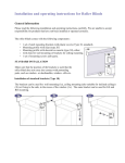
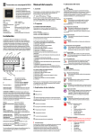
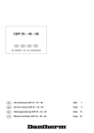
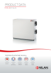
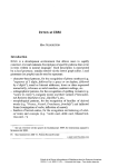
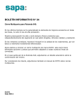
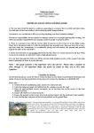
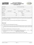
PRODUCT DATA
COMFORT 5000 BY NILAN
Ventilation & passive heat recovery
Commercial
Passive
heat recovery
Ventilation
< 5300 m3/h
COMFORT 5000
The Comfort 5000 is a ventilation unit suitable for central ventilation of residential buildings, schools, offices and business facilities with a ventilation requirement of up to 5300 m3/h.
Every component has been carefully selected with a view to unsurpassed quality and each component is tested throughout the
entire production process, as are the finished units before leaving the factory. This quality control reflects our high standards,
which not only exceed market requirements but also take them
several steps further.
Counterflow heat exchanger
Heat recovery is achieved by four counter flow heat
exchangers made of highly corrosion resistant marine
aluminium. The counterflow heat exchangers have an
energy efficiency of more than 80% and prevent odours
being transferred from the extracted air to the supply
air.
The CTS 602 control allows for cooling recovery
Automatic control
The Comfort 5000 is supplied with an integrated CTS
602 control, which is operated by the enclosed control
panel.
The modern CTS 602 control communicates Modbus
RTU RS485. A CTS system using this type of
communication can easily be connected to the device.
Plug fans
The two fan sections consist of energy-efficient EC motors with built-in motor controllers operated by a 0-10V
signal.
The efficient fan wheels haverear facing impellers and
are extremely quiet.
Doors
The large doors allow easy access for the changing the filters,
as well as servicing of the unit.
Frost protection
An electric heater can be purchased for frost protection. This prevents the formation of ice in the counterflow heat exchanger in the event of long periods
of frost.
The doors are mounted with loockable safty doorhandles.
2
COMFORT 5000 BY NILAN
Modulating 100% bypass
An automatic bypass valve directs the fresh air past
the heat exchanger when waste heat recovery is not
necessary, thus conserving energy.
Filters
The Comfort 5000 is supplied with bag filters. An M5
filter in the air exhaust and an F7 filter for fresh air are
supplied as standard.
The CTS 602 control has a built-in timer controlled
alarm for change of filter. It is possible to install a pressure controlled filter monitor (accessory).
Construction
The Comfort 5000 is housed in a strong frame structure
of Aluzinc with 50 mm insulation.
Base
Comfort 5000 is delivered with a robust built-in base. A
foundation and vibration absorbers can be ordered as
an accessory. This ensures a noiceless installation.
Heating elements
External water or electric heating elements, regulated by the CTS 602 control, can be purchased.
Pressure control
The extraction and/or supply fan can be operated
with the aid of a pressure transmitter.
The water-heating surface can be built into the unit.
3
COMFORT 5000
Technical specifications
Dimensions (W x D x H)
2650 x 1250 x 1500 mm
Weight
617 kg
Min. Airvolume
500 m3/h
Max. Airvolume
5300 m3/h
Power consumption
3.9 kW
Power supply
3 x 400V, 50 Hz
Max. phase
3 x 13 A
Standby power
3W
Plate type casing
Aluzinc steel plate
Heat exchanger type
Aluminium counterflow heat exchanger
Filter class
Standard bagfilters M5 Extract air and F7 Fresh air
Duct connections (WxH)
800 x 500 mm
Condensate drain
PVC, Ø 20×1.5 mm
External leakage underpressure (*1)
< 0,9 %
External leakage overpressure (*2)
< 0,9 %
Internal leakage (*3)
< 0,5 %
Tightness class
IP31
*1 At ± 250 Pa and 4000 m3/h according EN 13141-7.
*2 At ± 250 Pa and 4000 m3/h according EN 13141-7.
*3 At ± 100 Pa and 4000 m3/h according EN 13141-7.
Motor and motor control
Data for ecodesign
Motortype
EC-Engine
Fan data
Motor class in accordance with
IEC 60034-30
IE3 (Premium efficiency)
Max. total efficiency (A-D)
67.9 %
Voltage input
1 x 230 V
ECO measurement set-up (A-D)
A
Current overload protection
Built-in
Efficiency level requirements
62N (2015)
Control signal with third party
control system
0 - 10 V DC
ECO efficiency level during optimal
operating point
75.3
Fluid temperature (air)
-20 / +40 °C
Ambient temperature
(operating)
-20 / +40 °C
Motor data (optimal operating point)
EC-motor
With motor controller
Absorbed power
1.954 kW
Airflow
4863 m3/h
Total pressure
897 Pa
RPM during optimal operating point
2311
Conditions according with EC327/2011
4
COMFORT 5000 BY NILAN
Functional diagram
T10
T3
3
T2
T7
T8
T9
T4
2
1
4
TC
6
5
Connections
Automation
T2/T7: Supply air sensor
T9/TC: Heating element frost protection
T3: Extract air sensor
T4: Discharge air and defrost sensor
T8: Fresh air sensor
T10: Room sensor
1: Fresh air
2: Supply air
3: Extract air
4: Discharge air
5: Condensate drain
6: Electric and water heating
5
PLANNING DATA
Nilan units are tested in accordance with the valid standards of accredited independent test institutes.
Capacity
Capacity of standard unit as a function of qv and Pt, ext.
SFP values according to EN 13141-7 are for standard units with M5-filter in extract air, F7-filter in fresh air and no heating element.
SFP values comprise the unit´s total power comsumption excl. control.
Conversion factor:
J/m3
= W/m3/h
3600
Pa
900
800
700
Max Pa
600
500
400
300
200
2100 J/m3
1800 J/m3
1500 J/m3
100
0
Pressurelos waterheating
0
1000
200
400
2000
600
3000
800
4000
1000 1200
6
5000
6000
1400 1600
qv [m3/h]
qv [l/s]
COMFORT 5000 BY NILAN
Temperature efficiency
Temperature efficiency for unit with counterflow heat exchanger according to EN308 (dry).
Temperature efficiency EN308: ɳ t = (tsupply air-tfresh air)/(textract air-tfresh air)
nt [%]
90
88
86
84
82
80
78
0
1000
2000
3000
4000
5000
qv [m3/h]
qv [l/s]
200
400
600
800
1000
1200
1400
Sound data
Sound data for qV = 4000 m3/h and Pt, ext = 100 Pa according to EN 9614-2 for surfaces and EN 5136 for ducts.
Sound output level LWA drops with falling air volume and falling back pressure.
Sound output level LpA at a given distance will depend on acoustic conditions in the place of installation.
Sound output level (LWA)
Octave band
Hz
Surface
dB(A)
Supply air
dB(A)
Extract air
dB(A)
Outdoor air
dB(A)
Discharge air
dB(A)
125
47,7
61,4
48,7
50,4
60,2
250
50,6
70,1
57,5
59,9
68,5
500
44,9
78,3
54,2
56,7
75,7
1.000
43,7
81,5
53,7
56,4
79,8
2.000
35,7
75,6
47,3
48,8
74,1
4.000
30,9
70,4
33,6
35,4
68,0
8.000
23,2
59,6
14,9
14,6
54,3
Total ±2 dB(A)
53,7
84,3
60,8
63,2
82,4
7
PLANNING DATA
Heating elements (accessory)
Water heating element (for internal fitting)
Mixer circuit proposal
The operating panel
Switch for user choise
(accessory)
Safety switch
Power supply
Extract air
Fresh air
Supply air
Discharge air
T2/T7: Supply air sensor
T9: Heating element frost protection
T3: Extract air sensor
T4: Discharge air and defrost sensor
T8: Fresh air sensor
T10: Room sensor
Electrical heating element (duct mounted)
The operating panel
Switch for user choise
(accessory)
Safety switch
Power supply
Extract air
Fresh air
Power supply
Supply air
Discharge air
8
COMFORT 5000 BY NILAN
Capacity - Heating element (accessory)
Electrical heating surface
The electrical heating surface is fitted in the air inlet duct and connected to
the CTS 602 control panel and 3 x 400 V supply.
The electrical heating surface can supply up to 15 kW or 21 kW of heat.
Water heating element for internal fitting
The water heating element is designed to be built into the system and must be
connected to the primary heating supply and the CTS 602 control. The water heating
element includes copper pipes and aluminium fins.
Capacities can be seen in the table below.
Capacity water heating element
Water side
Temperature
input/output
[°C]
40/30
60/40
70/40
Air side
Flow
Pressure drop
Output
Flow
[m3/h]
Temperature
before WHE*
[°C]
Temperature
after WHE*
[°C]
Pressure drop
over WHE*
[Pa]
[l/h]
[kPa]
[kW]
415
1.7
672
4.1
4.8
1000
16
30.1
3
7.8
2000
16
27.4
9
871
6.5
10.1
3000
16
25.8
18
1036
9.0
12.0
4000
16
24.8
29
1178
11.4
13.7
5000
16
24.0
41
379
1.4
8.7
1000
16
41.6
3
612
3.3
14.1
2000
16
36.6
9
792
5.2
18.2
3000
16
33.8
18
941
7.2
21.7
4000
16
31.9
29
1070
9.1
24.7
5000
16
30.4
41
285
0.8
9.8
1000
16
44.8
3
455
1.9
15.7
2000
16
39.0
9
586
3.0
20.2
3000
16
35.7
18
694
4.0
23.9
4000
16
33.5
29
786
5.1
27.1
5000
16
31.9
41
* Water heating element.
9
AUTOMATION
CTS602 Control
The Comfort 5000 is controlled using its CTS 602 operating
panel, featuring a wide range of functions, e.g., menu-controlled operation, weekly programme settings, filter monitor
with timer, fan speed adjustment, summer bypass (free cooling), post-heating element control, error messages etc.
The CTS 602 comes with factory settings, including a default
setting which can be customised to operational requirements
to achieve optimum operation and utilisation of the system.
The operating panel must be placed in a dry, frost-free location, at least 1.5 m above floor level and at least 0.5 m from
any corner. Avoid placing the panel on an external wall or in
areas in direct sunlight.
Operating instructions for the CTS 602 can be found in a separate user manual supplied with the unit.
External communication
The CTS 602 control unit communicates by default with
Modbus RTU RS485 communication. A CTS system using this
form of communication can easily be connected to the unit.
Nilan units have an open Modbus communication, i.e. not only
can the unit be monitored, but its operation can also be set in
the same way as it can via the operating panel.
CTS / Computer
Konverter
Modbus
The protocol is set up by default for a Modbus RTU 30
address, but can be set to a value between 1 and 247.
A Modbus converter allows you to connect one or more units
to a computer to monitor and control the unit.
10
COMFORT 5000 BY NILAN
Functional overview
+ Standard
- Accessories
3 levels
The control function is divided into 3 levels: User/Service/Factory with various options at each level
+
Weekly plan
There is an option for you to set your own weekly programme.
+
User option 1
This allows you to override the operating mode in the main menu via an external potential-free contact
or PIR sensor.
+
Alarms
Alarm log featuring the last 16 alarms.
+
Filter monitor
Filter monitor with timer (factory setting of 90 days). Adjustable to 30/90/180/360 days.
+
Pressure controlled
filter monitor
It is possible to purchase Comfort 1200 with a pressure controlled filter monitor
-
Bypass
Bypassing the outdoor air reduces heat recovery, enabling the desired supply air temperature to be
maintained spring, summer and autumn.
+
Air quality
Allows you to choose whether to switch humidity sensors and/or CO2 sensors on and off.
-
Humidity control
Allows you to set a higher or lower ventilation step in the case of high/low air humidity.
-
CO2 control
Allows you to set a higher or lower ventilation step in the case of a high/low CO2 level.
-
Air exchange
Allows you to select a low ventilation step in the case of low outside temperatures and air humidity.
+
Defrost function
Temperature-based automatic function for defrosting the heat exchanger.
+
Frostprotection
In case of failing heating system, the unit is turned off to avoid further cooling with a risk of the water
heating coil frost bursting.
+
Temperature control
Allows you to select the temperature sensor which will control the unit.
• T15 ROOM (panel sensor)
• T10 EXT (fitted in a representative extraction valve)
• T3 EXTRACT (extract air)
Room low
Stops the unit at a low room temperature. Hereby is cooling of the home avoided in case of a failing
central heating system. Standard set to OFF. Can be set from 1 to 20 degrees and is controlled by:
• T15 ROOM (panel sensor)
• T10 EXT (fitted in a representative extraction valve)
• T3 EXHAUST (extract air)
+
Room control
Allows you to set the regulator to control the room temperature.
+
Air volume
Allows you to set four ventilation steps. Supply air and extract air are set individually.
Step 1 < 25% - Step 2 < 45% - Step 3 < 70% - Step 4 < 100%
+
Fire alarm
This allows you to connect fire-detecting thermostats, smoke detectors and other fire alarm contacts.
In case of an alarm, smoke dampers are closed and the unit stops.
+
Joint alarm
Outlet for joint alarm
+
Constant pressure control
Allows control from both the extract air and supply air side.
-
Cooling
Via bypass.
This allows you to choose whether to run the system at a higher or the highest ventilation step during
cooling.
The weekly programme has an option for setting cooling at night.
+
Intake air control
Allows you to set the regulator to control the intake air temperature/supply air
(only available if the control unit has been configured for a supply-heating element).
+
External heating element
• Temperature sensor T7 is an supply air sensor
• Integrated frost protection for external water heating element
• Motorised valve and circulation pump control unit
-
External electric heating
element
• Temperature sensor T7 is an supply air sensor
• Overheating protection
-
Delayed start-up
There is a possibility for a delayed start-up by the fans, when a closing damper is installed.
+
Expansion PCB
Allows you to make additional connections, e.g.
• User option 2 overrides User option 1
• Up to 500 W direct
• Can give the signal for external heating if the defrost function is used
• Switching the central heating system on/off
-
Reset
Allows you to restore the factory settings.
+
Manual test
Allows you to test the unit’s functions manually.
+
Language
Option for setting the relevant language (Danish/Finnish/Norwegian/Swedish/German/English/
French).
+
11
+/-
OPERATION
Frost protection
All ventilation units with a counterflow heat exchanger will ice
up if the outdoor temperature is below freezing for a
prolonged period.
ɳt[%]
Consideration must be given to whether the unit’s operation
can be protected during a lengthy period of frost or whether it
is acceptable to decrease its operation.
Temperature efficiency
The extracted air condenses when it is cooled down during heat
recovery. The high temperature efficiency will slowly turn the
condensate to ice, which will block up the counterflow heat
exchanger unless action is taken to remedy this.
With pre-heater
tAußen > -3°C
tAußen < -3°C
Defrost function
Operation Ice building
In homes which are occupied at night, it would be advisable to
protect the unit against frost when the outdoor temperature
is coldest by using a pre-heating element. On the other hand, if
the ventilation is for an office, it may be acceptable to decrease
the operating level at night.
Defrost
Ice building
Defrost
The energy used for the preheating is not wasted, as it ensures
a constant high temperature efficiency
Frost protection
No
Normal operation
After 30 min.
Outdoor temperature
< -3 °C
Yes
Yes
No
Pre-heater
installed
Defrost function
starts when:
Outdoor temp < 1 °C (T8)
Discharge air < 3 °C in 5 min.
Normal operation secured
until outdoor temp. < -12 °C
When outdoor temp. < -12 °C
reduced air volume
Eftervarmeflade
monteret
Ja
Nej
1. The heating element goes up in
operation
2. The bypass damper is opened and
leads the outdoor air past the
heat exchanger
3. Warm exhaust air is blown
through the heat exchanger
4. The ice melts
1. Bypass damper opens
2. The intake motor switches off
3. Warm extracted air will flow
through the heat exchanger
4. The ice is melting
Defrosting stops when:
Discharge air > 7°C (T4)
12
DIMENSIONAL DRAWING
COMFORT 5000 BY NILAN
500
2650
Fresh air
135
1400
Extract air
500
Discharge air
150
100
Supply air
99
1413
Condensation drain
1400
100
150
150
500
500
135
135
500
500
800
800
1000
1250
Recommended service clearance
13
ACCESSORIES
Pressure transmitter
The extraction and/or supply fan can be operated with the aid of one or two pressure
transmitters.
Water heating element incl. regulation
The water heating element is designed to be built into the unit and must be connected to the primary heating supply. Supplied with three-way adjustment valve,
temperature sensor and frost thermostat.
Electrical heating surface incl. regulation
The electrical heating surface is supplied ready to fit into the fresh air duct and, for
easy fitting, the device is pre-fitted with all the required sensors. (15 kW or 21 kW)
Electrical pre-heating element (Frost protection)
Avoid having to defrost the unit, resulting in a loss of power. With temperature
sensors supplied to be fitted in the ducts. (21 kW)
Top cover
If Comfort 5000 is going to be installed outside, it is possible to order a top cover which
protects the unit against rain and snow.
Shut-off damper
Damper for external installation with or without spring-return.
Humidity- and CO2-sensor
For demand control ventilation the unit can be integrated with an humidity- and CO2
-sensor.
Expansion PCB
The expansion PCB provides additional functions for the CTS 602 control.
Vibration dampers
A set of four vibration dampers can be included.
Water trap
The water seal is intended for negative pressure and has a ball to ensure that the
water seal is tight even when not filled with water.
Heating cable
To protect the condensation outlet against frost, a 3 metre-long self-regulating
heating cable can be ordered.
Pressure-regulated filter alarm
Measures the pressure drop across the filter and alerts when the filter is to be replaced.
14
DELIVERY
AND HANDLING
COMFORT 5000 BY NILAN
2650
135
135
1400
500
500
800
500
500
Transport and storage
150
100
150
Comfort 1200 comes in factory packaging that protects it during transport and storage. Comfort 1200 must be stored in a dry
place in its original packaging until installation.
99
The packaging should
only be removed immediately prior to installation.
1413
800
1250
Handling and mowing the Comfort 5000
Comfort 5000 is braced with two tracks at the bottom, which can be used to move the unit with a lifting truck.
Installation conditions
During installation, future service and maintenance should be taken into account. We recommend a minimum
gap in front of the unit of 1 m.
1000
The unit must be installed level for the sake of the condensate drain. The condensate drain requires clearance of
min. 12,5 cm under the drain nozzle.
15
Service clearance
(unit shown from above)
INFORMATION FROM A TO Z
Brochure
Product data
General information
about the solution
and its benefits.
Technical information
to ensure correct
choice of solution.
Nilan A/S
Nilanvej 2
8722 Hedensted
Danmark
Tlf. +45 76 75 25 00
Fax +45 76 75 25 25
[email protected]
www.nilan.dk
User manual
Detailed guide for
Detailed guide for instal- regulation of the
lation and initial adjust- solution to ensure
ment of the
optimum day-to-day
solution.
operation.
Drawings
Tender documents
and 3D drawings are
available to download for planning
purposes.
Visit us at www.nilan.dk to find out
more about our company and solutions,
download further information and find
your nearest dealer.
Ver. 2.05 - 2015.02
WWW.NILAN.DK
Installation
instructions
Nilan A/S assumes no responsibility for any errors or omissions in the printed information material or for loss or damage that may follow from the use of such published materials - whether such loss of damage is caused by errors or
inexpediencies in the material or otherwise. Nilan A/S reserves the right without prior notice to change products and information material. All trademarks are the property of Nilan A/S. All rights reserved.
Nilan develops and manufactures premium-quality, energy-saving ventilation and heat pump solutions
that provide a healthy indoor climate and low-level energy consumption with the greatest consideration for
the environment. In order to facilitate each step in the construction process – from choosing the solution
through to planning, installation and maintenance – we have created a series of information material which
is available for download at www.nilan.dk.