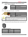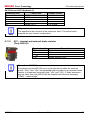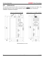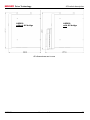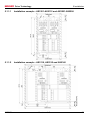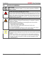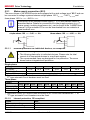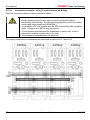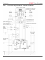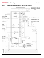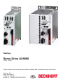
1
Startup Servo Drive AX5000 (1.5 A – 40 A) Please read this document carefully before installing and commissioning the servo drive. Version : 4.5 Date: 2015-04-01 Language: English Article no.: TDmlAX-5000-0000-0200 BECKHOFF BECKHOFF Drive Technology 1 Foreword Notes: 2 Version : 4.5 AX5000 BECKHOFF Drive Technology 1 Foreword Chapter Table of Contents - AX5000 Startup 1 Page Foreword............................................................................................................... 5 Notes on the documentation............................................................................... 5 Disclaimer........................................................................................................... 5 Trademarks ........................................................................................................ 5 Patent Pending ................................................................................................... 5 Copyright ............................................................................................................ 6 Documentation issue status ............................................................................... 6 Appropriate use .................................................................................................. 7 Dual Use (EU 1384/2014) .................................................................................. 7 Documented servo drives ................................................................................... 8 2 Safety .................................................................................................................... 9 2.1 General safety instructions ................................................................................. 9 2.1.1 Safety rules ........................................................................................................ 9 2.1.2 Disclaimer........................................................................................................... 9 2.1.3 Description of safety symbols ............................................................................. 9 2.1.4 Personnel qualification ..................................................................................... 10 2.2 Special safety instructions for AX5000 ............................................................. 10 3 Guidelines and Standards ................................................................................. 12 3.1 CE conformity ................................................................................................... 12 3.2 Electromagnetic compatibility ........................................................................... 12 3.3 UL-Listing in USA and Canada......................................................................... 13 3.3.1 UL-specific chapter changes ............................................................................ 13 3.3.2 UL-specific chapter ........................................................................................... 13 3.3.3 UL-specific notes .............................................................................................. 14 3.4 Electrical isolation according to EN 50178 / VDE 160 ...................................... 14 4 Product description ........................................................................................... 15 4.1 Type code......................................................................................................... 15 4.2 Scope of supply ................................................................................................ 15 4.2.1 Standard scope of supply ................................................................................. 15 4.2.2 Accessories ...................................................................................................... 16 4.3 Name plate ....................................................................................................... 16 4.4 Technical data .................................................................................................. 17 4.4.1 Permissible ambient and operating conditions ................................................. 17 4.4.2 Electrical data - single-channel servo drive (AX51xx)....................................... 17 4.4.2.1 Single-phase connection .................................................................................. 17 4.4.2.2 Three-phase connection ................................................................................... 18 4.4.3 Electrical data - two-channel servo drive (AX52xx) .......................................... 19 4.4.3.1 Single-phase connection .................................................................................. 19 4.4.3.2 Three-phase connection ................................................................................... 19 4.4.4 Mechanical data (single-channel servo drive) .................................................. 20 4.4.5 Mechanical data (two-channel servo drive) ...................................................... 20 4.5 General overview (AX5101 – AX5112 and AX520x) ........................................ 21 4.6 General overview (AX5118, AX5125 und AX5140) .......................................... 22 4.7 Overview of connectors/terminal points ............................................................ 23 1.1 1.2 1.3 1.4 1.5 1.6 1.7 1.7.1 1.8 AX5000 Version : 4.5 3 BECKHOFF Drive Technology 1 Foreword 4.7.1 4.7.2 4.7.3 4.7.4 4.7.5 4.7.6 4.7.7 4.7.8 4.7.9 4.7.10 4.7.11 4.7.12 4.8 X01 - wide voltage input ................................................................................... 23 X02 - DC link (AX5101 - AX5125 und AX520x)................................................ 23 X02 - DC link (Only AX5140)............................................................................ 23 X03 - 24 VDC supply ......................................................................................... 23 X04, X05 - EtherCAT connection ..................................................................... 24 X06 – Digital I/Os ............................................................................................. 24 X11 (channel A) , X21 (channel B) - feedback, high-resolution ........................ 25 X12 (channel A) , X22 (channel B) - resolver/hall ............................................ 25 X13 (channel A) , X23 (channel B) - motor connection (power) ....................... 26 X13 - motor connection (power - only AX5140)................................................ 26 X14 (channel A), X24 (channel B)-motor brake, thermal contact, OCT............ 26 X07 – internal and external brake resistor ........................................................ 27 Dimensions ...................................................................................................... 28 5 Installation .......................................................................................................... 30 5.1 Mechanical installation ..................................................................................... 30 5.1.1 Installation in the control cabinet ...................................................................... 30 5.1.1.1 Installation example - AX5101-AX5112 and AX5201-AX5206 ......................... 31 5.1.1.2 Installation example - AX5118, AX5125 and AX5140 ...................................... 31 5.2 Electrical installation......................................................................................... 32 5.2.1 Mains supply connection (X01) ........................................................................ 33 5.2.1.1 External protection for individual devices, CE-compliant .................................. 33 5.2.1.2 Internal protection, CE-compliant ..................................................................... 33 5.2.1.3 External protection, UL-compliant .................................................................... 34 5.2.1.4 Internal protection, UL-compliant ..................................................................... 34 5.2.1.5 External drive system protection ...................................................................... 35 5.2.2 24 VDC - supply network connection (X03) ....................................................... 36 5.2.3 Connection of several servo drives to form a drive system .............................. 36 5.2.3.1 Connection example - module AX5901 and AX5911 (AX Bridge) .................... 37 5.2.3.2 Connection example - wiring in series without AX Bridge ................................ 38 5.2.4 Configuration example, general ....................................................................... 39 5.2.5 Connection diagram AX5101 – AX5112 and AX520x ...................................... 40 5.2.6 Connection diagram AX5118, AX5125 and AX5140 ........................................ 41 5.3 Motors and cables ............................................................................................ 42 6 Important information for commissioning....................................................... 43 7 Project planning – important information........................................................ 44 7.1 Drive train design ............................................................................................. 44 7.1.1 Control quality, mass inertia ratio and load connection .................................... 44 7.2 Energy management ........................................................................................ 44 7.3 EMC, earthing, screen connection and potential .............................................. 45 7.4 Control cabinet ................................................................................................. 45 8 Appendix ............................................................................................................ 46 8.1 Support and Service ......................................................................................... 46 8.1.1 Beckhoff's branch offices and representatives ................................................. 46 8.1.2 Beckhoff Headquarters..................................................................................... 46 8.1.3 Beckhoff Support.............................................................................................. 46 8.1.4 Beckhoff Service .............................................................................................. 46 4 Version : 4.5 AX5000 BECKHOFF Drive Technology 1 Foreword 1 Foreword 1.1 Notes on the documentation This description is only intended for trained specialists in control, automation and drive engineering who are familiar with the applicable national standards. It is essential that the following notes and explanations are followed when installing and commissioning these components. The responsible staff must ensure that the application or use of the products described satisfy all the requirements for safety, including all the relevant laws, regulations, guidelines and standards. The "General safety instructions" and "Special safety instructions for AX5000" sections are also essential. Hazard to individuals! CAUTION Further and more detailed information regarding the individual sections and safety can be found in the “AX5000 User manual” on the enclosed CD or can be downloaded from our website at www.beckhoff.com. If you do not have access to the “AX5000 User manual” please refrain from working on the AX5000 and notify our support division. An overview is provided on the inside of the rear cover, which can be folded out. 1.2 Disclaimer The documentation has been prepared with care. The products described are, however, constantly under development. For this reason, the documentation may not always be have been fully checked for consistency with the performance data, standards or other characteristics described. In the event that it contains technical or editorial errors, we retain the right to make alterations at any time and without warning. No claims for the modification of products that have already been supplied may be made on the basis of the data, diagrams and descriptions in this documentation. 1.3 Trademarks ® ® ® ® ® ® Beckhoff , TwinCAT , EtherCAT , Safety over EtherCAT , TwinSAFE and XFC are registered trademarks of and licensed by Beckhoff Automation GmbH. Other designations used in this publication may be trademarks whose use by third parties for their own purposes could violate the rights of the owners. 1.4 Patent Pending The EtherCAT Technology is covered, including but not limited to the following patent applications and patents: EP1590927, EP1789857, DE102004044764, DE102007017835 with corresponding applications or registrations in various other countries. The TwinCAT Technology is covered, including but not limited to the following patent applications and patents: EP0851348, US6167425 with corresponding applications or registrations in various other countries. AX5000 Version : 4.5 5 BECKHOFF Drive Technology 1 Foreword 1.5 Copyright © Beckhoff Automation GmbH & Co. KG The reproduction, distribution and utilization of this document as well as the communication of its contents to others without express authorization are prohibited. Offenders will be held liable for the payment of damages. All rights reserved in the event of the grant of a patent, utility model or design. 1.6 Version 4.5 4.4 4.3 4.2 4.1 4.0 3.9 3.8 3.7 3.6 3.5 3.4 3.3 3.2 3.1 6 Documentation issue status Comment New chapter: 5.2.5; 5.2.6 Chapter-Update: 4.7.11; 5.2.1.1 Chapter-Update: 4.4.2; 4.4.3 New chapter: 1.7.1 Chapter-Update: 1.5; 2.1.2; 4.3; 5.3; 8.1.2 Deleted chapter: 7.5 New chapter: 5.3 General revision General revision on account of the cULus-Listing of the AX5000. Chapter-Update: 4.7.4 Chapter-Update: 4.3; 4.4.1; 4.7.11; 7.5 Chapter-Update: 1.1; 4.4.4; 5.1.1.2 Chapter-Update: 2.2; 4.4.2.2; 4.6; 4.7.11 Chapter-Update: 6 Chapter-Update: 4.7.11 New chapter: 4.7.3 Chapter-Update: 4.7.2 Chapter-Update: 4.7.11; 5.2.1.1; 7.5 Version : 4.5 AX5000 BECKHOFF Drive Technology 3.0 Chapter-Update: 4.2.1; 4.4.2.2; 4.4.4; 4.8; 5.1.1.2; 5.2.1.1 New chapter: 1.8; 4.6; 4.7.9; 4.7.11; 7 Chapter-Update: 4.6.7; 6 Chapter-Update: 1.1; 1.2; 1.5; 4.5; 5.2 New chapter: 1.3; 1.4 Chapter-Update: 2.2; 5.2.3.1 New chapter: 6 Chapter-Update: 2.2; 3.1; 4.6.6; 4.6.8; 5.1.1; 5.2.1.5 Chapter-Update: 4.1; 4.6.6; 5.2.3 General revision on account of the UL-Listing of the AX5000. Chapter-Update: 1.1; 4.4.2.1; 4.4.2.2; 4.4.3.1; 4.4.3.2; 5.2.1; 5.2.1.1 General routine corrections First edition only german 2.5 2.4 2.3 2.2 2.1 2.0 1.3 1.2 1.1 1.0 1.7 1 Foreword Appropriate use The servo drives of the AX5000 series are exclusively designed for torque, speed and position control of suitable asynchronous and synchronous three-phase current motors. The maximum permissible effective motor voltage must be at least equal the effective mains voltage fed into the servo drive. The servo drives from the AX5000 series are designed for installation as components in electrical systems or machines and may be operated only as integrated system or machine components. Caution – Risk of injury! WARNING Electronic equipment is not fail-safe. The machine manufacturer is responsible for ensuring that the connected motors and the machine are brought into a safe state in the event of a fault in the drive system. The servo drives may only be operated in enclosed control cabinets and in accordance with the conditions described in the "Technical data" section. 1.7.1 Dual Use (EU 1384/2014) As published on December 30, 2014 by EU Commission Delegated Regulation 1382/2014, standard frequency inverters – and with that also Beckhoff products AX5000 – become newly classified Dual-Use items: the item list Annex I of the Dual-Use AX5000 Version : 4.5 7 BECKHOFF Drive Technology 1 Foreword Council Regulation 428/2009 has been changed accordingly, Frequency inverters (listed in item position 3A225) with „operating frequency of 600 Hz or more“ are now export controlled items. As a consequence some modifications have to be noticed. Firmware versions without extension (Dual Use) can be used in consideration of Hardware Versions with following drives: • HW Version 1.0 (AX5xxx-0000-x0xx): Serial Number < 68.000 • HW Version 2.0 (AX5xxx-0000-x2xx): Serial Number < 140.000 • HW Version 2.0 (AX5xxx-0000-x21x) Firmware versions with extension (Dual Use) can be used in consideration of Hardware Versions with all drives 1.8 Documented servo drives This documentation describes the following servo drives in the AX5000 range: AX5101 AX5103 AX5106 AX5112 AX5118 AX5125 AX5140 AX5201 AX5203 AX5206 8 Version : 4.5 AX5000 BECKHOFF Drive Technology 2 Safety 2 Safety 2.1 General safety instructions 2.1.1 Safety rules Consider the following safety instructions and descriptions! Product specific safety instructions are to be found on the following pages or in the areas mounting, wiring, commissioning etc.. 2.1.2 Disclaimer All the components are supplied in particular hardware and software configurations appropriate for the application. Modifications to hardware or software configurations other than those described in the documentation are not permitted, and nullify the liability of Beckhoff Automation GmbH & Co. KG. 2.1.3 Description of safety symbols The following safety symbols with a adjoining safety advise are used in this manual. You have to read the adjoining safety advice carefully and adhere it strictly. DANGER WARNING CAUTION Attention Acute risk of injury! If you do not adhere the safety advise adjoining this symbol, there is immediate danger to life and health of individuals! Risk of injury! If you do not adhere the safety advise adjoining this symbol, there is danger to life and health of individuals! Hazard to individuals! If you do not adhere the safety advise adjoining this symbol, there is obvious hazard to individuals! Hazard to devices and environment If you do not adhere the notice adjoining this symbol, there is obvious hazard to materials and environment. Note or pointer This symbol indicates information that contributes to better understanding. Note UL pointer This symbol indicates important information about the UL-compliant. AX5000 Version : 4.5 9 BECKHOFF Drive Technology 2 Safety 2.1.4 Personnel qualification This description is only intended for trained specialists in control, automation and drive engineering who are familiar with the applicable national standards. 2.2 Special safety instructions for AX5000 The safety instructions are designed to avert danger and must be followed during installation, commissioning, production, troubleshooting, maintenance and trial or test assemblies. The servo drives of the AX5000 series are not designed for stand-alone operation and must always be installed in a machine or system. After installation the additional documentation and safety instructions provided by the machine manufacturer must be read and followed. Serious risk of injury through high electrical voltage! WARNING • Never open the servo drive when it is live. Wait until the DC link capacitors are discharged. The voltage measured between the DC+ and DC- terminals (X02) must have fallen below 50 V. Opening the device (with the exception of expansion card slots) invalidates all warranty and liability claims against Beckhoff Automation GmbH. • Negligent, improper handling of the servo drive and bypassing of the safety devices can lead to personal injury or death through electric shock. • Ensure that the protective conductor is connected properly. • Disconnect the servo drive from the mains supply and secure it against reconnection before connecting or disconnecting the pluggable terminals. • Disconnect the servo drive from the mains supply and secure it against reconnection before working on electrical parts with a voltage > 50 V. • Due to the DC link capacitors dangerous voltage may persist at the DC link contacts "X02" after the servo drive has been disconnected from the mains supply. After disconnecting the servo drive wait 5 minutes and measure the voltage at the DC link contacts DC+ and DC-. The device is safe once the voltage has fallen below 50 V. Serious risk of injury through hot surfaces! WARNING • The surface temperature may exceed 50 °C, resulting in a risk of burns. • Avoid touching the case during or shortly after operation. • Leave the servo drive to cool down for at least 15 minutes after it is switched off. • Use a thermometer to check whether the surface has cooled down sufficiently. Danger of injury due to uncontrolled movements! WARNING 10 Read and take note of chapter 6 ‘Important information for commissioning’ each time before commissioning the AX5000 Version : 4.5 AX5000 BECKHOFF Drive Technology 2 Safety Hazard to individuals! CAUTION • Carefully read this manual before using the servo drive thoroughly, paying particular attention to the safety instructions. In the event of any uncertainties please notify your sales office immediately and refrain from working on the servo drive. • Only well trained, qualified electricians with sound knowledge of drive equipment may work on the device. • During the electrical installation it is essential to ensure that the correct fuses/protective circuit breakers are used between the mains supply and the servo drive. Further information can be found in the "Electrical installation" section. • If a servo drive is installed in a machine it must not be commissioned until proof of compliance of the machine with the latest version of the EC Machinery Directive has been provided. This includes all relevant harmonised standards and regulations required for implementation of this Directive in national legislation. Hazard to devices and environment Attention AX5000 • During installation it is essential to ensure that the specified ventilation clearances and climatic conditions are adhered to. Further information can be found in the "Technical data" and "Mechanical installation" sections. • If the servo drive is operated in contaminated ambient air, the cooling openings must be checked regularly for blockage. These checks should be carried out several times per day. • The servo drives contain components at risk from electrostatic discharge caused by improper handling: - Please ensure you are electrostatically discharged before touching the servo drive directly. - Avoid contact with highly insulating materials (synthetic fibres, plastic film etc.). - Place the servo drive on a conductive surface. - Do not touch the motor plug during operation of the AX5000. Version : 4.5 11 BECKHOFF Drive Technology 3 Guidelines and Standards 3 Guidelines and Standards 3.1 CE conformity The servo drives of the AX5000 series comply with the • EC Low-Voltage Directive, 2006/95/EC Applied harmonised standards: 61800-5-1 CAUTION 3.2 Hazard to individuals! Servo drives are not covered by the EC Machinery Directive. Operation of the servo drives in machines or systems is only permitted once the machine or system manufacturers has provided evidence of CE conformity of the complete machine or system. Electromagnetic compatibility The servo drives of the AX5000 series comply with the • 2004/108/EC EMC Directive Applied harmonised standards: IEC / EN 61000-4-2 IEC / EN 61000-4-3 IEC / EN 61000-4-4 IEC / EN 61000-4-5 IEC / EN 61000-4-6 IEC / EN 61000-6-1 IEC / EN 61000-6-2 IEC / EN 61000-6-3 IEC / EN 61000-6-4 IEC / EN 61800-3 12 Version : 4.5 AX5000 BECKHOFF Drive Technology 3.3 3 Guidelines and Standards UL-Listing in USA and Canada The following servo drives from the AX5000 series have a UL-Listing and must bear the CUS symbol AX5000 with UL-Listing AX5101, AX5103, AX5106, AX5112, AX5118, AX5125, AX5140, AX5201, AX5203 und AX5206 on the name plate. If you wish to operate an AX5000 in USA or Canada , please check that there is a CUS symbol on the name plate. Below is a list of the relevant chapters that are amended with respect to the UL-Listing. Furthermore, UL-specific remarks are listed. It is essential to observe these specifications. 3.3.1 “5.2.1 UL-specific chapter changes Mains supply connection (X01)” AX5000 shall be connected only to a grounded wye-source where the maximum voltage does not exceed 277 V to ground. “5.2.3 Connection of several servo drives to form a drive system” Drive system with UL-Listing! Please consult our Application Department with respect to the requirements for a drive system with UL-Listing. 3.3.2 UL-specific chapter “5.2.1.3 External protection, UL-compliant” Integral solid state short circuit protection does not provide branch circuit protection. Branch circuit protection must be provided in accordance with the Manufacture Instructions, National Electrical Code and any additional local codes. Suitable for use on a circuit capable of delivering not more than 18000 rms symmetrical amperes, 480 V maximum, when protected by RK5 class fuses. Single-phase Fusing AX5101 AX5103 AX5106 AX5201 AX5203 AX5206 *) AC supply (max.) 6A 12 A 20 A 12 A 20 A 20 A 24 V supply (max.) 3A Brake resistor electronic *) Mains fuses according to type “RK5” must be used. Three-phase AX Fusing *) 5101 5103 5106 5112 5118 5125 AC suppl (max.) 6 A 12 A 20 A 20 A 35 A 45 A 24 V supply (max.) 3 AT Brake resistor elektronisch *) Mains fuses according to type “RK5” must be used. AX5000 Version : 4.5 5140 80 A 5201 12 A 5203 20 A 5206 20 A 13 BECKHOFF Drive Technology 3 Guidelines and Standards When protected by RK5 class fuses: AX5112 Rated 20 A, min. 480 V AX5118 Rated 35 A, min. 480 V AX5125 Rated 45 A, min. 480 V AX5140 Rated 80 A, min. 480 V 3.3.3 UL-specific notes Use in a Pollution Degree 2 environment Use 75 °C Copper Conductors min. Control Board rating = 24 V Drive intended for use over a range of motor sizes. Internal motor overload protection level is adjustable: The internal motor protection is parameterised via the IDN P-0-0062 “Thermal motor model”, based on the value of the IDN S-0-0111 “Motor continuous stall current”. The IDN P-0-0062 “Time constant” is specified by the motor manufacturer and must be entered here. The IDN P-0-0062 “Warning limit” (Default) is responsible for deciding when a warning is to be generated. The IDN P-0-0062 “Error limit” (Default) is responsible for deciding when the motor is to be switched off. The default values take into account the specific characteristics of the servomotors. Canada! In Canada use only in combination with unit AX2090-TS50, manufactured by Beckhoff Automation. 3.4 Electrical isolation according to EN 50178 / VDE 160 The power section (motor connection, DC link connection and mains connection) and the control unit are doubly insulated against each other, so that safe protection against accidental contact is ensured at all terminals of the control unit without additional measures. The air and creepage distances also meet the requirements of the above standard. 14 Version : 4.5 AX5000 BECKHOFF Drive Technology 4 4 Product description Product description The servo drives of the AX5000 series are available as single- or multi-channel versions and are optimised in terms of function and cost-effectiveness. In conjunction with EtherCAT, the real-time Ethernet system, the integrated control technology offers minimum cycle times and supports fast, highly dynamic positioning tasks. 4.1 Type code A X 5 X Y Z - a b c d Product line: Servo Drives Version: 0 = Standard 1 = Customer-specific Series: 5000 Hardware features: 00 = Standard 01 = Cold Plate 02 = Auxiliary fan Number of channels: 1 = single-channel 2 = two-channel --- Rated current per channel Single-channel units: 01, 03, 06, 12, 18, 25, 40, 60, 72, 90 or: 91 = 110 A 92 = 143 A 93 = 170 A Two-channel units: 01, 03, 06 4.2 Scope of supply The scope of delivery may vary depending on the ordered configuration. Before installing the device please ensure that all ordered components were delivered and that they are undamaged. In the event of any damage please contact the carrier immediately and document the damage. 4.2.1 Standard scope of supply − AX5000 in the performance class according to the order − Connectors for: X01: Mains input X02: DC link X03: DC power supply 24 V X06: Digital inputs and outputs X07: External brake resistor (only AX5140) − Startup (this manual) − Complete documentation on CD AX5000 Version : 4.5 15 BECKHOFF Drive Technology 4 Product description 4.2.2 Accessories A comprehensive list of accessories can be found in the complete Beckhoff catalogue or on our website at www.beckhoff.com. Accessories with UL-Listing! If you wish to operate an AX5000 in USA or Canada , please make sure that the accessories also have a UL-Listing. 4.3 Name plate The servo drive features two name plates. A comprehensive name plate can be found on the right-hand side. An extract showing the main data can be found at the top of the servo drive. Small name plate Large name plate 1 2 3 4 5 16 Catalog number Max. ambient temperature Input rated voltage Input rated current Input frequency 6 7 8 9 10 Output rated voltage Output rated current Output frequency range Protection class Serial number Version : 4.5 11 12 13 14 Customer-specific wye-source only CE - Conform cULus – Listed AX5000 BECKHOFF Drive Technology 4.4 4 Product description Technical data UL-Listing! It is essential to observe chapter 3.3 if you wish to operate an AX5000 in USA or Canada. 4.4.1 Permissible ambient and operating conditions Ambient / operating conditions Ambient temperature during operation Ambient temperature during transport / storage Air humidity Pollution degree Corrosion protection Operating altitude Installation position Ventilation Protection class Vibration test (EN 60068-2-6) Shock test (EN 60068-2-27) Repetitive shock test (EN 60068-2-27) EMC Permissible values 0 °C to +50 °C -25 °C to +70 °C 5 % to 95 %, non-condensing 2 according to EN 60204/EN 50178 Normally not required. Under extreme operating conditions separate measures must be agreed with the manufacturer. up to 1000 m above sea level vertical Total device current ≤ 3 A: free convection Total device current > 3 A: built-in temperaturecontrolled fan IP 20 Frequency range: 10-500 Hz Amplitude: 10-58 Hz = 0,075 mm pk-pk 59-500 Hz = 1 g Half sine wave amplitude: 5 g Duration: 30 ms Number of shocks: 3 per axis and direction (total 18) Half sine wave amplitude: 5 g Duration: 30 ms Number of shocks: 1000 per axis and direction (total 6000) Category C3 - standard Category C2, C1 - auxiliary filter required 4.4.2 Electrical data - single-channel servo drive (AX51xx) 4.4.2.1 Single-phase connection Electrical data Rated output current Minimum channel current at full current resolution (1) Max. output current Rated supply voltage Max. DC link voltage Rated apparent power AX5000 AX5101 1.5 A AX5103 3A AX5106 4.5 A 0.35 A 1A 1A 4.5 A Version : 4.5 7.5 A 13 A 1x 100-10% – 240+10% VAC 890 VDC 17 BECKHOFF Drive Technology 4 Product description Electrical data S1 mode (selection) 120 V 230 V (2) Power dissipation Max. continuous braking power (with internal brake resistor) Max. braking power (with internal brake resistor) Min. brake resistor (external brake resistor) Max. braking power (with external brake resistor) AX5101 AX5103 AX5106 0.3 kVA 0.6 kVA 35 W 0.6 kVA 1.2 kVA 50 W 1.2 kVA 2.4 kVA 85 W 50 W 50 W 150 W 14 kW 47 Ω 15 kW (1) Ieff for max. 7 s S1 mode, including power supply unit, without brake chopper 4.4.2.2 Three-phase connection (2) Electrical data 5101 [A] 1,5 [A] 0,35 Rated output current Minimum channel current at full current resolution (3) Max. output current [A] Rated supply voltage [VAC] Max. DC link voltage [VDC] Rated apparent power [kVA] S1-mode (selection) 120 V 230 V 400 V 480 V (5) Power dissipation [W] Max. continuous braking power [W] (with internal brake resistor) Max. braking power [kW] (with internal brake resistor) Min. brake resistor [Ω] (external brake resistor) Max. braking power [kW] (external brake resistor) 5103 3 5106 6 AX 5112 12 5118 18 5125 (1) 25 5140 40 1 1 6 8 12 18 13 26 36 (2) 3x 100-10% – 480+10% 890 7,5 0,3 0,6 1,0 1,2 35 0,6 1,2 2,1 2,5 50 1,2 2,4 4,2 5,0 85 2,5 4,8 8,3 10,0 160 3,4 7,2 12,5 15,0 255 4,8 10,0 17,3 20,8 340 8,3 16,0 27,7 33,3 510 50 50 150 90 200 200 150 26 26 26 14 50 47 47 47 30 22 22 15 15 15 23,5 32 32 80 (4) 4,5 22 (4) 32 (1) cULus = 24 A cULus = AX5118 und AX5125 = 3 x 480 VAC ± 10% (3) Ieff for max. 7 s (4) Ieff for max. 7 s, if rotating field frequency >3 Hz at max. 40°C (5) S1 mode, including power supply unit, without brake chopper (4) Brake resistor < 22 Ω –> Please consult our Application Department (2) 18 Version : 4.5 AX5000 BECKHOFF Drive Technology 4 Product description 4.4.3 Electrical data - two-channel servo drive (AX52xx) 4.4.3.1 Single-phase connection Electrical data AX5201 AX5203 AX5206 Rated output current / channel 1.5 A 3A 6A Minimum channel current at full current 0.35 A 1A 1A resolution Maximum rated channel current 3A 4.5 A 9A Total rated output current 3A 4.5 A 9A (1) Max. output current /channel 5A 10 A 13 A (1) Max. output current total device 10 A 20 A 26 A current Rated supply voltage 1x 100-10% – 240+10% VAC Max. DC link voltage 890 VDC Rated apparent power S1 mode (selection) 120 V 0.6 kVA 1.2 kVA 2.5 kVA 230 V 1.2 kVA 2.4 kVA 4.8 kVA (2) Power dissipation 55 W 85 W 160 W Max. continuous braking power 50 W 150 W 90 W (with internal brake resistor) Max. braking power 14 kW (with internal brake resistor) Min. brake resistor 47 Ω (external brake resistor) Max. braking power 15 kW (with external brake resistor) (1) (2) Ieff for max. 7 s S1 mode, including power supply unit, without brake chopper 4.4.3.2 Three-phase connection Electrical data AX5201 AX5203 AX5206 Rated output current per channel 1.5 A 3A 6A Minimum channel current at full current 0.35 A 1A 1A resolution Maximum rated channel current 3A 6A 9A Total rated output current 3A 6A 12 A (1) Max. output current /channel 5A 10 A 13 A (1) Peak output current total device 10 A 20 A 26 A current Rated supply voltage 3x 100-10% – 480+10% VAC Max. DC link voltage 890 VDC Rated apparent power S1 mode (selection) 120 V 0.6 kVA 1.2 kVA 2.5 kVA AX5000 Version : 4.5 19 BECKHOFF Drive Technology 4 Product description Electrical data 230 V 400 V 480 V (2) Power dissipation Max. continuous braking power (with internal brake resistor) Max. braking power (with internal brake resistor) Min. brake resistor (external brake resistor) Max. braking power (with external brake resistor) (1) (2) AX5201 1.2 kVA 2.1 kVA 2.5 kVA 55 W AX5203 2.4 kVA 4.2 kVA 5.0 kVA 85 W 50 W 150 W AX5206 4.8 kVA 8.3 kVA 10.0 kVA 160 W 90 W 14 kW 47 Ω 15 kW Ieff for max. 7 s S1 mode, including power supply unit, without brake chopper 4.4.4 Mechanical data (single-channel servo drive) Mechanical data 5101 Weight [kg] ca. 4 Width [mm] Height without plugs [mm] Depth without connectors/ [mm] accessories 4.4.5 5103 ca. 4 92 5106 ca. 5 274 232 5118 5125 5140 ca. 11 ca. 11 ca. 13 185 Mechanical data (two-channel servo drive) Mechanical data AX5201 Weight approx. 5 kg Width Height without plugs Depth without connectors / accessories 20 AX 5112 ca. 5 Version : 4.5 AX5203 approx. 6 kg 92 mm 274 mm 232 mm AX5206 approx. 6 kg AX5000 BECKHOFF Drive Technology 4.5 4 Product description General overview (AX5101 – AX5112 and AX520x) The servo drive shown below is a two-channel device. Components that are only available for the second channel are identified in the item description. Item description: No Designation 1 X11 – feedback connection, encoder 2 X12 – feedback connection, resolver 3 X21 – feedback connection, encoder channel B (only for two-channel unit) 4 X22 – feedback connection, resolver channel B (only for two-channel unit) 5 X3x – optional slot for safety card X4x – optional slot for expansion cards 6 Navigation rocker 7 Status LED for EtherCAT output 8 Labeling field 9 X05 – socket for EtherCAT output 10 X03 – power supply 24 V DC input 11 X14 – sensor for motor temperature and brake 12 X24 – sensor for motor temperature and brake channel B (only for two-channel unit) 13 X23 – motor connection (U, V, W, PE) channel B (only for two-channel unit) 14 X13 – motor connection (U, V, W, PE) 15 X01 – mains supply 100 – 480 V 16 X02 – DC link output (890 V DC voltage) Connection for the external brake resistor 17 890 V DC voltage at the DC link terminals. Dangerous voltage may be present for 5 minutes after the WARNING device is switched off. The device is safe once the voltage has fallen below 50 V. 18 X04 – socket for EtherCAT input 19 Labeling field 20 Status LED for EtherCAT input 21 Display 22 X06 – connection for digital inputs and outputs AX5000 Version : 4.5 21 BECKHOFF Drive Technology 4 Product description 4.6 General overview (AX5118, AX5125 und AX5140) The servo drive illustrated below is an AX5140; the devices with 18 A or 25 A are structurally similar apart from pos. 11 "X07" (external brake resistor). Item description: No Designation 1 X11 – feedback connection, encoder 2 3 4 X12 – feedback connection, resolver X3x – optional slot for safety card X4x – optional slot for expansion cards Navigation rocker No Designation 11 X07 – external brake resistor (only AX5140) 12 X13 – motor connection (U, V, W, PE) 13 X01 – mains supply 100 – 480 V 14 X02 – DC link output (890 V DC voltage) Connection for the external brake resistor (only AX5118 u. AX5125) 5 Status LED for EtherCAT output 15 X04 – socket for EtherCAT input 6 Labeling field 16 Labeling field 7 X05 – socket for EtherCAT output 17 Status LED for EtherCAT input 8 X03 – power supply 24 V DC input 18 Display 9 Max. 890 V DC voltage at the 19 X06 – connection for digital inputs and outputs DC link terminals. Dangerous voltage may be present for 5 WARNING minutes after the device is switched off. The device is safe once the voltage has fallen below 50 V. 10 X14 – sensor for motor temperature and brake 22 Version : 4.5 AX5000 BECKHOFF Drive Technology 4 Product description 4.7 Overview of connectors/terminal points 4.7.1 X01 - wide voltage input Connection 3-phase 1-phase Phase L1 Phase L1 Phase L2 not used Phase L3 Neutral conductor Protective conductor Terminal point L1 L2 L3/ N PE 4.7.2 0,5 -0,6 Nm X02 - DC link (AX5101 - AX5125 und AX520x) Terminal point Connection DC+ DC – 4.7.3 Tightening torque DC link + DC link – external brake resistor and drive system Tightening torque 0,5 -0,6 Nm X02 - DC link (Only AX5140) Terminal point Connection DC+ DC – DC link + DC link – only for drive system Tightening torque 1,2 -1,5 Nm Serious risk of injury through high electrical voltage! WARNING 4.7.4 890 V DC voltage at the DC link terminals. Dangerous voltage may be present for 5 minutes after the device is switched off. Remove the connector only if you want to build a drive system with a AXBridge. Remove the white hexagon plugs only if you wire the terminal points again. X03 - 24 VDC supply Terminal point Up + Us + GND AX5000 Connection 24 VDC -0/+25% - periphery (e.g. separate braking voltage) 24 VDC ±25% - system supply (depending on rated current) GND Version : 4.5 Current consumption Depending on the connected consumers (see X06 and X14,X24) -12 A = 0.4 A – 0.8 A 18 A - 25A = 1,1 A 40 A = 1,6 A Tightening torque 0,5 – 0,6 Nm 23 BECKHOFF Drive Technology 4 Product description 4.7.5 X04, X05 - EtherCAT connection Terminal point X04 (IN) X05 (OUT) 4.7.6 Connection incoming EtherCAT line outgoing EtherCAT line X06 – Digital I/Os Destruction of the AX5000! CAUTION This connector is not designed for external power supply. It is supplied via the 24 V supply (Up) of connector X03. Output current Note The specified output currents are maximum values. The actual values depend on your current configuration. Terminal point 24 0 1 2 3 4 5 6 7 0V 24 Connection Output voltage (Up 24 VDC +) Input 0 Input 1 Input 2 Input 3 Input 4 Input 5 Input 6 Input 7 or output (configurable) (Up 24 VDC +) Output voltage GND (-) Version : 4.5 Output current 1 A max. 0.5 A max. AX5000 BECKHOFF Drive Technology 4.7.7 4 Product description X11 (channel A) , X21 (channel B) - feedback, high-resolution Pin EnDAT / BiSS Hiperface Sin / Cos 1Vpp 1 SIN + SIN + SIN + 2 GND_5 V GND_9 V GND_5 V 3 COS + COS + COS + *) *) 4 US_5 V n.c. US_5 V 5 DX + (Data) DX + (Data) n.c. *) 6 n.c. US_9 V n.c. 7 n.c. n.c. REF Z 8 CLK + (Clock) n.c. n.c. 9 REFSIN REFSIN REFSIN 10 GND_Sense n.c. GND_Sense 11 REF COS REF COS REF COS 12 US_5 V Sense n.c. US_5 V Sense 13 DX - (Data) DX - (Data) n.c. 14 n.c. n.c. Z+ 15 CLK - (Clock) n.c. n.c. *) The max. output current per channel is 0,25 A 4.7.8 TTL n.c. GND_5 V n.c. *) US_5 V B+ n.c. REF Z A+ n.c. GND_Sense n.c. US_5 V Sense BZ+ A- X12 (channel A) , X22 (channel B) - resolver/hall Feedback system Resolver Analog Hall sensor 1 Temperature n.c. (only PTC, Klixon or bimetal!) Switchpoint: 1300 Ω ± 3% 2 AGND n.c. 3 COS - (S3) n.c. 4 SIN - (S4) n.c. 5 REF - (R2) n.c. 6 n.c. SIN 1Vpp -120° oder -90° 1Vpp * 7 n.c. 8 n.c. Us_9 V (supply) 9 Temp._GND n.c. 10 COS + (S1) n.c. 11 SIN + (S2) n.c. 12 REF + (R1) n.c. 13 n.c. REFSIN 1 Vpp REF -120° oder -90° 1Vpp * 14 n.c. 15 n.c. GND (supply) *) The angle must be configured Pin AX5000 Version : 4.5 25 BECKHOFF Drive Technology 4 Product description 4.7.9 X13 (channel A) , X23 (channel B) - motor connection (power) (AX5101 - AX5125 und AX520x) Terminal point U V+ W PE Shroud 4.7.10 Connection Motor connection U Motor connection V Motor connection W Protective conductor Screen X13 - motor connection (power - only AX5140) Terminal point U V+ W PE Shroud Connection Motor connection U Motor connection V Motor connection W Protective conductor Screen Grounding shield! Attention 4.7.11 The grounding shield of the motor is connected via the shield plate in the motor connector. Please tighten the knurled screws of the motor connector with a screwdriver. It is possible that some feedback problems may caused due to a poor shield connection of the motor. X14 (channel A), X24 (channel B)-motor brake, thermal contact, OCT AX5000-xxxx-0000 (Hardware 1) Terminal point Connection Temp. - * TTemp. + * T+ PE Signal pair screen BBrake GND B+ Brake (Up) + *) Switch, KTY 83-1xx or KTY 84-1xx 26 Output current 1.5 A max. Version : 4.5 AX5000 BECKHOFF Drive Technology 4 Product description AX5000-xxxx-0200 (Hardware 2) Terminal point Connection TOCT – and temperature T+ OCT + and temperature PE Signal pair screen BBrake GND B+ Brake (Up) + Output current 2.2 A max. Output current Note 4.7.12 The specified output current is the maximum value. The actual value depends on your current configuration. X07 – internal and external brake resistor (Only AX5140) Terminal point PE + RB + RBint – RB Connection Protective conductor External brake resistor + Internal brake resistor + Brake resistor GND Operation of AX5140 Note AX5000 Commissioning the AX5140 can only be carried out when the terminal points "+RBint" and "+RB" are bypassed (delivery state) or an external brake resistor is connected (terminal points "+RB" and "-RB"). If these measures are not taken then the AX5140 will be stopped with the error message "FD4B – undervoltage" Version : 4.5 27 BECKHOFF Drive Technology 4 Product description 4.8 Dimensions The specified measurements relate to the actual device, without connectors and cables. The fitting dimensions for control cabinet installation can be found in section "Mechanical installation Installation examples". AX5118, AX5125 and AX5140 AX5101-AX5112 / AX5201-AX5206 All dimensions are in mm 28 Version : 4.5 AX5000 BECKHOFF Drive Technology 4 Product description AX5000 without AX bridge AX5000 with AX bridge All dimensions are in mm AX5000 Version : 4.5 29 BECKHOFF Drive Technology 5 Installation 5 Installation Caution – Risk of injury! WARNING • The servo drives may only be installed by trained, qualified personnel. The qualified personnel must know and comply with the national accident prevention regulations. • Safety boots must be worn. Caution - Risk of injury through electric shock! WARNING 5.1 De-energise all electrical components (servo drive, control cabinet, etc.) before commencing the installation or deinstallation. Mechanical installation Destruction of the servo drive! Attention 5.1.1 • Always install the servo drive vertically. • Provide adequate ventilation for the servo drive. The permissible ambient conditions are specified in the "Technical data" section. • It is essential to adhere to the required distances (see diagrams below). Installation in the control cabinet Caution - Risk of injury through electric shock! The mounting plate must be earthed according to the statutory regulations. WARNING Grounding! Attention 30 If the ground connection of the AX5000 is not done as specified it is possible to get trouble with some EMC issues. Version : 4.5 AX5000 BECKHOFF Drive Technology 5 Installation 5.1.1.1 Installation example - AX5101-AX5112 and AX5201-AX5206 5.1.1.2 Installation example - AX5118, AX5125 and AX5140 AX5000 Version : 4.5 31 BECKHOFF Drive Technology 5 Installation 5.2 Electrical installation UL-Listing! It is essential to observe chapter 3.3 if you wish to operate an AX5000 in USA or Canada. Serious risk of injury through electric shock! DANGER Due to the DC link capacitors dangerous voltage may persist at the DC link contacts "X02" after the servo drive has been disconnected from the mains supply. After disconnecting the servo drive wait 5 minutes and measure the voltage at the DC link contacts DC+ and DC-. The device is safe once the voltage has fallen below 50 V. Caution – Risk of injury through electric shock! WARNING • Before installation, wiring and commissioning it is essential to read the section on "Safety". • Before installing, uninstalling or connecting the servo drive and the motors please note the following: - Remove all relevant mains fuses. - Switch off the main system switch and secure it with a lock. - Put up a warning sign. • The control and power connections for the motors may be live, even if the motor is prevented from rotating by the internal brake. Destruction of the equipment! Attention 32 • Check the rated voltage and current of the servo drive and the connected motors. • When the AX5000 is disconnected from the mains supply (emergency stop, mains contactor etc.), wait at least 3 minutes before starting again or query the status of the IDN "P-0-0205" (see documentation of the “IDN-Description”). Version : 4.5 AX5000 BECKHOFF Drive Technology 5.2.1 5 Installation Mains supply connection (X01) The servo drives of the AX5000 series are equipped with a wide voltage input "X01" and can be connected to voltage systems between single-phase 100 VAC -10% - 240 VAC +10%and three-phase 100 VAC -10% - 480 VAC +10%. Connection to the standard mains supply (TT/TN) with earthed centre is described below. Details for connections to other supply systems (e.g. ITmains supply, isolating transformer etc.) can be found in the “AX5000 User manual” on the enclosed CD or can be downloaded from our website at www.beckhoff.com. Note single-phase 100 -10% - 240 +10% VAC 5.2.1.1 three-phase 100 -10% - 480 +10% VAC External protection for individual devices, CE-compliant Fire hazard through short circuit! CAUTION • The following data refer to individual devices. Please note the total current of all connected devices in a multi-axis system. • The recommended fuses are designed for line protection. The servo drives feature integrated self-protection. Single-phase Fusing AX5101 AX5103 AX5106 AX5201 AX5203 AX5206 *) AC supply 10 A 10 A 16 A 10 A 16 A 20 A *) 24 V supply 5A Brake resistor electronic *) Application class "gG" mains fuses according to IEC 60269 with characteristic “T” or "C" type automatic circuit breakers must be used. Three-phase AX Fusing *) 5101 5103 5106 5112 5118 5125 5140 5201 5203 5206 AC supply 6 AT 6 A 10 A 20 A 35 A 35 A 50 A 10 A 10 A 20 A *) 24 V supply 5A Brake resistor elektronisch *) Application class "gG" mains fuses according to IEC 60269 with characteristic “T” or "C" type automatic circuit breakers must be used. 5.2.1.2 Internal protection, CE-compliant Circuit 24 V - system voltage 24 V - peripheral voltage Brake resistor AX5000 Fuse 3.4 AF electronic electronic Version : 4.5 33 BECKHOFF Drive Technology 5 Installation 5.2.1.3 External protection, UL-compliant Integral solid state short circuit protection does not provide branch circuit protection. Branch circuit protection must be provided in accordance with the Manufacture Instructions, National Electrical Code and any additional local codes. Suitable for use on a circuit capable of delivering not more than 18000 rms symmetrical amperes, 480 V maximum, when protected by RK5 class fuses. Single-phase Fusing AX5101 AX5103 AX5106 AX5201 *) AC supply (max.) 6A 12 A 20 A 12 A 24 V supply (max.) 3A Brake resistor electronic *) Mains fuses according to type “RK5” must be used. Three-phase Fusing *) 5101 5103 5106 5112 5118 AX 5125 AC suppl (max.) 6 A 12 A 20 A 20 A 35 A 45 A 24 V supply (max.) 3A Brake resistor elektronisch *) Mains fuses according to type “RK5” must be used. AX5203 20 A 5140 80 A 5201 12 A AX5206 20 A 5203 20 A 5206 20 A When protected by RK5 class fuses: AX5112 Rated 20 A, min. 480 V AX5118 Rated 35 A, min. 480 V AX5125 Rated 45 A, min. 480 V AX5140 Rated 80 A, min. 480 V 5.2.1.4 Internal protection, UL-compliant Circuit 24 V - system voltage 24 V - peripheral voltage Brake resistor 34 Fuse 3.4 AF electronic electronic Version : 4.5 AX5000 BECKHOFF Drive Technology 5.2.1.5 External drive system protection Rule of thumb: Example: 5 Installation Determine the total device rated current, multiply by correction factor and round it up to the next higher standard level. 1 x AX5103 + 2 x AX5201 + 2 x AX5203 + 12 A = 21 x 1,1 = 23,1 A selected 25 A 3A + 6A Special requirements for a drive system Please consult our Application Department with respect to the special requirements for a drive system with UL-Listing. AX5000 Version : 4.5 35 BECKHOFF Drive Technology 5 Installation 5.2.2 24 VDC - supply network connection (X03) The 24 VDC connection "X03" is used for supplying control electronics and periphery with DC voltage. The control electronics and the periphery can be supplied separately with two different voltage sources. If one transformer is used for the 24 VDC power supply, the connections US and UP must be bridged, in order to ensure that both the control electronics and the periphery are supplied. Note Supply through via one transformer 5.2.3 Supply via two transformers Connection of several servo drives to form a drive system Drive system with UL-Listing! Please consult our Application Department with respect to the requirements for a drive system with UL-Listing. Hazard to the equipment Attention • The connection sequence of the devices is not arbitrary. The total rated current of the device must decrease from the power supply. AX5112-AX5203-AX5106-AX5201 = OK; AX5201-AX5112-AX5203 ≠ OK • All devices in a drive system are always to be disconnected from and reconnected to the mains supply together (emergency stop, mains contactor etc.). Danger for persons and equipment CAUTION Note the total rated current of the connected devices. According to CE the current carrying capacity of power busbars of the AX Bridge is limited to 85 A. Destruction of the external brake resistor Attention 36 An external brake resistor may not be connected to the X02 terminal point (DC link) in a drive system. Use an external brake module AX5021 for this. Version : 4.5 AX5000 BECKHOFF Drive Technology 5.2.3.1 5 Installation Connection example - module AX5901 and AX5911 (AX Bridge) This connection option enables a safe system to be set up very quickly. The modules are attached to plug contacts X01, X02 and X03, the relevant slides are pushed to the left and screwed tight. According to CE the current carrying capacity of power busbars of the AX Bridge is limited to 85 A. Hazard to inviduals through electric shock CAUTION Move all busbar sliders to the left limit stop in order to ensure full current carrying capacity. Then tighten all screws with a torque of 2.2 Nm. Hazard to inviduals and equipment CAUTION Please ensure that the connection line for the AX5901 supply module is adequately dimensioned. The dimensioning depends on the total rated current and must comply with EN60204-1. The supply connection is established as described in sections 5.2.1 and 5.2.2. Information of the terminal points Terminal points Conductor design L1-L3, PE L1-L3, PE L1-L3, PE AX5000 single wire flnely stranded with wire end sleeves flnely stranded / stranded max. Conductor cross-section 2 10 mm 2 16 mm 25 mm Version : 4.5 2 Tightening torque 2,2 Nm 2,2 Nm 2,2 Nm 37 BECKHOFF Drive Technology 5 Installation 5.2.3.2 Connection example - wiring in series without AX Bridge Wire the relevant connections using individual cables. Hazard to inviduals and equipment CAUTION • Please ensure that the final supply network connection cable is adequately dimensioned. The dimensioning depends on the total rated current and must comply with EN60204-1. • To establish a DC link system wire the X02 connections with a suitable cable. Voltages up to 890 V may be present. • The connectors are designed for a maximum current of 41 A and a maximum conductor cross-section of 6 mm². • Avoid phase reversal between the devices! The supply connection is established as described in sections 5.2.1 and 5.2.2. 38 Version : 4.5 AX5000 BECKHOFF Drive Technology 5.2.4 AX5000 5 Installation Configuration example, general Version : 4.5 39 BECKHOFF Drive Technology 5 Installation 5.2.5 40 Connection diagram AX5101 – AX5112 and AX520x Version : 4.5 AX5000 BECKHOFF Drive Technology 5.2.6 AX5000 5 Installation Connection diagram AX5118, AX5125 and AX5140 Version : 4.5 41 BECKHOFF Drive Technology 5 Installation 5.3 Motors and cables With longer motor cables the resulting commutation currents can affect the control quality and lead to EMC faults. Use the tables below to check whether motor chokes or mains filters have to be used in your application. When selecting the control cabinet ensure that there is adequate space for motor chokes, mains filters, etc. Lay the power and signal cables in separate metal cable ducts or, if both types of cable use the same metal cable duct, make sure there is an earthed metal dividing wall between the cables. Maximum cable length (including extensions) for a rated motor voltage up to 400 V Motor choke AX5101 - AX5112 a.AX52xx AX5118 a. AX5125 AX5140 1) 2) C2 C3 C2 C3 C2 C3 Without < 25 m < 25 m < 25 m < 25 m < 35 m AX2090< 100 m < 100 m MD50-0012 AX2090< 50 m < 50 m MD50-0025 1) For compliance with EN 61800-3 only with mains filter AX2090-NF50-0014. For compliance with EN 61800-3 only with mains filter AX2090-NF50-0032. In exceptional cases (sensitive sensors, etc.) it can be necessary to use a motor choke even for motor cable lengths < 25 m. 2) Maximum cable length (including extensions) for a rated motor voltage up to 480 V Motor choke AX5101 - AX5112 a.AX52xx AX5118 a. AX5125 AX5140 1) 2) C2 C3 C2 C3 C2 C3 Without < 20 m < 20 m < 20 m < 20 m < 35 m AX2090< 100 m < 100 m MD50-0012 AX2090< 50 m < 50 m MD50-0025 1) For compliance with EN 61800-3 only with mains filter AX2090-NF50-0014. For compliance with EN 61800-3 only with mains filter AX2090-NF50-0032. In exceptional cases (sensitive sensors, etc.) it can be necessary to use a motor choke even for motor cable lengths < 20 m. 2) We recommend that feedback wires and motor wires used have the same length. Note 42 Version : 4.5 AX5000 BECKHOFF Drive Technology 6 6 Important information for commissioning Important information for commissioning Caution – Risk of injury! WARNING Electronic equipment is not fail-safe. The machine manufacturer is responsible for ensuring that the connected motors and the machine are brought into a safe state in the event of a fault in the drive system. Please be aware each time before commissioning the AX5000 that connected motors can make uncontrolled movements, which cannot always be prevented even by the AX5000’s integrated diagnostic system, or may permit uncontrolled movements until the diagnostic system responds. Analyse your system and take suitable precautions to prevent damage being caused by these uncontrolled movements. Potential causes of uncontrolled movements: The diagnostic system of the AX5000 is equipped with complex plausibility checks, which constantly monitor installation, operation, parameterisation and operation and, if necessary, interrupt them with a diagnostic message. The points listed below are naturally also monitored as standard, but it is not possible to include all eventualities; therefore, with respect to the following points, you must always consider whether the driven axes can only perform permissible movements. • Incorrect commutation results (e.g. during wake & shake), It is essential to observe chapter “AX5000 User manualcommissioningcommutation methodscommutation error “F2A0”” on our Homepage. • Specific caution with motors of third parties: always execute the command „P-0-0166“ without load when changing the motor or feedback or when changing the SysMan-file (.TSM) and evaluate the result. Correct the commutation offset if applicable., as described in chapter “AX5000 User manual Commissioning Commutation methods”. • Input of invalid parameters • Measuring transducer and/or signal transducer defective or incorrectly adjusted • Cables defective or not adequately screened • Incorrectly attached sensors Increased attention in the case of vertical axes! CAUTION AX5000 When commissioning vertical axes, the risk consideration described above is to be carried out with particular care. An uncontrolled movement can mean the sudden falling down of a load in this case. Version : 4.5 43 7 Project planning – important information 7 BECKHOFF Drive Technology Project planning – important information The more thoroughly a machine or plant project is thought through in advance, the less risk there is of having to carry out expensive modifications during or after commissioning. This applies to both the mechanical and electrical design. This section can only give a rough overview of electrical design. Further information can be found in the publication "Project planning aid” under Downloads on our website at www.beckhoff.com 7.1 Drive train design Application, servo drive, motors and gear mechanism must be adapted to each other so that there is an adequate safety margin for all components as a degree of sluggishness appears over time due to high temperatures or wear. Make sure that the components in the working area of the system have adequate reserves so that the working life is not impaired and the necessary control quality can be maintained. 7.1.1 Control quality, mass inertia ratio and load connection Control quality is dependent on the parameters "mass inertia ratio" and "load connection": Control quality / Dynamics Good Average Bad Mass inertia ratio up to 3:1 up to 5:1 up to 10:1 The "Control quality / dynamics" is primarily affected by the mass moment of inertia: a poor "Control quality / dynamic" due to an unfavourable mass moment of inertia cannot be improved even with a very good load connection. Likewise, however, a good "Control quality / dynamic" due to a favourable mass moment of inertia can be reduced through a poor load connection. 7.2 Energy management If the quality of the mains supply is impaired due to wide fluctuations in voltage, then both the servo drive specification and the speed range of the motor will need to be considered. With a positive tolerance for voltage fluctuation the upper limit value of the wide voltage input of the AX5000 needs to be taken into account. With a negative tolerance of the voltage fluctuation it must be checked whether the decrease in speed caused by the low voltage is permissible. With these motors what is known as field weakening operation (check availability) of the servo drive may provide a solution. If the mains supply does not meet the specifications for operation of the AX5000, then isolating transformers, mains chokes, mains filters or other measures may be required. An energy efficient drive system operates in a drive system with a shared DC link and shared internal and possibly also external brake resistors or brake modules. If you are already using similar drive systems, the AX5000 offers a convenient diagnostic system for determining the load on the brake resistors and for transferring the values. Previous experience with drive systems shows that in such a system much smaller or even no external brake resistors / brake modules need to be used. 44 Version : 4.5 AX5000 BECKHOFF Drive Technology 7.3 7 Project planning – important information EMC, earthing, screen connection and potential The AX5000 corresponds to EMC category "C3" (industrial sector) in terms of conducted interference emissions. If you wish to use components which comply with a higher category you can limit the AX5000 conducted interference emissions with the aid of additional filters to such a degree that this complies with the EMC category "C2" (residential and industrial environment) or "C1" (residential environments). Ensure that there is adequate earthing (large-area low-impedance connection) of all relevant components (incl. control cabinet). The AX5000 incl. periphery, control cabinet, machine bed and motors must be at the same potential, as the AX5000 control quality will suffer under differing potentials and operational malfunction may result. Using the screen connection for potential equalisation is not permitted. If you are unable to provide a uniform reference potential you need to lay potential equalisation cables of adequate dimensions. Smooth operation is only guaranteed by faultless screen connections of the cables. The screens must be applied generously at both ends and must on no account be disconnected. Use pre-assembled Beckhoff motor and feedback cables as these are optimally adapted to the drive system and reduce interference to a minimum. Ensure that the connectors are properly connected: this applies to the motor connector in particular. 7.4 Control cabinet The dimensions of the control cabinet must be sufficient to accommodate all components with the specified distances. Remember that high temperatures may necessitate forced cooling. Position the control cabinet as close as possible to the machine so that the motor cables can be as short as possible. In addition, the control cabinet should have an earthed metal rear panel to which the AX5000 incl. periphery are attached so that safe earthing can be guaranteed. If you are unable to guarantee these conditions you need to earth the AX5000 and the relevant components using an approved cable of adequate size. AX5000 Version : 4.5 45 BECKHOFF Drive Technology 8 Appendix 8 Appendix 8.1 Support and Service Beckhoff and their partners around the world offer comprehensive support and service, making available fast and competent assistance with all questions related to Beckhoff products and system solutions. 8.1.1 Beckhoff's branch offices and representatives Please contact your Beckhoff branch office or representative for local support and service on Beckhoff products! The addresses of Beckhoff's branch offices and representatives round the world can be found on her internet pages: http://www.beckhoff.com You will also find further documentation for Beckhoff components there. 8.1.2 Beckhoff Headquarters Beckhoff Automation GmbH & Co. KG Hülshorstweg 20 33415 Verl Germany Phone: +49(0)5246/963-0 Fax: +49(0)5246/963-198 E-Mail: [email protected] 8.1.3 Beckhoff Support Support offers you comprehensive technical assistance, helping you no only with the application of individual Beckhoff products, but also with other, wide-ranging services: • Support • Design, programming and commissioning of complex automation systems • Extensive training program for Beckhoff system components Hotline : +49(0)5246/963-157 Fax : +49(0)5246/963-9157 E-Mail : [email protected] 8.1.4 Beckhoff Service The Beckhoff Service Center supports you in all matters of after-sales service: • On-site service • Repair service • Spare parts service Hotline : +49(0)5246/963-460 Fax : +49(0)5246/963-479 E-Mail : [email protected] 46 Version : 4.5 AX5000