1
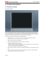
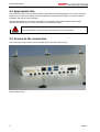
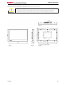
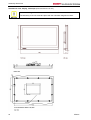
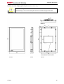
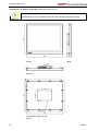
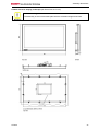
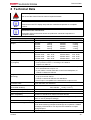
Installation and Operating instructions for
CP29xx
Multi-touch built-in Control Panel with
DVI/ USB Extended interface
Version: 1.4
Date:
2013-12-19
Table of contents
Table of contents
1 Foreword
1.1
3
Notes on the Documentation
3
1.1.1
Liability Conditions
3
1.1.2
Trademarks
3
1.1.3
Patent Pending
3
1.1.4
Copyright
3
1.1.5
State at Delivery
3
1.1.6
Delivery conditions
3
1.2
Description of safety symbols
4
1.3
Basic safety measures
5
1.4
Operator’s obligation to exercise diligence
6
1.4.1
National regulations
6
1.4.2
Procedure in the event of a fault
6
1.4.3
Operator requirements
6
2 Product Description
7
2.1
Product overview
7
2.2
Appropriate Use
8
2.3
Access to the connectors
8
2.4
Interfaces
9
2.4.1
DVI-E Input (Digital Visual Interface-Extended) (X106)
9
2.4.2
USB-Extended Input (X 105)
10
2.4.3
USB in (X 104)
10
2.4.4
USB out (X 102, X 103)
10
2.4.5
Ground connection
10
2.4.6
Power Supply (X101)
10
2.5
Connection Kits/ Connection Cables
11
2.5.1
11
Connection Kits for DVI-E/ USB-E connection, optional
3 Installation
3.1
Transport and Unpacking
12
3.1.1
Transport
12
3.1.2
Unpacking
12
4 Mounting
4.1
CP29xx
12
13
Installation in the control cabinet
13
4.1.1
Preparation of the control cabinet
13
4.1.2
Installation in a control cabinet wall
13
4.1.3
Earthing measures
13
1
Table of contents
4.2
4.1.4
Mounting of the Control Panel
14
4.1.5
Fitting the power supply cable
15
Connecting the Control Panel
16
4.2.1
Connecting cables
16
4.2.2
Protective Earthing
16
5 Operating Instructions
5.1
5.2
5.3
17
Switching the Control Panel on and off
17
5.1.1
Switching on
17
5.1.2
Shutting down and switching off
17
Operation
17
5.2.1
17
Setting the transmission rate
Servicing and maintenance
18
5.3.1
Cleaning
18
5.3.2
Maintenance
18
5.4
Emergency procedures
18
5.5
Shutting down
18
5.5.1
18
Disposal
6 Troubleshooting
19
7 Assembly dimensions
20
8 Technical Data
29
9 Appendix
30
9.1
2
Beckhoff Support and Service
30
9.1.1
Beckhoff branches and partner companies
30
9.1.2
Beckhoff company headquarters
30
9.2
Approvals for USA and Canada
31
9.3
FCC Approvals for the United States of America
31
9.4
FCC Approval for Canada
31
CP29xx
Foreword
1 Foreword
1.1 Notes on the Documentation
This description is only intended for the use of trained specialists in control and automation engineering
who are familiar with the applicable national standards. It is essential that the following notes and
explanations are followed when installing and commissioning these components.
The responsible staff must ensure that the application or use of the products described satisfy all the
requirements for safety, including all the relevant laws, regulations, guidelines and standards.
1.1.1 Liability Conditions
The documentation has been prepared with care. The products described are, however, constantly under
development. For that reason the documentation is not in every case checked for consistency with
performance data, standards or other characteristics. In the event that it contains technical or editorial
errors, we retain the right to make alterations at any time and without warning. No claims for the
modification of products that have already been supplied may be made on the basis of the data, diagrams
and descriptions in this documentation.
1.1.2 Trademarks
Beckhoff®, TwinCAT®, EtherCAT®, Safety over EtherCAT®, TwinSAFE® and XFC® are registered
trademarks of and licensed by Beckhoff Automation GmbH.
Other designations used in this publication may be trademarks whose use by third parties for their own
purposes could violate the rights of the owners.
1.1.3 Patent Pending
The EtherCAT Technology is covered, including but not limited to the following patent applications and
patents: EP1590927, EP1789857, DE102004044764, DE102007017835 with corresponding applications
or registrations in various other countries.
The TwinCAT Technology is covered, including but not limited to the following patent applications and
patents: EP0851348, US6167425 with corresponding applications or registrations in various other
countries.
1.1.4 Copyright
©
Beckhoff Automation GmbH.
The reproduction, distribution and utilization of this document as well as the communication of its contents
to others without express authorization are prohibited. Offenders will be held liable for the payment of
damages. All rights reserved in the event of the grant of a patent, utility model or design.
1.1.5 State at Delivery
All the components are supplied in particular hardware and software configurations appropriate for the
application. Modifications to hardware or software configurations other than those described in the
documentation are not permitted, and nullify the liability of Beckhoff Automation GmbH.
1.1.6 Delivery conditions
In addition, the general delivery conditions of the company Beckhoff Automation GmbH apply.
CP29xx
3
Foreword
1.2 Description of safety symbols
The following safety symbols are used in this operating manual. They are intended to alert the reader to
the associated safety instructions.
Acute risk of injury!
DANGER
If you do not adhere the safety advise adjoining this symbol, there is immediate
danger to life and health of individuals!
Risk of injury!
WARNING
If you do not adhere the safety advise adjoining this symbol, there is danger to life and
health of individuals!
Hazard to individuals!
CAUTION
If you do not adhere the safety advise adjoining this symbol, there is obvious hazard to
individuals!
Hazard to devices and environment
Attention
If you do not adhere the notice adjoining this symbol, there is obvious hazard to
materials and environment.
Note or pointer
This symbol indicates information that contributes to better understanding.
Note
4
CP29xx
Foreword
1.3 Basic safety measures
Before the Industrial PC is switched off, software that is running must be properly closed.
Otherwise it is possible that data on the storage medium is lost. Please read the section Switching the
Control Panel on and off.
Switch off all parts of the equipment, then uncouple the Control Panel
Warning
Before opening the housing, and whenever the Control Panel is not being used for
control purposes (such as during functional checks after a repair), all parts of the
equipment must first be switched off, after which the Control Panel is to be
disconnected from the equipment.
Disconnect the device by unplugging the connectors on the rear side of the Control Panel.
Items of equipment that have been switched off must be secured against being switched on again.
Do not exchange any parts when under power
Warning
When components are being fitted or removed, the supply voltage must be switched
off.
Fitting work on the Control Panel can result in damage:
• if metal objects such as screws or tools fall onto operating circuit boards
• if connecting cables internal to the Panel PC are removed or inserted during
operation.
CP29xx
5
Foreword
1.4 Operator’s obligation to exercise diligence
The operator must ensure that
•
the product is only used as intended (see chapter Product Description)
•
the product is in a sound condition and in working order during operation
•
the product is operated, maintained and repaired only by suitably qualified and authorized
personnel
•
the personnel is instructed regularly about relevant occupational safety and environmental
protection aspects, and is familiar with the operating manual and in particular the safety notes
contained herein
•
the operation manual is in good condition and complete, and always available for reference at the
location of the product.
Do not open the housing of the Control Panel!
For technical support contact Beckhoff Service.
Note
1.4.1 National regulations
Depending on the type of machine and plant in which the Control Panel is used, national regulations
governing the controllers of such machines will apply, and must be observed by the operator. These
regulations cover, amongst other things, the intervals between inspections of the controller. The operator
must initiate such inspections in good time.
1.4.2 Procedure in the event of a fault
In the event of faults at the Control Panel, the list in the section Troubleshooting can be used to determine
the measures to be taken.
1.4.3 Operator requirements
Anyone who uses the Control Panel must have read these operating instructions and must be familiar
with all the functions of the software installed on the Industrial PC to which he has access.
6
CP29xx
Product Description
2 Product Description
2.1 Product overview
Front view of CP29xx
The new Beckhoff panel generation with industry-standard multi-touch display offers a feature-laden
solution for any application. The wide selection of models offers different display sizes and formats as
well as custom designs. Even for single-touch users, this new panel generation offers an excellent priceto-performance ratio and represents an economical alternative to other systems.
The multi-touch built-in Control Panel offer the following benefits:
•
display sizes from 7-inch to 24-inch (16:9, 5:4, 4:3), landscape and portrait orientation
•
multi-touch (PCT): e.g. for 5-finger or 2-hand touch operation
•
high touch-point density for safe operation
•
aluminium housing with glass front, front side IP65, rear side IP20
•
integrated DVI/USB extension technology:
– DVI-E and USB-E 2.0 enable remote panel operation at a distance of up to 50 m from the PC
– USB-E 2.0 transmits USB 2.0 with 480 Mbit/s
– DVI-E input is compatible to the standard DVI output of a PC
•
USB 3.0 input for the direct connection to a standard USB output of a PC with distances of up to
3m
•
2-port USB 3.0 socket inside the Control Panel backplane, for USB-E 2.0 limited to USB 2.0
•
optional electromechanical push-button extension.
CP29xx
7
Product Description
2.2 Appropriate Use
The multi-touch built-in Control Panel CP29xx is designed for industrial application in machine and plant
engineering. A multi-touch display is accommodated in a stainless steel housing. The Control Panel is
installed in the front of control cabinets.
The DVI/USB extension technology integrated in the CP29xx Control Panel enables remote Panel
operation at a distance of up to 50 m from the PC via a standard cable.
Risk of explosion!
The Control Panel must not be used where there is a risk of explosion.
Danger
2.3 Access to the connectors
The connectors of the Control Panel are located at the rear side of the housing.
Picture: Bottom view
8
CP29xx
Product Description
2.4 Interfaces
X106
DVI-E Input
X105
USB-E
Input
X104
USB in
X102,
Ground
X103
USB out
X101
Power
2.4.1 DVI-E Input (Digital Visual Interface-Extended) (X106)
X106
DVI-D 3 X 8-pole digital PCB installation (MOLEX 74320-9000 / 74320-9004)
The DVI-E connection (X 106) is used for transferring the video signal from the Industrial PC to the
Control Panel.
The graphics signal is transferred directly via a DVI cable over a distance of 50 m max. Such a cable
length leads to strong distortion of the graphics signal on arrival at the Control Panel. The CP29xx Control
Panel features a signal processor that restores the DVI signal. The PC requires a conventional DVI
output.
The transmission rate of the DDC file has to be limited
At large distance between PC and Control Panel, the transmission rate of the DDC file
has to be limited.
Note
See also chapter Setting the transmission rate.
Pin
Signal
Pin
Signal
1
Rx2-
13
Rx3+
2
Rx2-
14
+ 5V DVI
3
GND
15
GND
4
Rx4-
16
HPD
5
Rx4+
17
Rx0-
6
DDC CLK
18
Rx0+
7
DDC DAT
19
GND
8
AV SYNC
20
Rx5-
9
Rx1-
21
Rx5+
10
Rx1+
22
GND
11
GND
23
RxC+
12
Rx3-
24
RxC-
CP29xx
9
Product Description
2.4.2 USB-Extended Input (X 105)
X105
Connection via standard-RJ45-cabel, not crossed
The Control Panel is connected with the CU8801 USB to USB extended converter box via the USBExtended input (X 105).
In order to realize a distance of 50 m without hubs, with USB extended the USB signal is converted so
that it can be transferred via 50 m CAT5 cables commonly used for Ethernet wiring. In the Control Panel
the signal is converted back to USB.
2.4.3 USB in (X 104)
X104
USB type B, PCB installation (FCI 61729-0010B USB Receptacle B-Type)
The Control Panel is connected with the Industrial PC via the USB port (X 104, connector type B).
USB3.0 standard is supported.
Pin
Signal
Pin
Signal
1
5V
3
D+
2
D-
4
GND
2.4.4 USB out (X 102, X 103)
X102, X103
USB Type-A twin circuit board mounting (FCI 72309-0030B USB Double Receptacle A-Type)
The two USB interfaces (X102, X103, connector type A) are used for connecting peripheral devices with
USB connection. USB3.0 standard is supported in a distance of up to 5 m from the PC, from a distance of
5 m up to 50 m USB2.0 standard is supported.
Pin
Signal
Pin
Signal
1
5V
3
D+
2
D-
4
GND
2.4.5 Ground connection
The Control Panel is grounded via the screw connection (Ground).
2.4.6 Power Supply (X101)
X101
Socket 5-pol RM3.50 Sw Screw Clamp BL3.5/180F (WEIDMÜLLER 1615810000)
The power supply for the Control Panel is established via the socket (X101). The power supply connector
is included in delivery.
Pin
Signal
Pin
Signal
1
NC
4
GND
2
NC
5
+ 24 VDC
Power Supply
3
10
CP29xx
Product Description
2.5 Connection Kits/ Connection Cables
One 5-pole power supply connector is provided with the Control Panel.
Optionally prefabricated connection kits for the DVI-E/ USB-E connection are available.
2.5.1 Connection Kits for DVI-E/ USB-E connection, optional
The following connection kits are available:
Connecting kit
DVI-E/ USB-E Connection
C9900-K622
Connecting kit 1 m for CP29xx, containing:
1 m DVI cable, 1 m USB cable
C9900-K623
Connecting kit 3 m for CP29xx, containing:
3 m DVI cable, 3 m USB cable
C9900-K624
Connecting kit 5 m for CP29xx, containing:
5 m DVI cable, 5 m USB cable
C9900-K625
Connecting kit 10 m for CP29xx, containing:
10 m DVI cable, 10 m CAT 5 cable for USB-E-2.0, USB to USB-E-2.0 converter
CU8801 for mounting rail installation close to the PC and 1 m USB cable to connect
the USB to USB-E-2.0 converter to the PC
C9900-K626
Connecting kit 20 m for CP29xx, containing:
20 m DVI cable, 20 m CAT 5 cable for USB-E-2.0, USB to USB-E-2.0 converter
CU8801 for mounting rail installation close to the PC and 1 m USB cable to connect
the USB to USB-E-2.0 converter to the PC
C9900-K627
Connecting kit 30 m for CP29xx, containing:
30 m DVI cable, 30 m CAT 5 cable for USB-E-2.0, USB to USB-E-2.0 converter
CU8801 for mounting rail installation close to the PC and 1 m USB cable to connect
the USB to USB-E-2.0 converter to the PC
C9900-K628
Connecting kit 40 m for CP29xx, containing:
40 m DVI cable, 40 m CAT 5 cable for USB-E-2.0, USB to USB-E-2.0 converter
CU8801 for mounting rail installation close to the PC and 1 m USB cable to connect
the USB to USB-E-2.0 converter to the PC
C9900-K629
Connecting kit 50 m for CP29xx, containing:
50 m DVI cable, 50 m CAT 5 cable for USB-E-2.0, USB to USB-E-2.0 converter
CU8801 for mounting rail installation close to the PC and 1 m USB cable to connect
the USB to USB-E-2.0 converter to the PC
CP29xx
11
Installation
3 Installation
3.1 Transport and Unpacking
The specified storage conditions must be observed (see chapter Technical Data).
3.1.1 Transport
Despite the robust design of the unit, the components are sensitive to strong vibrations and impacts.
During transport, your Control Panel should therefore be protected from excessive mechanical stress.
Therefore, please use the original packaging.
Danger of damage to the unit
Attention
If the device is transported in cold weather or is exposed to extreme variations in
temperature, make sure that moisture (condensation) does not form on or inside the
device.
Prior to operation, the unit must be allowed to slowly adjust to room temperature. Should condensation
occur, a delay time of approximately 12 hours must be allowed before the unit is switched on.
3.1.2 Unpacking
Proceed as follows to unpack the unit:
1. Remove packaging.
2. Do not discard the original packaging. Keep it for future relocation.
3. Check the delivery for completeness by comparing it with your order.
4. Please keep the associated paperwork. It contains important information for handling the unit.
5. Check the contents for visible shipping damage.
If you notice any shipping damage or inconsistencies between the contents and your order, you should
notify Beckhoff Service.
12
CP29xx
Mounting
4 Mounting
The Control Panel CP29xx is designed for mounting in control cabinets in machine and plant engineering
applications. The ambient conditions specified for operation must be observed (see chapter Technical
Data).
4.1 Installation in the control cabinet
4.1.1 Preparation of the control cabinet
The control cabinet wall must be prepared with the required mounting opening according to the Control
Panel’s dimensions (see chapter Assembly dimensions).
Circulation of air
Note
When the unit is installed in an enclosure, adequate space for ventilation must be
provided.
The clearance above and below the housing must be at least 5 cm in order to ensure
adequate ventilation of the Control Panel.
Please note the following points during installation of the Control Panel:
• Position the Control Panel in such a way that reflections on the screen are avoided as far as possible.
• Use the position of the screen as a guide for the correct installation height; it should be optimally
visible for the user at all times.
• The Control Panel should not be exposed to direct sunlight.
• When the unit is in its mounting position, the ventilation openings must not be obstructed.
Avoid extreme environmental conditions
Attention
Extreme environmental conditions should be avoided as far as possible. Protect the
Control Panel from dust, moisture and heat.
The ventilation slots of the Control Panel must not be covered.
4.1.2 Installation in a control cabinet wall
For installation of the Control Panel proceed as follows:
1. Insert the Control Panel at the intended control cabinet wall position and protect it from falling out,
prior to final mounting.
2. Release the clamping levers, turn the clamping levers to the side and retighten the screws (see
chapter Mounting of the Control Panel).
4.1.3 Earthing measures
Earthing connections dissipate interference from external power supply cables, signal cables or cables to
peripheral equipment. Establish a low-impedance connection from the earthing point on the Control Panel
housing (see chapter Ground connection) to the central earthing point on the control cabinet wall, in
which the Panel is being installed.
CP29xx
13
Mounting
4.1.4
Mounting of the Control Panel
The Control Panel is installed in the cabinet wall with clamping levers. For the cutout dimension of the
Control Panel see chapter Assembly dimensions, the wall thickness is between 1 mm and 5 mm.
1. Insert the Control Panel into the cutout.
2. Release the clamping levers with a 3.0 mm Allen key.
3. Turn the clamping levers to the side through 90°.
4. Retighten the screws.
14
CP29xx
Mounting
4.1.5 Fitting the power supply cable
Fit the cables for the power supply of the Control Panel, using the included material for assembling the
connectors:
Material for assembling
the connector
Plug connector 5-pole
Stain relief housing with lacing cord
Conductive cross-section
The connector is specified for 16 A and can lift conductive cross-sections until 1.5 mm2.
Note
So the connector is fitted to the cable
1. Strip insulation from the cable ends (Length of stripped conductor is 8 - 9 mm).
2. Screw together the cable ends in the 5-pole plug connector in accordance with wiring diagram.
Applying the strain relief
Thread the lacing cord into that lower part of the stain relief
housing.
Putting in the plug connector
Put the plug connector into that lower part of the stain relief
housing.
Tighten the lacing cord and pinch off the plastic strap.
Fixing the upper part of the stain relief housing
Fix the upper part of the stain relief housing by snapping it onto
the lower part.
CP29xx
15
Mounting
4.2 Connecting the Control Panel
Risk of explosion!
Danger
The Control Panel must never be connected or disconnected in an area that is subject to
explosion hazard!
The mains plug must be disconnected
Please read the documentation for the external devices prior to connecting them!
Attention
During thunderstorms, plug connector must neither be inserted nor removed!
When disconnecting a plug connector, always handle it at the plug. Do not pull the cable!
4.2.1 Connecting cables
The connections are located at the rear of the Control Panel and are documented in the chapter
Interfaces.
When connecting cables to the Control Panel, please adhere to the following order:
•
Disconnect the Control Panel from the power supply.
•
Connect all cables at the Control Panel and at the devices to be connected.
•
Ensure that all screw connections between connectors and sockets are tight!
•
Reconnect all devices to the power supply.
4.2.2 Protective Earthing
The low resistance protective earthing connection of the Control Panel is established via the screw
connection, which is located in the connection area.
16
CP29xx
Operating Instructions
5 Operating Instructions
5.1 Switching the Control Panel on and off
5.1.1 Switching on
The Control Panel does not have its own mains power switch. As soon as the power supply is switched
on the Control Panel is activated.
5.1.2 Shutting down and switching off
Control software such as is typically used on Industrial PCs permits various users to be given different
rights. A user who may not close software may also not switch the Industrial PC off, since data can be
lost from the storage medium by switching off while software is running.
First shut down, then switch off!
Warning
If the Industrial PC is switched off as the software is writing a file to the storage
medium, the file will be destroyed. Control software typically writes something to the
storage medium every few seconds, so that the probability of causing damage by
switching off while the software is running is very high.
Switch off power supply
Warning
When you have shut down the Industrial PC, you have to switch off power supply for at
least 10 seconds before rebooting the system.
After resetting power supply the Industrial PC will start booting automatically.
5.2 Operation
The operation of the Control Panel occurs via the Touch Screen.
Risk of damaging the Touch Screen
Warning
The touch screen may only be actuated by finger tips or with the touch screen pen. The
operator may wear gloves but there must be no hard particles such as metal shavings,
glass splinters embedded in the glove.
5.2.1 Setting the transmission rate
At large distance between PC and Control Panel, the transmission rate of the DDC file has to be limited.
The DDC file is transmitted from the Control Panel to the PC in order to transfer the display information
like timing and resolution.
The video bios of the graphic card or, using the on-board graphic, the video bios of the motherboard
contains the definition of the transmission rate for the DDC file. This value has to be 50 kHz or less.
Otherwise the screen is not displayed or not until windows is started.
Windows graphic drivers also include a value for the transmission rate of the DDC file.
If Windows is running and no image is displayed, then use a graphic driver with a value of 50 kHz or less
for DDC file transmission.
CP29xx
17
Operating Instructions
5.3 Servicing and maintenance
5.3.1 Cleaning
Disconnect power supply
DANGER
Switch off the device and all connected devices, and disconnect the device from the
power supply.
The device can be cleaned with a soft, damp cleaning cloth. Do not use any aggressive cleaning
materials, thinners, scouring material or hard objects that could cause scratches.
5.3.2 Maintenance
The Control Panel is maintenance-free.
5.4 Emergency procedures
In case of fire, the Control Panel should be extinguished with powder or nitrogen.
5.5 Shutting down
5.5.1 Disposal
Observe national electronics scrap regulations
Observe the national electronics scrap regulations when disposing of the device.
Note
In order to dispose of the device, it must be removed and fully dismantled:
18
•
Housing components (polycarbonate, polyamide (PA6.6)) are suitable for plastic recycling.
•
Metal parts can be sent for metal recycling.
•
Electronic parts such as disk drives and circuit boards must be disposed of in accordance with
national electronics scrap regulations.
CP29xx
Troubleshooting
6 Troubleshooting
Pixel errors
Note
Pixel errors in the TFT display are production-caused and represent no complaintreason!
Anomalies of the Touchscreen
Note
Anomalies of the touchscreen sensor are production-caused and represent no
complaint-reason!
Fault
Cause
Measures
The Control Panel shows no
function
No power supply to the Control
Panel/ Industrial PC
Check power supply cable
Cable not connected
1.
2.
Correctly connect cable
Call Beckhoff Service
Computer boots, software starts,
but control does not operate
correctly
Cause of the fault is either in the
software or in parts of the plant
outside the Industrial PC
Call the manufacturer of the
machine or the software
No screen
Transmission rate is too high when
using DVI cables longer than 20 m
Limit transmission rate for
DDC file to 50 kHz
USB error while TwinCAT access
via USB
Cycle time in TwinCAT is set on
10 ms (standard)
Increase the cycle time up to
50 ms till 80 ms
The Control Panel functions only
Faulty backlight in the display
partially or only part of the time, e.g.
Defective components in the
no or dark picture
Control Panel
CP29xx
Call Beckhoff Service
Call Beckhoff Service
19
Assembly dimensions
7 Assembly dimensions
CP2907 with 7“ display, landscape (all dimensions are in mm)
Notice mounting orientation
The assembly of the unit must take place with the orientation diagrammed here.
Warning
CP2912 with 12“ display, landscape (all dimensions are in mm)
20
CP29xx
Assembly dimensions
CP2915 with 15“ display, landscape (all dimensions are in mm)
Notice mounting orientation
The assembly of the unit must take place with the orientation diagrammed here.
Warning
CP29xx
21
Assembly dimensions
CP2915 with 15“ display, portrait (all dimensions are in mm)
Notice mounting orientation
The assembly of the unit must take place with the orientation diagrammed here.
Warning
22
CP29xx
Assembly dimensions
CP2916 with 15.6“ display, landscape (all dimensions are in mm)
Notice mounting orientation
The assembly of the unit must take place with the orientation diagrammed here.
Warning
CP29xx
23
Assembly dimensions
CP2918 with 18.5“ display, landscape (all dimensions are in mm)
Notice mounting orientation
The assembly of the unit must take place with the orientation diagrammed here.
Warning
24
CP29xx
Assembly dimensions
CP2918 with 18.5“ display, portrait (all dimensions are in mm)
Notice mounting orientation
The assembly of the unit must take place with the orientation diagrammed here.
Warning
CP29xx
25
Assembly dimensions
CP2919 with 19“ display, landscape (all dimensions are in mm)
Notice mounting orientation
The assembly of the unit must take place with the orientation diagrammed here.
Warning
26
CP29xx
Assembly dimensions
CP2921 with 21.5“ display, landscape (all dimensions are in mm)
Notice mounting orientation
The assembly of the unit must take place with the orientation diagrammed here.
Warning
CP29xx
27
Assembly dimensions
CP2924 with 24“ display, landscape (all dimensions are in mm)
Notice mounting orientation
The assembly of the unit must take place with the orientation diagrammed here.
Warning
28
CP29xx
Technical Data
8 Technical Data
Risk of explosion!
Do not use the Control Panel in areas of explosive hazard!
Danger
Pixel errors
Note
Pixel errors in the TFT display are production-caused and represent no complaintreason!
Anomalies of the Touchscreen
Note
Anomalies of the touchscreen sensor are production-caused and represent no
complaint-reason!
Product name
CP29xx
Dimensions (B x H x T)
See chapter Assembly dimensions
Weight
CP2907:
CP2912:
CP2915:
CP2916:
Supply voltage
24 VDC (20.4 – 28.8 VDC)
Power consumption
CP2907-0000:
CP2912-0000:
CP2915-0000:
CP2916-0000:
UL-compliance
(in progress)
• Using a power supply class 2 or
Interfaces
• USB 3.0 input for the direct connection to a standard USB output of
a PC with distances of up to 3 m
1.46 kg
2.95 kg
3.64 kg
4.22 kg
max. 12 W
max. 16 W
max. 20 W
max. 22 W
CP2918:
CP2919:
CP2921:
CP2924:
CP2918-0000:
CP2919-0000:
CP2921-0000:
CP2924-0000:
5.10 kg
5.36 kg
5.90 kg
7.18 kg
max. 25 W
max. 25 W
max. 35 W
max. 45 W
• Fuse protection with 4 A, according to UL 60950.2
chapter 2.5, table 2C
• 2-port USB 3.0 socket inside the Control Panel backplane, for
USB-E 2.0 limited to USB 2.0
Integrated DVI/USB extension
technology
• DVI-E and USB-E 2.0 enable remote panel operation at a distance
of up to 50 m from the PC
• USB-E 2.0 transmits USB 2.0 with 480 Mbit/s
• DVI-E input is compatible to the standard DVI output of a PC
Protection class
Front side IP65, rear side IP20
Shock resistance
(Sinusoidal vibration)
EN 60068-2-6:
10 to 58 Hz:
58 to 500 Hz:
Shock resistance (Shock)
EN 60068-2-27:
5 G (~ 50 m/ s2), duration: 30 ms
EMC compatibility
Resistance to interference conforms to EN 61000-6-2
EMC compatibility
Emission of interference conforms to EN 61000-6-4
Permissible ambient temperature
0°C to +55°C (operation ); CP2924: 0°C to +50°C (operation)
-25°C to +65°C (transport/ storage)
Permissible relative humidity
to 95%, no condensation
Transport and storage
The same values for atmospheric humidity and shock resistance are
to be observed during transport and storage as in operation. Suitable
packaging of the Panel PC can improve the resistance to impact
during transport.
Certifications
CE; UL in progress
CP29xx
0.035 mm
0.5 G (~ 5 m/ s2)
29
Appendix
9 Appendix
9.1 Beckhoff Support and Service
Beckhoff and their partners around the world offer comprehensive support and service, making available
fast and competent assistance with all questions related to Beckhoff products and system solutions.
9.1.1 Beckhoff branches and partner companies
Please contact your Beckhoff branch office or partner company for local support and service on Beckhoff
products!
The contact addresses for your country can be found in the list of Beckhoff branches and partner
companies: www.beckhoff.com. You will also find further documentation for Beckhoff components there.
9.1.2 Beckhoff company headquarters
Beckhoff Automation GmbH
Eiserstraße 5
33415 Verl
Germany
Phone: + 49 (0) 5246/963-0
Fax:
+ 49 (0) 5246/963-198
E-mail:
[email protected]
Web:
http://www.beckhoff.de/
Beckhoff Support
Support offers you comprehensive technical assistance, helping you not only with the application of
individual Beckhoff products, but also with other, wide-ranging services:
• world-wide support
• design, programming and commissioning of complex automation systems
• and extensive training program for Beckhoff system components
Hotline:
Fax:
E-mail:
+ 49 (0) 5246/963-157
+ 49 (0) 5246/963-9157
[email protected]
Beckhoff Service
The Beckhoff Service Center supports you in all matters of after-sales service:
• on-site service
• repair service
• spare parts service
• hotline service
Hotline:
Fax:
E-mail:
+ 49 (0) 5246/963-460
+ 49 (0) 5246/963-479
[email protected]
If servicing is required, please quote the project number of your product.
30
CP29xx
Appendix
9.2 Approvals for USA and Canada
9.3 FCC Approvals for the United States of America
FCC: Federal Communications Commission Radio Frequency Interference Statement
This equipment has been tested and found to comply with the limits for a Class A digital device, pursuant
to Part 15 of the FCC Rules. These limits are designed to provide reasonable protection against harmful
interference when the equipment is operated in a commercial environment. This equipment generates,
uses, and can radiate radio frequency energy and, if not installed and used in accordance with the
instruction manual, may cause harmful interference to radio communications. Operation of this equipment
in a residential area is likely to cause harmful interference in which case the user will be required to
correct the interference at his own expense.
Technical modifications
Technological changes to the device may cause the loss of the FCC approval.
Note
9.4 FCC Approval for Canada
FCC: Canadian Notice
This equipment does not exceed the Class A limits for radiated emissions as described in the Radio
Interference Regulations of the Canadian Department of Communications.
CP29xx
31