1
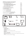
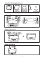
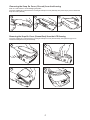
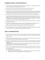
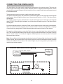
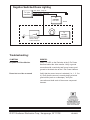
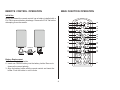
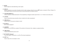
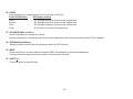
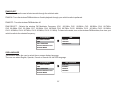
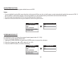
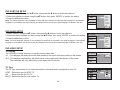
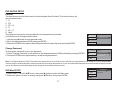
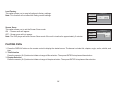
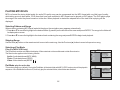
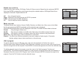
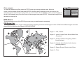
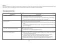
R VOD10A 10.1" OVERHEAD LCD MONITOR WITH DVD PLAYER Installation Guide Important Notice An LCD panel and/or video monitor may be installed in a motor vehicle and visible to the driver if the LCD panel or video monitor is used for vehicle information, system control, rear or side observation or navigation. If the LCD panel or video monitor is used for television reception, video or DVD play, the LCD panel or video monitor must be installed so that these features will only function when the vehicle is in "park" or when the vehicle,s parking brake is applied. An LCD panel or video monitor used for television reception, video or DVD play that operates when the vehicle is in gear or when the parking brake is not applied must be , installed to the rear of the driver s seat where it will not be visible, directly or indirectly, to the operator of the motor vehicle. Installation of overhead products requires careful planning and preparation. Be extremely careful when working on a vehicle with side curtain air bags. Do not route wires near any portion of the side curtain air bag assemblies. This includes any anchor points in A, B, C or D pillars of the vehicle. Routing wires in these areas or running wires by the side curtain air bags can prevent the side curtain air bag from fully deploying which can result in personal injury to vehicle occupants. If you have any questions regarding wire routing in a vehicle, please contact Audiovox Technical Support at 1-800-225-6074. When connecting power and ground in a mobile video installation ensure that the ACC wire is fused at the point where it is connected to the vehicle ACC wiring. Failure to do so can result in damage to the vehicle if a short circuit develops between the vehicle connection point and the mobile video product. Important Note The VOD10A incorporates two new features: 1) A wireless FM Modulator 2) Snap on Covers with matching Trim Rings (Shale and Pewter). Select the color that matches the interior trim. Please be advised that the wireless FM modulator will perform well in most applications. However, in certain applications the quality of the wireless signal may be less than optimal, resulting in static or strong local station bleed through. Licensed under one or more of the following patents, Patent NOS. 5,775,762, 5,927,784 and 6,678,892 2 MATERIALS INCLUDED IN THIS PACKAGE: 1) 10.1” TFT LCD Overhead Monitor With DVD Player 2) Hardware Package (P/N 150-1661) - M3 x 8mm Phillips Screws (P/N 100-2427) - #4 x 5/16" Phillips Self Tapping Screws (P/N 100-2316) - #4 x 7/16" Phillips Self Tapping Screws (P/N 100-2426) - #8 x 3/8" Self Drilling Screws (P/N 100-2397) - M5 x 10mm Phillips Screws (P/N 100-2394) 3) Remote Control (P/N 136-4840) 4) Universal Mounting Bracket (P/N 108-3921) 5) Dome Light Extension Harness (P/N 112-3884) 6) 2 Pin Power Harness (P/N 112-4152) 7) Pry Tool (P/N 100-2424) 8) Screw Cap - Shale (P/N 102-4253) - Pewter (P/N 102-4254) 9) Trim Ring - Shale (P/N 102-4231) - Pewter (P/N 102-4232) 10) Snap On Cover (Screen Back) - Shale (P/N 102-4233) - Pewter (P/N 102-4234) 11) Snap On Cover (Shroud) - Shale (P/N 102-4235) - Pewter (P/N 102-4236) 12) Wireless Headphones (P/N 136-4944) - (1 pc) - (1 pc) - (5 pcs) - (1 pc) - (3 pcs) - (4 pcs) - (4 pcs) - (1 pc) - (1 pc) - (1 pc) - (1 pc) - (1 pc) - (2 pcs) - (2 pcs) - (1 pc) - (1 pc) - (1 pc) - (1 pc) - (1 pc) - (1 pc) - (2 pcs) 1 4 7 10 2 5 8 11 6 9 12 3 POWER EJECT M1 M2 TV DVD SOURCE DVD SOURCE MUTE VOLUME PIX SYSTEM MENU DISC MENU ZOOM SETUP SUBTITLE REPEAT ENTER DISPLAY AUDIO 1 2 3 4 5 6 7 8 FMM ON/OFF 9 0 IRT ON/OFF TOOLS REQUIRED: #2 Phillips Screwdriver #1 Phillips Screwdriver Utility or Razor Knife or Shears Wire Strippers Upholstery hook tool (for removal of panels as necessary) Electrical Tape Masking Tape Multimeter (to verify 12 volt DC and continuity: Do not use a test light or logic probe) Marker pen – to mark headliner Scribe (to mark trim ring if used) Misc. electrical connectors (to connect to vehicle power source). Requirements will vary from vehicle to vehicle) DVD Movie (to verify system operation after installation) 3 Installing the Snap On Covers 1. Housing 2. 3. 4. Snap On Cover (Shroud) 1 Pewter, 1 Shale Snap On Cover (Screen Back Cab) 1 Pewter, 1 Shale Pry Tool 5. Screw Cap (L & R) 2 Pewter, 2 Shale Place the unit on a soft surface to avoid damaging the plastic. Installing the Shroud catch catch Remove tape backing before installing. (A) Begin by hooking area “A” (above) over the dome light and slide the cover over the unit. The cover will snap in place. Installing the Screen Cover (B) (B) Open the screen and hook the two tabs “B” on the bottom edge of the screen. Snap the opposite side over the hinge. Installing the Screw Caps Plug-in Install the screw caps after the unit is mounted. 4 Removing the Snap On Cover (Shroud) from the Housing Work on a soft surface to avoid damaging the plastic. Insert the supplied pry tool between the Housing and Snap On Cover (Shroud), then press the pry tool to release the Snap On Cover (Shroud). 1 2 3 Removing the Snap On Cover (Screen Back) from the LCD Housing Insert the supplied pry tool between the Housing and Snap On Cover (Screen Back), then press the pry tool to release the Snap On Cover (Screen Back). 4 5 6 7 5 GENERAL INSTALLATION APPROACH: 1) Decide upon system configuration and options that will be installed (i.e.: what components, Video Game, external amp, wireless headphones, VCP, etc.). 2) Review all manuals to become familiar with electrical requirements and hook ups. 3) Decide upon mounting locations of all components and method of mounting. 4) Prep the vehicle by removing any interior trim necessary to gain access to vehicle's wiring as well as all areas where interconnecting wire harnesses will need to be located. If any access holes need to be cut into the vehicle (headliner, other trim components etc.), this should be done now as well. 5) Route the wiring harnesses throughout the vehicle as necessary. (Refer to the Wiring Diagrams in this manual as well as the wiring instructions for the individual components and accessory options being installed). Be sure that all wiring is protected from sharp edges and is routed in such a manner that wiring is not pinched when all components and interior trim are fully installed. Be sure to leave enough slack in the wiring at each component to allow working room. 6) Remove all A/V system components from their packaging and place them loosely in the vehicle at their respective locations. 7) Connect all components together (electrically) and verify proper operation of all system functions. Note: This is best done BEFORE the components have been permanently mounted. 8) After verifying proper operation of the system, proceed to mount each component. 9) When all components are mounted, recheck the function of the entire system again to ensure that no wiring was pinched or connected improperly during final installation. VEHICLE PREPARATION: 1) Locate an accessory power source (+12v when the key is in the ACC. and run positions, and 0v when the key is off), and also a good ground. Generally, these wires can be found at the ignition switch or fuse box. 2) The mounting method and location will vary from vehicle to vehicle, so this manual will only focus on the installation of the VOD10A and related console accessories. 3) Generally, the best location for the video monitor is where the vehicle's factory dome light is installed. The monitor should be located in such a manner that it can be comfortably viewed by rear seat passengers. NEVER INSTALL THE MONITOR IN A PLACE WITHIN THE DRIVER'S VIEW. THIS IS NOT ONLY DANGEROUS, BUT IT IS ALSO ILLEGAL IN MANY STATES. 4) Once the mounting location of the monitor has been determined, additional preparation work may be necessary, depending on the vehicle’s structure and installation method. Some of the steps that may be required are: A) Removal of the vehicle's dome light. B) If the trim ring will be used, it may have to be trimmed to fit the contour of the vehicle's headliner. Refer to the "Trim Ring Installation" section in this manual. 6 GENERAL SYSTEM CONFIGURATIONS: The following is intended to provide some of the system configurations that are possible with the VOD10A Drop Down Video Systems: The VOD10A has an option that allows the user to select from two IR transmit and receive codes (M1 or M2). This feature can be used when using two VOD10As in the same installation or if the vehicle has an RSA (Rear Seat Audio) that uses an “A” channel headset. The VOD10A comes factory set to M1. When in the M1 mode the unit will respond to remote commands when M1 is selected on the remote and will transmit audio on the A channel. When in the M2 mode the unit will respond to remote commands when M2 is selected on the remote and will transmit audio on the B channel. Note: M1 will appear on the screen for 4~5 seconds. Selecting a Monitor Code (M1 or M2) 1. Power ON the unit and wait until M1 on the OSD appears. M1 will appear on the screen for 4~5 seconds. After M1 disappears, within 10 seconds press the M1 button on the remote control, then press the TV button and continue to press code number 6353. The screen will change from M1 to M2. 2. To change the monitor code from M2 to M1, repeat the above instruction but press the M2 button, then the TV button, then 6353. 3. The selected mode (M1 or M2) will be retained in memory until changed by the user. FMM 88.3MHz AUX/GAME FMM OFF M1 DVD M2 IRT ON IRT OFF Notes: There are a few options that can be added as follows: The VOD10A video system is only intended for an overhead, drop down installation. It is not intended for Seatback or any other type of mounting. The hinging mechanism is designed for horizontal, drop down use only. The two pods can be connected together using the RCA cables plugged into the AV1 Input RCAs on one pod and plugging the RCA connectors into the AV out RCA connectors on the other pod. 7 TRIM RING INSTALLATION: Note: This page only covers special installation considerations for thick trim ring installation. If the video monitor is to be installed in a vehicle with the thick trim ring, it may need to be trimmed to fit the contour of the vehicle Headliner. Note: The trim rings supplied with this unit are not designed to be trimmed. 1) In this installation, the video monitor is mounted directly to the overhead cross-member in the roof using the mounting screw bosses. These screw bosses should contact the cross-member directly (i.e.: no gap between the screw boss and the roof structure). Also, be sure that the screws do not pierce the outer roof skin when fully fastened to the cross-member. The trim ring is attached to the video monitor using the perimeter screw bosses. It is important that the screws used in this installation are not over tightened, and that the video monitor and trim ring are mounted in such a way that the assembly does not distort (or bend) when the mounting screws are tightened. An alternate method is to use the mounting bracket. First secure the mounting bracket to the crossmember, then screw the monitor into the mounting bracket. See the drawing in this manual. 2) It is best to mount the video monitor to the roof structure without the trim ring first. There should be a gap between the headliner and the outer flange of the video monitor. The trim ring should be cut to fill this gap. Apply masking tape to the outer surface of the trim ring in the areas where the cut will be made. 3) Mark the cut to follow the necessary contour of the roof. The suggested method of marking is as follows: A) First mark the narrowest point of the trim ring on the masking tape. Be careful to consider not only the vertical location, but the fore-aft location. B) Using the handle of a screwdriver, make a “transfer marking tool”. See the diagram below. Place the tool against the roof and the marker against the masking tape on the trim ring. Trace the cut to be made around the entire perimeter of the trim ring. C) Cut the trim ring using a sharp utility knife or shears. Make the cut in several passes over the marked line, each time cutting a little deeper. It is not necessary to cut completely through the plastic, the cut only need be over 50% of the wall thickness of the plastic. By bending the cut back and forth several times, the plastic will break cleanly at the cut. D) Check the fit of the trimmed console and make any minor adjustments necessary. 4) The trim ring can be painted or covered with a material that matches the headliner before assembling the trim ring to video monitor. 5) The finished trim ring should be attached to the video monitor, then attach the assembly to the roof. Headliner Cut line Lowest point mark Tape marker to screwdriver. Starting at your mark for the lowest point, trace the contour of the roof 8 TRIM RING INSTALLATION: To install the Trim Ring to the unit, use the supplied screws listed below: A) #4 x 5/16 Phillips Self Tapping Screws (1 pc) B) #4 x 7/16 Phillips Self Tapping Screws (3 pcs) C) M3 x 8mm Phillips Screws (5 pcs) Please see the illustration below for screw locations. A B C C C B C C B MOUNTING THE TRIM RING: Roof Roof Support Headliner Mounting Bracket Self-drilling Screws Trim Ring Video Unit M5 Screw 9 WIRING DIAGRAM Dome Light Power source Line In-R (Red) Line In-V (Yellow) 10 Pin A/V In Out Harness Dome Light Extension Harness (P/N 112-3884) Power Supply Harness Line Out-V (Yellow) Line In-L (White) Line Out-L (White) Line Out-R (Red) 2 Pin Power Harness (P/N 112-4152) * Antenna for Wireless FM Mod. ** See Antenna Note 1) Make the connections to the vehicle for the 10 pin wiring harness. 2) Connect the 2 Pin Power Harness to the vehicle’s electrical system by tapping into an accessory hot line and a good ground. 3) Verify all system functions before final mounting of the finished assembly. A/V Source Definitions: 1. DVD - Built in DVD. 2. AV1 - Signal Harness to the 3 RCA Jack Pigtail is used for AV1 input. 3. AUX - AUX input. *NOTE: Extending the wireless antenna will cause the FM modulator to exceed FCC limits of wireless transmission. When installing the unit, position the antenna for best reception. 10 CONNECTING THE DOME LIGHTS: The dome lights in the video monitor require three connections to the vehicle's wiring. There are two common types of dome light circuits: positive switched systems or negative switched systems. Positive switched systems supply voltage to the interior lights to turn on; negative switched systems apply ground to illuminate the bulbs. To determine which system you have, locate the wires at the dome light: On a positive switched system, with all the doors closed and the lights out, both wires at the dome light will rest at ground. When the light is activated, one of these wires will switch to +12 VDC. This is the vehicle's switching wire. On a negative switched system, with all the doors closed and the lights out, both wires at the dome light will rest at +12 VDC. When the light is activated, one of these wires will switch to ground. This is the vehicle’s switching wire. For positive switched systems, connect the Purple / brown (Lamp Auto) wire to the vehicle's switched wire. Then connect the Red / black (Lamp On) wire to a fused constant 12 volt source and the Black / red (Lamp Common) wire to a good ground. Positive switched systems are commonly found on Ford vehicles. For negative switched systems, connect the Purple / brown (Lamp Auto) wire to the vehicle's switched wire. Then connect the Red / black (Lamp On) wire to a good ground and the Black / red (Lamp Common) wire to a fused constant 12 volt source. Negative switched systems are commonly found on General Motors and import vehicles. Note: Some vehicles which incorporate transistorized control of the dome light circuit, such as the 1999 Dodge Caravan, may require that the Purple / brown (Lamp Auto) wire be connected to the door pin switch wire, as the additional current draw of the monitor's lights may not be supported by the output of the vehicle’s body control computer. Positive Switched Dome Lighting To 3 pin connector on Monitor Red / black - Lamp On Black / red - Lamp Common Purple / brown - Lamp Auto To constant +12 VDC Fused Factory Dome Light Circuit To constant +12 VDC Factory Door Ajar Switch or Body Control Computer 11 Negative Switched Dome Lighting To 3 pin connector Red / black - Lamp On Black / red - Lamp Common Purple / brown - Lamp Auto To constant +12 VDC Fused To constant +12 VDC Factory Door Ajar Switch or Body Control Computer Troubleshooting: SYMPTOM: REMEDY: No power at Video Monitor Verify +12 VDC on the Red wire at the 2 Pin Power Harness behind the video monitor. Verify a ground connection with a continuity test from a known good ground to the black wire at the 2 Pin Power Harness. Power but no video or sound Verify that the correct source is selected (i.e.: 1, 2, 3 or 4). Verify that the source is on and playing a known good media (such as a videotape). Verify the connections at both ends of the source component harness. © 2011 Audiovox Electronics Corp., Hauppauge, NY 11788 128-8932 VOD10A 10.1" OVERHEAD LCD MONITOR WITH DVD PLAYER OPERATION MANUAL 128-8931 Important Notice Installation of overhead products requires careful planning and preparation. Be extremely careful when working on a vehicle with side curtain air bags. Do not route wires near any portion of the side curtain air bag assemblies. This includes any anchor points in A, B, C or D pillars of the vehicle. Routing wires in these areas or running wires by the side curtain air bags can prevent the side curtain air bag from fully deploying which can result in personal injury to vehicle occupants. If you have any questions regarding wire routing in a vehicle, please contact Audiovox Technical Support at 1-800-225-6074. When connecting power and ground in a mobile video installation ensure that the ACC wire is fused at the point where it is connected to the vehicle ACC wiring. Failure to do so can result in damage to the vehicle if a short circuit develops between the vehicle connection point and the mobile video product. An LCD panel and/or video monitor may be installed in a motor vehicle and visible to the driver if the LCD panel or video monitor is used for vehicle information, system control, rear or side observation or navigation. If the LCD panel or video monitor is used for television reception, video or DVD play, the LCD panel or video monitor must be installed so that these features will only function when the vehicle is in “park” or when the vehicle's parking brake is applied. An LCD panel or video monitor used for television reception, video or DVD play that operates when the vehicle is in gear or when the parking brake is not applied must be installed to the rear of the driver's seat where it will not be visible, directly or indirectly, to the operator of the motor vehicle. Warnings • Do not use any solvents or cleaning materials when cleaning the video monitor. • Do not use any abrasive cleaners, they may scratch the screen. • Use only a lightly dampened lint free cloth to wipe the screen if it is dirty. • Lock the LCD screen in the fully closed position when not in use. • Before putting on headphones always adjust the volume setting to the lowest position. • Remember to leave the dome light switch in the OFF or AUTO positions when the vehicle is unattended. The dome lights, if left on, can drain the vehicle's battery. • Do not put pressure on the screen. • Caution children to avoid touching or scratching the screen, as it may become dirty or damaged. Licensed under one or more of the following patents: Patent NOS. 5,775,762 , 5,927,784 and 6,678,892 2 FEATURES Congratulations Congratulations on your purchase of the AUDIOVOX VOD10A DVD Player with drop-down video / monitor. The VOD10A has been designed to give you and your family many years of video entertainment in the mobile environment. Please read the directions that follow to familiarize yourself with the product to ensure that you obtain the best results from your equipment. • 10.1” TFT (Thin Film Transistor) Active Matrix LCD (Liquid Crystal Display) Monitor with LED Backlight • Built-in DVD Player • OSD (On Screen Display) for Control of Picture Quality and Functions • Selectable (M1 and M2) IR Receive and Transmit Codes (See page 5.) Note: Installation options vary, see the individual owner's manuals for each component in your system to obtain a full understanding of each component's operation. • Switchable Dual Channel IR Infrared Transmitters (See page 5.) • Two Audio / Video Source Inputs (DVD, AV1/AUX) Safety Precaution • Dome lights with Built-in Three Way Switch • Built-in 16 Channel Wireless FM Modulator • Last Position Memory for DVD • Screen Mode Selection (4:3, 16:9) • Full Function Remote Control • Backlit Controls • AV Output via RCA Jacks • Plays DVD, CD, and MP3 Discs For safety reasons, when changing video media it is recommended that the vehicle is not in motion, and that you do not allow children to unfasten seat-belts to change video media or make any adjustments to the system. System adjustments can be accomplished using the remote control, while seat-belts remain fastened. Enjoy your AUDIOVOX entertainment system but remember the safety of all passengers remains the number one priority. 3 CONTROLS AND INDICATORS DIAGRAM (FRONT VIEW) 1 2 4. PLAY (u) Control This control is used to start playback of a disc. 3 4 5 6 7 8 5. STOP (n) Control - Press STOP once : Stops playback, Pressing the PLAY button again will resume normal playback from where movie was stopped. - Press STOP twice and then press PLAY to start playback from the beginning of the DVD. 6. EJECT () Control This control is used for ejecting disc from the disc compartment. 9 10 7. Three Position Dome Light Switch ON - Turns on the dome lights. OFF - The dome lights will not turn on in this position. AUTO - Automatically switches on the dome lights in conjunction with the vehicle's interior illumination. 11 8. Dome Lights Provide additional interior illumination. 9. Ventilation Openings 12 1. POWER ( ) Control Used to turn the system on/off (standby). 10. LCD Cut Off Switch Used to turn off the LCD backlight when the LCD is in the closed position. 2. Infrared Transmitter/Remote Sensor (Location) 11. LCD Panel 3. Source Select (S) Switch Use to select one of the two sources: DVD, AV1/AUX 12. Screen Release Press to release the screen. 4 CONTROLS AND INDICATORS DIAGRAM SIDE VIEW The VOD10A has an option that allows the user to select from two IR transmit and receive codes (M1 or M2). This feature can be used when using two VOD10As in the same installation or if the vehicle has a RSA (Rear Seat Audio) that uses an “A” channel headset. The VOD10A comes factory set to M1. When in the M1 mode, the unit will respond to remote commands when M1 is selected on the remote control and will transmit audio on the A channel. When in the M2 mode, the unit will respond to remote commands when M2 is selected on the remote control and will transmit audio on the B channel. 1 1. DVD Disc insertion Slot For loading and removing discs. Insert discs with label facing upwards. Note: Use 2-channel IR headphones set to CH B when the monitor is set to M2 mode. Note: M1 will appear on the screen for 4~5 seconds. BACK VIEW Selecting a Monitor Code (M1 or M2) 1 23 1. Power ON the unit and wait until M1 on the OSD appears. M1 will appear on the screen for 4~5 seconds. After M1 disappears, within 10 seconds press the M1 button on the remote control, then press the TV button and continue to press code number 6353. The screen will change from M1 to M2. 2. To change the monitor code from M2 to M1, repeat the above instruction but press the M2 button, then the TV button, then 6353. 4 1. Auxiliary Video Input 2. Auxiliary Audio Left Input FMM 88.3MHz 3. Auxiliary Audio Right Input DVD FMM 88.3MHz M1 4. Infrared Transmitter/Remote Sensor (Location) IRT ON 5 DVD M2 IRT ON REMOTE CONTROL OPERATION MAIN FUNCTION OPERATION Initial Use When purchased the remote control has a battery installed with a Pull Tab to prevent battery discharge. Remove the Pull Tab before attempting to use the remote. POWER 1 2 3 4 EJECT M1 M2 TV DVD 30 SOURCE DVD SOURCE 5 6 MUTE VOLUME 27 PIX SYSTEM MENU DISC MENU 7 8 ZOOM REPEAT DISPLAY SETUP SUBTITLE 10 AUDIO CR2025 26 25 24 ENTER 9 29 28 23 22 11 12 21 20 13 14 19 18 1 2 3 4 5 6 7 8 FMM ON/OFF 9 0 IRT ON/OFF 15 Battery Replacement 1. Remove the battery holder. 2. Insert one CR2025 battery into the battery holder. Be sure to observe the correct polarity. 3. Align the battery holder with the remote control and insert the holder. Push the holder in until it clicks. 16 6 17 * Function control is available on the unit and the Remote Control. ** Function not available in this model. 1. POWER* Press this button to turn the unit ON and OFF. 2. MONITOR SELECT M1 Button – Set the remote control code to allow control of the unit in M1 mode. M2 Button** – Set the remote control code to allow control of the unit in M2 mode. 3. SOURCE* Each time the button is pressed, the unit will cycle through modes DVD, AV1/AUX Note: When a video device is plugged into the AUX jack on the back of the unit, it will override any device plugged into the AV1 input. 4. TV Mode Select Switches certain function keys on the remote control for monitor functions. (See item number 7.) 5. DVD Source This button is only active when the remote control is in DVD mode. 6. PIX ( Picture Select ) Each time this button is pressed, the OSD picture adjustment displays the “Adjustment Bar” for BRIGHTNESS, CONTRAST, COLOR, TINT (for NTSC only) or RESET. Once the desired adjustment bar is displayed, use the VOLUME UP (+)/VOLUME DOWN (–) button to adjust the setting. The display will automatically turn off if no adjustments are made within 6 seconds. 7. SYSTEM MENU Allow the user to access the system menu when the unit has been placed in TV mode ( See Item number 4 ). Press the cursor (pq) buttons to select Picture Control, FMM, OSD Language, Source Default DVD or Screen Mode. 8. CURSOR (pqtu) Use these buttons to access menu selections on the screen. 7 9. ENTER Used to implement a selected setting or menu option. 10. DISPLAY Press to display the current disc information while the disc is playing. Press the cursor (pq) buttons to select the Title or Chapter. For Title/Chapter selection use the numeric buttons to enter the desired Title /Chapter selection. 11. SCAN BACKWARD (7) Press to search in a backward direction. Press repeatedly to change the search speed from 2, 4, 8, 16 times and normal speed. 12. PLAY (u)* Press to activate the play mode while a disc is loaded into the disc compartment. 13. PREVIOUS (9) Press to return to the previous chapter or track. 14. PAUSE (II) Press to pause playback. 15. NUMBERS Allow the user to ENTER the numbers 0-9 for selection of the tracks, titles, chapters or password setting. 16. FMM ON/OFF Turns the FM Modulator power on/off. 17. IRT ON/OFF (Optional) Turns the Infrared Transmitter on or off for IR wireless headphones. 18. NEXT (:) Press to skip to the next chapter or track. 8 19. STOP (<)* Press to stop playback. (Playback will resume from the point it is stopped). Press twice at once to stop playback fully. (Playback will resume from the beginning of the disc). 20. SCAN FORWARD (8) Press to search in a forward direction. Press repeatedly to change the search speed from 2, 4, 8, 16 times and normal speed. 21. AUDIO Press to display and select audio language in DVD mode. Each time you press the button, the language changes. Note: The available languages vary from disc to disc. 22. SETUP Press to display the Setup menu which allows the user to change the DVD player options such as LANGUAGE, VIDEO, RATING & MISC. Note: The unit must be set to DVD mode by pressing the DVD button prior to pressing the SETUP button. 23. SUBTITLE Press to display and select the subtitle language in DVD mode. Each time you press the button, the subtitle language changes. Note: The type and number of languages for subtitle vary from disc to disc. 24. REPEAT Allows the user to repeat a selected title, chapter, or track. 25. DISC MENU Allow the user to access the disc’s menu mode. 9 26. ZOOM Press this button to enlarge the picture when playing a DVD disc. Press ZOOM button DVD player perform Once Q1- Enlarge the picture 2 times of the original size Second Q2- Enlarge the picture 3 times of the original size Third Q3- Enlarge the picture 4 times of the original size Forth Q off- Picture is returned to original size 27. VOLUME DOWN (-) or UP (+) Press to decrease or increase the volume. Press to decrease or increase the level of the picture adjustments after the picture select button (PIX) is pressed. 28. DVD Mode Select Button Switches certain function keys on the remote control for DVD function. 29. MUTE Press this button to mute the audio for wireless FMM, IR headphones, and wired headphones. Pressing the button again restores the audio to the previously set level. 30. EJECT ()* Press this button to eject the disc. 10 TURNING THE UNIT ON OR OFF 1. Push in the Screen Release button to unlock the LCD screen. The screen will drop down slightly. 2. Pivot the screen downward until a comfortable viewing angle is reached. The hinge friction will hold the screen in position while the system is in use. 3. Press the power button on the unit or the remote control to turn the system on and off. When in use, the internal backlighting will illuminate the controls. 4. After the unit has been turned on and is displaying a picture, adjust the viewing angle by pivoting the screen to optimize the picture quality. 5. Remember to turn the unit off and pivot the LCD screen to the locked position when not in use. Power ON/OFF Remote Sensor/ Button Infrared Transmitter Screen Release 11 SYSTEM MENU SETTINGS AND ADJUSTMENTS The System Menu contains features and options that let you customize your system. For example, you can change the screen mode display, OSD language, and source default. Using the System Menu 1. 2. 3. 4. 5. Press the TV button and then the SYSTEM MENU button on the remote. The main page of the system menu will appear on screen. Use the cursor buttons p or q to select the desired item in the main page and press the ENTER button to select. The submenu will appear on screen. Use the cursor buttons p or q to select an item in the submenu and then press the ENTER button to select. Press the System Menu button to exit System Menu. Note: The System Menu can be controlled via Remote Control only. (Items selected in the menu will have a green background.) PICTURE CONTROL SELECT When watching a program, the picture quality can be adjusted to the user’s preferences. 1. Press the SYSTEM MENU button on the remote and the on screen picture adjustment displays the adjustment bar for BRIGHTNESS, CONTRAST, COLOR, TINT (for NTSC only) or RESET. 2. Use the cursor buttons p or q to highlight PICTURE CONTROL and press ENTER. The PICTURE CONTROL menu will be displayed. 3. Use the cursor buttons p or q to select the desired adjustment and press ENTER. 4. Use the cursor buttons p or q or the + or - buttons to change the settings. Press ENTER when the adjustment is finished. SYSTEM MENU PICTURE CONTROL FMM PICTURE CONTROL BRIGHTNESS CONTRAST OSD LANGUAGE SOURCE DEFAULT DVD SCREEN MODE COLOR TINT RESET 12 FMM SELECT This function allows the user to listen to audio through the vehicle’s radio. FMM ON - Turns the wireless FM Modulator on if audio playback through your vehicle’s radio is preferred. FMM OFF - Turns the wireless FM Modulator off. FMM SELECT - Selects the wireless FM Modulator Frequency (CH1 88.1MHz, CH2 88.3MHz, CH3 88.5MHz, CH4 88.7MHz, CH5 88.9MHz, CH6 89.1MHz, CH7 89.3MHz, CH8 89.5MHz, CH9 89.7MHz, CH10 89.9MHz, CH11 90.1MHz, CH12 90.3MHz, CH13 90.5MHz, CH14 90.7MHz, CH15 90.9MHz, CH16 91.1MHz). To listen to the audio, turn on the wireless FM Modulator, then tune your vehicle’s radio to the selected frequency. SYSTEM MENU PICTURE CONTROL FMM OSD LANGUAGE SOURCE DEFAULT DVD SCREEN MODE FMM FMM ON FMM OFF FMM SELECT OSD LANGUAGE This function allows the user to select the on-screen display language. The user can select English, Spanish, French or German for the OSD language. SYSTEM MENU PICTURE CONTROL FMM OSD LANGUAGE SOURCE DEFAULT DVD SCREEN MODE OSD LANGUAGE ENGLISH SPANISH FRENCH GERMAN 13 SOURCE DEFAULT DVD This allows the user to set the system default source to DVD. Notes: • If source default is set to ON, every time the unit is turned off then on, the unit will power up and automatically switch the source to DVD. If source default is set to OFF and the unit is turned off then on, the unit will power up in whatever source was last selected. • The unit is set to source default DVD on as the default mode of operation. • Selection of Source default can only be made from within the system menu. SYSTEM MENU PICTURE CONTROL FMM OSD LANGUAGE SOURCE DEFAULT DVD SCREEN MODE SOURCE DEFAULT DVD ON OFF SCREEN MODE SELECT This allows the user to change the screen format (aspect ratio 4:3, 16:9). To select the screen aspect ratio format: 1. Highlight SCREEN MODE and press the ENTER button to access the submenu. 2. Press the Cursor button p or q to select 4:3 or 16:9. 3. Press the ENTER button to confirm the setting. SYSTEM MENU PICTURE CONTROL FMM OSD LANGUAGE SOURCE DEFAULT DVD SCREEN MODE SCREEN MODE 4:3 16:9 14 DVD SETUP MENU SETTINGS AND ADJUSTMENTS The DVD Setup Menu contains features and options that let you customize your DVD player. For example, you can set a language for the on-screen display or prevent children from viewing DVD playback of adult DVD Titles. Using the Setup Menu 1. Press the DVD button and then the SETUP button on the remote. The Setup Menu appears on the screen as shown per diagram. 2. Use the p or q cursor buttons to highlight the settings to be changed. Use the u cursor button to highlight the sub-setttings. Press the u cursor button to open the submenu that contains the different options available. Press the ENTER button to set the desired option. 3. Use the t cursor button to position the highlight back on the icon side of the setup page to set the other options. Repeat steps 1~2. 4. Press the SETUP button again to exit the Setup Menu. Language OSD Language : English Video Subtitle : Off Rating Audio : English Misc LANGUAGE SETUP DVD Language for On-Screen Display OSD MENU: The OSD MENU setup allows you to select the the on-screen display language. The user can select English, French, Spanish, German or Italian for the OSD language. Language OSD Language Video Subtitle Rating Audio French Spanish Misc 15 English German Italian DVD SUBTITLE SETUP 1. Select "SUBTITLE" using the pq button, then press the u button to enter the submenu. 2. Select the subtitle you desire using the pq button, then press “ENTER” to confirm the setting. 3. Press the t button to return. Note: The subtitle selection is only available for discs that are recorded in the above listed languages. If the selected, language is not available, the player will play and display on the screen the original language contained in the disc. Language OSD Language Video Subtitle Rating Audio English French Spanish German Italian Misc Chinese Japanese Thai Off DVD AUDIO SETUP 1. Select "AUDIO" using the pq button, then press the u button to enter the submenu. 2. Select the audio language you desire using the pq button, then press “ENTER” to confirm the setting. 3. Press the t button to return. Note: The audio language selection is only available for discs that are recorded in the listed languages. If the selected, language is not available, the player will play and display on the screen the original language contained in the disc. Language OSD Language Video Subtitle Rating Audio English French Spanish German Italian Misc Chinese Japanese Thai DVD VIDEO SETUP TV Display The TV DISPLAY setup allows you to set the screen aspect ratio. 4:3 - This displays the wide picture with black bands on the upper and lower portions of the screen. 16:9 - This displays a wide picture with black bands on the upper and lower portion of the screen. The bandwidth will vary, depending on the aspect ratio of the disc. TV Type The TV Type setup allows you to select the television standard which corresponds to your TV. NTSC - Select this type for NTSC TV. PAL - Select this type for PAL TV. MULTI - Select this type for multi-system TV. 16 Language Video Rating Misc TV display TV type 4:3 16:9 DVD RATING SETUP Parental This item allows you to limit the content of movie playback from G to Adult. The lower the value, the more strict the control. 1. G 2. PG 3. PG – 13 4. R 5. NC – 17 6. Adult The rating level can only be changed when the correct password is provided. For first time use to change parental control: 1. Use the cursor u button to enter parental mode. 2. Key in the default password (3308) and press ENTER. 3. Press the ENTER button again to select the parental level, select the level and press ENTER. Language Video Parental : 6.Adult Change Password Rating Misc Change Password To change the password to your own password: 1. Select “Change Password” mode and enter the default password (3308) followed by pressing ENTER. 2. Press the ENTER button again and key in a new four digit password. Language Video Parental : 6.Adult Change Password Enter Password Rating Misc Note: The Default Password is 3308. This password is always effective even after you have selected your own password and changed it. To avoid the possibility of others using the default password to set the parental level and change the password, you can record this default password in another area and delete it from this manual. Some discs can be limited depending on the age of users while some discs cannot. Language DVD Misc SETUP 1. Select "MISC” using the pq button, then press u button to enter the Misc menu. 2. Select the option you want to change using the pq button, then press ENTER. Video Rating Misc 17 Load Factory Screen Saver : On Load Factory This option allows you to reset all options to factory settings. Note: This function will not affect the Rating control settings. Language Load Factory Load Factory Video Screen Saver Yes No Rating Misc Screen Saver This option allows you to set the Screen Saver mode. ON - Screen saver will appear. OFF - Screen saver will not appear. Note: The DVD player will enter Screen Saver mode if the unit is inactive for approximately 2 minutes. Language Video Rating Load Factory Screen Saver Off On Misc PLAYING DVDs 1. Press the DISPLAY button on the remote control to display the status banner. The banner includes title, chapter, angle, audio, subtitle, and time. 2. Title Selection Press the numeric (0~9) buttons to initiate a change of title selection. Then press ENTER to implement the selection. 3. Chapter Selection Press the numeric (0~9) buttons to initiate a change of chapter selection. Then press ENTER to implement the selection. 18 PLAYING MP3 DISCS MP3 is a format for storing digital audio. An audio CD-quality song can be compressed into the MP3 format with very little loss of quality, while taking up much less space. CD-R discs that have been encoded in MP3 format can be played on DVD player. The DVD player plays the songs in the order they were burned on to the disc. When playback is started the elapsed time of the track that is playing will be displayed. Selecting Folders and Songs When a device containing MP3 files is loaded in the player, the navigation menu appears automatically. 1. Press p or q to move the highlight to the desired folder (if present) on the left side of the menu and press ENTER. The songs in the folder will be displayed on screen. 2. Press p or q to move the highlight to the desired track containing the song and press ENTER to begin track playback. Skipping Songs Use the Next (:) button on the remote control to move to the next song. Use the Previous (9) button to move to the previous song. Selecting a Play Mode Filter (For MP3 & JPEG only) 00:00:01 The Filter Mode enables or disables the display of files contained on the media based on their file extension. The filter function applies to the following formats: 1/12 / Filter 001 Audio - Audio data format (MP3, WMA) Photo - Photo data format (JPEG) Video - Video data format (MPEG , ) Audio Flat Mode Photo 002 Repeat : Video off 003 004 005 Music Playing 006 Flat Mode: play the entire disc 00:00:01 1/12 This mode is always on (default). During the Flat Mode, all the data folder with MP3, JPEG, and movies will be played in sequence. If the Flat Mode function is off, it will only play the selected folder; other folders are disabled. / 001 Flat Mode 002 Repeat : Off 003 Mode : Normal 004 005 006 19 Music Playing Repeat: play repetitively Repeat function has 4 options: Off, Single, Folder, All. Move cursor to Repeat function and press ENTER, Each time ENTER is pressed the unit will cycle through the available options. Off/Single/Folder/All are displayed in that order. Repeat default is Off. 00:00:01 1/12 / 001 Flat Mode 002 Repeat : Off Mode 003 : Normal 004 005 Off - Turn off repeat function. Single - Repeat the song being played until STOP is pressed. Folder - Play all songs in a folder repetitively. All - Play all songs on the disc repetitively. Music Playing 006 Mode: play mode The Mode function has 4 options: Normal, Shuffle, Random, and Music Intro. Move cursor to the Mode function area and press ENTER repeatedly until the desired mode is displayed. Normal/Shuffle/Random/Music Intro are displayed in that order. The Mode function default is Normal. Normal - Play all songs in folder once. Shuffle - Play songs in a folder in a shuffle order. Each song in the folder is played only once. Random - Play songs in a folder in a random order. Each song in a folder is only played once. Music Intro - Play each song in order in the folder for 10 seconds. Remark – The Music Intro function provides the user with a sample of each song for 10 seconds, thereby making it easy to select and listen to a favorite song. 00:00:01 1/12 / 001 Flat Mode 002 Repeat : Off Mode 003 : Normal 004 005 Music Playing 006 Add to program To add the selected songs into Browser view, make sure disc playback is off. Move the cursor to the Edit mode function and press ENTER. After Edit mode is selected, move the cursor to the songs list and select the songs which will be compiled. Press ENTER. A check mark appears to the left of the selected song. 00:00:01 1/12 / 001 Edit mode 002 Program view 003 Add to program 004 To add the selected songs to the program, move the cursor to the “Add to program” function and press ENTER. The selected songs are added into a new program list and the check mark will disappear on the playlist. Move the cursor to the “Program view” function and press ENTER to browse the songs in the program. Press the PLAY button to play the selected songs. 20 005 006 Album:------------ Music Playing 00:00:01 Clear program 1/12 To clear the selected song files, press the STOP button twice during playback mode. Move the cursor to the Edit mode function and press ENTER. After Edit mode is selected, move the cursor to the selected songs list and select the songs which you want to delete. Press ENTER. A check mark will appear to the left of the selected song. Move the cursor to clear program and press ENTER. The selected songs will be deleted from the play list. / 001 Edit mode 002 Broser view 003 Clear program 004 005 Music Playing 006 Album:------------ DVD Basics To get the optimum use out of the DVD Player, make sure you read this section completely. DVD Region Code The DVD player is preset to a region code at the factory depending on where the DVD player is sold. A DVD from a different region cannot be played in this unit and the unit will display "WRONG REGION” Region 1 - USA, Canada Region 2 - Japan, Europe, South Africa, Middle East, Greenland Region 3 - S. Korea, Taiwan, Hong Kong, Parts of South East Asia Region 4 - Australia, New Zealand, Latin America (including Mexico) Region 5 - Eastern Europe, Russia, India, Africa Region 6 - China 21 Types of Discs your DVD Player will play Your system will play the following types of discs: • DVD* disc - DVD discs which contain video. • Audio disc - Audio CDs contain musical or sound content only. • MP3 disc - A disc that contains audio files (for example, a CD-R with downloaded MP3 files). *Note: This system is capable of playing most recordable DVD formats. However, due to the variety of disc manufacturers and software, playback cannot be guaranteed. Loading and Playing Discs Before you load a disc, make sure that it is compatible with the player. Insert the disc with the label facing the vehicle’s headliner. Note: The following Discs CANNOT be used with this player: • MiniDisc • Laserdisc • CD-1, CD-ROM, DVD-ROM, Super Audio CD (SACD), DVD Audio, JPEG • Blu-ray Disc To load and play a disc: 1. Press the Power button to turn the unit on 2. Select DVD mode and insert the disc (label facing upwards) into the disc compartment. 22 OVERHEAD DOME LIGHTS The Dome Lights integrated into the unit are controlled by a three position slide switch. Sliding the switch to the ON position will turn the lights ON. The OFF position will prevent the lights from turning ON with the vehicle's interior lighting .The AUTO position will allow the lights to turn ON and OFF with the vehicle's interior lighting. Refer to the Installation Guide for wire connections. Do not leave the vehicle unattended with the dome light switch in the ON position, as this could result in a discharged battery. ACCESSORIES WIRELESS HEADPHONES The VOD10A includes a built-in infrared transmitter for use with the supplied wireless headphones. The headphone volume is adjusted using the controls on each headset. Any number of wireless headphones may be used but they must be used within a line of sight from the transmitter, as infrared transmissions, like visible light, travel only in a straight line. See the documentation accompanying your wireless headphones. Note: If the monitor is set to M2 mode, the headphones supplied with this unit will not work, as these headphones are single channel. Only two-channel wireless headphones (Audiovox Model IR2CHS) will work with this unit when set to M2 mode. The only time it is necessary to set this unit to M2 mode is if there is an RSA (Rear Seat Audio) installed in the vehicle or if two of these monitors are installed in one vehicle. Key in the default password (6353) to change the M1 mode to M2 mode or M2 mode to M1 mode. SOURCE FEATURE AV1 The AV1 input may be connected to a external video source, video game system, or other audio / video devices. To access the audio / video inputs, inputs, turn the unit on and press the S (source) button or the Source button on the remote control until "AV1/AUX" is displayed on the screen. Turn the video source component on with its power button or remote control and it is now ready to play the audio and video signals from the source connected to AV1. AUX The unit will accept an audio / video input through the 3 RCA jacks located on the rear of the unit. The audio / video device could be a video game system, video camera, or other input device. To access the audio / video inputs, turn the unit on and press the S (source) button or the Source button on the remote control until "AV1/AUX" is displayed on the screen. Turn the video source component on with its power button or remote control and it is now ready to play the audio and video signals from the source connected to AV1. At the same time, AV1 video and audio will be cutoff. 23 AV Out The unit provides an AV output for optional video monitor(s). This output will provide the AV signals that duplicate the picture/audio being processed by the unit to an additional monitor or video display. Please see your installer for more information. TROUBLESHOOTING SOLUTION PROBLEM IR remote inoperative Verify that the batteries in the remote are fresh. Verify that the remote sensor eye is not obstructed. If the monitor is set to M1, press the M1 button on the remote control. If the monitor is set to M2, press the M2 button on the remote control. (See page 5.) Disc won't play Insert a disc with the label side facing upwards. Check the type of disc you put into disc tray. This DVD only plays DVD, audio CD and MP3. Both the unit and the disc are coded by region. If the regional codes don’t match, the disc can’t be played. Play starts, but then stops immediately The disc is dirty. Clean it. Condensation has formed. Allow player to dry out. No sound or distorted sound Make sure your DVD is connected properly. Make sure all cables are securely inserted into the appropriate jacks. If you are using the 2-channel IR headphones, make sure you turn on the IR headphone power, make sure the correct channel (A-B) is selected. Make sure the Modulator is ON and the proper Frequency has been selected. Make sure that unit is set to M1 when using Single Channel Headphones. 24 SOLUTION PROBLEM Can’t advance through a movie Not allowed at the moment It can’t advance through the opening credits and warning information that appear at the beginning of movies because the disc is programmed to prohibit that action. The feature or action cannot be completed at this time because: 1. The disc’s software restricts it. 2. The disc’s software doesn’t support the feature (e.g., angles) 3. The feature is not available at the moment. 4. Requested a title or chapter number that is out of range. Picture is distorted The disc might be damaged. Try another disc. It is normal for some distortion to appear during forward or reverse scan. No forward or reverse scan Some discs have sections that prohibit rapid scanning or title and chapter skip. If you try to skip through the warning information and credits at the beginning of a movie, you won’t be able to. This part of the movie is often programmed to prohibit skipping through it. 25 REPLACEMENT PARTS Remote Control SPECIFICATIONS 136-4840 LCD Backlighting LED Resolution 800(RGB) x 480 Pixels 1,152,000 Operation Temperature 32 ~131º F (0 ~ 55º C) Storage Temperature -4 ~ 158º F (-20 ~ 70º C) Back Light Life 10,000 Hours Video Display System NTSC / PAL Video Output 1.0 Vp-p @ 75 ohms Power Source 12 VDC Dimensions LxWxH 11.0" x 9.5" x 1.7" 289mm x 243mm x 44mm Specifications are subject to change without notice. 26 AUDIOVOX LIMITED WARRANTY Applies to Audiovox Mobile Video Products AUDIOVOX ELECTRONICS CORP. (the Company) warrants to the original retail purchaser of this product that, should this product or any part thereof (except game controllers), under normal use and conditions, be proven defective in material or workmanship within 36 months from the date of original purchase, such defect(s) will be repaired or replaced with reconditioned product (at the Company's option) without charge for parts and repair labor. A game controller, if supplied, is similarly warranted for (90) days. To obtain repair or replacement within the terms of this Warranty, the product is to be delivered with proof of warranty coverage (e.g. dated bill of sale), specification of defect(s), transportation prepaid, to the Company at the address shown below. This Warranty does not extend to the elimination of externally generated static or noise, to correction of antenna problems, to costs incurred for installation, removal or reinstallation of the product, or to damage to digital memory/media devices, gaming devices, discs, speakers, accessories, or vehicle electrical systems. This Warranty does not apply to any product or part thereof which, in the opinion of the Company, has suffered or been damaged through alteration, improper installation, mishandling, misuse, neglect, accident, or by removal or defacement of the factory serial number/bar code label(s). THE EXTENT OF THE COMPANY'S LIABILITY UNDER THIS WARRANTY IS LIMITED TO THE REPAIR OR REPLACEMENT PROVIDED ABOVE AND, IN NO EVENT, SHALL THE COMPANY'S LIABILITY EXCEED THE PURCHASE PRICE PAID BY PURCHASER FOR THE PRODUCT. This Warranty is in lieu of all other express warranties or liabilities. ANY IMPLIED WARRANTIES, INCLUDING ANY IMPLIED WARRANTY OF MERCHANTABILITY, SHALL BE LIMITED TO THE DURATION OF THIS WRITTEN WARRANTY. ANY ACTION FOR BREACH OF ANY WARRANTY HEREUNDER INCLUDING ANY IMPLIED WARRANTY OF MERCHANTABILITY MUST BE BROUGHT WITH IN A PERIOD NOT EXCEEDING 12 MONTHS AFTER EXPIRATION OF THE WARRANTY. IN NO CASE SHALL THE COMPANY BE LIABLE FOR ANY CONSEQUENTIAL OR INCIDENTAL DAMAGES FOR BREACH OF THIS OR ANY OTHER WARRANTY. No person or representative is authorized to assume for the Company any liability other than expressed herein in connection with the sale of this product. Some states do not allow limitations on how long an implied warranty lasts or the exclusion or limitation of incidental or consequential damage so the above limitations or exclusions may not apply to you. This Warranty gives you specific legal rights and you may also have other rights which vary from state to state. Audiovox Electronics Corporation, 150 Marcus Blvd., Hauppauge, New York 11788 l 1-800-645-4994 27 128-5148F \ For Customer Service Visit Our Website At www.mobile.audiovox.com Product lnfonnation, Photos, FAQ's, Owner's Manuals © 2011 Audiovox Electronics Corp., 150 Marcus Blvd. Hauppauge, NY 11788 128-8931 Thank you for purchasing an Audiovox product. We pride ourselves on the quality and reliability of all our electronic products but if you ever need service or have a question, our customer service staff stands ready to help. Contact us at www.audiovox.com tiPURCHASE REGISTRATION: Registering On-line will allow us to contact you in the unlikely event a safety notification is required under the Federal Consumer Safety Act. . . ,AUDIOTO~ . ~ELECTRONICS CORP. Register Online at: WWW.AUDIOVOX.COM Click on Product Registration and Fill Out the Brief Questionnaire ENREGISTREMENT DU PRODUIT Merci d'avoir achel8 un produit Audiovox. Nous sommes tiers de Ia qualite at de Ia fiabilit8 de tous nos produils eleclroniques, mais en cas de n8cessit8 de reparation ou pour toute question, le personnel de notre service clientele est prit avous aider. Contactez-nous sur www.audiovox.com t-IENREGISTREMENT o·ACHAT: Enregistrer votre produit en ligne nous permettra de communiquer avec vous pour tout avis de securite au sujet du produit en vertu du Federal Consumer Safety Act (Loi federale de protection du consommateur). ,.~ AUDIOTO~ ~ELECTRONICS CORP. Enregistrez votre produit en ligne sur: WWW.AUDIOVOX.COM Cliquez sur Enregistrement produit et remplissez le court questionnaire 13 ~I :l ::Ct:l ~1 il ::Ct:l ~j i ii•J •J 311 ~ ii•J •liiit 1•1 i il3 ~~ 13 ~ i I •111 ~ :I•] •111 i i Gracias par comprar 111 producto AudicMJx. Nos enorgullece Ia calldad y ftabilldad de todos lll8lhs productos elecll6nicos, pero si algona vaz necesila S8IVIcios t6cnlcos o si tiene algona pragoola, uslro personal de atenciOn al clienle esli asu disposicl6n p;n ayudarte. Conuliquese con nosons en www.audicMJx.com t/ REGISTRO DE COMPRA: El registro en linea nos permitira comunicarnos con usted en el caso de tener que enviarle algun aviso de seguridad en virtud de Ia Ley Federal de Seguridad del Consumidor. ~~!.IP.!£!2~. Registre el producto en linea en: WWW.AUDIOVOX.COM Haga clic en Registro del producto y responda al cuestionario