1
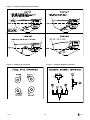
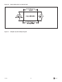
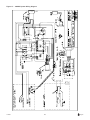
Eskimo Ice
Remote Ice Crushing System
Installation & Operation
Remote Ice Crushing System
Revised: 6-21-06
L-2448B
TABLE OF CONTENTS
Maintenance
INTRODUCTION
Seawater System .............................................................. 11
Refrigerant Gas ................................................................ 11
Compressor ...................................................................... 11
Auger Motor ...................................................................... 11
Auger Gearbox ................................................................. 11
Water Reservoir ................................................................ 11
Water Filter ....................................................................... 12
Evaporator Cleaning ........................................................ 12
Winterizing the System ..................................................... 12
Drawings and Diagrams .................................................... 3
Ice Making and Refrigeration Basics
3
Ice Maker Components ...................................................... 3
INSTALLATION
Choosing the Correct Voltage Equipment ......................... 5
Installing the Condensing Unit
11
5
Selecting the Site ............................................................... 5
Site Location Check List .................................................... 5
Mounting the Condensing Unit .......................................... 5
Installing the Auger Unit
Troubleshooting Guide
12
Limited Warranty Periods
16
Description of Figures and Diagrams
17
Site Location Check List .................................................... 5
Mounting the Auger Unit .................................................... 5
Installing the Ice Level Sensor ........................................... 6
Installing Ice Delivery Hose ............................................... 6
Installing the Refrigerant Linesets
6
Connecting the Quick Connect Fittings ............................. 6
Installing the Feed Water System
Water Quality ...................................................................... 7
Use of Saltwater as the Evaporator ................................... 7
Installing the Seawater Cooling System
7
Through-Hull Inlet Fitting .................................................... 7
Seacock .............................................................................. 7
Strainer ............................................................................... 7
Seawater Pump .................................................................. 8
Required Seawater Flow Rate ........................................... 8
Manifolds ............................................................................ 8
Overboard Discharge ......................................................... 8
Seawater Piping ................................................................. 8
Bonding .............................................................................. 8
Pump Relay ........................................................................ 8
Installing the Control Panel
8
OPERATION
Start-up Check List
Servicing the System
9
10
Refrigerant ........................................................................ 10
R134a Tools ...................................................................... 10
Constant Pressure Valve (CPV) ....................................... 10
Quick Connect Fittings (QC) ............................................ 10
Recharging the System
10
System shutdown ............................................................. 10
Evacuate Refrigerant ....................................................... 10
Charging the System ........................................................ 11
Setting the Constant Pressure Valve (CPV) .................... 11
Constant Pressure Valve (CPV) Replacement ................ 11
Copyright 2006 Dometic Environmental Corporation, All Rights Reserved - Every precaution has been taken in the preparation of this manual to insure its accuracy. However, Dometic Environmental
Corporation assumes no responsibility for errors or omissions. Neither is any liability assumed for damages resulting from the use of this product and information contained herein.
L-2448B
2
Y English
INTRODUCTION
Drawings and Diagrams
WARNING
The figures, drawings, or diagrams that are referenced
in this manual can be found directly after the warranty
section. In addition, some equipment may be shipped
with specific installation sheets or wiring diagrams that
may supercede the information located in this manual.
Dometic reserves the right to update or change any
information located herein at any time and without prior
notice.
This manual contains essential safety information
concerning the safe and proper installation, operation, and maintenance of your ice making system. It
is very important that you read and understand the
contents of this manual thoroughly before installing
or using the equipment. You should keep this manual
on your boat for future reference. Failure to follow
Dometic approved installation, start-up, operation,
and troubleshooting procedures will void the warranty. If there are any statements in this manual that
you do not understand, contact the Dometic Service
Department or your local dealer for assistance.
Ice Making and Refrigeration
Basics
Phone 804-746-1313 or 954-973-2477 (8am-5pm US
Eastern Time), Fax 804-746-7248 or 954-979-4414,
or email [email protected].
To produce crushed ice, heat must be moved from the
ice making water source to the seawater condensing
medium. The condensing unit contains both the compressor and condenser coil. The compressor adds
pressure to the refrigerant gas, which causes an
increase in temperature. The condenser coil removes
heat and condenses the refrigerant gas into liquid. The
liquid is pumped to the expansion device which lowers
the pressure and allows the refrigerant to expand in the
evaporator. When the refrigerant expands in the evaporator, it actually boils from a liquid to a gas. This
change of state allows for a large energy exchange.
After the refrigerant is fully boiled off into a gaseous
state, it flows back to the compressor again.
NOTICE
Your ice making system uses the refrigerant R134a.
Federal law forbids the intentional release of refrigerant gas to the environment. You should make certain
that any field service is performed by a specialist
with the proper equipment to prevent loss of refrigerant during servicing.
DANGER
The equipment referenced in this manual operates
on 115 or 230 volts AC. Such voltages can be lethal,
therefore, proper care must be taking during installation, operation, and servicing to prevent injury or
loss of life.
The evaporator in the ice maker allows cold refrigerant
gas to remove heat from the water. As the water
freezes onto the wall of the evaporator shell, it is
scraped off by the auger, and pushed to the box.
Ice Maker Components
DANGER
The system consists of two main components: the
condensing unit and the auger unit. They are connected by copper linesets or flexible lines. Other parts
include the control panel, seawater system, and ice
level sensor.
The equipment referenced in this manual operates
with compressed refrigerant at high pressures.
Proper care must be taken during installation,
operation, and servicing to prevent injury or loss of
life due to improper procedures.
Condensing Unit (Figure 1)
All units have R134a compressors, water-cooled
condensers, a receiver/filter/drier, an accumulator, and
a sight glass/moisture indicator. The condensing unit
also has the logic control/electrical component box
(control box) attached. The control box is attached to
the condensing unit by an eight foot cable. It has plugand-play electrical connections to the auger unit and
control panel. The control box may be remotely
mounted, but must be mounted in the same orientation
as when it was shipped. The unit comes with quick
connect refrigerant fittings and is pre-charged with
refrigerant from the factory.
DANGER
This equipment is not ignition protected per CFR
183.410 and may not be installed in areas that may
be exposed to flammable gases.
L-2448B Introduction
3
Y English
Auger Unit (Figure 2)
Freshwater Supply
The auger unit contains the evaporator barrel, auger
rotor, gearbox, motor, water reservoir, and expansion
device. The unit comes with quick connect refrigerant
fittings and is pre-charged with refrigerant from the
factory. The unit has plug-and-play electrical connections to the control box and the ice level sensor.
Freshwater supply for ice making should be provided
via the ¼" male flare fitting on the auger unit. Provide
water with pressure of at least 15 PSI. An in-line water
filter is required to help prevent clogging of the needle
valve in the water reservoir.
Refrigerant Charge
Control Panel (Figure 3)
The condensing unit, the auger unit, and the linesets
are all pre-charged with the correct amount of R134a
refrigerant. No charge adjustment should be necessary
upon installation.
The control panel contains the system function switch
as well as system indicator lights. It is a user interface
that enables a visual indicator of system activity, such
as whether the system is running or has a fault.
Sight Glass/Moisture Indicator (Figure 1)
Linesets
A sight glass is provided on the condensing unit to
provide quick access to a couple of pieces of system
information. The sight glass will provide visual identification of refrigerant charge status (empty or full.) The
sight glass also houses a moisture indicating element
which can help in troubleshooting.
Linesets are generally made of copper tubing which is
connected to the auger at one end and the condensing
unit at the other. The liquid line is ¼" copper tubing,
while the suction line is ½" copper tubing. The suction
line comes pre-insulated to prevent frost. Flexible
sections are available where one part moves in relation
to another, such a lifting deck.
Quick Connect Fittings (Figure 1)
The quick connect (QC) fittings allow for all parts of
the unit to be factory evacuated and precharged with
refrigerant. They allow for easy and quick installation in
the field. They are polarized so they can’t be hooked
up incorrectly. They can be reused over time and again
if the unit is ever relocated.
System Controls
The ice maker system is controlled by logic that is
programmed into the SmartRelay. The SmartRelay
controls all operations of the system, and gives visual
indications of activity to the user via the control panel.
The logic system takes into account low refrigerant
pressure, high refrigerant pressure, low feedwater for
ice making, blocked ice delivery system, and auger
motor start error. The control box contains a System
Reset switch for use when the control locks out due to
a sustained fault.
Constant Pressure Valve (Figure 4)
The constant pressure valve is used as the expansion
valve of the refrigerant system. It allows high pressure
liquid to become low pressure liquid and start the
refrigeration process. The constant pressure valve is
very simple and reliable, and provides for a constant
system pressure over a wide range of ambient and
seawater temperatures. The valve pressure is set at
the factory, and generally needs no field adjustment.
The recommended pressure is 9-10 PSI.
Ice Box
The ice box where the ice is to be dumped should be
insulated, if possible, with at least 2" of insulation to
help keep the ice as long as possible. It is also helpful
to install a drain at the opposite end of the box from
the ice input.
Misadjustment of the valve can cause reduced ice
production, damage to components, and voiding of the
warranty.
Seawater System (Figure 1)
The cupro-nickel coaxial tube design allows for efficient exchange of heat between the seawater and the
hot refrigerant. The condensing unit may be hooked up
to either its own single-station pump, or to a larger,
multi-station pump via a pump relay box. The seawater
system should consist of a through-hull fitting,
seacock, strainer, seawater pump, seawater hose, and
overboard discharge.
L-2448B Introduction
4
Y English
INSTALLATION
This section covers installation procedures for your ice
making system. Please read the manual completely
before attempting to install any equipment.
Use screws or bolts through the holes in the four
corners of the pan to secure the unit. You may remove
the pan and turn to get the proper orientation of the
drain stub.
Choosing the Correct Voltage
Equipment
Do not remove any covers, caps, or fittings that may
expose any wiring or refrigerant until you are ready for
that step of the installation.
The voltage rating of a unit is a nominal rating. The
voltage in a given location may be higher or lower by
as much as 10% and the system will still operate
correctly. For example, at 60 Hz, you will sometimes
see 110 VAC to 120 VAC, or 208 VAC to 240 VAC. In
a 50 Hz environment, common voltages range from
220 VAC to 240 VAC.
If you decide to remotely mount the control box, be
sure to mount in the same orientation in which the
unit was shipped. Failure to do so could cause
system failure.
When choosing your system, the voltage and frequency must be known. While this 60 Hz equipment
can be run at 50Hz, it will experience a 17% drop in
performance. When using this equipment on 50 Hz, the
voltage must be the lower of the two voltages given
(100 or 200) on the data plate due to buildup of heat in
the motor.
Installing the Auger Unit
The auger is designed to be installed close to the ice
box. This minimizes the amount of tubing between the
box and auger, and minimizes the time required for ice
to start entering the box. It also helps to reduce the
amount of melting taking place in the hose and reduce
the chance for ice clogging. The auger unit has an
elbow on the top, right-hand side which is where the
ice exits the auger itself. The elbow can rotate 360o to
accommodate the location of the hose to the ice box.
It is important that the elbow is oriented in an upward
direction to allow water to re-enter the auger barrel
instead of running to the ice box.
Installing the Condensing Unit
Selecting the Site
Dometic ice making units are designed to be installed
in any convenient location. The unit is normally located
in the engine room or other machinery space, but can
be located in living areas if necessary. The condensing
unit will produce some condensation, so the drip pan is
necessary. The space around the unit may be insulated
to reduce noise if necessary. The unit is water cooled,
and does not need ventilation.
Site Location Check List
• Choose a location as close to the ice box as
possible
• Orient the unit so that refrigerant, water, and
electrical connections are accessible
• Orient the unit so that the front and/or top cover
may be removed for service and maintenance
Site Location Check List
• Adequate space for access to refrigerant, seawater, and electrical connections
• Choose a substantial vertical surface, or a flat,
horizontal surface
• Accessible for service and maintenance
• Do not place in an area of direct salt spray
• Away from direct spray from engine air intakes or
water washdown
Mounting the Auger Unit
• Flat, horizontal surface
Orient the unit so that the refrigerant, water, and
electrical connections are accessible. Plan for enough
space in front of and on top of the unit for panel
removal. Securely fasten to a sturdy vertical wall using
the keyhole slots in the rear of the unit, or secure to a
flat, horizontal surface using the tabs provided on the
bottom of the unit.
• Maximum refrigerant tubing run is 50 feet (15m)
Mounting the Condensing Unit
Orient the unit so the refrigerant, seawater, and electrical connections are accessible.
Do not remove any caps, covers, or fittings until you
are ready for that step of the installation.
L-2448B Installation
5
Y English
Installing the Ice Level Sensor
Connecting the Quick Connect
Fittings
Use Figure 5 to determine placement for the Ice Level
Sensor. The sensor must be located below the ice
delivery hole and to the side, per Figure 5. Drill 23/32"
hole for sensor. Use two lock nuts provided to secure
sensor into hole. Use marine grade sealant around the
hole if desired. Remember that the unit may have to
be removed at some time. Route the cable to the
auger unit, and plug into the matching plug.
The linesets, auger and condensing unit all have quick
connects (QC). QC fittings allow for connection and
disconnection of the system with no loss of refrigerant.
Route the lines directly to each unit, and approach the
QC in a straight line. Do not try to screw fittings
together which are not mated correctly, as doing so will
destroy the fittings. Connect the fittings together in the
following method:
Installing Ice Delivery Hose
• Lubricate the male fitting face and thread lightly
with refrigeration grade oil.
Figure 5 and 6 shows the proper ice delivery hose
connection. The first step is to install the proper
through-hull in the ice box (Figure 5). This through-hull
must be large enough for the 1¼" ice hose to fit inside
the fitting (use supplied part). It should be installed in
such a manner as to provide (Figure 6):
• Hand thread the nut of the female QC onto the
male threaded QC by rotating the union nut
clockwise.
• Tighten the female thread connection with a
wrench while holding the opposite coupling with a
wrench. Exception: The male QC is held by a
metal bracket at each unit, and does not need a
wrench on it.
1) A continuous uphill route of travel from the auger
unit (BEST)
2) A continuous route of travel, with only one high spot
(GOOD)
• Tighten each assembly to 35 ft. lbs.
3) A route of travel which includes one low spot and
two high spots (ACCEPTABLE)
• If you don’t have a torque wrench, then tighten
each assembly until the fittings “bottom out.” Then
use a marker to make a line on each coupling half
hex. Turn with wrenches an additional 1/6 to ¼ turn
to completely seal the assembly.
The best routing provides for a level, but slightly
upward rising hose from the auger toward the box, with
very few bends. No bend should be tighter than a
radius of 12". Insulate the full length of hose with
1 5/ 8" ID, ¾" thick wall insul-tube, minimum. Provide a
¼" hole for an air vent where instructed as in Figure 6.
Do not block with insulation. If there are any dips in
the hose, we suggest that you drill a ¼" hole in the
hose for a water relief. While the water will not prevent
ice flow, it could freeze in low ambient conditions,
preventing ice delivery. Do not block the hole with
insulation. Secure at each end with double hose
clamps, so that the line will not get pulled out. In
addition, PVC glue may also be used at the thru-hull
end. Strap hose to bulkhead securely, keeping in mind
that the hose will be much heavier once filled with ice.
Be careful not to kink or crush hose, because any
obstructions will prevent free flow of ice.
IMPORTANT
If fittings are cross-threaded together by not using
the steps above, the fittings will be destroyed and
the warranty voided.
Installing the Feed Water System
The feed water for the auger unit should be fresh water
supplied by potable water system of the boat. Use of
saltwater is not recommended because of the damage
it causes to the components of the auger and evaporator barrel. Feed water should be supplied with pressure
of at least 15psi. The water system must be able to
supply at least 4 gallons per hour when the ice maker
is operating. Use of an in-line filter just prior to the
auger unit is required to remove sediment which may
cause occlusion of the needle valve in the water
reservoir, and to reduce scale buildup which will inhibit
system performance, and may cause damage to the
auger components. We suggest a filter that will remove
dirt, rust, odor, and scale, such as Dometic Part
#3150707. Dometic recommends that a shut-off valve
be installed in the feedwater line, between the source
and the filter, to help facilitate filter removal. Run
copper tubing or equal from the water source to the
auger unit, and connect with the supplied connection
Installing the Refrigerant Linesets
The refrigerant lines may run uphill, downhill, or sloping
as necessary. They can have bends as necessary, but
avoid sharp bends which could result in kinking of the
tubing. Once connections are made, the suction line
should be fully insulated from unit to unit.
L-2448B Installation
6
Y English
on the unit. Ensure that there are no leaks in the field
installed portion of the system. The water reservoir has
a float switch to ensure that the unit does not operate
without water supply.
without any dips of loops, and with only one high point
in the system. This is called self-draining because all
the water will drain out of the piping if the boat were
taken out of the water.
Whenever air gets into the system, which can happen
in heavy seas or a sharp turn, it can become trapped
in the pump. Because centrifugal pumps cannot pump
air, water flow is lost.
Water Quality
No water which comes from municipalities is ‘pure’
water. Water from the water maker on board a vessel
will come as close as you will probably see. The
problem is that water contains suspended and dissolved solids. Pure water freezes first, leaving the
solids to increase in concentration in the unfrozen
water. Solids also bond to the evaporator wall during
freezing, forming scale. Eventually, built up scale will
shorten machine life. A filter should always be used,
preferably one approved by Dometic for use with ice
makers. The filter should be replaced at least twice
yearly, or more often if the machine is used often.
While filters will help clean the water, a yearly cleaning
of the evaporator barrel is required, see the Maintenance section, under Evaporator Cleaning.
A self-draining system will allow air in the piping to
rise naturally through the pump and then be expelled.
It will also make winterizing the system much easier.
Figure 7 shows a properly plumbed system and some
common mistakes.
Through-Hull Inlet Fitting
A separate through-hull fitting must be installed for
each seawater pump. Do not attempt to draw water
from an engine, generator, or other through-hull fitting.
A scoop-type through hull should be installed facing
forward, as far below the water line and as close to the
keel as possible.
Use of Saltwater as the Evaporator
Saltwater use in the evaporator to make ice is not
approved by Dometic, even though the machine can
freezer salt water. Salt water is very corrosive in itself,
plus it contains many more dissolved and suspended
solids than freshwater. If you wish to have brine
solution for your catch, we suggest sprinkling some
salt over the ice in the catch box. USE OF SALTWATER IN ANY DOMETIC ICE MAKER WILL VOID THE
WARRANTY!
Drill a properly sized hole for the through-hull fitting.
Bed the scoop with marine sealant designed for
underwater use, and tighten the nut onto the throughhull to secure it.
Seacock
A full-flow seacock should be installed directly onto the
through-hull fitting. Use Teflon tape or equivalent to
seal the threads. The seacock must be accessible and
easy to close in case of emergency, of to clean the
strainer.
Installing the Seawater Cooling
System
Strainer
A seawater strainer must be installed between the
seacock and the pump, and should be situated to
provide easy access for cleaning. The strainer must be
located vertically above the seacock and below the
pump so any air that gets into the strainer can get out.
The following installation instructions apply to ice
maker units as well as general air conditioning units.
Importance of a Self-Draining System
A poorly plumbed seawater system is one of the most
common installation problems on marine refrigeration
and air conditioning. When water flow is lost, not only
with the ice maker cease to produce ice, but the pump
could be damaged from running with no water flow.
Make sure the water flow through the strainer is in the
correct direction. Some strainers have an arrow that
shows correct flow direction.
Mount the strainer to a bulkhead so it is properly
supported before connecting hoses. Use Teflon tape or
equivalent on pipe threads.
When using a centrifugal seawater pump, it is imperative that the seawater piping be routed continually
uphill from the through-hull to the condenser, then
smoothly up or down to the overboard discharge,
L-2448B Installation
7
Y English
Seawater Pump
• Use the correct size hose, fittings, and components. See Figure 9 for proper sizing. Note that the
pump inlet piping (including through-hull and
strainer) may need to be larger than the outlet pipe
size. Do not use pump connections to determine
hose size.
Centrifugal pumps are not self-priming, and must be
mounted so that they are below the heeled waterline in
any given operating condition. The pump should be
accessible for future service.
Mount the pump so that the outlet is directed upward.
The head on some pumps can be rotated to allow
mounting on a vertical bulkhead, see Figure 8. Selfpriming pumps are available if the pump cannot be
mounted below the waterline.
• The “pump inlet” recommended pipe size includes
all fittings and hose up to the pump connection
(through-hull, seacock, strainer, hose, manifold).
The “pump discharge” recommended pipe size
includes all fittings and hose from the pump
discharge up to the overboard discharge.
Required Seawater Flow Rate
The Dometic ice maker requires 2.5 GPM or 150 GPH
of seawater flow for rated performance.
Bonding
Bond all metallic parts (through-hull, valves, strainer,
manifolds, etc.) that are in contact with seawater to
the vessels’ bonding system in accordance with ABYC
standards. Items should only be bonded or grounded
once. If an item is in contact with an electrically
grounded part (pump, seawater condenser) then it
should not be bonded again.
Manifolds
If a pump is serving multiple units, then a seawater
manifold will be needed to supply water to all units.
This can be as simple as a tee for two units, or a
custom manifold for seven to eight units.
It is very important to consider manifold orientation so
that all units get their required flow. See Figure 9 for
proper orientation tips.
Pump Relay
The pump relay is generally located in the engine room
or mechanical space near the seawater pump, but can
be mounted anywhere that is convenient and accessible. It must be in a dry location, away from water
spray, with some room for heat dissipation.
A manifold can also be used on the outlets of the
units when using a single overboard discharge.
Overboard Discharge
Choose your pump relay based on the number of units
that will be operating off one pump. Choose each
trigger to reflect the voltage of the unit it serves. The
polarity of the signal from the unit does not matter to
the trigger, but the voltage is very important.
The overboard discharge should be located between 1
and 2 inches (25-50 cm) above the waterline. This is to
facilitate visual confirmation of water flow, but also to
keep it close to the waterline to minimize splashing.
If the overboard is located below the waterline, then a
valve must be installed per ABYC guidelines.
Seawater Piping
Installing the Control Panel
• Only use reinforced marine grade hose or other
suitable piping (PVC, CPVC, cupronickel, or
stainless steel).
The control panel may be installed wherever desired,
however, it may not be exposed to saltwater spray. The
panel comes with a plug on the back. Use extension
cables (purchased separately) to run between the panel
and the control box. They may be extended up to 100'.
Use the cutout dimensions provided in Figure 10.
Route cable to control box on condensing unit, and
plug into the mating connector.
• Double clamp all hose connections.
• Use only plastic, bronze, or stainless steel fittings
(do not use brass).
• Avoid loops or dips in all hose runs.
• Make sure enough hose is used to allow for future
removal of components.
L-2448B Installation
8
Y English
OPERATION
This section of the manual refers to essential safe
operation for all Dometic ice makers. For any operational problems, call your dealer, or our service department at 804-746-1313.
• Watch for ice within five minutes of starting, plus
approximately one minute for each foot of hose
between the box and auger unit
NOTE: The seawater pump should cycle automatically
whenever the unit is running. Regularly check for
seawater flow by observing the overboard discharge. If
you do not observe any flow when the system is
running, check for obstructions in the seawater cooling
system.
Start-up Check List
A) Before you start the system
• Check that all refrigerant connections are tightened
per installation manual
C) Control Operation
• Check to make sure that all refrigerant lines are
secured so as not to rub against other objects
during operation
• The control system works off pre-programmed logic
to operate the condensing unit and auger unit
within the assigned parameters. The logic uses
sensors, timers, and counters to protect system
components from failure due to loss of freshwater,
loss of seawater, ice clogs, low refrigerant, or
auger motor start failures. It also controls system
operation based on ice bin level.
• Ensure that all portions of the suction line,
including connections, are insulated to prevent
ice build-up
• Confirm that electrical connections are correct and
tight.
• Make sure that the ice level sensor is mounted
securely and the cable is routed safely.
• Input and output starts at the control panel. The
panel contains the system on/off switch, system
running indicator light, pressure fault light, ice clog
failure light, and the freshwater feed failure light.
These indicators help determine system function,
and failure mode, if one occurs.
• Make sure that all units are mounted securely.
• Check seawater connections to make sure that
they have correct flow direction, and that all
connections are tight.
• System failures that result in sustained shutdown,
as indicated by one of the red failure lights on the
control panel, can be reset with the Reset switch
on the control box at the condensing unit. If the
Reset switch needs to be used, it is a good
indication of an actual problem, not just a passing
event.
• Confirm that all metallic parts are bonded correctly
• Make sure there are no loops or dips in the
seawater system
• Confirm that frequently accessed parts are accessible i.e. control box, constant pressure valve,
refrigerant ports, etc.
• Required events for sustained shutdown (in need of
Reset switch operation)
• Check ice delivery hose for insulation, air hole,
and drain hole, if required. Make sure that the hose
is securely fastened.
1) High pressure switch operation of three (3)
times within 45 minutes.
B) Starting the system
2) Low pressure switch operation of six (6) times
within 45 minutes.
• Turn on the designated circuit breaker for the unit,
and also the one for the pump if it is on a separate breaker at the boat’s electrical panel
3) Freshwater feed fault each time level the fault
occurs.
• Open the seacock on the pump intake
• Turn the switch on the ice maker unit to ‘ON’
4) Ice clog indicator switch on ice discharge
nozzle each time the fault occurs.
• When the unit starts (after the two minute delay)
watch the sightglass for flowing refrigerant
5) Auger motor start error each time the fault
occurs.
• Check the sightglass after 15 minutes to make
sure that the indicator inside shows green (no
moisture)
NOTE: If system needs to be reset more than twice
within one day, please have the system serviced.
• Confirm that water is flowing through the overboard
discharge
L-2448B Operation
9
Y English
Servicing the System
This section contains information critical to correct
servicing of this Dometic ice making system. Please
read and understand all information before beginning.
If you have any questions, please call Dometic at
(804) 746-1313.
Refrigerant
Your Dometic ice making system contains R134a
refrigerant, an environmentally friendly gas, which has
no current phase-out date. R134a is a single component refrigerant and should never be charged in the
liquid phase while the unit is running. The units
contain enough refrigerant for operation when they are
received. It should not need normal or seasonal
recharging.
R134a Tools
You should use a dedicated R-134a gage set. This
system uses the common automotive type quick
connects for the gage connections. They help ensure
L-2448B Operation
10
Y English
Charging the System
6) Evacuate the system as described in “Evacuate
Refrigerant, and recharge the system with the
correct amount of R134a.
1) Remove line from vacuum pump, and connect to a
bottle of R134a. The charge should be weighted in by
placing the bottle on a refrigerant scale.
7) Set suction pressure as described in “Setting the
CPV.”
2) Turn the bottle upside down, and purge the charge
hose at the gage set.
3) Allow refrigerant to flow in the high side until the
correct charge is reached. Disconnect refrigerant
tank.
Maintenance
The periods and procedures given for maintenance and
cleaning are guides only and should not to be construed as absolute or invariable. Cleaning especially
will vary, depending on local water conditions (hard
water, etc) and the ice volume produced.
Setting the Constant Pressure
Valve (CPV)
1) Start the system and run for 15 minutes. Observe
the low pressure gage. The CPV should be adjusted
to maintain approximately 9-10 PSI.
Seawater System
Check the seawater strainer daily. Remove any debris.
If you are in waters where jellyfish or other debris is a
real problem, you may find it necessary to add a
strainer on the outside of the thru-hull fitting. Verify that
all water connections are tight, and check for water
flow from the overboard discharge. The centrifugal
pump does not need any routine maintenance.
2) Turn valve adjustment knob clockwise (in) to raise
pressure and counterclockwise (out) to lower pressure. Only make ¼ turn adjustments at the time, and
allow three (3) minutes between adjustments for
system to equalize.
3) Make sure that the valve is dry, and replace the cap
on CPV, being careful not to disturb the setting by
gripping the cap too tightly.
Refrigerant Gas
The refrigerant included in the system is adequate for
the life of the system, and should not need routine or
seasonal charging. If the need exists for routine
charging, then look for a refrigerant leak that needs
repair.
4) Remove gage set and replace service port caps.
Constant Pressure Valve (CPV)
Replacement
Compressor
The CPV is a very simple and durable metering
device. Often small blockages can be cleared by
turning the adjustment knob completely in, then back
out. In the unlikely event that the CPV is blocked or
the diaphragm ruptured, it can be replaced as follows:
The compressor has no user serviceable parts, and is
lubricated constantly during operation.
Auger Motor
The auger motor is permanently lubricated, and needs
no regular maintenance.
1) Recover refrigerant as described in “Evacuate
Refrigerant.”
2) Remove CPV from the auger.
Auger Gearbox
3) Remove the ¼" liquid line by loosening the flare nut.
Thread sealant has been applied to the flare threads,
so some extra force may be required to loosen.
The gearbox comes pre-filled with lubricant, and should
not need regular maintenance.
4) Connect the CPV to the auger. We recommend using
a threadlocker, such as LocTite 545 or equivalent,
on the threads ONLY. Tighten as you would a flare
fitting. Do not overtighten.
Water Reservoir
Quarterly clean and flush the water reservoir. Depress
the float to ensure that a full stream of water enters
the reservoir.
5) Connect the ¼" line to the new CPV. We recommend
using a threadlocker, such as LocTite 545 or equivalent, on the threads ONLY.
L-2448B Operation
11
Y English
Water Filter
Winterizing the System
Change the filter at least twice per year, or every 1500
gallons, whichever comes first. The correct filter will
help prevent clogging of the float valve, and scale
buildup within the evaporator chamber. We suggest
Dometic Part #3150707.
Close the seacock and remove the inlet hose from the
condensing unit. Allow all water to drain from the
system. Loosen the screws on the pump head to allow
water to drain from the pump. Cutoff feedwater supply,
and drain at the auger unit. Be sure to remove water
from the water reservoir inside the auger unit. You may
also add some non-toxic antifreeze to the water
reservoir.
Evaporator Cleaning
Once per year, the evaporator should be cleaned. This
should be carried out by an authorized service agency.
The following steps should be used:
Troubleshooting Guide
1) Shut off the water supply to the ice machine
Before calling for service, review this list. It may save
time and expense. This list contains potentially common occurrences that are not a result of defective
workmanship or materials. If you still need service
after trying these procedures, call you local dealer, or
the Dometic service department at (804)746-1313.
2) Disconnect clear tubing from bottom evaporator, and
drain all water from the evaporator. Reconnect the
tubing.
3) Prepare cleaning solution, mix 8 ounces of Scotsman Ice Machine Cleaner, or equivalent, with two
quarts of hot water. If other solution is used, follow
instructions on bottle.
Problem: Unit does not operate at all
4) Remove the cover to the water reservoir.
Potential Solution:
5) Slowly pour the cleaning solution into the reservoir.
1) Check for tripped breaker or blown fuses
6) Turn the machine to the ON position.
2) Significantly low voltage to unit
3) Misconnected or loose plugs or wiring
7) Continue pouring cleaning solution into the reservoir,
maintaining the level just below the overflow, while
the machine makes ice.
4) System switch in the ‘Off’ position
5) Ice level is high enough. Move ice around box.
8) Continue ice making until all of the solution is used
up, and the reservoir is empty.
Problem: Pressure fault light on.
9) Turn the machine to the OFF position.
Potential Solution:
10) Wash and rinse the water reservoir.
1) Check seawater system for clogs or faulty pump
11) Open the water supply to the ice maker
12) Turn the machine to the ON position
2) Faulty pump relay trigger at relay station (if
pump is used for more than one unit). Replace
trigger.
13) Let the machine make ice for AT LEAST 15 minutes
to flush out any remaining cleaning solution.
3) Low refrigerant charge, have a certified technician check.
14) Remove all ice from the ice bin, do not use any of
the ice produced during the cleaning cycle.
4) Improperly set Constant Pressure Valve. Set per
instructions in “Setting the CPV.”
15) Use hot water to rinse the ice bin.
Problem: Ice Clog fault light on
WARNING
Potential Solution:
Ice Machine Cleaners use strong acids. Read and
follow all instructions and warnings on the solution
container that you use.
1) Check for obstruction at the ice discharge in the
ice bin
2) Check for frozen ice delivery hose
3) Check for kinks in the ice delivery hose
4) Check for auger motor failure
L-2448B Operation
12
Y English
Problem: Feedwater fault light on
Problem: Oil in auger assembly drain pan
Potential solution:
Potential Cause/Solution
1) Check for water pressure in boat’s potable water
system
1) Water in gear reducer has raised level of the oil
so that it can run out of the weep hole on the
top of the gear housing. It may occur due to:
2) Check for a valve that has been turned off
i. Leaking water seals in the evaporator/auger
assembly, replace seals.
3) Check for a clogged feedwater filter.
4) Check for a clogged needle valve in the water
reservoir.
ii. Loose or missing drain hose on weep hole,
which might allow condensate to leak into the
weep hole.
Problem: Ice delivery volume seems
inadequate
Potential Cause/Solution:
1) High seawater temperature
2) High feedwater temperature
3) Low seawater flow, check pump and strainer
4) Drivemotor weak, replace motor
5) Corroded or stained auger due to water
condition, clean and/or replace assembly
6) Inlet water filter/strainer partially clogged,
replace filter
7) Loss of refrigerant charge, consult trained
technician
Problem: Water Leaks
Potential Cause/Solution:
1) Defective Water seal, replace seals
2) Water level in reservoir too high, adjust float
Problem: Excessive noise or chattering
from evaporator/auger assembly
Potential Cause/Solution:
1) Mineral or scale deposit on auger and evaporator
walls. Clean evaporator
2) Poor water supply, check for fouled filter or float
valve
3) Gear reducer assembly loose on mounts
4) Gearmotor end-play of worn bearing, replace
worn part
L-2448B Operation
13
Y English
Owner’s Limited Warranty
As hereinafter described, Dometic Environmental Corporation limits the duration of any implied warranty to the duration of the
underlying express warranty and also disclaims any liability for consequential or incidental damages arising from any application,
installation, use or malfunction of any warranted product.
Section I
Section II
What does the Limited Warranty cover?
What does this Limited Warranty not cover?
This Warranty Shall Not Apply to:
Products manufactured by Dometic Environmental Corporation
(Dometic) are under limited warranty to be free from defects in
workmanship or materials under normal use and service with the
obligation of Dometic under this limited warranty being limited to
replacing or repairing any component(s) which shall disclose
defects within the time limits defined in Section III and which,
upon examination by Dometic, shall appear to the satisfaction of
Dometic to be defective or not up to specifications.
This Limited Warranty is made in lieu of all other
express warranties, obligations, or liabilities on the
part of Dometic. In addition, Dometic shall not be
responsible for any incidental or consequential
damages. In those instances in which a cash refund is made,
such refund shall effect the cancellation of the contract of sale
without reservation of rights on the part of the purchaser. Such
refund shall constitute full and final satisfaction of
all claims which purchaser has or may have against
Dometic due to any actual or alleged breach of
warranty, either express or implied, including,
without limitation, any implied warranty of merchantability or fitness for a particular purpose. Some
states do not allow the exclusion or limitation of incidental or
consequential damages so the above limitation may not apply to
you. The terms and conditions of this warranty shall be governed
by the laws of the Commonwealth of Virginia.
The Dealer is not an agent for Dometic except for the purpose of
administering the above warranty to the extent herein provided, and
Dometic does not authorize the dealer or any other person to
assume for Dometic any liability in connection with such warranty,
or any liability or expense incurred in the replacement or repair of
its products other than those expressly authorized herein. Dometic
shall not be responsible for any liability or expense except as is
specifically authorized and provided in this section.
Failures resulting from improper installation or use contrary to
instructions.
2.
Failures resulting from abuse, misuse, accident, fire, or
submergence.
3.
Any part manufactured by Dometic which shall have been
altered so as to impair its original characteristics.
4.
Any parts which fail as a result of misuse, improper application
or improper installation.
5.
Items not manufactured by Dometic, i.e., items which are
purchased from another manufacturer and supplied as
received by Dometic without alteration or modification except
as any part of an Dometic-manufactured unit or component.
6.
Components or parts used by or applied by the purchaser as
an integral part of products not manufactured by Dometic.
7.
Warranty does not cover damage to components that
comprise a Custom Wrapped Box Evaporator refrigeration
system (aka: catch boxes, fish boxes, etc.) when the box is
installed in such a way that the customer can move it. These
damages may include, but are not limited to: crimped refrigerant linesets (copper tubing or flexible linesets), refrigerant
leaks, moisture ingression into the refrigeration system,
subsequent damage to condensing unit from being operated
with low refrigerant charge or moisture in the system, broken
refrigerant connections, broken thermostat sensors, and/or
broken constant pressure valves.
Installation and application of Dometic components is not warranted
by Dometic because Dometic has no control or authority over the
selection, location, application, or installation of these components.
Section III
Dometic reserves the right to improve its products through
changes in design or material without being obligated to incorporate
such changes in products of prior manufacture, and to make
changes at any time in design, materials, or part of units of any one
year's model, without obligation or liability to owners of units of the
same year's model of prior manufacture.
What is the period of coverage?
See the Limited Warranty Periods, document # L-0694, for the
period of coverage.
All Dometic components bear a data plate on which there are model
and serial numbers. The serial number is date coded. To determine
whether or not any Dometic component is in warranty, proceed as
follows:
This warranty gives you, the purchaser, specific legal rights, and
you may also have other rights which vary from state to state. You
also have implied warranty rights, including an implied warranty of
merchantability, which means that your product must be fit for the
ordinary purposes for which such goods are used. The duration
of any implied warranty rights is limited to the
duration of the express warranty as found in Section
III. Some states do not allow limitations on how long an implied
warranty lasts, so the above limitation may not apply to you.
L-2448B
1.
1.
14
Determine the manufacture date of the component from the
serial number on the data plate. If you are not familiar with the
date code, write or call the Dometic Customer Service
Department at (804)746-1313, to obtain the manufacture date.
Y English
WARNING
The hours of the Customer Service Department are 8:00 am 5:00 pm (USA, Eastern Time Zone) Monday through Friday
excluding holidays.
Dometic Environmental Corporation (Dometic) manufacturers of Cruisair,
Dometic Auxiliary A/C, Dometic Refrigerators and Freezers, Eskimo Ice,
Grunert, Marine Air, and Sentry products, makes the following safety
warnings concerning the application, installation, use and care of its products.
Although these warnings are extensive, there may be specific hazards which
may arise out of circumstances which we have not outlined herein. Use this
as a guide for developing an awareness of potential hazards of all kinds.
Such an awareness will be a key factor in assuring your SAFETY and comfort.
2. It is possible that there might exist a considerable time lag
between the date a component is manufactured and the date it
is put in service. In such instances, the date of manufacture
could indicate that the item is out of warranty. However, based
on the date the equipment is first put in service, the item may
still be covered by the Dometic warranty described in
Section I. For proof of date put in service, Dometic will
require a copy of the bill of sale of the Dometic equipment from
the installer or new boat dealer to the original owner.
ELECTRICITY - Many Dometic products operate on 115, 230 or 440 volt AC
power. Such voltages can be LETHAL; therefore, the chassis, cabinets,
bases, etc., on all components must be grounded together and connected to
the vessel's grounding system. Sparks can occur as switches, thermostats
and relays open and close in the normal operation of the equipment. Since
this is the case, ventilating blowers for the removal of hazardous fumes or
vapors should be operated at least 5 minutes before and during operation of
any Dometic product or group of Dometic products. All electrical connections
must be covered and protected so accidental contact cannot be made by
persons using the equipment, as such contact could be LETHAL.
Section IV
ELECTROLYSIS - Electrical leakage of any component can cause electrolytic
deterioration (electrolysis) of thru-hull components which could result in
leakage serious enough to sink a vessel which could result in loss of life. All
Dometic components must be kept clean and dry and checked periodically for
electrical leakage. If any electrical leakage is detected, the component should
be replaced or the fault causing the leakage corrected before the component
is put back into service.
How do you get service? Please Read the
following Warranty Procedure.
WARRANTY PROCEDURE
GAS - Dometic Air Conditioning and Refrigeration components utilize R-22
(Chlorodifluoromethane), R134a refrigerant (Tetrafluoroethane), R-407C (which
contains Diflouromethane [HFC-32], Pentafluoroethane [HFC125], and 1.1.1.2
-Tetrafluoroethane [HFC134a]), R404A (R125/R143a/R134 [44%/52%/4%]), or
R417a, which are non-toxic, non-flammable gases; however, these gases
contain no oxygen and will not support life. Refrigerant gas tends to settle in
the lowest areas of the compartment. If you experience a leak, evacuate all
personnel, and ventilate area. Do not allow open flames in the area of leaks
because refrigerant gas, when burned, decomposes into other potentially
LETHAL gases. Refrigerant components operate at high pressure and no
servicing should be attempted without gloves, long-sleeved clothing and eye
protection. Liquid refrigerant gas can cause severe frost burns to the skin
and eyes.
If the failure of a Dometic component is determined to be covered
under the Dometic warranty and the time in service is determined
to be within the warranty time limit, the owner has the following
three options:
1. Preferred option: Have a Dometic authorized Servicing Dealer
perform the work needed. The customer should call Dometic's
Service Department for a recommendation as to the closest
dealer. If the customer already knows an authorized servicing
dealer, the dealer should be contacted directly.
2.
VENTILATION - To cool or heat air, Dometic Air Conditioning and Refrigeration
components are designed to move air through a heat exchanger by a blower
or propeller fan. This design necessarily produces a suction on one side of
the air handling component and a pressure on the other side. Air handling
components must be installed so that the suction-pressure action does not:
(1) pressurize an area to the extent that structural failure occurs which could
cause harm to occupants or bystanders, or (2) cause a suction or low
pressure in an area where hydrogen gas from batteries, raw fuel vapor from
fuel tanks, carbon monoxide from operating propulsion engines, power
generators or heaters, methane gas from sewage holding tanks, or any other
dangerous gas or vapor could exist. If an air handling unit is installed in such
a manner that allows potentially lethal gases or vapors to be discharged by
the air handling unit into the living space, this could result in loss of life.
If the customer contacts Dometic's Service Department for a
Servicing Dealer and Dometic has no one in that particular
area, Dometic will authorize the use of a local service
company and Dometic will work with the local company to
assist in any way possible.
3. The customer may send his equipment back to the factory to
have the repair work done. Dometic will make every effort to
return the equipment to the customer within a three week time
period. If the claim represents a legitimate warranty problem,
Dometic will pay the freight both ways. Dometic prefers option
one and two, if at all possible.
Maximum protection against the introduction of dangerous gases or vapors
into living spaces can be obtained by providing living spaces which are
sealed from all other spaces by use of airtight bulkheads and decks, etc.,
and through the introduction of clean air into the living space. Bear in mind
that the advent of air conditioning, whether it be for cooling or for heating,
naturally leads to the practice of closing a living space tightly. Never close all
windows and doors unless auxiliary ventilating systems, which introduce
clean outside air into the living space, are used. Always leave enough window
and door openings to provide adequate ventilation in the event potentially
lethal gases or fumes should escape from any source.
The customer may contact the Dometic Service Department at
(804) 746-1313.
CONDENSATE - All cooling units produce water condensate when operating on
the cooling cycle. This water must be drained from the cooling unit overboard.
If condensate is allowed to drip on a wooden structure, rotting or decay and
structural failure may occur which could result in loss of life. If condensate is
allowed to drip on electrical components, deterioration of the electrical
components could result in hazardous conditions. When an air conditioning
system is in operation, condensate drains may be subjected to negative
pressure. Always locate condensate drains as far as possible from points
where engine waste and other dangerous gases are exhausted so no such
dangerous gases can be drawn into the condensate drains.
Warning
L-0123
L-2448B
Never sleep in a closed area on a boat when any equipment, which functions
as a result of the combustion of a volatile fuel, is in operation (such as
engines, generators, power plants, or oil-fired heaters, etc.). At any time, the
exhaust system of such devices could fail, resulting in a build-up of LETHAL
gases within the closed area.
Warning Revised: 6-5-06
Revised: 6-5-06
15
Y English
Limited Warranty Periods
Please read and keep this document with your important paperwork. Use it as a reference in the future. If you have any questions, please
contact the Dometic Environmental Corporation Service Department at (804)746-1313 for clarification.
Note: Any model or replacement part that has been installed due to a warranty failure will carry only the remainder of the original warranty.
All warranties begin when the customer takes possession of the equipment. The warranty is extended to all owners of the equipment
commencing the date the original owner takes possession of it. Proof of original purchase may be required. Fuses and MOV’s are used as
safety devices to protect Cruisair equipment against over-current conditions caused by lightning or inductive switching environments. These
are not covered under warranty. We reserve the right to change our warranty policies and procedures as well as our warranty allowances
without notice.
Cruisair Direct Expansion (DX)
and Modulating Systems
Ice Makers, Remote and Self-Contained
• New installation of an entire Self-Contained Ice Maker
• New, complete system installation using any member of the
SMX family.
1 year warranty including Parts and Labor, including water pump.
The warranty includes the pump.
• New installation of an entire Remote Ice Maker, including
condensing unit, remote display, auger unit, linesets
2 year warranty including Parts and Labor
1 year warranty including Parts and Labor, including water pump.
• New, complete system installation using an electro-mechanical
control (3-knob).
• New installation of an Remote Ice Maker Auger and Condensing
unit only, with linesets done by others i.e. not Eskimo precharged linesets
The warranty includes the pump.
1 year warranty including Parts and Labor
1 year warranty including Parts and Labor on
mechanical and electrical parts of the auger and
condensing unit only.
• New, complete model sold as a partial system retrofit to an
existing system.
Includes SMX family.
• New complete component sold as a partial system retro-fit to an
existing Eskimo system
1 year warranty including Parts and Labor
1 year warranty including Parts and Labor on new
component only.
Cruisair Tempered Water
Note: Use of saltwater as feedwater to make ice will void
warranty on the auger section of the unit.
• New, complete system installation using any member of the
SMX family.
2 year warranty including Parts and Labor
Sentry Battery Chargers
NOTE: Excludes pump which has a 1 year warranty
• New SM and FR series installation.
• New, complete model sold as a partial system retrofit to an
existing system.
2 year warranty including Parts and Labor
Includes SMX family.
• New G-series installation.
1 year warranty including Parts and Labor
1 year warranty including Parts and Labor
Refrigerators/Freezers/Fish Boxes
Replacement Parts
The below warranty periods do not apply to systems that are
installed as described in Section II, item #7, of the Owner’s Limited
Warranty, document # L-0123.
• Replacement parts and components
Example: A-509, 40401-30.
• New installation of entire system including condensing unit, line
sets, evaporator, etc.
• Replacement Compressors for other than Tempered Water
Systems - example: R3101-16T, DX equipment - installed in an
existing Cruisair system or a competitor’s system.
90 day warranty, Parts only
1 year warranty including Parts and Labor
1 year warranty including Parts and Labor
• New complete model sold as a partial system retrofit to an
existing Cruisair system.
• Replacement compressors for Tempered Water - example:
30130-36 installed in an existing Cruisair system.
1 year warranty including Parts and Labor
1 year warranty including Parts and Labor
• New installation of condensing unit only, with line sets, evaporators, etc. done by others i.e. not Cruisair pre-charged line sets
and evaporators.
• A Tempered Water compressor - example: 30130-36 installed
with competitor’s equipment.
1 year warranty including parts and labor on
mechanical and electrical parts of condensing
unit only.
90 day warranty, Parts only
Revised: 6-2-06 L-0694
L-2448B
16
Y English
DESCRIPTION OF FIGURES AND DIAGRAMS
Figure 1 – Condensing unit
Figure 2 – Auger unit
Figure 3 – Control Panel
Figure 4 – Constant Pressure Valve
Figure 5 – Photoelectric Eye Location
Figure 6 – Ice Delivery Hose Routing
Figure 7 – Seawater Piping Recommendations
Figure 8 – Pump Head Orientation
Figure 9 – Seawater Manifold Orientation
Figure 10 – Cutout Dimensions for Control Panel
Figure 11 – Complete System Hookup Diagram
Figure 12 – 120VAC System Wiring Diagram
Figure 13 – 240VAC System Wiring Diagram
Figure 14 – Condensing unit diagram
Figure 15 – Auger unit diagram
L-2448B
17
Y English
Figure 1 – Condensing unit
Figure 4 – Constant Pressure Valve
Seawater
Condenser
Sight
Glass
Quick Connects
Figure 5 – Photoelectric Eye Location
Figure 2 – Auger unit
Front View
Figure 3 – Control Panel
System
Running
Ice Delivery
Fault
Feedwater
Fault
Pressure
Fault
System
Power
L-2448B
18
Y English
Figure 6 – Ice Delivery Hose Routing
L-2448B
19
Y English
Figure 7 – Seawater Piping Recommendations
Figure 8 – Pump Head Orientation
L-2448B
Figure 9 – Seawater Manifold Orientation
20
Y English
Figure 10 – Cutout Dimensions for Control Panel
Figure 11 – Complete System Hookup Diagram
L-2448B
21
Y English
Figure 12 – 120VAC System Wiring Diagram
L-2448B
22
Y English
Figure 13 – 240VAC System Wiring Diagram
L-2448B
23
Y English
Figure 14 – Condensing unit diagram
L-2448B
24
Y English
Figure 15 – Auger unit diagram
L-2448B
25
Y English
L-2448B
26
Y English
L-2448B
27
Y English
Dometic Environmental Corporation
2000 N. Andrews Ave. Ext. • Pompano Beach, FL 33069-1497 USA • Phone: 954-973-2477 • Facsimile: 954-979-4414
P.O. Box 15299 • Richmond, VA 23227-0699 USA • Phone: 804-746-1313 • Facsimile: 804-746-7248
Website: www.EskimoIceMachine.com • Email: [email protected]
L-2448B