1
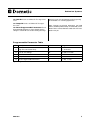
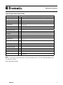
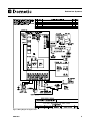
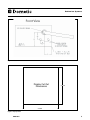
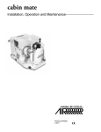
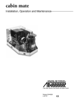
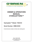
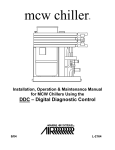
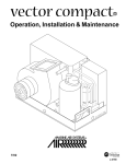
ENGLISH
Ice Flow
Water Flow
High Pressure
Low Pressure
Comp
Auger
Ice Bin
Full
Power
On/Off
Function
Dometic Eskimo Ice
Crushed Ice systems
OPERATION MANUAL
For Self-Contained & Remote Systems
Using Digital Controls (For b-16 to c-18 Software)
Dometic Corporation, Marine Division
Rev. 20100730
L–2514
COPYRIGHT © 2007, 2008 Dometic Corporation, All Rights Reserved.
No part of this publication may be reproduced, translated, stored in a retrieval system, or transmitted in any form or by any means electronic, mechanical,
photocopying, recording or otherwise without prior written consent by Dometic Corporation. Every precaution has been taken in the preparation of this manual to
insure its accuracy. However, Dometic Corporation assumes no responsibility for errors and omission. Neither is any liability assumed for damages resulting from
the use of this product and information contained herein.
Eskimo Ice Systems
DOMETIC ESKIMO ICE CONTROL OPERATION MANUAL
Contents
INTRODUCTION
4
Operation
4
Events that can interrupt normal production
4
Programmable Parameters
5
Program Parameter Description
5
Programmable Parameter Table
6
Typical Operation Cycle Table
7
Owner's Limited warranty
10
Limited Warranty Periods
12
Dealer Locator
13
ENGLISH
3
Eskimo Ice Systems
INTRODUCTION
This operation manual provides information for self-contained and remote Eskimo Ice
Systems using digital controls. Please refer to Eskimo Ice Manual L-2448A for installation of the self-contained system and L-2448B for installation of the remote system.
Please Note: The supplied main cartridge filter must be installed or the
warranty will be VOID!
Operation
Applying Power - When power is first applied,
the display will light all LED’s for 2 seconds, then go
blank for 1 second, then show software revision for 2
seconds. The unit will then go to the last state it was
in before power was disconnected. The power LED
will remain lit anytime power is applied.
On/Off - Press the On/Off button to toggle between
Off and ICE production. dLY will appear in the display
and the unit will begin a startup routine. ICE will
appear in the display when production begins.
Ice Bin Sensor - When the ice bin is full, the unit will
stop ice production and the display will show Full.
Operational LED’s - Ice Flow, Water Flow, High
Pressure, and Low Pressure are trouble lights on the
display and will light if a fault occurs and a fault code
will be displayed. Comp and Auger are status lights
and show operation of these systems. Full is also a
status light that is on whenever the ice bin is Full.
Operational Information - Compressor current,
Auger current, and AC voltage can be viewed while
the unit is in operation. Simultaneously press and
release the On/Off and Function buttons. CA will
appear in the display and after 5 seconds, a value
indicating the compressor current in amps will show.
Press Function to change to AA and auger current in
amps will display. Press Function again and AC line
voltage will display. Press the On/Off button to exit
from this feature.
Fault History - History of faults that occur can be
viewed from the off setting. Press and hold the On/Off
button for 3 seconds. This will enter the fault history
log. The display will indicate H 1. Press the function
button to scroll through the events recorded in the log.
The unit will record up to 16 events. While viewing, the
display will alternate between the fault mnemonic and
the event number. To exit the history mode, press the
On/Off button. The unit will also exit the history log in
ENGLISH
30 seconds if no key is pressed. Faults are recorded
in the order they occur, most recent to oldest.
Events that can interrupt normal
production
If trouble occurs during operation the fault codes
defined below will be displayed. Trouble LED’s will
be lit for High Pressure, Low Pressure, Water Flow,
and Ice Flow. The unit will restart once the fault is
cleared or repaired. Excessive faults will result in
the code flashing on the display called a lockout. A
lockout may be cleared by pressing the On/Off button
to turn the unit off then on again, by pressing the reset
switch or pressing the function button.
LPF - Low Pressure Freon. If the Low Pressure Freon Switch is open during production for 60
seconds, the display will show LPF fault and the Low
Pressure LED will light. The compressor delay is then
activated for restart. The auger will continue to run
for the duration of the auger delay. At the end of the
compressor delay the unit will show dLY beginning the
restart routine. This switch is checked at the start of
a cycle and during operation. The compressor delay
begins from the moment the switch is opened. Three
faults in a 30 minute period will result in a lockout.
LPF can be caused by, Low refrigerant levels, Seawater below 50°, or faulty low pressure switch.
HPF – High Pressure Freon. If the High Pressure
Freon Switch is open during production for ~500ms,
the display will show HPF fault and the High Pressure
LED will light. The compressor delay is then activated
for restart. The auger will continue to run for the duration of the auger delay. At the end of the compressor delay the unit will show dLY beginning the restart
routine. The compressor delay begins from the
moment the switch is opened. The maximum number
of faults that can occur in 30 minutes is set for three
by default. HPF can be caused by lack of seawater
flow due to a dirty strainer, pump being airlocked or
seawater lines in need of maintenance.
4
Eskimo Ice Systems
H20 – Potable water switch. If the potable water
switch is open during production for 15 seconds, the
display will show H20 fault and the Water Flow LED
will light. The auger will continue to run for the duration of the auger delay. Ice production will stop and
the switch must be closed for operation to restart.
H20 Fault can be caused by lack of fresh water flow,
clogged main filter or a clogged Y Strainer.
SPt – Auger spout blockage. If the spout switch
opens for ~100ms during production Spt fault will
show on the display and the Ice Flow LED will light.
All operation will stop including the auger. The blockage must be removed for production to restart. The
maximum number of faults that can occur in a 30
minute period is set for three by default. Spt fault
can be caused by improper delivery hose run, make
sure the hose run goes up hill from the auger spout
and does not have any 90°, sharp turns, or menders
installed, make sure that the surface where the delivery hose meets the thruhull is smooth to avoid trapping ice.
Note: If HPF, H20 or Spt appear steady on the display
(not flashing) on initial start up this may be due
to an open pressure switch, defective water level
switch, empty reservoir, open spout switch or clog.
This can also occur from an open switch or wiring
to the switch.
OCC – Overload Current Compressor. If the
compressor current exceeds 25 amps for 230VAC or
50A for 115VAC equipment for ~200ms the unit will
stop the compressor. Auger operation will continue
for the duration of the auger delay then stop and lock
out.
OCA – Over Current Auger. If the auger current
exceeds 2.5 amps for 230VAC or 5A for 115VAC
equipment for ~200ms the unit will stop all operation
and lock out.
LAC – Low AC line voltage. If the line voltage to
unit is less than value selected in the programmable
parameter for 5 minutes continuously the unit will stop
operation. The compressor delay is started and the
unit will restart at the end of the delay if the voltage is
greater than the value selected in the programmable
parameter. Parameter default is set to off.
UCC – Under Current Compressor. If the
compressor current is less than the default value of 5
amps (115 volt) or 2 amps (230 volt) for ~200 ms the
unit will stop operation and lock out. The auger will
continue to run for the duration of the auger delay.
ENGLISH
UCC fault can be caused by over voltage or open
wire.
UCA – Under Current Auger. If the auger current
is less than the default value .5 amps for ~200 ms
the unit will stop all operation and lock out. UCA fault
can be caused by over voltage, open wire or open
thermal overload.
If you experience erratic behavior such as reoccurring nuisance faults or erratic display behavior reboot
the system by shutting off at breaker for 30 seconds
and powering back up. This should clear any glitches
caused by power surge, spikes or brown outs.
Programmable Parameters For
Software as of 01-01-2008
To confirm software revision, first turn off power to
unit. When power is first applied the display will light
all LEDs for 2 seconds. Next, the display will go blank
for 1 second, lastly, the display will show the software
revision for 2 seconds.
There are numerous programmable parameters with
their factory defaults described in this section. The
table on the next page defines the parameter codes
along with the permitted values and default settings.
Parameters P1 / t-1-t5 are user settable parameters.
Enter the (P) program mode by pressing and holding
both the On/Off and Function buttons for 5 seconds
in the Off mode. To enter the (T) programming mode
first enter the (P) programming mode then push and
hold the RESET SWITCH on the control box for 15
seconds until the t-1 appears. Use the On/Off button
to advance through parameters. The Function button
is used to select the parameter value desired. Exit the
program mode either by pressing and releasing both
buttons or by waiting 60 seconds.
See Figure 1, Programmable Parameters Table.
Program Parameter Description
P-1: t-1: High Pressure Restart Delay - This
delay is used to set the start compressor restart delay after
a high Freon pressure fault is cleared. The default setting
is 0 and can be set from 0-30 minutes. Default "0" for off
is mainly used for sport fishing where backing down can
cause an airlock. Only use for continuous nuisance trips.
t-2: Low AC Line Voltage - This option can be set
to detect low AC line voltage. Low AC line voltage condition
must exist for 5 minutes for a shtudown to occur. Default
setting is off and can be set from 75 to 100 or 175 to 200.
5
Eskimo Ice Systems
t-3: CAN ID: Used to set CAN bus ID. The range is from
1-254.
t-4: Group ID: Used to set CAN bus ID. The range is
from 1-254.
t-5: Reset Programmable Parameters: Resets
all programmable parameters to factory defaults. Set this
setting to 1 and unit will reset all values. Setting will change
back to 0 on exit of the programming mode or by pressing
the On/Off button to scroll through parameters.
Note: Changes to technical parameters not listed
above should be performed by an authorized service
dealer. Please contact Dometic at 800-542-2477 for a
dealer near you.
Programmable Parameter Table
No
Description
Default
Range
P-1
t-1
High Pressure Restart Delay
0
0 - 30 minutes
t-2
Low AC Line Voltage
off
75-100 or 175-200
t-3
CAN ID
n/a
1-254
t-4
Group ID
5
1-254
t-5
Reset Programmable Parameters
0
0 = No, 1 = Yes
Figure 1. Programmable Parameter Table
ENGLISH
6
Eskimo Ice Systems
Typical Operation Cycle Table
ACTION
Delay before Next Step (in seconds) and/or description of action
Initial Start Up Via Breaker
60
Pump ON
30
Auger ON
15
Assumed display is in ON position. If not, turn unit on via display.
Compressor ON
Will continue until sensor reads bin full for 30 sec., fault trip or unit manually
shut down.
Ice Production
BIN FULL
30
Auger Clears
Machine Shuts Down
Ice removed from bin
Sensor reads bin not full, calls for ice production.
Pump ON
30
Auger ON
15
Compressor ON
Will continue until sensor reads bin full for 30 sec., fault trip or unit manually
shut down.
Ice Production
FAULT Trip - HPF, LPF,
etc.
30
Clearing Auger
Machine Shuts Down
60
Fault Trip Corrected
Pump ON
30
Auger ON
15
Compressor ON
Ice Production
Will continue until sensor reads bin full for 30 sec., fault trip or unit manually
shut down.
Note:
Above is an example of a typical operation cycle based on default values, cycle will change depending on end
user parameter changes.
Figure 2. Typical Operation Cycle
ENGLISH
7
Eskimo Ice Systems
Figure 3. Wiring Diagram for digital control
ENGLISH
8
Eskimo Ice Systems
Figure 4. Location of Ice Bin Sensor
Display Cut Out
Dimensions
3.1875
3.1875
Figure 5. Display Cutout
ENGLISH
9
Eskimo Ice Systems
Owner's Limited warranty
As hereinafter described, Dometic Corporation limits the duration of any implied warranty to the duration of the
underlying express warranty and also disclaims any liability for consequential or incidental damages arising from
any application, installation, use or malfunction of any warranted product.
Section I
Section II
What does the Limited Warranty cover?
What does this Limited Warranty not cover?
Products manufactured by Dometic Corporation (Dometic) are
under limited warranty to be free from defects in workmanship
or materials under normal use and service with the obligation of
Dometic under this limited warranty being limited to replacing or
repairing any component(s) which shall disclose defects within
the time limits defined in Section III and which, upon examination
by Dometic, shall appear to the satisfaction of Dometic to be
defective or not up to specifications.
This Warranty Shall Not Apply to:
This Limited Warranty is made in lieu of all other express
warranties, obligations, or liabilities on the part of Dometic. In
addition, Dometic shall not be responsible for any incidental
or consequential damages. In those instances in which a cash
refund is made, such refund shall effect the cancellation of the
contract of sale without reservation of rights on the part of the
purchaser. Such refund shall constitute full and final satisfaction
of all claims which purchaser has or may have against Dometic
due to any actual or alleged breach of warranty, either express
or implied, including, without limitation, any implied warranty of
merchantability or fitness for a particular purpose. Some states do
not allow the exclusion or limitation of incidental or consequential
damages so the above limitation may not apply to you. The terms
and conditions of this warranty shall be governed by the laws
of the state of Florida.
The Dealer is not an agent for Dometic except for the purpose of
administering the above warranty to the extent herein provided,
and Dometic does not authorize the dealer or any other person
to assume for Dometic any liability in connection with such
warranty, or any liability or expense incurred in the replacement
or repair of its products other than those expressly authorized
herein. Dometic shall not be responsible for any liability or
expense except as is specifically authorized and provided in
this section.
Dometic reserves the right to improve its products through
changes in design or material without being obligated to incorporate such changes in products of prior manufacture, and to
make changes at any time in design, materials, or part of units
of any one year’s model, without obligation or liability to owners
of units of the same year’s model of prior manufacture.
This warranty gives you, the purchaser, specific legal rights, and
you may also have other rights which vary from state to state. You
also have implied warranty rights, including an implied warranty
of merchantability, which means that your product must be fit
for the ordinary purposes for which such goods are used. The
duration of any implied warranty rights is limited to the duration
of the express warranty as found in Section III. Some states do
not allow limitations on how long an implied warranty lasts, so
the above limitation may not apply to you.
ENGLISH
1.
Failures resulting from improper installation or use contrary
to instructions.
2.
Failures resulting from abuse, misuse, accident, fire, or
submergence.
3.
Any part manufactured by Dometic which shall have been
altered so as to impair its original characteristics.
4.
Any parts which fail as a result of misuse, improper application or improper installation.
5.
Items not manufactured by Dometic, i.e., items which are
purchased from another manufacturer and supplied as
received by Dometic without alteration or modification
except as any part of an Dometic-manufactured unit or
component.
6.
Components or parts used by or applied by the purchaser as
an integral part of products not manufactured by Dometic.
7.
Warranty does not cover damage to components that
comprise a Custom Wrapped Box Evaporator refrigeration
system (aka: catch boxes, fish boxes, etc.) when the box is
installed in such a way that the customer can move it. These
damages may include, but are not limited to: crimped refrigerant linesets (copper tubing or flexible linesets), refrigerant
leaks, moisture ingression into the refrigeration system,
subsequent damage to condensing unit from being operated
with low refrigerant charge or moisture in the system, broken
refrigerant connections, broken thermostat sensors, and/or
broken constant pressure valves.
Installation and application of Dometic components is not
warranted by Dometic because Dometic has no control or
authority over the selection, location, application, or installation
of these components.
Section III
What is the period of coverage?
See the Limited Warranty Periods, document # L-0694, for the
period of coverage.
All Dometic components bear a data plate on which there are
model and serial numbers. The serial number is date coded. To
determine whether or not any Dometic component is in warranty,
proceed as follows:
1.
Determine the manufacture date of the component from the
serial number on the data plate. If you are not familiar with
the date code, write or call the Dometic Customer Service
10
Eskimo Ice Systems
Department at (954) 973-2477, to obtain the manufacture
date. The hours of the Customer Service Department are
8:00 am - 5:00 pm (USA, Eastern Time Zone) Monday
through Friday excluding holidays.
2.
It is possible that there might exist a considerable time lag
between the date a component is manufactured and the date
it is put in service. In such instances, the date of manufacture
could indicate that the item is out of warranty. However,
based on the date the equipment is first put in service, the
item may still be covered by the Dometic warranty described
in Section I. For proof of date put in service, Dometic will
require a copy of the bill of sale of the Dometic equipment
from the installer or new boat dealer to the original owner.
Section IV
How do you get service? Please Read the following
Warranty Procedure.
WARRANTY PROCEDURE
If the failure of a Dometic component is determined to be covered
under the Dometic warranty and the time in service is determined
to be within the warranty time limit, the owner has the following
three options:
1.
Preferred option: Have a Dometic authorized Servicing
Dealer perform the work needed. The customer should
call Dometic’s Service Department for a recommendation
as to the closest dealer. If the customer already knows an
authorized servicing dealer, the dealer should be contacted
directly.
2.
If the customer contacts Dometic’s Service Department for
a Servicing Dealer and Dometic has no one in that particular area, Dometic will authorize the use of a local service
company and Dometic will work with the local company to
assist in any way possible.
3.
The customer may send his equipment back to the factory
to have the repair work done. Dometic will make every effort
to return the equipment to the customer within a three week
time period. If the claim represents a legitimate warranty
problem, Dometic will pay the freight both ways. Dometic
prefers option one and two, if at all possible.
The customer may contact the Dometic Service Department at
(954) 973-2477.
WARNING
Dometic Corporation (Dometic) manufacturers of Cruisair, Dometic Auxiliary A/C,
Dometic Refrigerators and Freezers, Eskimo Ice, Grunert, Marine Air, and Sentry
products, makes the following safety warnings concerning the application, installation, use and care of its products. Although these warnings are extensive, there
may be specific hazards which may arise out of circumstances which we have not
outlined herein. Use this as a guide for developing an awareness of potential hazards
of all kinds. Such an awareness will be a key factor in assuring your SAFETY and
comfort.
ELECTRICITY - Many Dometic products operate on 115, 230 or 440 volt AC power.
Such voltages can be LETHAL; therefore, the chassis, cabinets, bases, etc., on all
components must be grounded together and connected to the vessel’s grounding
system. Sparks can occur as switches, thermostats and relays open and close in the
normal operation of the equipment. Since this is the case, ventilating blowers for the
removal of hazardous fumes or vapors should be operated at least 5 minutes before
and during operation of any Dometic product or group of Dometic products. All electrical connections must be covered and protected so accidental contact cannot be
made by persons using the equipment, as such contact could be LETHAL.
ELECTROLYSIS - Electrical leakage of any component can cause electrolytic deterioration (electrolysis) of thru-hull components which could result in leakage serious
enough to sink a vessel which could result in loss of life. All Dometic components
must be kept clean and dry and checked periodically for electrical leakage. If any
electrical leakage is detected, the component should be replaced or the fault causing
the leakage corrected before the component is put back into service.
GAS - Dometic Air Conditioning and Refrigeration components utilize R-22 (Chlorodifluoromethane), R134a refrigerant (Tetrafluoroethane), R-407C (which contains
Diflouromethane [HFC-32], Pentafluoroethane [HFC125], and 1.1.1.2 -Tetrafluoroethane [HFC134a]), R404A (R125/R143a/R134 [44%/52%/4%]), or R417a, which
are non-toxic, non-flammable gases; however, these gases contain no oxygen
and will not support life. Refrigerant gas tends to settle in the lowest areas of the
compartment. If you experience a leak, evacuate all personnel, and ventilate area.
Do not allow open flames in the area of leaks because refrigerant gas, when burned,
decomposes into other potentially LETHAL gases. Refrigerant components operate
at high pressure and no servicing should be attempted without gloves, long-sleeved
clothing and eye protection. Liquid refrigerant gas can cause severe frost burns to
the skin and eyes.
VENTILATION - To cool or heat air, Dometic Air Conditioning and Refrigeration
components are designed to move air through a heat exchanger by a blower or
propeller fan. This design necessarily produces a suction on one side of the air
handling component and a pressure on the other side. Air handling components
must be installed so that the suction-pressure action does not: (1) pressurize an area
to the extent that structural failure occurs which could cause harm to occupants or
bystanders, or (2) cause a suction or low pressure in an area where hydrogen gas from
batteries, raw fuel vapor from fuel tanks, carbon monoxide from operating propulsion
engines, power generators or heaters, methane gas from sewage holding tanks, or
any other dangerous gas or vapor could exist. If an air handling unit is installed in
such a manner that allows potentially lethal gases or vapors to be discharged by the
air handling unit into the living space, this could result in loss of life.
Maximum protection against the introduction of dangerous gases or vapors into
living spaces can be obtained by providing living spaces which are sealed from all
other spaces by use of airtight bulkheads and decks, etc., and through the introduction of clean air into the living space. Bear in mind that the advent of air conditioning,
whether it be for cooling or for heating, naturally leads to the practice of closing a
living space tightly. Never close all windows and doors unless auxiliary ventilating
systems, which introduce clean outside air into the living space, are used. Always
leave enough window and door openings to provide adequate ventilation in the event
potentially lethal gases or fumes should escape from any source.
CONDENSATE - All cooling units produce water condensate when operating on the
cooling cycle. This water must be drained from the cooling unit overboard. If condensate is allowed to drip on a wooden structure, rotting or decay and structural failure
may occur which could result in loss of life. If condensate is allowed to drip on electrical components, deterioration of the electrical components could result in hazardous conditions. When an air conditioning system is in operation, condensate drains
may be subjected to negative pressure. Always locate condensate drains as far as
possible from points where engine waste and other dangerous gases are exhausted
so no such dangerous gases can be drawn into the condensate drains.
Warning
Never sleep in a closed area on a boat when any equipment, which functions
as a result of the combustion of a volatile fuel, is in operation (such as engines,
generators, power plants, or oil-fired heaters, etc.). At any time, the exhaust
system of such devices could fail, resulting in a build-up of LETHAL gases
within the closed area. Warning Revised: 6-5-06
ENGLISH
11
Eskimo Ice Systems
Limited Warranty Periods
Please read and keep this document with your important paperwork. Use it as a reference in the future. If you have any questions,
please contact the Dometic Corporation Service Department at (954) 973-2477 for clarification.
Note: Any model or replacement part that has been installed due to a warranty failure will carry only the remainder of the original
warranty. All warranties begin when the customer takes possession of the equipment. The warranty is extended to all owners of the
equipment commencing the date the original owner takes possession of it. Proof of original purchase may be required. Replacement
parts, such as filters, fuses and MOVs, are not covered under our warranty. Fuses and MOVs are used as safety devices to protect
Cruisair equipment against over-current conditions caused by lightning or inductive switching environments. We reserve the right to
change our warranty policies and procedures as well as our warranty allowances without notice.
Cruisair Direct Expansion (DX)
and Modulating Systems
• New, complete system installation using an electro-mechanical control (3-knob).
The warranty includes the pump.
1 year warranty including Parts and Labor
• New, complete model sold as a partial system retrofit to an
existing system.
Includes SMX family.
1 year warranty including Parts and Labor
Cruisair Tempered Water
• New, complete system installation using any member of the
SMX family.
2 year warranty including Parts and Labor
NOTE: Excludes pump which has a 1 year warranty
• New, complete model sold as a partial system retrofit to an
existing system.
Includes SMX family.
1 year warranty including Parts and Labor
Refrigerators/Freezers/Fish Boxes
The below warranty periods do not apply to systems that are
installed as described in Section II, item #7, of the Owner’s Limited
Warranty, document # L-0123.
• New installation of entire system including condensing unit,
line sets, evaporator, etc.
1 year warranty including Parts and Labor
• New complete model sold as a partial system retrofit to an
existing Cruisair system.
1 year warranty including Parts and Labor
• New installation of condensing unit only, with line sets, evaporators, etc. done by others i.e. not Cruisair pre-charged line
sets and evaporators.
1 year warranty including parts and labor on mechanical and
electrical parts of condensing unit only.
ENGLISH
12
Eskimo Ice Systems
Dealer Locator
AER Marine Supply
Cruisair Suncoast, Inc.
Ocean Options
2301 NASA Parkway
Seabrook, Texas 77586
USA
Contact: Richard S. Miller
Phone:
(281) 474-3276
(800) 767-7606
Fax:
(281) 474-2714
E-mail:
[email protected]
Web:
www.aersupply.com
3301 34th Avenue North
St. Petersburg, Florida 33713
USA
Contact: Roy Justice
Phone:
727-526-7875
Fax:
727-528-9519
E-mail:
[email protected]
95 Riverside Drive
Tiverton, Rhode Island 02878
USA
Contact: Mike Bowden
Phone:
(401) 624-7334
(800) 832-3905
Fax:
(401) 624-8050
E-mail:
[email protected]
Web:
www.oceanoptions.com
American Marine Contractors
2000 N. Andrews Ave. Extension
Pompano Beach, Florida 33069
USA
Contact: Marty Little
Phone:
(954) 973-2477
Fax:
(954) 979-4414
E-mail:
[email protected]
Web:
www.dometicenviro.com
2143 N. Northlake way # 66
Seattle, Washington 98103
USA
Contact: Cliff Valentine
Phone:
(206) 660-2240
(206) 548-1306
Fax:
(206) 548-5008
E-mail:
[email protected]
Annapolis Cruisair
2124 Renard Court
Annapolis, Maryland 21401
USA
Contact: Brian Marshall
Phone:
410-224-0970
Fax:
410-224-0050
E-mail:
[email protected]
Web:
www.annapoliscruisair.com
Beard Marine Savannah
1101 Chatham Parkway, Suite A-3
Savannah, Georgia 31408
USA
Contact: Jesse Russell
Phone:
912-356-5222
800-286-2674
Fax:
912-692-1006
E-mail:
[email protected]
Web:
www.beardmarine.com
Cruisair Southeast, A Division of
T.K. Alley, Inc.
1991-B Tigertail Blvd
Dania Beach, Florida 33004
USA
Contact: Tom Alley
Phone:
954-920-0300
Fax:
954-920-0301
E-mail:
[email protected]
Web:
www.cruisair-southeast.com
ENGLISH
Dometic Corporation, Marine
Division Distributor
Griffin Marine, Inc.
920 Harbor Road
Wanchese, North Carolina 27981
USA
Contact: Don Griffin
Phone:
(252) 473-1422
Fax:
(252) 473-4654
E-mail:
[email protected]
Martin’s Marine
7201 Orchard Trace
Wilmington, North Carolina 28409
USA
Contact: Danny Martin
Phone:
(910) 799-9362
(800) 849-7731
Fax:
(910) 799-9122
E-mail:
[email protected]
Midwest Marine Supply
24300 Jefferson Avenue
St. Clair Shores, Michigan 48080
USA
Contact: Dan Gruninger
Phone:
(586) 778-8950
Fax:
(586) 778-6108
E-mail:
sales@midwestmarinesupply.
com
Web:
www.midwestmarinesupply.com
Ocean Options - Mid Atlantic
7416 Edgewood Road
Annapolis, Maryland 21403
USA
Contact: Jeff Hamilton
Phone:
(410) 268-9365
(800) 400-8042
Fax:
(410) 268-8199
E-mail:
[email protected]
Web:
www.oceanoptions.com
Southern California Marine
Enterprises
1214 Rosecrans Street
San Diego, California 92106
USA
Contact: David Wicks
Phone:
619-224-2869
888-657-1606
Fax:
619-226-0496
E-mail:
[email protected]
Web:
www.southerncalmarine.com
Thom Chase Marine
9107 Edgewater Road
Chattanooga, Tennessee 37416
USA
Contact: Thom Chase
Phone:
423-344-6356
423-413-4690 (Mobile)
Fax:
423-344-6356
E-mail:
[email protected]
Nautical Air, Inc.
79-83 Heisseer Court
Farmingdale, New York 11735
USA
Contact: Nick Luparello
Phone:
(516) 586-5244
Fax:
(516) 586-5241
E-mail:
[email protected]
Web:
www.nauticalair.com
13
14
DOMETIC MARINE DIVISION
2000 N. Andrews Ave. Ext. l Pompano Beach, FL 33069 USA l 954-973-2477 l Fax 954-979-4414
www.DometicUSA.com l [email protected]
24/7 Tech Support for United States & Canada:
8:00 AM to 5:00 PM Eastern Time: 800-542-2477
After hours and weekends: 888-440-4494
International Sales & Service:
Europe & the Middle East: Call +44(0)870-330-6101
For all other areas visit our website to find your nearest distributor.
L–2514 Rev. 20100730
Environmentally
Responsible