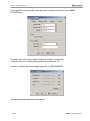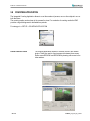
1
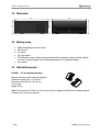
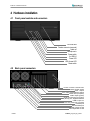
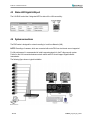
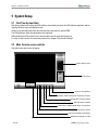
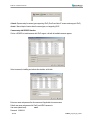
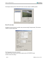
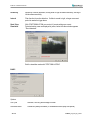
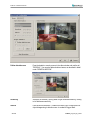
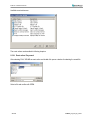
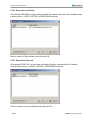
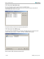
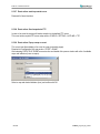
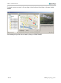
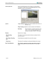
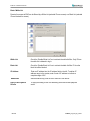
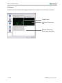
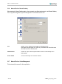
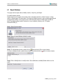
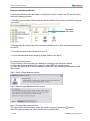
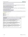
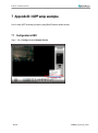
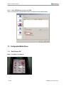
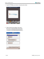
Installation Manual ENR 400 Network Video Recorder ENR 400 Installation Manual Safety Precautions • • To avoid any damage, please consider the following safety warnings: Never place the recorder near to heaters, furnaces, other heat sources or under direct solar irradiation. Operate the device only in locations providing the tolerable operating temperature range 0°C~40°C/32°F ~ +104°F. Make sure that the device‘s ventilation slots are not covered or sheeted. For cleaning, make sure the device is plugged off and only use a damp cloth without acid detergent. Install the device only in dry and dustproof surroundings. Protect the device against any liquid‘s penetration. Avoid the penetration of any artefacts, e.g. through ventilation slots. Do not attempt to disassemble the appliance. To prevent electric shock, do not remove screws or covers. There are no user-serviceable parts inside. Contact qualified service personnel for maintenance. Handle the appliance with care. Do not strike or shake, as this may damage the appliance. Do not operate appliance with other than specified power supplies. The input power source of the power supply is 100 ~ 240 VAC. Avoid any affection of the device through vibrations or mechanical shock at the recorder‘s installation location. Avoid to power off NVR by the backside power switch or disconnecting power cable during operation. • • • • • • • • • ATTENTION! This is a class A product which may cause radio interference in a domestic environment; in this case, the user may be urged to take adequate measures. This Product is RoHS compliant. WEE E Your EverFocus product is designed and manufactured with high quality materials and components which can be recycled and reused. This symbol means that electrical and electronic equipment, at their end-of-life, should be disposed of separately from your household waste. Please, dispose of this equipment at your local community waste collection/recycling centre. In the European Union there are separate collection systems for used electrical and electronic product. Please, help us to conserve the environment we live in! Ihr EverFocus Produkt wurde entwickelt und hergestellt mit qualitativ hochwertigen Materialien und Komponenten, die recycelt und wieder verwendet werden können. Dieses Symbol bedeutet, dass elektrische und elektronische Geräte am Ende ihrer Nutzungsdauer vom Hausmüll getrennt entsorgt werden sollen. Bitte entsorgen Sie dieses Gerät bei Ihrer örtlichen kommunalen Sammelstelle oder im Recycling Centre. Helfen Sie uns bitte, die Umwelt zu erhalten, in der wir leben! The information in this manual was current upon publication. The manufacturer reserves the right to revise and improve his products. Therefore, all specifications are subject to change without prior notice. Misprints reserved. Please read this manual carefully before installing and using this unit. Be sure to keep it handy for later reference. 2 of 81 ENR400_ma_inst_en_rev01 ENR 400 Installation Manual CONTENT 1 INTRODUCTION ..................................................................................................................................... 5 2 MAIN FEATURES ................................................................................................................................... 5 3 SPECIFICATIONS .................................................................................................................................. 6 3.1 3.2 3.3 3.4 3.5 4 TECHNICAL DATA.................................................................................................................................. 6 SUPPORTED CAMERA MODELS* ............................................................................................................ 7 DIMENSIONS ........................................................................................................................................ 8 DELIVERY SCOPE ................................................................................................................................. 8 OPTIONAL ACCESSORIES ...................................................................................................................... 8 HARDWARE INSTALLATION ................................................................................................................ 9 4.1 4.2 4.3 4.4 5 FRONT PANEL CONTROLS AND CONNECTORS ......................................................................................... 9 BACK PANEL CONNECTORS .................................................................................................................. 9 STATUS LED GIGABIT LAN PORT ........................................................................................................ 10 SYSTEM CONNECTIONS ....................................................................................................................... 10 SYSTEM SETUP................................................................................................................................... 11 5.1 5.2 5.3 5.4 FIRST TIME SYSTEM START ................................................................................................................ 11 MAIN CONSOLE SCREEN CONTROLS..................................................................................................... 11 QUICK START SETUP.......................................................................................................................... 12 DETAILED SETUP ............................................................................................................................... 18 5.4.1 5.4.2 5.4.3 5.4.4 5.4.5 5.4.6 5.4.7 5.4.8 5.4.9 5.5 5.5.1 5.5.2 5.6 5.6.1 5.6.2 5.6.3 5.6.4 5.7 5.8 5.9 COUNTING APPLICATION ............................................................................................................. 59 NETWORK SERVICES .......................................................................................................................... 61 5.9.1 5.9.2 5.9.3 5.9.4 5.9.5 5.9.6 5.9.7 6 Setting - General ........................................................................................................................................................... 18 Setting - Camera ........................................................................................................................................................... 20 Setting - I/O Device ....................................................................................................................................................... 26 Setting - PTZ - Config .................................................................................................................................................... 27 Setting - Hotline (communication settings) ................................................................................................................... 28 Setting - User Account .................................................................................................................................................. 29 Setting - Address book .................................................................................................................................................. 30 Setting - Monitor display ................................................................................................................................................ 30 Setting - Joystick ........................................................................................................................................................... 31 GUARD - LIVE EVENT / EVENT ACTION CONFIGURATION ........................................................................ 33 Event types.................................................................................................................................................................... 34 Event actions ................................................................................................................................................................. 46 SCHEDULE SETUP .............................................................................................................................. 52 Setup new schedule manually....................................................................................................................................... 53 Copy Schedule .............................................................................................................................................................. 54 3.5 Week Mode ............................................................................................................................................................. 54 Conigure - Encoding Option Panel ............................................................................................................................... 56 E-MAP .............................................................................................................................................. 57 Network service: Live Streaming ................................................................................................................................... 61 Network Service: Remote Playback .............................................................................................................................. 64 Network Service: Remote Playback .............................................................................................................................. 65 Network Service: Remote Playback .............................................................................................................................. 67 Network Service: 3GPP Service .................................................................................................................................... 68 Network Service: Remote Desktop ............................................................................................................................... 69 Network Service: Central Management......................................................................................................................... 69 APPENDIX A: DB TOOL ...................................................................................................................... 70 6.1 6.2 3 of 81 REPAIR DATABASE ............................................................................................................................. 71 EXPORT CONFIGURATIONS ................................................................................................................. 74 ENR400_ma_inst_en_rev01 ENR 400 Installation Manual 7 APPENDIX B: 3 GPP SETUP EXAMPLES .......................................................................................... 75 7.1 7.2 CONFIGURATION IN ENR .................................................................................................................... 75 CONFIGURATION MOBILE PHONE ......................................................................................................... 76 7.2.1 7.2.2 8 BenQ-Siemens E81 ....................................................................................................................................................... 76 BenQ P50 ...................................................................................................................................................................... 78 APPENDIX C: INSTALLATION REMOTE DESKTOP TOOL............................................................... 81 4 of 81 ENR400_ma_inst_en_rev01 ENR 400 Installation Manual 1 Introduction The NeVio ENR network video recorders are designed for recording and managing of IP video devices. Easy and intuitive operation, combined with intelligent search functions guarantee a fast an efficient evaluation of video records. The compatibility to many IP cameras of other manufacturers allow the installation of the ENR range in a wide range of security applications. 2 Main Features 5 of 81 Management of up to 32 channels from Megapixel cameras, IP cameras and video servers Multi-brand IP product support Local and remote PTZ control Digital PTZ Bidirectional audio I/O control of IP-Video devices Multi-Language support Dual monitor support Integrated video analytics Integrated counting application System and event log database Support for EKB-200 USB Joystick 3GPP live view support Easy installation with automatic camera search ENR400_ma_inst_en_rev01 ENR 400 Installation Manual 3 Specifications 3.1 Technical data Physical IP video channels Recording / playback rate Total recording rate Boost record function View modes Recording resolution Compression method Audio Internal HDD Video export Network interface Further interfaces Alarm I/O Monitor output Power Ambient temperature Housing Dimensions (WxHxD) Weight Functionality General / System Menu language support E-Map Monitor output System monitor Database management Functionality / Live View Video analytics PTZ Functionality / Recording Recording methods Schedule Recording rates Functionality / Playback Multi-channel playback Search functions Video enhancement Video export Video backup Functionality / Remote Access Remote video access methods 4 (expandable up to 32 with 7 x ENR U4) Up to 25 IPS / channel Up to 400 IPS in 4CIF resolution, up to 800 IPS in CIF resolution (depending on camera type / compression settings/method) // up to 85 MBit/s total input stream Event recording with adjustable quality and frame rate 1/4/6/9/10/13/16/25/36 (depending on number of installed licenses) Up to 1280 x 1024 H.264 / MJPEG / MPEG4 Bidirectional transmission, 1 audio channel per video channel (depending on IP device specification) Up to 4 x 8,9 cm (3,5”) SATA recording HDD + 1 system HDD Internal DVD-RW drive, USB 2.0 interface 1.000 Mbit/s, RJ45, standards IEEE 802.3, IEEE 802.3u, IEEE 802.3ab, IEEE 802.3x USB2.0 6 x, PS2 keyboard/mouse Support of I/O contacts of connected IP devices (depending on IP device specification) 1 x VGA out, 1 x VGA/DVI out, dual monitor operation possible; supported GUI resolutions 1024x768, 1200x900, 1280x1024, 1600x1200 110 ~ 230 V AC, 300 VA max. 0°C ~ +40°C Steel, aluminium front, black 430 x 171,5 x 439,6 mm, 19”, 4U, optional 19" mounting brackets available 11 kg Danish, English, German, Finnish, French, Greek, Italian, Japanese, Korean, Portuguese, Russian, Slovakian, Spanish, Thai, Czech, Turkish, Hungarian, Chinese Unlimited number of maps or other graphics with free placement of camera or I/O icons GUI in 4:3 format; dual monitor support, 2nd monitor can be used for additional live and/or playback view Permanent monitoring of CPU load / temp., memory, network load, HDD usage with log and display function Integrated tool for database reconstruction, repair or relocation; export option for configuration file General motion, missing object, camera occlusion, foreign object, lose focus, signal lost each alarm can trigger up to 10 different event reactions PTZ control in OSD or with EKB 200 joystick for PTZ cameras; digital software PTZ for all cameras Continuous, schedule, event (motion / contact) Individual for each camera, daily schedule with 6 possible recording modes 1~25 IPS adjustable for each camera (depending on camera specification) Up to 16 channels time-synchronized Time / Date via calendar and time bar; intelligent search with modes general motion, missing object, camera occlusion, foreign object, signal lost Saturation, contrast, brightness, sharpness Snapshot in JPEG format, video export in AVI or ASF format Backup of multiple camera video data to local / network video drive or CD/DVD Max. number of remote video channel access Remote maintenance 6 of 81 Remote client software live view (up to 2 windows with up to 16 x view each at 1 PC) , Remote client software playback view (up to 16 x view) with remote backup function (multiple channel backup up to 16 channels) Web browser (live / playback with up to 16 x view), 3G mobile phone client (rtsp streaming support required); Unlimited number of installations for all remote applications 128 video channels total Remote desktop viewer allows complete network access to ENRxx NVR (1 monitor display only supported) including configuration ENR400_ma_inst_en_rev01 ENR 400 Installation Manual 3.2 Supported Camera Models* Supported IP Cameras / Video server Status: Version 3.1.4.7 / October 20109 Manufacturer Supported Products EverFocus EAN800A*; EAN800AW*; EAN850A*; EAN900*; EDN800*; EDN850*; EZN850*; EVS100; EVS400; EAN750 SED 2100; SED 2120; SED 2140; SED 2310; SED 2320; SED 2400; SED 2420; SED 2600; SED 2610; SEM 1110; CAM 5130; CAM 5140; CAM 5150; CAM 5200; CAM 5201; CAM 5221: CAM 5300; CAM 5301; CAM 5321; CAM 5500; CAM 6100; CAM 6200; CAM 6220; CAM 6500; CAM 6510; CAM 6520; CAM 6600; CAM 6610; CAM 6620; CAM 6630; CAM 7100; CAM 7120;CAM 7200; CAM 7220; CAM 7300; CAM 7301; CAM 7320; CAM 7321; CAM 7322; ACD 2100; ACD 2200; ACD 2300; ACD 2400; ACM 1011; ACM 1231; ACM 1311; ACM 1431; ACM 1432; ACM 3001; ACM 3211; ACM 3311; ACM 4100; ACM 4200; ACM 5001; ACM 5601, ACM 5611; ACM 5711; ACM 7411; ACM 8511;TCM 4301*; TCM 5311* AV1300; AV1305*; AV2000; AV2100; AV2105*; AV2155*; AV3100; AV3105*; AV3130; AV5100; AV5105*; AV8180; AV8360; A02-OIPCAM1; A02-OIPCAM2; A02-OIPCAM3; A02-IPCAM5; A02-IPCAM6; A02-IPCAM7; A02-IPCAM8; A02-IPCAM9; A02IPCAM10; A02-IPCAM11; A02-IPCAM12; A02-IPCAM13; A02-IPCAM14; A02-IPCAM15; A02-IPCAM16; A02-IPCAM17; 205; 206; 206M; 206W; 207; 207W; 207MW; 209FD; 209FD-R; 209MFD; 209MFD-R; 210; 210A; 211; 211A; 211M; 211W; 212; 213; 214; 215; 216FD; 216FD-V; 216MFD; 216MFD-V; 221; 223M; 225FD; 231D; 231D+; 232D; 232D+; 233D; 240Q; 241Q; 241QA; 241S; 241SA; 242S; 243Q; 243SA; 247S; 2460; M1011*; M1011-W*; M1031-W*; p3301*; p3301V*; Q1755*; Q7401*; Q7406Blade* PVC300 DCS-6620; DCS-6620G; DCS-5220; DCS-5300; DCS-5300G; DCS-2120; DCS-3420; DCS-3220; DCS-3220G; DCS-2100; DCS2100G; DVS-104; DVS-301; DCS-900; DCS-G900; DCS-910; DCS-920; DCS-950; DCS-950G; DCS-3110; DCS-3410; DCS-3415; DCS-5220(TW); DCS-5610; DCS-6110; DCS-6111; nZH06X; nZH10X; nZH21X TCP-690; TCP-690DN; TCP-HP930; WB-8211SD; WB-8411; CDV-3V930; TCP-690U; TCP-HP930U; WB-8211SDU; CDV-3V930U; EP-936; EP-908; EP-601; EP-201; EP-221; EP-221DN HNCB-E1SN; HNG-E1SAW0S4; HWD125MN; HECMC4V0C4 ICanView220; ICanView222; ICanView230; ICanView232; ICanView240; ICanView250; ICanView260; ICanView270; ICanView280; ICanView290; ICanserver510; IQeye301; IQeye301m; IQeye301w; IQeye302; IQeye302w; IQeye303; IQeye303w; IQeye501; IQeye510; IQeye511; IQeye601; IQeye602; IQeye603; IQeye701; IQeye702; IQeye703; IQeye705; IQeye751; IQeye752; IQeye753; IQeye755 VN-C20U; VN-E4(U); VN-C205U; VN-C215U; VN-C655U; FCS-0010; FCS-0020; FCS-1010; FCS-1030 V1.0; FCS-1030 V2.0; FCS-1040; FCS-1050; FCS-1060; FCS-1070; FCS-1081; FCS1081A; FCS-1091; FCS-1101; FCS-3000; FCS-3021; FCS-4010; FCS-5011; FCS-5030; FCS-7011; WCS-0010; WCS-0020; WCS1090; WCS-2060; WCS-2010 V1.0; WCS-2010 V2.0; WCS-2030 V1.0; WCS-2030 V2.0; WCS-2030 V3.0; WCS-2040; WCS-2070 PVC2300; WVC2300; WVC210 ACTI Arecont Atlantis Land Axis Cisco D-Link Dynacolor Fine Hitron IcanTek IQinVision JVC LevelOne Linksys Lorex Probe LNE3003 le045c; le045c-dn; le075c; le075c-dn; le165c; le165c-dn; le175c; le175c-dn; le259c; le275c; le275c-dn; le375c; le375c-dn; le11059c; Li165C-OV3 M10D-Night; M12D-Sec; M12D-IT-DNight; M12D-Sec-Dnight; M12D-Web; M22M-IT; M22M-Sec; M22M-Sec-Night; D12Di-IT; D12DiSec; D22M-IT-Night; M12D-SEC-Dnight-D43N43; Q22M-SEC-D11 Vport 25; Vport 251; Vport 254; Vport 351 BB-HCM311; BB-HCM331; BB-HCM371; BB-HCM381; BB-HCM403; BB-HCE481; BB-HCS301; BB-HCM511; BB-HCM515; BBHCM527; BB-HCM531; BB-HCM581; BL-C10; BL-C1; BL-C20; BL-C30; BL-C111; BL-C131; KX-HCM110; KX-HCM280A; WJNT304; WJ-NT314; WV-NP1000; WV-NP1004; WV-NM100; WV-NP240; WV-NP244; WV-NS202; WV-NW484; WV-NS954; WVNS950; WV-NW964; WV-NW484S 100; 120/126/128; 200/206; 201; 205; 207; 240; 241; 261; 262; 263; 300; 400/42X; 461; 463; 1000; 1401; 2000: 4000; 405; 410; 405M; 411/412 ICA-510; ICA-700; ICA-151W; ICA-151; ICA-750; ICA-107W; ICA-107P; ICA-107; ICA-108; ICA-108W; ICA-120; ICA-230; ICA230W; ICA-230P; ICA-M230; ICA-310; ICA-310W; ICA-312; ICA-312v2; ICA-350; ICA-350-V2; ICA-501; ICA-525; ICA-530; ICA-651; ICA-601; IVS-110 IP fixed camera, IP PTZ camera Samsung Electronics C6475 Seorim Toshiba SVC-3030/41NR-DN; SVG-3110; SVG-3410; SVD-3020-PT Z; SVD-3020; SNC-CS3; SNC-Z20; SNC-RZ30; SNC-CS10; SNC-CS11; SNC-DF40; SNC-DF70; SNC-P1; SNC-P5; SNC-RZ25; SNC-CS50; SNC-DF50*; SNC-DF80*; SNC-RX530*; SNC-RX550*; SNC-RX570*; SNC-RZ50; SNT-V704; SNC-CM120; SNC-DM110; SNCDM160; SNC-CS20; SNC-DS10; SNC-DS60 IK-WB02A; IK-WR01A; IK-WB21A; IK-WB15A Truen TCS-200 Lumenera Mobotix Moxa Panasonic Pixord Planet Sony * For a complete list of supported IP products, please refer to the current “ENR Product List”. 7 of 81 ENR400_ma_inst_en_rev01 ENR 400 Installation Manual 3.3 Dimensions 3.4 Delivery scope ENRxxx depending on ordered version PC keyboard PC mouse DVI-VGA adaptor CD-ROM with recovery software, remote software and documentation (software includes: Remote Live Client, Remote Playback Client, Database Maintenance Tool, Backup Software) User manual 3.5 Optional Accessories BA RK01 – 19” rack mounting brackets Material: aluminium handle, steel mounting plate Dimensions handle (LxD): 115 x 40 mm Dimensions (WxLxD): 24 x 135 x 95 mm Colour: black Weight: 200 g Note: The brackets are for fixation in 19" rack only. Due to the weight of the ENR device, additional support brackets for the 19" rack are required! 8 of 81 ENR400_ma_inst_en_rev01 ENR 400 Installation Manual 4 Hardware installation 4.1 Front panel controls and connectors DVD-RW drive Firewire-connector (reserved) Audio out Microphone in Power switch 2 x USB 2.0 Power LED HDD Access LED Reset switch 4.2 Back panel connectors Power in socket 110/230 VAC Mains Power switch VGA - Output DVI / VGA (with adapter) Output Audio line input (blue) Audio output (green) Audio microphone input (pink) LAN (RJ45) port, Gigabit interface USB 2.0 port 4 x VGA out (reserved, not used) Parallel port Serial RS232 port PS/2 mouse socket PS/2 keyboard socket 9 of 81 ENR400_ma_inst_en_rev01 ENR 400 Installation Manual 4.3 Status LED Gigabit LAN port The LAN RJ45 socked has 2 integrated LED for status of the LAN connectivity: 4.4 System connections The ENR series is designed for network recording in Local Area Network (LAN). NOTE: Recordings of cameras, which are connected with router/DSL lines via internet are not supported For full performance it is recommended to install a separate network for the IP video security system. Further on the LAN connection between network switch and EVR should support Gigabit network transmission. The following figure shows a typical installation: 10 of 81 ENR400_ma_inst_en_rev01 ENR 400 Installation Manual 5 System Setup 5.1 First Time System Start With factory default user settings the ENR will boot automatically and starts the ENR software application without requiring Windows Login and Application login. Switch on the backside power switch and push the front power switch to start the ENR. The ENR application starts with administrator user right level. With this setting the ENR will also recover record mode in case of restart after power loss. For setup of user accounts incl. passwords please refer to chapter "User Account Settings". 5.2 Main Console screen controls After start-up the main screen will appear: Status display area PTZ control System configuration "Guard" mode setup (live monitoring events) Scheduled recording setup Start Playback window Start: Start / disable application components Sequence mode Fullscreen display (frameless) Multiscreen display modes 11 of 81 ENR400_ma_inst_en_rev01 ENR 400 Installation Manual 5.3 Quick Start Setup This chapter describes the minimum installation steps to install IP-cameras for standard (continuous) recording. Note: Precondition for this quick start setup is that all IP cameras of the system are installed in the same network and IP address range as the ENR. The default IP setting of the ENR is DHCP mode with alternative IP setting (if the network doesn’t support DHCP): IP: 192.168.1.100 Subnet mask: 255.255.0.0 1. Open camera setup menu >CONFIG > SETTING > tab CAMERA: After selecting the tab CAMERA, the screen shows the camera setup with an empty camera list. The camera setup supports 2 methods to install cameras: 12 of 81 ENR400_ma_inst_en_rev01 ENR 400 Installation Manual +Search: Express setup for camera types supporting UPnP. (EverFocus Nevio IP camera series support UPnP). +Insert: Manual input of camera data for camera types, not supporting UPnP. Camera setup with SEARCH function Click on +SEARCH to install cameras with UPnP support, a list with all available cameras appears: Select a camera for installing and activate the checkbox at left side: Enter user name and password for this camera and if applicable the camera name. Default user name and password for EverFocus NEVIO cameras is: User name (admin level): user1 Password: 11111111 13 of 81 ENR400_ma_inst_en_rev01 ENR 400 Installation Manual After setting the desired cameras confirm with OK to take over these cameras in the ENR camera list: Manual IP camera setup Alternative to the search function it is possible to setup cameras including IP settings manually. Click the button +INSERT to open the setup window: Enter IP parameter and user name / password. Under DEVICE select a listed vendor and camera model or use the AUTO DETECT function. Click OK to take over the settings. 14 of 81 ENR400_ma_inst_en_rev01 ENR 400 Installation Manual For changing frame rate and recording image quality select a camera from the list and press CAMERA SETTINGS button: The window shows current camera settings. Possible values depend on camera type. Change the setting to the recording system requirements and confirm with OK. Optional it is possible to adjust camera display setting, click on VIDEO PARAMETER: After adjusting the display parameters confirm with OK. 15 of 81 ENR400_ma_inst_en_rev01 ENR 400 Installation Manual On lower right side of camera setup screen are additional settings for On Screen Display overlay display: OSD on/off OSD of date / date adjustment OSD of time / time adjustment OSD camera number OSD camera name OSD bitrate of single camera OSD font settings Apply selection to all listed cameras If all settings are done, confirm with OK in CAMERA setup menu. Minimum settings in GENERAL menu. Open camera setup menu >CONFIG > SETTING > tab GENERAL: 1. Please double-check, that all recording HDD are entered correctly under LOCATION. These drives are entered already by factory depending on order (1 to 4 HDD). 2. Check and adjust the other important recording settings: Automatic Recycle: with activated checkbox the ENR will delete oldest records, if the recording HDD are filled. Recycle Range: interval (1h to 1 day), how often ENR checks for deleting old records Keep Video: If activated, the ENR will delete video data after a defined time period. If not activated, the ENR will use full HDD capacity for achieving max. recording time. 16 of 81 ENR400_ma_inst_en_rev01 ENR 400 Installation Manual If recording shall start automatically after application start, activate the checkbox SCHEDULE RECORDING SYSTEM under START-UP. Confirm all settings with OK. With these basic settings the ENR is configured already for continuous recording. For more detailed settings including schedule and event management refer to the following chapters DETAILED SETUP. Finally check under > Start, that RECORDING SCHEDULE is activated. The system will record now, recording is indicated by a red point in each recording video channel. 17 of 81 ENR400_ma_inst_en_rev01 ENR 400 Installation Manual 5.4 Detailed Setup Following chapters describe the setup options of the ENR in all details. 5.4.1 Setting - General open with > CONFIG > SETTING This menu defines general parameters, display and start-up behaviour of the ENR. Start-up - Behaviour of ENR after booting Main Console: Smart Guard System: Counting application: 18 of 81 with activated checkbox the ENR application starts automatically after Windows start with activated checkbox the life event management will be activated at ENR start with activated checkbox the counting application will be activated at ENR start ENR400_ma_inst_en_rev01 ENR 400 Installation Manual Live streaming server: Remote playback server: 3GGP server: Remote desktop server: Central management service: Full screen: Auto login: with activated checkbox the steaming server for live view will be activated at ENR start with activated checkbox the steaming server for playback view will be activated at ENR start with activated checkbox the 3GGP mobile phone server will be activated at ENR start with activated checkbox the remote desktop server will be activated at ENR start reserved with activated checkbox the ENR application will start in full screen mode with activated checkbox the ENR application requires no manual login. Storage - Settings for storage location and general recording parameters Location Automatic Recycle Recycle range Keep video Keep event log Keep system log Keep counting log Keep POS transaction List of recording HDD and recording path. Please check, if all drives are listed. with activated checkbox the ENR will delete oldest records, if the recording HDD are filled. interval (1h to 1 day), how often ENR checks for deleting old records If activated, the ENR will delete video data after a defined time period. If not activated, the ENR will use full HDD capacity for achieving max. recording time. If activated, the ENR will delete event log data older than the entered value in days If activated, the ENR will delete system log data older than the entered value in days If activated, the ENR will delete counting log data older than the entered value in days reserved Audio Preview - Live monitoring audio settings Default channel Enable Audio Channel Volume 19 of 81 on Select the audio channel, which is active in any multi-view without selecting a camera in this view Active If activated, Audio output will change to selected camera channel Audio output volume ENR400_ma_inst_en_rev01 ENR 400 Installation Manual Status Display - Display options for global status display (right side of main screen) Display options, displayed with activated checkbox Current time Current date Free disk space (total for all recording drives) IP camera bitrate (summarised input stream) CPU Temperature (not supported) CPU fan speed (not supported) User defined text 1 (free editable) User defined text 2 (free editable) Auto reboot With activated checkbox the system will reboot in defined time interval. If you use this function, make sure to activate under START-UP: Main console Schedule recording system Auto login Otherwise the recording function will not recover automatically after reboot. 5.4.2 Setting - Camera 1. Open camera setup menu >CONFIG > SETTING > tab CAMERA: 20 of 81 ENR400_ma_inst_en_rev01 ENR 400 Installation Manual After selecting the tab CAMERA the screen shows camera setup with an empty camera list. The camera setup supports 2 methods to install cameras: +Search: Express setup for camera types, which support UPnP. (EverFocus Nevio IP camera series support UPnP). +Insert: Manual input of camera data for camera types, which have no UPnP support. Camera setup with SEARCH function Click on +SEARCH to install cameras with UPnP support, a list with all available cameras appears: 21 of 81 ENR400_ma_inst_en_rev01 ENR 400 Installation Manual Select a camera for installing and activate the checkbox at left side: Enter user name and password for this camera and if applicable the camera name. Default user name and password for EverFocus NEVIO cameras is: user name (admin level): user1 password: 11111111 After setting the desired cameras confirm with OK to take over these cameras in the ENR camera list: 22 of 81 ENR400_ma_inst_en_rev01 ENR 400 Installation Manual Manual IP camera setup Alternative to the search function it is possible to setup cameras including IP settings manually. Click the button +INSERT to open the setup window: Enter IP parameter and user name / password. Under DEVICE select a listed vendor and camera model or use the AUTO DETECT function. Click OK to take over the settings. 23 of 81 ENR400_ma_inst_en_rev01 ENR 400 Installation Manual For changing frame rate and recording image quality select a camera from the list and press CAMERA SETTINGS button: The window shows current camera settings. Possible values depend on camera type. Change the setting to the recording system requirements and confirm with OK. Optional it is possible to adjust camera display setting, click on VIDEO PARAMETER: After adjusting the display parameters confirm with OK. 24 of 81 ENR400_ma_inst_en_rev01 ENR 400 Installation Manual On lower right side of camera setup screen are additional settings for On Screen Display overlay display: OSD on/off OSD of date / date adjustment OSD of time / time adjustment OSD camera number OSD camera name OSD bitrate of single camera OSD font settings Apply selection to all listed cameras If all settings are done, confirm with OK in CAMERA setup menu. 25 of 81 ENR400_ma_inst_en_rev01 ENR 400 Installation Manual 5.4.3 Setting - I/O Device This menu defines parameters for digital inputs and outputs of connected IP devices. The functionality depends on connected IP - devices. Device name List of available devices Input / Output list Input monitor Output simulator Module Setting Device name of selected IP device (as defined in CAMERA menu) Add, Modify, Remove, Device, Com port, ID reserved functions for IP-serial converters Device list List with available IP-devices, which provide I/O function Digital Input Monitor The selected input is turned on if the dot is in red. By triggering the digital input device, the related icon will light up. This is used to check if the device is correctly connected or not. Digital Output Simulation The selected output is turned on if the dot is in red. By clicking on the icon, you may trigger the digital device connecting to the system. This can be used to test if the output device is correctly connected. Digital input/output pins of selected I/O module Name Type N/O N/C 26 of 81 Define the name of the device (input and output). Select the device type from the drop-down menu. Normal Open. Normal Close. ENR400_ma_inst_en_rev01 ENR 400 Installation Manual 5.4.4 Setting - PTZ - Config Camera list Communication settings PTZ parameter Tour settings Preset settings Camera list Available cameras in the system. Select one and activate checkbox for editing PTZ functions. Basic settings Select the device type from the drop-down menu. Com port not supported in ENR, greyed Baud rate Address Advanced setting Speed setting for PTZ and Autopan (functionality depends on camera model) Patrol group Submenu for defining preset tours of this camera, 4 tours are available User defined preset 27 of 81 For creating a tour insert available presets from left list, adjust dwell time and turn on the checkbox "Active". Submenu for defining presets for special functions (depending on PTZ camera) ENR400_ma_inst_en_rev01 ENR 400 Installation Manual 5.4.5 Setting - Hotline (communication settings) This menu provides communication settings for mail, FTP, modem and phone. These settings are mandatory for several alarm reactions in GUARD mode (Send Snapshot to FTP, Phone call, Send SMS, Send e-mail). E-mail Input the following information: server, sender’s E-mail address, E-mail’s subject title, and body content. You may click on the Send Test Mail button to test the settings. Note: * indicates mandatory areas FTP Input the following information: server, Port, Login ID, Password, and Upload directory. According your FTP type to enable/disable Passive mode. You may click on the Upload Test File button to test the settings. Note: * indicates mandatory areas. Telephone Select the modem that the system is going to dial the info call with, and then insert the phone number. (A modem is required for voice transition.) 1. You must use a modem with voice capability. 2. You may select a Wave format file; it will be played in the phone to alarm the person who picks up the phone call. Set the Port and Baud Rate of the GSM modem device, and then enter PIN code. You can setup the interval of send SMS message. You may click on Test to send test SMS message. Note: The interval is set to restrict the period of two SMS. If you set as 60 min, the SMS between 60 min would be deleted and didn’t send to user. Note GSM modem 28 of 81 ENR400_ma_inst_en_rev01 ENR 400 Installation Manual 5.4.6 Setting - User Account The ENR recorders provide user right management with free assignable user rights for each user. In factory setting 1 user with administrator rights is pre-defined: user name: admin no password For user setup are 2 groups of user rights defined: Admin: all user rights (user rights can not be unchecked, for defining Administrators with limited user rights user the group USER) User: user group with free assignable user rights per user Factory settings: enabled: Main console, Live view, Playback View, Remote live view, all others disabled Add Creates new user account. Enter name, description and password and define the user rights. Then click on ADD to create the account. Delete Select an account from the list on right side and click on DELETE to remove this account. Modify Select and account from the list on right side. Modify name / description / password and click on MODIFY for taking over the changes. Disable Deactivates a selected account without deleting the account. 29 of 81 ENR400_ma_inst_en_rev01 ENR 400 Installation Manual 5.4.7 Setting - Address book Contact person settings are required for GUARD mode event reactions "Phone call", "Send SMS" and "Send mail". Enter the required data. Already defined contact persons are listed in lower part of the window. 5.4.8 Setting - Monitor display Monitor selection for Playback Available cameras List of cameras, displayed on selected screen Auto scan settings Layout for multiview type "N" 30 of 81 ENR400_ma_inst_en_rev01 ENR 400 Installation Manual Run Playback on Monitor Selection of monitor output 1 or 2 for playback window Primary / Secondary Use the arrow buttons in the middle to add / remove cameras from the list of selected monitor. Removed cameras will not be displayed at this monitor. Auto scan Primary channel "Not used" will scan all channels, which are assigned to primary monitor in order. If a channel is selected, this channel will be displayed every second step. Example: "Primary Channel: Ch. 3": Sequence: 1 > 3 > 2 > 3 > 4 > 3 > 5 > 3 > 6...... Secondary channel "Not used" will scan all channels, which are assigned to secondary monitor in order. If a channel is selected, this channel will be displayed every second step. Example: "Primary Channel: Ch. 3": Sequence: 1 > 3 > 2 > 3 > 4 > 3 > 5 > 3 > 6...... Auto scan interval Dwell time for interval switching in seconds Layout NxN type Layout for the free definable multiview "N": 4x4, 5x5 or 6x6 Popup camera on Event If checkbox is active, cameras will switch to full screen in case of live events. Note: If secondary monitor is used, make sure to enable this monitor under > START > ENABLE SECONDARY DISPLAY 5.4.9 Setting - Joystick The ENR series supports EKB-200 joysticks and other HID compatible USB Joysticks. If the system detected a joystick, ENR will show the setup options under the tab JOYSTICK. Without connected joystick the options are greyed and not active. 31 of 81 ENR400_ma_inst_en_rev01 ENR 400 Installation Manual Selectable options for key assignment of the Joystick are: 32 of 81 ENR400_ma_inst_en_rev01 ENR 400 Installation Manual 5.5 GUARD - live event / event action configuration The GUARD mode allows live monitoring with automatic event reactions, triggered by intelligent video analytics functions. For the settings click on GUARD in Main screen: The menu screen shows all installed systems in the left side list, which can be used as event source. For defining an event select a device from the list and open with right click > NEW the context menu. 33 of 81 ENR400_ma_inst_en_rev01 ENR 400 Installation Manual 5.5.1 Event types Depending on the device you will get a choice of available event types: For cameras: For input contacts: 34 of 81 ENR400_ma_inst_en_rev01 ENR 400 Installation Manual For system events: The setup options for the event types are described in following chapters 35 of 81 ENR400_ma_inst_en_rev01 ENR 400 Installation Manual 5.5.1.1 Signal lost event Indicates signal loss from this camera. Options: Life Cycle Definition, how long the message is shown Activated Period Permanent (Always Activated) or scheduled function (daily time period) 36 of 81 ENR400_ma_inst_en_rev01 ENR 400 Installation Manual 5.5.1.2 General motion event The GENERAL MOTION event allows motion detection in free definable square detection areas. ADVANCED For defining a detection area draw a window by mouse in the video window. Confirm setting with "REGION1". You can add more detection areas by drawing in the video window and confirming by "REGION1". Cutting out areas from detection zones is possible by confirming with "SUBTRACT": 37 of 81 ENR400_ma_inst_en_rev01 ENR 400 Installation Manual Sensitivity Sensitivity of motion detection, moving slider to right increases sensitivity, moving to left decreases sensitivity. Interval Filter function for motion detection. If slider is moved to right, a longer movement period is needed to trigger alarm Start / Stop Simulation With START SIMULATION you can test, if current settings are correct. Detected motion areas are displayed in yellow, below the video window appears "Event detected". End the simulation mode with "STOP SIMULATION". BASIC Options: Life Cycle Definition, how long the message is shown Activated Period Permanent (Always Activated) or scheduled function (daily time period) 38 of 81 ENR400_ma_inst_en_rev01 ENR 400 Installation Manual 5.5.1.3 Foreign object event This event type creates an event if an unexpected object appears in a defined zone. Define detection zone Draw the detection zone by mouse in the video window and confirm wit "REGION1". You can also add and subtract areas, as described in detail under "GENERAL MOTION". Define object size Draw in the video window an area in the expected size of the object. 39 of 81 ENR400_ma_inst_en_rev01 ENR 400 Installation Manual Sensitivity Sensitivity of detection, moving slider to right increases sensitivity, moving to left decreases sensitivity. Interval Filter function for detection. If slider is moved to right, a longer period of object appearing in detection zone is needed to trigger alarm. Start / Stop Simulation With START SIMULATION you can test, if current settings are correct. Detected objects are displayed in yellow, below the video window appears "Event detected". End the simulation mode with "STOP SIMULATION". BASIC Options: Life Cycle Definition, how long the message is shown Activated Period Permanent (Always Activated) or scheduled function (daily time period) 5.5.1.4 Missing object event The event type MISSING OBJECT allows to monitor automatically objects in the camera field of view. Removing of the object will trigger an event. 40 of 81 ENR400_ma_inst_en_rev01 ENR 400 Installation Manual Define detection zone Draw the detection zone by mouse in the video window and confirm wit "REGION1". You can also add and subtract areas, as described in detail under "GENERAL MOTION". Sensitivity Sensitivity of detection, moving slider to right increases sensitivity, moving to left decreases sensitivity. Interval Filter function for detection. If slider is moved to right, a longer period of object disappearing in detection zone is needed to trigger alarm. 41 of 81 ENR400_ma_inst_en_rev01 ENR 400 Installation Manual Start / Stop Simulation With START SIMULATION you can test, if current settings are correct. Detected movements are displayed in yellow, below the video window appears "Event detected". End the simulation mode with "STOP SIMULATION". BASIC Options: Life Cycle Definition, how long the message is shown Activated Period Permanent (Always Activated) or scheduled function (daily time period) 42 of 81 ENR400_ma_inst_en_rev01 ENR 400 Installation Manual 5.5.1.5 Camera occlusion event Sensitivity Sensitivity of detection, moving slider to right increases sensitivity, moving to left decreases sensitivity. Interval Filter function for detection. If slider is moved to right, a longer period of camera occlusion is needed to trigger alarm. Ignore Lighting change With activated checkbox the event will not trigger, if a global light change (turn light on / off) appears in the camera picture. Start / Stop Simulation With START SIMULATION you can test, if current settings are correct. Below the video window appears "Event detected". End the simulation mode with "STOP SIMULATION". 43 of 81 ENR400_ma_inst_en_rev01 ENR 400 Installation Manual BASIC Options: Life Cycle Definition, how long the message is shown Activated Period Permanent (Always Activated) or scheduled function (daily time period) 44 of 81 ENR400_ma_inst_en_rev01 ENR 400 Installation Manual 5.5.1.6 Focus lost event Sensitivity Sensitivity of detection, moving slider to right increases sensitivity, moving to left decreases sensitivity. Interval Filter function for detection. If slider is moved to right, a longer period of unfocussed camera is needed to trigger alarm. Ignore Lighting change With activated checkbox the event will not trigger, if a global light change (turn light on / off) appears in the camera picture. Start / Stop Simulation With START SIMULATION you can test, if current settings are correct. Below the video window appears "Event detected". End the simulation mode with "STOP SIMULATION". 45 of 81 ENR400_ma_inst_en_rev01 ENR 400 Installation Manual BASIC Options: Life Cycle Definition, how long the message is shown Activated Period Permanent (Always Activated) or scheduled function (daily time period) 5.5.2 Event actions Each defined event can be assigned to one ore more event actions. Select an event at left side list and click on "INSERT ACTION" or open context menu by right click and select NEW: 46 of 81 ENR400_ma_inst_en_rev01 ENR 400 Installation Manual Available event actions are: The event actions are described in following chapters. 5.5.2.1 Event action: Play sound After selecting PLAY SOUND as event action and double click opens a window for selecting the sound file. Select a file and confirm with OPEN. 47 of 81 ENR400_ma_inst_en_rev01 ENR 400 Installation Manual 5.5.2.2 Event action: Send E-mail After selecting SEND E-MAIL as event action and double click opens a window with a list of available contact persons (setup in > CONFIG > SETTING > ADDRESS BOOK required): Select a contact for E-Mail notification and confirm with OK. 5.5.2.3 Event action: Phone call After selecting PHONE CALL as event action and double click opens a window with a list of available contact persons (setup in > CONFIG > SETTING > ADDRESS BOOK required): Select a contact for phone call notification and confirm with OK. 48 of 81 ENR400_ma_inst_en_rev01 ENR 400 Installation Manual 5.5.2.4 Event action: PTZ preset go This event requires PTZ cameras with preset function in the system. After selecting PTZ PRESET GO as event action and double click opens a window for selecting the PTZ camera, preset position and event related parameters. Confirm the entered values with OK. 49 of 81 ENR400_ma_inst_en_rev01 ENR 400 Installation Manual 5.5.2.5 Event action: Signal digital output This event action allows to switch a contact output of an installed IP-device. After selecting SIGNAL DIGITAL OUTPUT as event action and double click opens a window with all available digital output contacts in the system: Activated the checkbox at desired contact output and confirm with OK. 5.5.2.6 Event action: Send a SMS message After selecting SEND A SMS MESSAGE as event action and double click opens a window with a list of available contact persons (setup in > CONFIG > SETTING > ADDRESS BOOK required): Select a contact for SMS notification and confirm with OK. 50 of 81 ENR400_ma_inst_en_rev01 ENR 400 Installation Manual 5.5.2.7 Event action: send top central server Reserved for future functions 5.5.2.8 Event action: Send snapshot to FTP In case of an event the system will send a snapshot to the defined FTP server. This event action requires FTP-server setup under >CONFIG > SETTING > HOTLINE > FTP. 5.5.2.9 Event action: Popup e-map on event This event type allows display of an event in e-map (automatic popup). Required is a configuration of e-map under > START > E-MAP After selecting POPUP E-AP EVENT as event action and double click opens a window with a list of available maps and indicators (icons on maps): Select a map and desired indicator (icon) and confirm with OK. 51 of 81 ENR400_ma_inst_en_rev01 ENR 400 Installation Manual 5.6 Schedule setup The ENR allows continuous, scheduled or event controled recording. The recording behaviour is defined in the SCHEDULE menu. Open the SCHEDULE menu from MAIN console: In factory setting the system will record all cameras in continuous mode. 52 of 81 ENR400_ma_inst_en_rev01 ENR 400 Installation Manual 5.6.1 Setup new schedule manually Step 1 Step 2 Step 3 Step 4 Step 1 Left-click and draw the bar to the time table. The scheduled time will appear as a grey bar. Step 2 Click the Insert icon and add a new schedule in the Regular Mode, i.e. to record video during the time period you set with 30 FPS, Normal video quality, and Normal resolution. Step 3 Change the setting if wished by clicking on the Configure icon (See 3.7 Encoding Option Panel) or double click the schedule information. Step 4 Click OK. 53 of 81 ENR400_ma_inst_en_rev01 ENR 400 Installation Manual 5.6.2 Copy Schedule You may set up the schedule for each channel/camera by repeating the process above, or simply apply the setting of a single camera to all the others. Copy To 5.6.3 3.5 Week Mode Schedule the cameras for each day of the week differently. In addition, you may assign extra holidays under the Week Mode. Default Holiday Custom Week Mode Default Follow the same process to setup the schedule for every day in a week. Holiday You may assign holidays where the system will work according to the setting of Sunday. Custom You can assign a particular date(s) on which the system will work according to a special schedule(s) different from the others. 54 of 81 ENR400_ma_inst_en_rev01 ENR 400 Installation Manual Adjust the Scheduled Setting: You can manually change the setting at any time after you insert or load a period of schedule. Option 1: Move the cursor to the Time Bar and change the length or move the bar sideway to change the start and end points. Time Bar Configure Schedule Information Option 2: Click on the Configure icon or double click on schedule information on the screen (highlighted in blue) to obtain the Encoding Option panel (next page) and change the setting as wished. Configure: Click on the configure icon to obtain the Encoding Option panel. 55 of 81 ENR400_ma_inst_en_rev01 ENR 400 Installation Manual 5.6.4 Conigure - Encoding Option Panel Select Event Panel Always Record Record on Event Record on Motion Pre-record/ Post-record Always Record Select this option to record the video at all time. Record on Event Select this option to obtain the Select Event panel. From the Smart Guard list, check the box of the camera(s) that you want to trigger the recording action. Click OK to complete the setting. Note: This option needs start Smart Guard to trigger the recording schedule. Record on Motion Select this option to start recording when there are motions detected. To detect Motion, you have to define a detection zone. Left-click and drag the mouse to draw a detection zone. You may define more than one zone on the screen by repeating the same process. User can also click on “All” button to select the entire detection zone. You may adjust the sensitivity and the frame interval. Pre-record/ Postrecord Time The pre-record/ post-record function saves the recording data accordingly. For instance, to set up a 5 second pre-record time means the system will start saving the recording data 5 seconds before the event happens. 56 of 81 ENR400_ma_inst_en_rev01 ENR 400 Installation Manual 5.7 E-Map The ENR series provides an e-map function, which allows to show location of installed IP - Devices on maps or other graphics. In GUARD mode the map can popup automatically in case of an event and show the event location including preview of the event camera. For setup of e-map go to > START > E-MAP. List of installed IP devices Map - area Preview window for selected camera Additional info for map. Select "Edit mode". Click on "ADD MAP" Enter the map or image file. Accepted file formats are BMP, JPEG, TIFF, PNG, GIF. Assign a map name and confirm with OK. The map will appear in the middle window and the map name is listed in the device list on left side. 57 of 81 ENR400_ma_inst_en_rev01 ENR 400 Installation Manual For placing a camera or contact on the map drag an item from device list and drop on the map at desired location. After finalising the layout finish the edit mode by clicking on OPERATE MODE. 58 of 81 ENR400_ma_inst_en_rev01 ENR 400 Installation Manual 5.8 COUNTING APPLICATION The integrated Counting Application allows to count the number of persons, cars or other objects in one or both directions. The counting results can be shown in the camera live view. For evaluation of counting results the ENR provides a log with diagrams for definable time periods. For setup go to > SETUP > COUNTING APPLICATION Define Detection Zones 59 of 81 The counting application requires 2 detection zones in the camera picture. These are used to count movements between these zones. Define zones REGION1 and REGION2 by drawing with mouse in the video window. ENR400_ma_inst_en_rev01 ENR 400 Installation Manual Define Object Size Define the estimated object size by drawing in the video window. If necessary, the object size has to be adjusted again after running simulation (in case of no safe detection). Options 1 Way Counting: Application will count movements from REGION 1 to REGION 2 only. 2 Way Counting: Application counts movements in both directions Sensitivity: Runtime Adjust the detection sensitivity depending on the scenery. Use the simulation mode for test. This setting is also related to OBJECT SIZE setting. Options for live - display: Show Counting Result The number of counted movements is shown as overlay in the live view of the camera. Show Object Bounding Box Counted objects are marked in live view of the camera. Reset every.... Time interval for resetting the counting result display in the camera. Start / Stop Simulation 60 of 81 After setting the parameters the settings can be tested in simulation mode. Counting results are shown under RESULT in lower right corner. ENR400_ma_inst_en_rev01 ENR 400 Installation Manual 5.9 Network Services For remote access to the ENR system are Server - functionalities required. The functions are managed and defined under NETWORK SERVICE. For setup go to > CONFIG > NETWORK SERVICE. 5.9.1 Network service: Live Streaming This service allows connections from other client PCs to the ENR by "REMOTE LIVE VIEWER" application or web browser. MAIN The list in the middle shows currently existing live connections (empty in screenshot). 61 of 81 ENR400_ma_inst_en_rev01 ENR 400 Installation Manual Service Start / Stop By clicking on START the server function for live view is enabled. Clicking on STOP disables the service Kill Client Stops remote connection to selected connection from the list Kill All Clients Disables all current connections OPTIONS NOTE: Changing Server options is only possible, if the service is stopped Port Network port for remote live view. All remote client PCs have to use this port for remote access. Maximum Connections Number of connections that are allowed to connect to your system. Default is 16 channels and maximum is 128, one camera video counts as one connection. Use Default Web Server If checkbox is activated, clients will be able to watch live video via Internet Explorer. The port for live streaming server is set to 80 by default. Use Original Video for Megapixel IP Camera If checkbox is activated, Megapixel cameras will be streamed in original megapixel resolution; otherwise, the resolution will be recompressed for better transmitting quality purpose. Enable Audio If checkbox is activated, Audio is enabled for remote live view. 62 of 81 ENR400_ma_inst_en_rev01 ENR 400 Installation Manual Black / White List Remote live access to ENR can be filtered by a White List (selected IPs can access) or a Black List (selected IPs are blocked for access). White List Check the “Enable White List” box to activate the white list filter. Only IP from the white list is allowed to log in. Black List Check the “Enable Black List” box to activate the black list filter. IP from the black list will be blocked. IP Address Enter an IP address into the IP address field on the left. To add an IP address range to the system, enter 2 sets of IP address to indicate a complete range of IPs. Add/Delete Add the entered IP(s) onto the list or remove it from the list. Apply to All Playback Servers To apply the setting to both live streaming server and remote playback server. 63 of 81 ENR400_ma_inst_en_rev01 ENR 400 Installation Manual Performance This tab shows current network streaming performance for total system and for selected live connection. Total bit rate Individual Camera bit rate 5.9.2 Network Service: Remote Playback 64 of 81 Live Streaming Server log information ENR400_ma_inst_en_rev01 ENR 400 Installation Manual 5.9.3 Network Service: Remote Playback When starting the remote playback function of your computer, you allow remote users to log on to the specific computer and withdraw data files that are stored on it. As system administrator, you are able to monitor the accounts that log on in order to maintain the system efficiency. Main On Remote Playback Server panel, you can see the clients who are currently logging on to your computer and watching the live video from the remote side. Service Start / Stop By clicking on START the server function for playback view is enabled. Clicking on STOP disables the service Kill Client Stops remote connection to selected connection from the list Kill All Clients Disables all current connections OPTIONS NOTE: Changing Server options is only possible, if the service is stopped. Port Network port for remote live view. All remote client PCs have to use this port for remote access. Maximum Users Number of connections that are allowed to connect to the Remote Playback Server. Default is 8 accounts and maximum is 64, one account counts as one connection. User Default Web Server If checkbox is activated, clients will be able to watch playback video via Internet Explorer. The port for live streaming server is set to 80 by default. Save log Save log file to specific folder 65 of 81 ENR400_ma_inst_en_rev01 ENR 400 Installation Manual Black / White List Remote live access to ENR can be filtered by a White List (selected IPs can access) or a Black List (selected IPs are blocked for access). White List Check the “Enable White List” box to activate the white list filter. Only IP from the white list is allowed to log in. Black List Check the “Enable Black List” box to activate the black list filter. IP from the black list will be blocked. IP Address Enter an IP address into the IP address field on the left. To add an IP address range to the system, enter 2 sets of IP address to indicate a complete range of IPs. Add/Delete Add the entered IP(s) onto the list or remove it from the list. Apply to All Playback Servers To apply the setting to both live streaming server and remote playback server. 66 of 81 ENR400_ma_inst_en_rev01 ENR 400 Installation Manual Performance This tab shows current network streaming performance for total system and for selected live connection. Total bit rate Individual Camera bit rate 5.9.4 Network Service: Remote Playback 67 of 81 Plaback Streaming Server log information ENR400_ma_inst_en_rev01 ENR 400 Installation Manual 5.9.5 Network Service: 3GPP Service When starting the 3GPP service function of your computer, you allow remote users to log on the 3GPP supported mobile phone and view cameras that are connected to it. See Appendix B for more details about 3GPP Service. Service Start / Stop By clicking on START the server function for 3GPP service is enabled. Clicking on STOP disables the service OPTIONS NOTE: Changing Server options is only possible, if the service is stopped. Port Network port for remote 3GPP view. All remote users have to use this port for remote access. 68 of 81 ENR400_ma_inst_en_rev01 ENR 400 Installation Manual 5.9.6 Network Service: Remote Desktop When starting the Remote Desktop option of your computer, you allow remote users to use Remote Desktop Tool to login and configuration system. See Appendix C to install and use this tool. Port Assign a port for Desktop tool to login and configure system. Disconnect idle client after (300~3600 sec): Auto disconnect the on-line user who idled more than defined period. Authentication Enable this option would only allow admin account to use Desktop tool to login system. Server Status Click on Start/Stop to turn on/off this service. 5.9.7 Network Service: Central Management This functionality is reserved for future application. 69 of 81 ENR400_ma_inst_en_rev01 ENR 400 Installation Manual 6 Appendix A: DB TOOL The DB Tool Repair database files and Export configurations. NOTE : improper use of this DB Tool may cause lose of the recorded video data. Step 1: Execute DB Tool from program files. Step 1 Step 2: Enter the password of administrator to login. Step 2 70 of 81 ENR400_ma_inst_en_rev01 ENR 400 Installation Manual 6.1 Repair Database This page has three repair method, Modify Location, Verify Only, and Repair. For modify location propose: Playback system can recognize all recording video in the folders which list on Main Console > Config > Setting > General page. For some reason, user need use Playback system to open recording video beyond storage location setting. For this propose, user could follow below steps to modify location by DB tool. Note: The default storage location of system is on your_installation_directory, (ex: C:\Program Files\NUUO\SCB_IP) Step 1: Select Repair database. Step 2: Select the repair Method as Modify Location. Step 3: For add database location, please click on button and use URL to choose location. For remove database location, please choose location form list and click on button to remove location. Step 4: Click on Modify button to modify location. After modification, the Modify Result will show on the panel. 71 of 81 ENR400_ma_inst_en_rev01 ENR 400 Installation Manual Example of database modification: In certain case that when video data needs to be transfer from old PC to another new PC, user will need to perform the following procedure. 1. Manually copy all recorded video data from the default installation path or other user-defined storage path of the old PC. Recorded video data 2. Manually paste all recorded video data to the default installation path or other user-defined storage path of the new PC 3. Follow previous page to add new location on new PC. 4. Old recorded video data can be viewed by playback system on the new PC. For verify and repair proposes: This tool is using to check and repair your database and recording video with below problems: (1) If there are records in database, but no video file, use this DB Tools to delete records. (2) If there are video files but no record in database, use this DB Tools to rearrange the database and find these records. Step 1: Switch to Repair database windows. Step 2: Select the repair Method as Modify Location. Step 3: Check the video location windows. The system will list all video locations in table, but if there are any omit, please use Note: After inserting location, the system will show files count below table. 72 of 81 to insert. ENR400_ma_inst_en_rev01 ENR 400 Installation Manual Step 4: Choose the method of “Verify Only”, and click “verify”. This method will only check the files without modify. Verify result will show how many files broken or missing. Step 5: Choose the method of “Repair(Complete)”, and click “Repair” to repair. The Repair Result will show how many files are fixed and inserted. Step 6: The repair new database will replace old ones. And the original database will change file names with extend repair date and time as below. Note: Open Log is a tool to record repair database recode. It will recode repair method, file operation, start time and end time. 73 of 81 ENR400_ma_inst_en_rev01 ENR 400 Installation Manual 6.2 Export Configurations This tool allows to export the complete configuration to a file. Step 1: Press “Export”. Step 2: Select the location you want to Export and type the name of the configurations. Step 3: Press “Save” to start to import database. 74 of 81 ENR400_ma_inst_en_rev01 ENR 400 Installation Manual 7 Appendix B: 3 GPP setup examples How to setup 3GPP streaming connection (using BenQ-Siemens mobile phones) 7.1 Configuration in ENR Step 1 : Go to Config and select Network Service 75 of 81 ENR400_ma_inst_en_rev01 ENR 400 Installation Manual Step 2 : Select 3GPP Service, and then click Start Note: In the Option item, the port selected here is the same port from mobile handset 7.2 Configuration Mobile Phone 7.2.1 BenQ-Siemens E81 Step 1: Goto Menu, then Internet 76 of 81 ENR400_ma_inst_en_rev01 ENR 400 Installation Manual Step 2: Select Bookmarks Step 3: Add New Bookmark Step 4: Configure the Address setting as the following example. Ex: rtsp://61.216.97.69:554/media00.3gp 61.216.97.69:554 is the IP address of ENR system Port : port specified in 3GPP Service in ENR system Step 5: Save the settings and start playing 77 of 81 ENR400_ma_inst_en_rev01 ENR 400 Installation Manual 7.2.2 BenQ P50 1. Connect GPRS 2. Download and install the [PLATFORM4] software. 3. Execute Main Console. 4. Press the [Config][Network Service][Start] 78 of 81 ENR400_ma_inst_en_rev01 ENR 400 Installation Manual 5. Open [PLATFORM4], press the button framed by red into Option 6. [Open Url] enter the rtsp address of the camera (EX: rtsp://61.216.97.69/media00.3gpchannel 1 EX: rtsp://61.216.97.69/media01.3gpchannel 2 EX: rtsp://61.216.97.69/media02.3gpchannel 3) 79 of 81 ENR400_ma_inst_en_rev01 ENR 400 Installation Manual 7. [Setting I]change the setting and press “OK” [Protocol] TCP [Buffer Size] 60 [Connection TimeOut] 103 [Data Recept. TimeOut] 100 [Deblocking Filter] check 8. Go back to PLATFORM4, searching and then getting the video 80 of 81 ENR400_ma_inst_en_rev01 ENR 400 Installation Manual 8 Appendix C: Installation Remote Desktop Tool Installation Step 1: Insert the Installation CD. Step 2: Please go to RemoteDesktopViewer directly and Run Setup.exe file. Start Remote Desktop Tool Step 1: Please point to Start > All Programes > NUUO Remote Desktop Viewer > Remote Desktop Viewer. Step 2: Please enter address, Port, Password of ENR system. Enable the option Use 8 bits colour level to show steadier screen. Step 3: Click OK to Start Remote Desktop. EverFocus Electronics GmbH Albert-Einstein-Str. 1 46446 Emmerich am Rhein Germany www.everfocus.de 81 of 81 ENR400_ma_inst_en_rev01