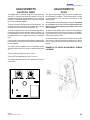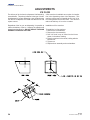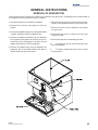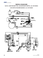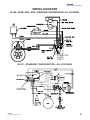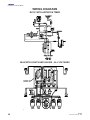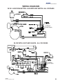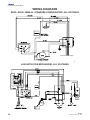
1
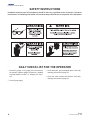
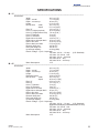
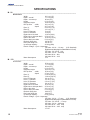
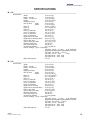
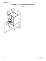
M & H SERIES M-15, 45, 90,150,200 & H-265 INSTALLATION & SERVICE GUIDE Part Number 5001192 Manitowoc Beverage Equipment 2100 Future Drive w Sellersburg, IN 47172-1868 Tel: 812.246.7000, 800.367.4233 Fax: 812.246.9922 www.manitowocbeverage.com In accordance with our policy of continuous product development and improvement, this information is subject to change at any time without notice. 5001192 Revision 27 January, 2003 Installation and Service Manual FOREWORD SerVend developed this manual as a reference guide for the owner/operator, service agent, and installer of this equipment. Please read this manual before installation or operation of the machine. Consult the troubleshooting guide within this manual for service assistance If you cannot correct the service problem, call your SerVend Service Agent or Distributor. Always have your model and serial number available when you call. Your Service Agent ____________________________________________________________ Service Agent Telephone Number _________________________________________________ Model Number _______________________________________________________________ Serial Number _______________________________________________________________ The model and serial numbers are located on the right side of the dispenser, just behind the drainpan. Installation Date ______________________________________________________________ Your Local SerVend Distributor ___________________________________________________ Distributor Telephone Number ___________________________________________________ A qualified service technician should perform installation and start-up of this equipment. UNPACKING AND INSPECTION Note: The Unit was thoroughly inspected before leaving the factory. Any damage or irregularities should be noted at the time of delivery (or not later than 15 days from the date of delivery.) WARRANTY INFORMATION Consult your local SerVend Distributor for terms and conditions of your warranty. Your warranty specifically excludes all beverage valve brixing, general adjustments, cleaning, accessories and related servicing. Your warranty card must be returned to SerVend to activate the warranty on this equipment. If a warranty card is not returned, the warranty period can begin when the equipment leaves the SerVend factory. No equipment may be returned to SerVend without a written Return Goods Authorization (RGA). Equipment returned without an RGA will be refused at SerVend’s dock and returned to the sender at the sender’s expense. Please contact your local SerVend distributor for return procedures. 5001192 Revision 03 February, 2003 3 Installation and Service Manual SAFETY INSTRUCTIONS Installation and start-up of this equipment should be done by a qualified service technician. Operation, maintenance, and cleaning information in this manual are provided for the user/operator of the equipment. DAILY CHECK LIST FOR THE OPERATOR • Check CO2 supply. If CO2 supply is low, an arrow on the primary regulator gauge will point to a shaded area that reads “Low CO2” or “Change CO2 Cylinder.” • Check Syrup supply. 4 • Clean drain pan, grid, and splash panel. See daily cleaning instructions on page 18. • Clean the valve nozzles and diffusers. See daily cleaning instructions on page 18. 5001192 Revision 03 February, 2003 Installation and Service Manual TABLE OF CONTENTS FOREWORD ........................................................................................................ UNPACKING AND INSPECTION ........................................................................ WARRANTY INFORMATION ............................................................................... SAFETY INSTRUCTIONS ................................................................................... DAILY CHECK LIST FOR THE OPERATOR ....................................................... COMPATIBLE ICE ............................................................................................... 3 3 3 4 4 7 ICE RECOMMENDED FOR DISPENSING ............................................................................ 7 EQUIPMENT OVERVIEW .................................................................................... 8 HOW THE ICE DISPENSER WORKS ................................................................................... 8 ICE STORAGE AND DISPENSING ....................................................................................... 8 EQUIPMENT SPECIFICATIONS ........................................................................................... 9 OVERALL M - SERIES DIMENSIONS .................................................................................. 9 SPECIFICATIONS .............................................................................................. 11 M - 15 .................................................................................................................................. 11 M - 45 .................................................................................................................................. 11 M - 90 .................................................................................................................................. 12 M - 150 ................................................................................................................................ 12 M - 200 ................................................................................................................................ 13 M - 250 ................................................................................................................................ 13 OVERALL H - SERIES DIMENSIONS.............................................................. 14 SPECIFICATIONS ............................................................................................. 15 H - 265 ................................................................................................................................. 15 INSTALLATION.................................................................................................. 16 COUNTER TOP INSTALLATION ......................................................................................... 16 FLOOR INSTALLATION ...................................................................................................... 17 ADDING AN ICE MACHINE TO A SERVEND DISPENSER ............................. 18 BEVERAGE SYSTEM ....................................................................................... 19 CLEANING AND SANITIZING ............................................................................................. 19 5001192 Revision 03 February, 2003 5 Installation and Service Manual TABLE OF CONTENTS TROUBLESHOOTING ....................................................................................... 20 CONDITION ........................................................................................................................ 20 INVESTIGATION: ................................................................................................................ 20 CHECK / HOW TO CHECK: ................................................................................................ 20 CORRECTION: ................................................................................................................... 20 CONDITION ........................................................................................................................ 21 INVESTIGATION ................................................................................................................. 21 CHECK / HOW TO CHECK ................................................................................................. 21 CORRECTION .................................................................................................................... 21 CONDITION ........................................................................................................................ 22 INVESTIGATION ................................................................................................................. 22 CHECK / HOW TO CHECK ................................................................................................. 22 CORRECTION .................................................................................................................... 22 ADJUSTMENTS ................................................................................................ 23 AGITATION TIMER .............................................................................................................. 23 DOOR ................................................................................................................................. 23 ICE FLOW ........................................................................................................................... 24 GENERAL INSTRUCTIONS .............................................................................. 25 REMOVAL OF GEAR MOTOR ............................................................................................ 25 WIRING DIAGRAMS ......................................................................................... 26 M-150 : H-265 PUSH BUTTON : H-265 WITH KEY SWITCH - ALL VOLTAGES .................. 26 H-265 WITH COIN MECHANISM - ALL VOLTAGES ............................................................ 26 WIRING DIAGRAMS ......................................................................................... 27 M-15A : M-15B : M-45 : M-90 : STANDARD CONFIGURATION - ALL VOLTAGES ............. 27 M-15C : STANDARD CONFIGURATION - ALL VOLTAGES ................................................ 27 M-15C WITH AGITATION TIMER......................................................................................... 28 M-90 WITH LIGHTS AND VALVES - ALL VOLTAGES ......................................................... 28 M-150 : H-265 PUSH BUTTON : H-265 WITH KEY SWITCH - ALL VOLTAGES .................. 29 M-150 WITH LIGHT AND VALVES - ALL VOLTAGES ......................................................... 29 WIRING DIAGRAMS ......................................................................................... 30 M-200 : M-250 : M250-36 : STANDARD CONFIGURATION - ALL VOLTAGES ................... 30 H-265 WITH COIN MECHANISM - ALL VOLTAGES ............................................................ 30 6 5001192 Revision 03 February, 2003 Installation and Service Manual COMPATIBLE ICE ICE RECOMMENDED FOR DISPENSING FULL CUBE 7/8" x 7/8" x 7/8" MINI CUBE 3/8" x 7/8" x 7/8" CUBELET 5/8" x 5/8" x 5/8" NEW EAGLE SERIES MINI CUBE 3/4" x 3/4" x 3/4" LENTICULAR 1 3/8" x 3/8" 75 0.3 1.125" 1.125" MINI 7/8" DIA x 3/4" LONG GOURMET-SMALL 1" DIA x 3/4" SerVend Dispensers are designed to dispense hard, cube ice up to two and one half cm (one inch) square. The ice shapes and sized listed are recommended for dispensing. 5001192 Revision 03 February, 2003 CONTOUR 3/8" x 1 1/4" x 1 1/4" CRESCENT CUBE “Super Cooled” bagged ice is not recommended for dispensing. “Super Cooled” ice is ice that has been stored in freezers at or below -17°C (0°F). Should it be necessary to use “Super Cooled” ice, allow the bag(s) to warm at room temperature for 25 to 30 minutes before placing the ice in the dispenser. 7 Installation and Service Manual EQUIPMENT OVERVIEW HOW THE ICE DISPENSER WORKS ICE STORAGE AND DISPENSING Ice is stored in the dispenser’s bin. Ice is transported from the bottom of the bin to the ice dispense point by the paddle wheel. The injection molded paddle wheel has paddles which lift the ice to the dispense point. SEQUENCE OF OPERATION: PUSH LEVER ICE DISPENSING The customer’s cup presses against the push plate. The push plate then raises a microswitch actuator arm on the right side of the dispensing chute. The microswitch actuator arm hits the lever of the microswitch. The energized microswitch activates the solenoid, which pulls down the solenoid plunger. The plunger is connected to a cable, which is then connected to a pulley. This raises the door of the ice chute. The energized microswitch also activates the gear motor. The gear motor turns the agitator and paddle wheel, lifting the ice from the bottom of the bin to the ice dispenser point. Ice falls forward through the open door, through the bin spout, through the ice chute and into the customer’s cup. 8 SEQUENCE OF OPERATION: PUSH BUTTON ICE DISPENSING Customer’s finger presses the push button, located in the merchandiser frame. The button is labeled “ICE” The push button energized the plunger microswitch. The energized microswitch activating the solenoid, which pulls down the solenoid plunger. The plunger is connected to a cable, which is then connected to a pulley. This raises the door on the ice chute. The energized microswitch also activates the gear motor. The gear motor turns the agitator and paddle wheel, lifting ice from the bottom of the bin to the ice dispense point. The dispenser paddle wheel turns counter clockwise looking at the wheel from the outside front of the dispenser. Ice falls forward through the open door, through the bin spout, into the ice chute and into the customer’s cup. 5001192 Revision 03 February, 2003 Installation and Service Manual HOW THE ICE DISPENSER WORKS (CONT’D) SEQUENCE OF OPERATION: KEY SWITCH OR COIN OPERATED ICE DISPENSING (H265) The key switch or coin mechanism engages a microswitch. The energized microswitch activates the solenoid, which pulls down the solenoid plunger. The plunger is connected to a cable, which is then connected to a pulley, this raises the door of the ice chute. The energized microswitch also activates the gear motor. The gear motor turns the agitator and paddle wheel, lifting ice from the bottom of the bin to the ice dispense point. Ice falls forward through the open door, through the bin spout, into the ice chute and into the customer’s container. EQUIPMENT SPECIFICATIONS OVERALL M - SERIES DIMENSIONS FRONT DIMENSIONS > < TOP DIMENSIONS 5001192 Revision 03 February, 2003 9 Installation and Service Manual OVERALL DIMENSIONS (CONT’D) M - SERIES < REAR DIMENSIONS BOTTOM DIMENSIONS > 10 5001192 Revision 03 February, 2003 Installation and Service Manual SPECIFICATIONS M - 15 ______________________________________________________________________ Dimensions: Width 38.1 cm (15”) Depth - overall 71.1 cm (28”) Depth - counter top 66 cm (26”) Height 81.3 cm (32”) Bin Top Size - width 38.1 cm (15”) - depth 52.1 cm (20.5”) Rear “A” 19.1 cm (7.5”) Hole “E” Height (top hole) 20.5 cm (8.06”) Hole “H” Height (bottom hole) 7.8 cm (3.06”) Hole “E” Diameter 5 cm (2”) Hole “H” Diameter 5 cm (2”) Right side to bin drain 19.0 cm (7.5”) Right side to drain pan drain 25.4 cm (10.0”) Rear to bin drain 35.9 cm (14.12”) Rear to drain pan drain 53.3 cm (21.0”) Bin drain fitting size 3/4” M.I.P.T. Drain pan fitting size 3/4” M.I.P.T. Ice storage capacity: 40.8 kg (90lb) Electric voltage - Cycle - Amperage: 120 Volts - 60 Hz. - 1.2 amp 100 Volts - 50 / 60 Hz. - N/A 220 Volts - 50 Hz. - 0.44 amp 220 Volts 60 Hz. - N/A 240 Volts 50 Hz. - 0.35 amp Motor Horsepower 1/15 (U.S. Standard) M - 45 ______________________________________________________________________ Dimensions: 5001192 Revision 03 February, 2003 Width 38.1 cm (15”) Depth - overall 71.1 cm (28”) Depth - counter top 66 cm (26”) Height 61.6 cm (32”) Dispense Height 24.8 cm (9.75”) Bin Top Size - width 38.1 cm (15”) - depth 45.4 cm (17.88”) Rear “A” 29.3 cm (11.5”) Rear “B” 19.1 cm (7.5”) Hole “F” Diameter 5 cm (2”) Hole “G” Diameter 5 cm (2”) Right side to bin drain 18.8 cm (7.5”) Right side to drain pan drain 25 cm (10”) Rear to bin drain 38.7 cm (15.25”) Rear to drain pan drain 47.6 cm (18.75”) Bin drain fitting size 3/4” M.I.P.T. Drain pan fitting size 3/4” M.I.P.T. Ice storage capacity: 20.4 kg (45lb) Electric voltage - Cycle - Amperage: 120 Volts - 60 Hz. - 1.2 amp (U.S. Standard) (Eight foot cord with plug is included with the U.S. unit) 100 Volts - 50 / 60 Hz. - N/A 220 Volts - 50 Hz. - 0.44 amp 220 Volts 60 Hz. - N/A 240 Volts 50 Hz. - 0.35 amp Motor Horsepower 1/15 11 Installation and Service Manual SPECIFICATIONS M - 90 ______________________________________________________________________ Dimensions: Width 38.1 cm (15”) Depth - overall 71.1 cm (28”) Depth - counter top 66 cm (26”) Height 81.3 cm (32”) Dispense Height 24.8 cm (9.75”) Bin Top Size - width 38.1 cm (15”) - depth 45.7 cm (18”) Rear “A” 29.2 cm (11.5”) Rear “B” 19.1 cm (7.5”) Hole “E” Diameter 5 cm (2”) Hole “H” Diameter 5 cm (2”) Right side to bin drain 16.8 cm (6.62) Right side to drain pan drain 25.4 cm (10”) Rear to bin drain 35.9 cm (14.12”) Rear to drain pan drain 53.3 cm (21”) Bin drain fitting size 3/4” M.I.P.T. Drain pan fitting size 3/4” M.I.P.T. Ice storage capacity: 40.8 kg (90lb) Electric voltage - Cycle - Amperage: 120 Volts - 60 Hz. - 1.2 amp (U.S. Standard) (Eight foot cord with plug is included with the U.S. unit) 100 Volts - 50 / 60 Hz. - N/A 220 Volts - 50 Hz. - 0.44 amp 220 Volts 60 Hz. - N/A 240 Volts 50 Hz. - 0.35 Motor Horsepower 1/15 M - 150 _____________________________________________________________________ Dimensions: Width 55.9 cm (22”) Depth - overall 71.1 cm (28”) Depth - counter top 66 cm (26”) Height 81.3 cm (32”) Dispense Height 29.2 cm (11.5”) Bin Top Size - width 55.9 cm (22”) - depth 47 cm (18.5”) Rear “A” 23.8 cm (9.375”) Rear “B” 14.9 cm (5.875”) Hole “E” Diameter 6.4 cm (2.5”) Hole “F” Diameter 3.5 cm (1.375”) Hole “G” Diameter 3.5 cm (1.375”) Hole “H” Diameter 6.4 cm (2.5”) Right side to bin drain 25.4 cm (10”) Right side to drain pan drain 35.6 cm (14”) Rear to bin drain 38.1 cm (15”) Rear to drain pan drain 53.3 cm (21”) Bin drain fitting size 3/4 M.I.P.T. Drain pan fitting size 3/4 M.I.P.T. Ice storage capacity: 68 kg (150 lb) Electric voltage - Cycle - Amperage: 120 Volts - 60 Hz. - 1.7 amp (U.S. Standard) (Eight foot cord with plug is included with the U.S. unit) 100 Volts - 50 / 60 Hz. - 1.7 amp 220 Volts - 50 Hz. - 0.85 amp 220 Volts 60 Hz. - 0.85 amp 240 Volts 50 Hz. - 0.85 amp Motor Horsepower: 1/7 H.P. 12 5001192 Revision 03 February, 2003 Installation and Service Manual SPECIFICATIONS M - 200 _____________________________________________________________________ Dimensions: Width 76.2 cm (30”) Depth - overall 76.2 cm (30”) Depth - counter top 72.4 cm (28.5”) Height 81.9 cm (32.25”) Dispense Height 30.5 cm (12”) Bin Top Size - width 76.2 cm (30”) - depth 57.2 cm (22.5”) Rear “A” 34 cm (13.375”) Rear “B” 25.1 cm (9.875”) Rear “C” 3.2 cm (1.25”) Hole “E” Diameter 6.4 cm (2.5”) Hole “F” Diameter 3.5 cm (1.375”) Hole “G” Diameter 3.5 cm (1.375”) Hole “H” Diameter 6.4 cm (2.5”) Right side to bin drain 38.1 cm (15”) Right side to drain pan drain 44.5 cm (17.5”) Rear to bin drain 37.5 cm (14.75”) Rear to drain pan drain 45.1 cm (17.75”) Bin drain fitting size 3/4” M.I.P.T. Drain pan fitting size 3/4” M.I.P.T. Ice storage capacity: 90.7 kg (200 lb) Electric voltage - Cycle - Amperage: 120 Volts - 60 Hz. - 1.7 amp (U.S. Standard) (Eight foot cord with plug is included with the U.S. unit) 100 Volts - 50 / 60 Hz. - 1.7 amp 220 Volts - 50 Hz. - 0.85 amp 220 Volts 60 Hz. - 0.85 amp 240 Volts 50 Hz. - 0.85 amp Motor Horsepower: 1/7 H.P. M - 250 _____________________________________________________________________ Dimensions: 5001192 Revision 03 February, 2003 Width 76.2 cm (30”) Depth - overall 76.2 cm (30”) Depth - counter top 72.4 cm (28.5”) Height 91.4 cm (36”) Dispense Height 30.5 cm (12”) Bin Top Size - width 76.2 cm (30”) - depth 50.2 cm (19.75”) Rear “A” 32.1 cm (12.625”) Rear “B” 25.1 cm (9.875”) Rear “C” 3.2 cm (1.25”) Hole “E” Diameter 6.4 cm (2.5”) Hole “F” Diameter 3.5 cm (1.375”) Hole “G” Diameter 3.5 cm (1.375”) Hole “H” Diameter 6.4 cm (2.5”) Right side to bin drain 35.6 cm (14”) Right side to drain pan drain 35.6 cm (14”) Rear to bin drain 36.8 cm (14.5”) Rear to drain pan drain 62.2 cm (24.5”) Bin drain fitting size 3/4” M.I.P.T. Drain pan fitting size 3/4” M.I.P.T. Ice storage capacity: 113.4 kg (250lb) Electric voltage - Cycle - Amperage: 120 Volts - 60 Hz. - 1.7 amp (U.S. Standard) (Eight foot cord with plug is included with the U.S. unit) 100 Volts - 50 / 60 Hz. - 1.7 amp 220 Volts - 50 Hz. - 0.85 amp 220 Volts 60 Hz. - 0.85 amp 240 Volts 50 Hz. - 0.85 amp Motor Horsepower: 1/7 H.P. 13 Installation and Service Manual OVERALL H - SERIES DIMENSIONS H - 265 30" 30 1/2" 22 1/2" IC E 61 1 PU SH 9" 25 7/16" 43 3/8" 14 5001192 Revision 03 February, 2003 Installation and Service Manual SPECIFICATIONS H - 265 _____________________________________________________________________ Dimensions: Width Depth - overall Depth - floor space Height- with 15 cm (6”) legs Dispense Height Bin Top Size - width - depth 76.2 cm (30”) 77.5 cm (30.5”) 72.4 cm (28.5”) 156.8 cm (61.75”) 22.9 cm (9”) 76.2 cm (30”) 57.2 cm (22.5”) Electrical entrance - Cord exits machine from the bottom Drain to floor 38.7 cm (15.25”) Drain to right side 38.1 cm (15”) Drain fitting size 3/4” F.I.P.T. Ice storage capacity: 113.4 kg (250lb) Electric voltage - Cycle - Amperage: 120 Volts - 60 Hz. - 1.7 amp (U.S. Standard) (Eight foot cord with plug is included with the U.S. unit) 100 Volts - 50 / 60 Hz. - 1.7 amp 220 Volts - 50 Hz. - 0.85 amp 220 Volts 60 Hz. - 0.85 amp 240 Volts 50 Hz. - 0.85 amp Motor Horsepower: 1/7 H.P. 5001192 Revision 03 February, 2003 15 Installation and Service Manual INSTALLATION COUNTER TOP INSTALLATION (M Series Dispenser) OPTION A: Check the equipment location. Assure the proper drain and electrical requirements are available before proceeding. Carefully remove the dispenser from the shipping carton. One drain tube fitting is with a 90° bend. This fitting attaches to the bin drain fitting. Underneath the dispenser toward the front of the dispenser is the bin drain. Attach the 90° fitting to the bin drain outlet. Slip the drain tubing over the tubing end of the fitting. Secure the tubing with the hose clamp provided. If the dispenser is to be set on legs, lay the dispenser on its’ back. Use the shipping cardboard as a protective interface between the dispenser and the floor. Thread the legs into the leg gussets on the bottom corners of the dispenser. If the dispenser is to be set on a counter without the legs, most local codes require the dispenser to have a silicone seal between the counter and the dispenser. Carefully pick up the dispenser, setting it in place. Be sure the dispenser is stable and level. Place a level on the top of the bin, side to side and front to back to see if the bin is level. If the dispenser has legs, level the dispenser bin by adjusting the dispenser legs. If the dispenser does not have legs, shim between the counter top and the dispenser. Remove the splash panel and drain pan from the front of the dispenser. If your dispenser has beverage valves attached, these valves will be attached to the splash panel. Included inside the dispenser from the factory is a length (1.8m [6ft.]) of vinyl tubing. One half of this tubing is to be used for the bin drain, with the other half of the tubing used for the drain pan drain. Attached to the tubing are two tubing adaptors. 16 The second drain tube fitting is a straight connector. This fitting attached to the drain pan fitting of the dispenser. Attach the fitting to the drain pan. Slip the drain tubing over the tubing end of the fitting. Secure the tubing with the hose clamp provided. Insulate all drain tubes. OPTION B: One drain tube fitting is with a straight connector. This fitting attaches to the bin drain fitting. Underneath the dispenser toward the front of the dispenser is the bin drain. Attach the straight fitting to the bin drain outlet. Slip the drain tubing over the tubing end of the fitting. Secure the tubing with the hose clamp provided. The second drain tube fitting is a 90° bend. This fitting attached to the drain pan fitting of the dispenser. Attach the fitting to the drain pan. Slip the drain tubing over the tubing end of the fitting. Secure the tubing with the hose clamp provided. Insulate all drain tubes. 5001192 Revision 03 February, 2003 Installation and Service Manual COUNTER TOP INSTALLATION FLOOR INSTALLATION If beverage valves are supplied with your dispenser, connect them to the beverage system at this time according to the information supplied by the beverage supplier. (H265 Series Dispenser) Route the electric wires under the dispenser and out to the electrical receptacle. Replace the drain pan to the dispenser. Secure the free ends of the vinyl drain tubing to the drain connections supplied by the owner/operator. Attach the splash panel to the front of the dispenser. Clean and sanitize the dispenser according to the directions in this manual. Check the equipment location. Assure the proper drain and electrical requirements are available before proceeding. Carefully remove the dispenser from the shipping carton. Lay the dispenser on its’ back. Use the shipping cardboard as a protective interface between the dispenser and the floor. Thread the legs into the leg gussets on the bottom corners of the dispenser. Carefully pick up the dispenser, setting it in place. Be sure the dispenser is stable and is level. Place a level on the top of the bin, side to side and front to back to see if the bin is level. Adjust the bin legs to level the dispenser. Drain 3/4" FPT Cord 5001192 Revision 03 February, 2003 17 Installation and Service Manual ADDING AN ICE MACHINE TO A SERVEND DISPENSER When mounting an ice machine on top of a SerVend dispenser place the front edge of the machine with the outside front edge of the dispenser bin. With some ice makers, there may be an overhang of the ice machine on the back of the dispenser. 6" MINIMUM Installations that include a SerVend ice machine on a SerVend dispenser, you must install an ice deflection baffle. Some installations may also require a manual fill lid, and possibly a strip lid kit. With a SerVend ice machine, the baffle will mount through the front panel of the ice machine. Refer to the drawing below. Several SerVend dispensers have a manual fill area in the front of the dispenser. This manual fill area is not covered by the ice machine. Order and obtain a manual fill lid from your local SerVend Distributor. Be sure to have the model and serial number of the dispenser available when ordering this or any part. OVERHANG SerVend manufactures dispensers in 22 inch, 30 inch, 36 inch, and 42 inch widths. At times a customer wishes to install a narrower ice machine than the width of the dispenser. In those instances, a strip lid kit is necessary to fill the excess bin opening of the dispenser. This strip lid kit must be ordered from your local SerVend distributor. You will need the model and serial number of your dispenser and the model of the SerVend ice machine to order the correct strip lid. Instructions for installation are included in each style of strip lid. ENCLOSURE LEFT SIDE PANEL FRONT CHANNEL ICE DEFLECTOR IC E COMPONENT BOX COVER SLOT BOTTOM SCREW FRONT PANEL 18 5001192 Revision 03 February, 2003 Installation and Service Manual BEVERAGE SYSTEM Installation and maintenance of the beverage system is not covered in this manual. The SerVend M series dispenser is an ice only dispenser. In some applications, The dispenser provides a mounting location for optional beverage valves. Please contact your SerVend Service Company for installation and maintenance of your beverage system. CLEANING AND SANITIZING 1. If a SerVend ice machine is mounted on top of the dispenser, remove the front panel of the ice maker. 2. Turn the ice maker off. 3. Empty all ice from the dispenser. 4. Unplug the dispenser from the electric receptacle. 5. Mix a cleaning solution consisting of a mild non abrasive detergent with water according to the package directions. 6. Using the cleaning solution and a soft bristle brush or cloth, wash the following dispenser parts: (With a top mounted ice maker, accessibility is through the front opening of the ice maker.) Paddle wheel pin (removed from the dispenser) Agitator (removed from the dispenser) Paddle wheel (removed from the dispenser) Entire bin area Ice chute Rear agitator bushing Drive shaft assembly inside bin 5001192 Revision 03 February, 2003 7. Mix a solution of 1.5 cl (1/2 oz.) household bleach to 7.5 L (2 gal) of clean water. To achieve 5.25% Cl Na O concentration per gallon of water, the mixture should supply 100 PPM (parts per million) of available chlorine. Or mix a solution of any NSF approved sanitizer, following the directions for mixing and applying that sanitizer. 8. Using the sanitizing solution and a soft bristle brush or cloth, clean each of the dispenser parts listed above. 9. Do not rinse the parts after they have been sanitized. Replace all parts back to the dispenser. 10. Pour in fresh clean ice into the dispenser bin. Or turn the ice maker back on. 11. Plug the dispenser into the receptacle. 12. Check for proper ice dispensing. 19 Installation and Service Manual TROUBLESHOOTING CONDITION INVESTIGATION: CHECK / HOW TO CHECK: CORRECTION: Dispenser does not dispense ice. There is no power to the dispenser. Is the dispenser plugged in? Plug the dispenser in. The dispenser is plugged in with power to the receptacle. With a meter, check to see if power is getting to the white and black cord wires inside the electric box. If no power is present, check the cord and plug of the dispenser. Replace if broken wire or connection is detected. Is power going through the microswitch? With the dispenser plugged in, meter probes on the “C” and “NC” terminals of the microswitch, energize the microswitch. If the meter starts out registering voltage, then does not register voltage when the switch is pushed, the switch is good. If no power is going through the microswitch, replace the switch or locate the broken connection. If the gear motor attempts to start but fails to do so, check the capacitor. To completely check the capacitor, you must use a capacitor checker according to the instructions supplied. If capacitor does not test correctly, replace the capacitor. There is power to the dispenser, however nothing runs. The gear motor runs but the dispensing paddle wheel does not turn. If gear motor fails to attempt to start, check the gear motor. To check the gear motor, disconnect power from the dispenser. Disconnect the gear motor wires in the junction box. Check for continuity through the gear motor. Remove the paddle wheel pin in the bin area. Is this pin broken or missing? 20 If gear motor does not test correctly, replace the gear motor. If the paddle wheel pin is broken or missing, replace the pin. 5001192 Revision 03 February, 2003 Installation and Service Manual TROUBLESHOOTING CORRECTION CONDITION INVESTIGATION CHECK / HOW TO CHECK Dispenser does not dispense ice. Gear motor runs but the dispensing paddle wheel does not turn. Remove the agitator and paddle wheel. Are you able to turn the shaft from the gear motor without turning the motor armature itself? Lower ice bin level. Is there at least one half bin of ice? Adjust door to minimum or larger opening. Dispenser runs but does not dispense ice. Is the ice in the bin of the proper size and type of ice? Dispenser runs, ice does not dispense but does congeal ice into a large ball. The agitation timer should be checked. See page 23 for proper check out procedure. If there is an ice maker mounted on top of the dispenser, is an ice deflection baffle installed? Adjust or replace timer if necessary. See page 23. Microswitch may be sticking. Check the microswitch and linkage to the microswitch. Clean linkage and microswitch. Replace microswitch if necessary. Check the agitation timer. Adjust the timer to two seconds on time and four hours off time. Also check timer for being shorted. Is excess water running into the dispenser from the top mounted ice maker? Dispenser crushes ice as it dispenses. Is the ice in the bin of the proper size and type of ice? Is there an ice maker on top of the dispenser? 5001192 Revision 03 February, 2003 Is the bin drain clean and open? See page 5 for acceptable ice. Is the ice being used a full size piece of ice? i.e. cubes full, not shallow, etc. If the dispenser has an ice maker on top, is there an ice deflection baffle installed between the dispenser and the ice maker? 21 Installation and Service Manual TROUBLESHOOTING CONDITION INVESTIGATION CHECK / HOW TO CHECK CORRECTION Dispenser crushes ice as it dispenses. Is there an ice maker on top of the dispenser? Is there at least 7.5 cm (3 in) between the top of the ice and the top of the dispenser bin? Ice continuous to dispense or dispenses by itself. Is the agitation timer (if equipped) set properly? Timer should agitate for two seconds every four hours. Remove the gear motor. Some models contain a shaft extension held on with a roll pin. If the roll pin is broken, replace. If the roll pin is good, replace the gear motor. Is the ice door opening fully when the dispenser operates? The ice door should open a minimum of 3.8 cm (1.5in). Does ice continue to dispense after the cup has been pulled away? Does the gear motor continue to run during this time? Does the ice dispense by itself without anyone around the dispenser? Does the dispenser do this at regular intervals? If not sufficient ice, add additional ice to bin. If the ice does not meet the dispensing parameters as described on page 5 replace the ice. Adjust or replace the agitation timer as required. The ice deflection baffle is to be installed between the dispenser and the ice maker. Install deflector if missing. Repair top mounted ice maker to reduce amount of water entering the dispenser. Clean the bin drain. Replace ice with acceptable type. Adjust ice machine to make a good, complete, not hollow piece of ice. Install deflector if missing. 22 5001192 Revision 03 February, 2003 Installation and Service Manual ADJUSTMENTS ADJUSTMENTS AGITATION TIMER DOOR The agitation timer is standard equipment for the dispensers with 90.7 kg. (200 lbs.) and larger bin storage. This timer is available as an option for all other dispensers. The purpose of the timer is to periodically agitate the ice in the bin, preventing the ice from congealing together. The door is used to stop the flow of ice to the container when the microswitch is released. The door assembly is not used to reduce the flow of ice. See the ice flow reducer on the following page. The timer is located in the electrical box of the dispenser. The two dials on the timer should be set to agitate the ice for two seconds every four hours of non ice dispenser use. To check the agitation timer, turn the off time dial (right dial on the drawing below) counter clockwise until the dial stops. Do not use the dispenser for 15 minutes. Within that time period, the agitator will turn. If the agitator does not turn, replace the timer. When operated, the door should open completely. This would be a minimum of 3.8 cm (1.5 in) as measured from the bottom of the chute opening to the bottom of the door when energized. To adjust the door opening, raise or lower the door solenoid in the opposite direction you wish to effect the door. EXAMPLE: If you wish to open the door wider, lower the door solenoid. This will raise the door wider. If the solenoid is electrically activated when the agitation timer moves the gear motor, the timer has shorted out internally and must be replaced. To move the solenoid, loosen the four machine screws on the side of the coil. Slide the solenoid in the direction you wish to move it. Tighten the screws on the solenoid to secure the coil in place. To correctly reset the agitation timer, turn both dials counter clockwise until they stop. Your “points” on the dials will be set at “0”. EXAMPLE OF DOOR ADJUSTMENT SCREW LOCATION Turn the ON time (left dial) from the “0” to the “2”. Turn the OFF time (right dial) from the “0” to the “4”. The drawing shows the position of the dials when the timer is set correctly. 5001192 Revision 03 February, 2003 23 Installation and Service Manual ADJUSTMENTS ICE FLOW The delivery of the ice from the dispenser is influenced by several factors. The primary influence is the type of ice being dispensed. If you are dispensing a wet, rounded corner ice, this ice will dispense at a faster rate than an ice with square corners. A flow restrictor is available as an option for installation in the dispensing chute of the dispenser. This restrictor will prevent a full paddle wheel “cup” of ice from being delivered into the chute. This will then reduce the delivery of ice to the container. Regardless of the ice you are dispensing, it is possible to reduce the delivery of the ice. However the reduction will depend upon the type of ice. DO NOT REDUCE THE DOOR OPENING TO REDUCE ICE FLOW. Installation of flow restrictor 24 To install the ice flow restrictor: 1. Remove the merchandiser. 2. Remove the door assembly. 3. Drill 3/16” hole in top of chute from the bin as shown in the above drawing. 4. Place the restrictor in the chute, holding with the bolt and nut. 5. Tighten nut. 6. Replace door assembly and merchandiser. 5001192 Revision 03 February, 2003 Installation and Service Manual GENERAL INSTRUCTIONS REMOVAL OF GEAR MOTOR These instructions are provided as a guide for the removal of the gear motor. Depending on the model number of your dispenser, these instructions may vary slightly. 1. Disconnect power from the electric receptacle. 2. Remove all ice from the ice storage bin of the dispenser. 3. Remove the paddle wheel pin from the paddle wheel / agitator assembly inside the dispenser bin. 4. Remove the agitator assembly from the dispenser bin by pushing the agitator to the back of the bin. Angle the front of the agitator to the side. Pull the agitator forward then out of the dispenser. 5. Remove the paddle wheel from the dispenser by pulling the hub of the paddle wheel to the back of the bin and off the gear motor shaft. 5001192 Revision 03 February, 2003 6. Remove the four bolts from the front wall of the dispenser. These bolts mount into the gear motor case. 7. Remove the front from the dispenser and expose the gear motor. 8. Disconnect the electric connector from the gear motor wire leads. 9. Remove the strap from around the gear motor. 10. You should be able to remove the gear motor from the dispenser. 11. To install a replacement gear motor, reverse this procedure. 25 Installation and Service Manual WIRING DIAGRAMS M-150 : H-265 PUSH BUTTON : H-265 WITH KEY SWITCH - ALL VOLTAGES H-265 WITH COIN MECHANISM - ALL VOLTAGES To Electric Power Supply 26 5001192 Revision 03 February, 2003 Installation and Service Manual WIRING DIAGRAMS M-15A : M-15B : M-45 : M-90 : STANDARD CONFIGURATION - ALL VOLTAGES TO ELECTRIC POWER SUPPLY M-15C : STANDARD CONFIGURATION - ALL VOLTAGES TO ELECTRIC POWER SUPPLY 5001192 Revision 03 February, 2003 27 Installation and Service Manual WIRING DIAGRAMS M-15C WITH AGITATION TIMER M-90 WITH LIGHTS AND VALVES - ALL VOLTAGES 28 5001192 Revision 03 February, 2003 Installation and Service Manual WIRING DIAGRAMS M-150 : H-265 PUSH BUTTON : H-265 WITH KEY SWITCH - ALL VOLTAGES To Electric Power Supply M-150 WITH LIGHT AND VALVES - ALL VOLTAGES To Electric Power Supply 5001192 Revision 03 February, 2003 29 Installation and Service Manual WIRING DIAGRAMS M-200 : M-250 : M250-36 : STANDARD CONFIGURATION - ALL VOLTAGES To Electric Power Supply H-265 WITH COIN MECHANISM - ALL VOLTAGES 30 5001192 Revision 03 February, 2003 Manitowoc Beverage Equipment 2100 Future Drive w Sellersburg, IN 47172-1868 Tel: 812.246.7000, 800.367.4233 Fax: 812.246.9922 www.manitowocbeverage.com In accordance with our policy of continuous product development and improvement, this information is subject to change at any time without notice. 5001192 Revision 03 February, 2003