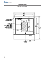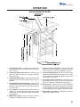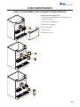
1
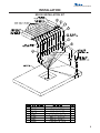
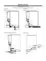
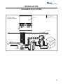
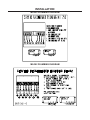
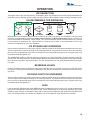
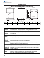
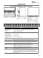
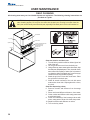
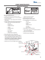
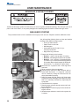
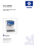
MII SERIES MII-250/302 Beverage/Ice Dispenser with Flex Manifold INSTALLATION & SERVICE GUIDE PARTNUMBER 5031216 Manitowoc Beverage Equipment 2100 Future Drive Sellersburg, IN 47172-1868 Tel: 812.246.7000, 800.367.4233 Fax: 812.246.9922 www.manitowocbeverage.com In accordance with our policy of continuous product development and improvement, this information is subject to change at any time without notice. October 17, 2006 REV3 FOREWORD Manitowoc Beverage Equipment (MBE) developed this manual as a reference guide for the owner/ operator, service agent, and installer of this equipment. Please read this manual before installation or operation of the machine. A qualified service technician should perform installation and startup of this equipment, consult the Troubleshooting Guide within this manual for service assistance. If you cannot correct the service problem, call your MBE Service Agent or Distributor. Always have your model and serial number available when you call. Your Service Agent ___________________________________________________________________ Service Agent Telephone Number ______________________________________________________ Your Local MBE Distributor ___________________________________________________________ Distributor Telephone Number _________________________________________________________ Model Number ______________________________________________________________________ Serial Number _______________________________________________________________________ Installation Date _____________________________________________________________________ UNPACKING AND INSPECTION Note: The dispenser was thoroughly inspected before leaving the factory. Any damage or irregularities should be noted at the time of delivery. WARRANTY INFORMATION Consult your local MBE Distributor for terms and conditions of your warranty. Your warranty specifically excludes all beverage valve brixing, general adjustments, cleaning, accessories and related servicing. Your warranty card must be returned to Manitowoc Beverage Equipment to activate the warranty on this equipment. If a warranty card is not returned, the warranty period can begin when the equipment leaves the MBE factory. No equipment may be returned to Manitowoc Beverage Equipment without a written Return Materials Authorization (RMA). Equipment returned without an RMA will be refused at MBE’s dock and returned to the sender at the sender’s expense. Please contact your local MBE distributor for return procedures. TABLE OF CONTENTS FOREWORD ........................................................................................................ 3 UNPACKING AND INSPECTION ......................................................................... 3 WARRANTY INFORMATION ............................................................................... 3 SAFETY ............................................................................................................... 6 IMPORTANT SAFETY INSTRUCTIONS ........................................................................... 6 CARBON DIOXIDE WARNING ......................................................................................... 6 QUALIFIED SERVICE PERSONNEL ................................................................................ 6 SHIPPING, STORAGE, AND RELOCATION ..................................................................... 6 ADDITIONAL WARNINGS ................................................................................................ 6 GROUNDING IN STRUCTIONS ........................................................................................ 7 INSTALLATION .................................................................................................... 8 PRE-INSTALLATION CHECK LIST .................................................................................. 8 UNIT INSTALLATION ....................................................................................................... 8 MII-250 INSTALLATION KIT ............................................................................................. 9 MII-302 INSTALLATION KIT ........................................................................................... 10 WATER & SYRUP LINES ................................................................................................ 11 DRAINAGE OPTIONS .................................................................................................... 12 BAG-IN-BOX (B-I-B) SYSTEM ....................................................................................... 13 TOP MOUNTED ICEMAKER REQUIREMENTS ............................................................. 14 ICE FLOW RESTRICTOR ............................................................................................... 14 ROCKING CHUTE ICE DELIVERY SWITCH ADJUSTMENT .......................................... 15 BAFFLE FOR MANITOWOC™ CUBERS ....................................................................... 16 BAFFLE FOR "Q" SERIES ICE MACHINES .................................................................. 16 MANUAL FILL LID FOR DISPENSERS WITH A CUBER ............................................... 16 GENERAL INSTRUCTIONS FOR REMOVAL OF GEAR MOTOR .................................. 17 MII-250 PLUMBING DIAGRAM ...................................................................................... 18 MII-302 PLUMBING DIAGRAM ...................................................................................... 18 OPERATION ...................................................................................................... 19 UNIT INSPECTION ......................................................................................................... 19 ICE RECOMENDED FOR DISPENSING ......................................................................... 19 ICE STORAGE AND DISPENSING ................................................................................. 19 BEVERAGE VALVES ..................................................................................................... 19 ROCKING CHUTE ICE DISPENSING ............................................................................. 19 LEGS .............................................................................................................................. 19 MII-250 MEASUREMENTS & SPECIFICATIONS ............................................................ 20 MII-302 MEASUREMENTS & SPECIFICATIONS ............................................................ 21 MII-250 FOOTPRINT ....................................................................................................... 22 MII-302 FOOTPRINT ....................................................................................................... 23 Installation and Service Manual TABLE OF CONTENTS CARBONATION ............................................................................................................. 24 SYRUP DELIVERY SYSTEM .......................................................................................... 24 RACKING ....................................................................................................................... 24 B-I-B ............................................................................................................................... 24 PUMPS ........................................................................................................................... 24 AUTO BAG SELECTORS ............................................................................................... 24 BACK ROOM PACKAGE ............................................................................................... 25 115V/220V NON ADJUSTABLE AGITATION TIMER ...................................................... 26 USER MAINTENANCE ...................................................................................... 27 PREVENTATIVE MAINTENANCE .................................................................................. 27 HOW TO DISASSEMBLE FOR CLEANING OR MAINTENANCE .................................. 27 DAILY CLEANING .......................................................................................................... 30 MONTHLY CLEANING ................................................................................................... 31 BEVERAGE SYSTEM CLEANING ................................................................................. 32 BAG-IN-BOX SYSTEM ................................................................................................... 32 EXPLODED VIEWS, PARTS & DIAGRAMS ..................................................... 34 MII-250 EXPLODED VIEW WITH 8 VALVE FLEX MANIFOLD ........................................ 34 MII-250 PARTS LIST ...................................................................................................... 35 MII-302 EXPLODED VIEW WITH TWO 6 VALVE FLEX MANIFOLDS ............................ 36 MII-302 PARTS LIST ...................................................................................................... 37 MII-302 CARB WATER TUBING ..................................................................................... 38 STRIP LID ASSEMBLY (5030332) .................................................................................. 39 MII-250 115V WIRING DIAGRAM ................................................................................... 39 MII-302 115V WIRING DIAGRAM ................................................................................... 40 TROUBLESHOOTING ....................................................................................... 41 INDEX................................................................................................................. 47 5 SAFETY IMPORTANT SAFETY INSTRUCTIONS Carefully read all safety messages in this manual. Learn how to operate the MII unit properly. Do not allow anyone to operate the unit without proper training and keep it in proper working condition. Unauthorized modifications to the MII may impair function and/or safety and affect the life of the unit. CARBON DIOXIDE WARNING DANGER: Carbon Dioxide (CO2) displaces oxygen. Exposure to a high concentration of CO2 gas causes tremors, which are followed rapidly by loss of consciousness and suffocation. If a CO2 gas leak is suspected, particularly in a small area, immediately ventilate the area before repairing the leak. CO2 lines and pumps should not be installed in an enclosed space. An enclosed space can be a cooler or small room or closet. This may include convenience stores with glass door self serve coolers. If you suspect CO2 may build up in an area, venting of the B-I-B pumps and / or CO2 monitors should be utilized. QUALIFIED SERVICE PERSONNEL WARNING: Only trained and certified electrical and plumbing technicians should service this unit. All wiring and plumbing must conform to national and local codes. SHIPPING, STORAGE, AND RELOCATION CAUTION: Before shipping, storing, or relocating this unit, syrup systems must be sanitized. After sanitizing, all liquids (sanitizing solution and water) must be purged from the unit. A freezing environment causes residual sanitizing solution or water remaining inside the unit to freeze, resulting in damage to internal components. ADDITIONAL WARNINGS Installation and start-up of this equipment should be done by a qualified service technician. Operation, maintenance, and cleaning information in this manual are provided for the user/operator of the equipment. Save these instructions. Installation and Service Manual SAFETY GROUNDING IN STRUCTIONS WARNING: Risk of electrical shock. Connect to a properly grounded outlet only. This appliance must be grounded. In the event of malfunction or breakdown, grounding provides a path of least resistance for electric current to reduce the risk of electric shock. This appliance is equipped with a cord having an equipment-grounding conductor and a grounding plug. The plug must be plugged into an appropriate outlet that is properly installed and grounded in accordance with all local codes and ordinances. DANGER – Improper connection of the equipment-grounding conductor can result in a risk of electric shock. The conductor with insulation having an outer surface that is green with or without yellow stripes is the equipment grounding conductor. If repair or replacement of the cord or plug is necessary, do not connect the equipment-grounding conductor to a live terminal. Check with a qualified electrician or serviceman if the grounding instructions are not completely understood, or if in doubt as to whether the appliance is properly grounded. Do not modify the plug provided with the appliance – if it will not fit the outlet, have a proper outlet installed by a qualified electrician. WARNING – When using electric appliances, basic precautions should always be followed, including the following: a) Read all the instructions before using the appliance. b) To reduce he risk of injury, close supervision is necessary when an appliance is used near children. c) Do not contact moving parts. d) Only use attachments recommended or sold by the manufacturer. e) Do not use outdoors. f) For a cord-connected appliance, the following shall be included: • Do not unplug by pulling on cord. To unplug, grasp the plug, not the cord. • Unplug from outlet when not in use and before servicing or cleaning. • Do not operate any appliance with a damaged cord or plug, or after the appliance malfunctions or is dropped or damaged in any manner. Return appliance to the nearest authorized service facility for examination, repair, or electrical or mechanical adjustment. g) For a permanently connected appliance – Turn the power switch to the off position when the appliance is not in use and before servicing or cleaning. h) For an appliance with a replaceable lamp – always unplug before replacing the lamp. Replace the bulb with the same type. i) For a grounded appliance – Connect to a properly grounded outlet only. See Grounding Instructions. SAVE THESE INSTRUCTIONS 7 INSTALLATION PRE-INSTALLATION CHECK LIST When installing any system, first make sure the major components are available. Generally the major components necessary for an installation are: Bulk Syrup System also: B-I-B System also: Syrup connectors for Bulk tank B-I-B connectors Gas connectors for Bulk tank B-I-B regulator set Bulk syrup tanks B-I-B rack Double Check: B-I-B syrup boxes Do you have enough space to install the disPost Mix System: penser or a dispenser and top mounted cuber? CO2 regulator set Does the top mounted cuber (if utilized) have a Beverage dispenser minimum of 6 inches (15.3) cm) clearance on all sides? Beverage tubing CO2 tank Is the countertop level? Carbonator Can the countertop support the weight of the dispenser, or the dispenser/cuber combination plus the weight of the stored ice? Stepless (Oetiker) clamps Chain for CO2 tank Also consider the location of the following items before installation: • Water line • Power outlet • Drain • Heating and air conditioning ducts UNIT INSTALLATION 1. Place the dispenser in the desired location. 2. Run the beverage lines and water lines (make sure to install the water connections to the proper inlets). (Refer to plumbing diagrams) 3. Install drain plumbing and insulate. (See Drainage Options) 4. 5. 6. 7. 10. Set flexible manifold for correct drink settings. Fill bin with ice. Connect power supply. Brix beverage valves. Meet all code requirements. Installation and Service Manual INSTALLATION MII-250 INSTALLATION KIT 9 INSTALLATION MII-302 INSTALLATION KIT Installation and Service Manual INSTALLATION WATER & SYRUP LINES This kit facilitates connecting the unit to a 12-16 line conduit, with one or two carbonated water recirculating systems, and one or two plain water supply lines, and maximum 8 syrup product lines. The Unit is shipped with connecting lines terminating under the unit. It will be necessary to make a 90° turn down through the counter top, to connect to the conduit. It will also be necessary to fully insulate this new added section before passing through the counter top, or before hooking to main conduit. CARB WATER LINES: SYRUP LINES: • Unit has two (2) carb water lines, one for each flex manifold. • Use 2 @ ½” x ½” elbow and 6-12" of ½” conduit tubing to make connection bend from unit down through hole in counter top, to mate with conduit. • Conduit with only two (2) circulating carb water lines • Use 2 @ ½” barb U-Bend adaptors (invert one) to connect the two carb circulating lines from conduit to the two carb water lines from the unit. Use short ½” conduit line to connect the two U-bends as shown (option to 8). • Conduit with four (4), two sets of recirculating carb water lines • Use 2 @ ½” barb U-Bend adaptors, to connect each set of circulating conduit lines to each carb water line from unit as shown (8) . • Unit has eight (8) syrup lines • Use 7 @ ¼ x 3/8" and 1 @ ¼ x ½” elbows and proper size conduit tubing to make connection bend from unit down through hole in counter top, to mate with conduit. • FULLY INSULATE (no air gaps) and finish with tape wrap, all these connections from unit, through 90° bend connection and down close to straight conduit connection. Locate Unit properly on counter, and secure to counter as shown in Unit Installation Instructions. Finish connections to Conduit with 3/8" x 3.8" and ½” x ½” straight barb connectors, and Ubend adapters, as needed. • FULLY INSULATE and finish with tape wrap, all these connections to the conduit. PLAIN WATER LINES: • Unit has two (2) plain water lines, one for each flex manifold. • Use 2 @ 3/8" x 1/2" elbows and 6-12" of 1/2" conduit tubing to make connection bend from unit down through hole in counter top, to mate with conduit. • Conduit with only one (1) plain water line • Use 1 @ ½” U-bend adaptor, to connect the two plain water lines to one plain water line from conduit (option to 3.) • Conduit has two (2) plain water lines • Use 2 @ ½” straight adaptors to connect each plain water line from unit to each plain water line from conduit as shown (3.) 11 INSTALLATION DRAINAGE OPTIONS The drains for MII Series connects to the drain pan. Option One Option Two Drainage through the bottom of the unit: Drainage through the back of the unit: Radiator clamp 90 elbow fitting Straight fitting Radiator clamp Flexible tubing Radiator clamp Flexible tubing Drain with Extended Splash Panel Rear of Unit Holes for beverage lines Holes for drain pan drain Installation and Service Manual INSTALLATION BAG-IN-BOX (B-I-B) SYSTEM NOTE: MII with Valves System Overview This is a simplified schematic to show the basic operation of the beverage system. Dispenser 5 Countertop SYRUP SYRUP SYRUP CARBONATED WATER CARBONATED WATER NON-CARBONATED WATER BIB Syrup Pump SYRUP 1800 Tap Water ox n-B g-I p a B yru S on rt Ca 90 60 1 Tap Water 3 Multiplex CO2 CO2 Cylinder 2 SYRUP CO2 CO2 SYRUP Drawing #: 5010102-0 13 INSTALLATION TOP MOUNTED ICEMAKER REQUIREMENTS 1 Location - Avoid placing the dispenser and/or ice machine near heat sources such as radiators, ovens, refrigeration equipment and direct sunlight. 2 Clearances - Six inch (15.2 cm) clearance on all sides of the icemaker is needed. 3 Front of icemaker to be flush with front of dispenser- The front of the icemaker should be flush with the front of the dispenser, as shown in the drawing above. Because the icemaker is flush with the 1 front of the dispenser, some icemakers may overhang at the back of the dispenser. 4 Drains - A separate drain line is required for the ice machine, in addition to a drain line for the ice/beverage dispenser. 5 MII Series dispensers require an adapter kit to install some top-mounted icemakers. Contact your local Multiplex distributor for the correct adapter kit. 6" (15.2 cm) clearance for cuber 2 6" (15.2 cm) 6" (15.2 cm) cuber 6" (15.2 cm) 5 6" (15.2 cm) 3 3 4 4 NOTE: For full information about icemaker installation, including plumbing lines connections and electrical requirements, see the icemaker installation manual. ICE FLOW RESTRICTOR For all MII, MD and MDH Series dispensers an Ice flow restrictor is available. This ice flow restrictor decreases the amount of ice allowed to enter the ice chute by blocking a small area at the entrance of the dispenser chute. This in turn restricts the flow of ice that is dispensed in to your cup. Ice Flow Restrictor Please refer to the instructions included in kit #5013822 for more information on how to install. Installation and Service Manual INSTALLATION ROCKING CHUTE ICE DELIVERY SWITCH ADJUSTMENT 1 To properly adjust the switch, first unplug the power cord to the unit then remove the merchandiser. This will give you access to the ice delivery switch located on the left side of the rocking chute. 2 Begin by observing the chute by slowly pushing against the rocking chute. When the ice delivery switch clicks, measure the distance from the door stops on the rocking chute bracket to the door. The distance between the two should be no more than 1/4", but no less than 1/16". 3 The left side of the rocking chute has a tab that pushes up on the ice delivery switch. To adjust it, use needle nose pliers and bend the arm of the switch up or down in order to change the point where the tab makes contact with the switch arm. 15 INSTALLATION BAFFLE FOR MANITOWOC™ CUBERS When installing a Manitowoc™ “S” series Ice Machine on a MII dispenser, a baffle kit is required for proper installation. The baffle kit is designed to prevent ice from lying against the front of the ice machine, and melting down the front of the dispenser. There are two different baffle kits available, one kit is for the 30" wide “S” series ice machine, and the other kit is for the 22" wide “S” series ice machine. These two Kits are available through your local Manitowoc Distributor. List prices may be subject to change without notification. Please call your local parts distributor for current pricing before ordering. Ice Maker Baffle Installation: 1. Remove both front panels. 2. Examine the ice machine to see if the machine has four screws on the lower front plastic panels. 3. If there are screws, remove them from the countersunk holes on the front surface of the machine, save the screws. 4. Install the deflector, using the four screws removed in step three. 5. Four screws and two backing plates are in the kit. 6. If there are no screws on the ice machine (step 2), pierce the thin plastic countersunk holes, install the backing plates and install the deflector using the screws from the kit. 7. Replace the front panels. Part Number Description 5029518 ........................ Baffle Kit 30” 5029517 ........................ Baffle Kit 22” BAFFLE FOR "Q" SERIES ICE MACHINES 1. Position baffle on top of water well with tab on the front and the other tab inside the water well. 2. Mount the baffle on the left side of the ice maker using the hole and screw provided. MANUAL FILL LID FOR DISPENSERS WITH A CUBER If you are top mounting your MII Series dispenser with a cuber, you will require a lid for the manual fill area at the top, front of the dispenser. If you ordered a dispenser and a cuber at the same time, the manual fill lid was included with the unit. The manual fill lid can be ordered from your local Multiplex distributor. Installation and Service Manual INSTALLATION GENERAL INSTRUCTIONS FOR REMOVAL OF GEAR MOTOR These instructions are provided as a guide for the removal of the gear motor. Depending on the model number of your dispenser, these instructions may vary slightly. 1. Disconnect power from the electric receptacle. 2. Remove all ice from the ice storage bin of the dispenser. 3. Remove the paddle wheel pin from the paddle wheel / agitator assembly inside the dispenser bin. 4. Remove the agitator assembly from the dispenser bin by pushing the agitator to the back of the bin. Angle the front of the agitator to the side. Pull the agitator forward then out of the dispenser. 5. Remove the paddle wheel from the dispenser by pulling the hub of the paddle wheel to the back of the bin and off the gear motor shaft. 6. Remove the splash panel from the dispenser and expose the gear motor. 7. Disconnect the electric connector from the gear motor wire leads. 8. Remove the pin in front of the gear motor. 9. You should be able to remove the gear motor from the dispenser. 10. To install a replacement gear motor, reverse this procedure. Removable front merchandiser panel Agitator Ice bin Beverage valve (option) Ice Water line Paddle wheel Gear motor Drain pan Rocking chute ice dispense chute 17 INSTALLATION MII-250 PLUMBING DIAGRAM MII-302 PLUMBING DIAGRAM Installation and Service Manual OPERATION UNIT INSPECTION Thoroughly inspect the unit upon delivery. Immediately report any damage that occurred during transportation to the delivery carrier. Request a written inspection report from a claims inspector to document any necessary claim. ICE RECOMENDED FOR DISPENSING MII dispensers are designed to dispense hard, cube ice up to one-inch square. The ice shapes and sizes listed above are recommended for dispensing. Warm “Super Cooled” Ice Before Dispensing “Super Cooled” ice is not recommended for dispensing. “Super cooled” ice is ice that has been stored in freezers below 32oF. Should it be necessary to temporarily use “super cooled” ice, allow the ice to warm at room temperature for 25 to 30 minutes before placing the ice in the dispenser. ICE STORAGE AND DISPENSING As the customer presses the rocking chute, the arm at the top left rear of the chute pushes upward on the door lock. The door opens until it contacts the stops in the mounting brackets. The plastic arm on the ice chute also activates the lever of the ice dispensing switch. When activated, the micro switch starts the gear motor. The gear motor turns the paddle wheel and agitator arm. The paddlewheel carries ice. Periodic agitation is optional on the MII-150 and MII-175 and is standard on the MII200, MII-250, MII-302 and MII-402. During periodic agitation, the paddle wheel and agitator turn for approximately three seconds every three and one half-hours. The door lock prevents ice from being dispensed during the agitation cycle. BEVERAGE VALVES Post-mix beverage valves are designed to precisely meter the flow of both water and syrup to obtain the proper mixing ratio. The syrup and soda water components of the post-mix beverage are mixed as they leave the beverage valve. ROCKING CHUTE ICE DISPENSING As the customer presses the rocking chute, the arm at the top left rear of the chute pushes upward on the door lock. The door opens until it contacts the stops in the mounting brackets. The plastic arm on the ice chute also activates the lever of the ice dispensing switch. When activated, the micro switch starts the gear motor. The gear motor turns the paddle wheel and agitator bar. LEGS Legs are optional equipment with most MBE dispensers. Standard legs are four-inch (10.2 cm) tall stainless steel legs. MII 302 and MII 402 cannot be placed on legs. When installing legs on a MII Series dispenser, leg braces should be used. These are metal braces fitting side to side under the dispenser that reinforce the leg attachment area. It is recommended if an icemaker is installed on top of the dispenser, legs should not be installed. 19 Installation and Service Manual OPERATION MII-250 MEASUREMENTS & SPECIFICATIONS FRONT VIEW BOTTOM VIEW BACK VIEW H K A L M B 3/8"-16 Thread Mounting Holes for optional legs P N C E D F G Unit A B C D E F MII -250 39 " 12.5" 30 " 1.5 " 9.938" 13.5" G H K L 20 " 30.5" 28.375" 22.5" M N 21.688 " 1.75" P 28.438" MII-250 Standard Features Lighted Merchandiser, "ice" graphics, key switch, stainless steel legs, drain kit, Lighted Merchandiser, "ice" graphics, key switch, stainless steel legs, drain kit, Dimensions 30" W x 30.5" D x 39"H (add 1.25 to height for lid) Shipping Weights 199 lbs./90.5 kgs Countertop Weights 175 lbs./79.5 kgs Ice Storage Capacity up to 250 lbs./ 114 kgs.of ice. Electrical Requirements Dispenses: 120V/60Hz/2.8 FLA Dispenses: 120V/60Hz/2.8 FLA Drain Two 3/4" (1.96cm) PVC (N.P.T.) drain fittings, (one pre-installed 3/4" (1.96cm) PVC fitting extends from drain pan. A second fitting extends from bin.) Machine Compatibility Manual fill or top-mount with compatible 22" and 30" wide ice machines. Contact factory for baffle and ice wide ice machines. Contact factory for baffle and ice Graphic Area Dimensions Physical trim: 29.5"W x 16.625"H 74.93W x 42.228H (cm) Visual area: 28.5"W x 15.625"H 72.39W x 39.688H (cm) Service Motor, drain and electrical connections are front serviceable. Options Wilshire FFV standard beverage valves (other valves also available), extended splash panel, splash guards, adapter kits for top-mounted ice machine applications. 20 Installation and Service Manual OPERATION MII-302 MEASUREMENTS & SPECIFICATIONS A D L C F K E M G H J N O P Q Unit A B C D E F G H J K L M N O P Q MII -302 33.25" 12.50" 42.75" 1.38" 5.59" 9.10" 12.16" 31.00" 15.78" 28.78" 22.50" .82" 26.97" 30.47" 33.75" 37.16" MII-302 Standard Features Key Switch, Drain Kits, 12" high lighted merchandiser and timed agitation Dimensions 42.75" W x 31" D x 34.25" H (inches) 108.6 W x 78.74 D x 87 H (cm) Shipping Weights 470 lbs. / 213 kgs. Countertop Weights 402 lbs. / 182 kgs. Ice Storage Capacity 300 lbs. / 136 kgs. Electrical Requirements Dispenser: 120V/60Hz/3.5FLA Drain Two pre-installed 3/4" (1.9 cm) PVC (N.P.T.) drain fittings extends from drain pan. Ice bin drains directly into drain pan for front clean out, no hook up necessary. Machine Compatibility Manual fill or top-mount with compatible 30" wide ice machine. Certain top-mounted machines may reduce storage capacity. Contact distributor or MBS for baffle and ice maker lid requirements for top-mounted ice machine applications. Graphic Area Dimensions Standard Physical trim - 42.625" W x 11" H (108.2 W x 27.94 H (cm)) Visual area - 41.75" W x 10.062" H; (106 W x 25.56 H (cm)) Extended Merchandiser:Physical trim - 42.5" W x 23.813" H (107.95 W x 60.49 H (cm)) Visual area - 41.624" W x 22.875" H (105.72 W x 58.1 H (cm)) Service Motor, drain and electrical connections are front serviceable. Options The MII-302 will accommodate up to 12 Flomatic 464 (at 3-4 oz/sec) beverage valves. F-464 valves are available in sanitary lever, push button, Autofill lever and portion control. Other valves available, contact factory for details. Leg kits not available for MDH-302. Other options: regulators, carbonator, side water lever installation kits and side splash panels. 21 Installation and Service Manual OPERATION MII-250 FOOTPRINT 22 Installation and Service Manual OPERATION MII-302 FOOTPRINT 23 Installation and Service Manual OPERATION CARBONATION The purpose of the carbonator is to take regular tap water at street water pressure (minimum 20 PSI dynamic or flowing pressure) 1/2” water line and increase the water to beverage system pressure (usually 100 PSI). This water is then combined with the CO2 gas. Because the water and gas are at the same pressure, the CO2 will dissolve into the water. Chilling the mixture before dispensing will assist in locking the carbon dioxide into the water. After dispensing, the CO2 may be unlocked from the liquid. The CO2 will gradually leave the liquid due to pressure and temperature changes. Components The components of the carbonator are: water pump, an electric motor to operate the pump, carbonator tank where the water & CO2 mix, and a water level control. Operation Carbon Dioxide (CO2) leaves the storage tank and arrives at the carbonator tank through the gas inlet. Water supply enters the carbonator pump inlet at regular street water line pressure (minimum 20 PSI dynamic or flowing pressure). The water pump increases the pressure of the water, which allows the water to flow into the carbonator tank. The CO2 and the water mix together in the carbonator to produce the carbonated water that is then sent to the soda dispenser. The agitation of the water & CO2 together in the tank under high pressure creates the soda water. The quality of carbonation (percent of CO2 mixed in the water) increases as the water temperature decreases and exposure time increases. The water level in the carbonator tank is controlled by a water level control in the tank. This control turns the pump motor off and on to maintain a preset level of liquid in the tank. The water level control may be electronic probes or a mechanical float. SYRUP DELIVERY SYSTEM Your syrup location can vary depending on the volume of beverages served and ease of accessibility. Your beverage system may set in a back storage room or under the counter of the dispenser. Configurations are almost limitless. Check the temperatures expected for the storage location. Adverse temperatures can affect the storage and quality of beverage products. It is recommended the temperature of storage location should not fall below 40o F or rise above 90o F. RACKING Regardless if you are working on a B-I-B or Figal system, a place will be designated for placement of the product. A rack (or shelf) system affords systematic placement and complete usage of the beverage paid for. The B-I-B rack allows the boxes to lay properly for syrup dispersal. Please check with your B-I-B syrup supplier. Some boxes must be slightly tilted down, while others may be in virtually any position. The Figal tank rack keeps the newer and full tanks organized at one end of the beverage line with the partial tanks at the other. B-I-B The Bag-In-Box system refers to a plastic disposable bag. The B-I-B normally contains 5 gallons of syrup, however some locations offer 2 1/2 gallon B-I-B units. This plastic bag is then held inside a cardboard or other container. BI-B systems are for post-mix applications only. PUMPS The syrup in a B-I-B system is delivered to the beverage system through gas operated pumps. These pumps extract the syrup out of the bags forcing the syrup throughout the system. AUTO BAG SELECTORS These are used on higher volume B-I-B systems where two or more bags of the same product are connected to one pump and one system. An auto bag selector is essentially a valve that automatically changes from one bag (or series of bags) to another bag (or series of bags) of syrup as the bags empty, allowing a constant flow of product. 24 Installation and Service Manual OPERATION BACK ROOM PACKAGE 1. Incoming tap water - should be at a minimum dynamic pressure of 40 psi and maximum static pressure of 55 psi. 7. Primary pressure regulator - Lowers the CO2 gas pressure, to 100 psi, so the CO2 gas will be at the proper pressure to enter the carbonator regulator. 2. Carbonator Water pump motor - Powers the water pump. The water pump motor is part of the carbonator pump deck. 8. Lowered outgoing pressure - Set for 75 psi. Gauge indicated lowered outgoing pressure from the CO2 cylinder after being routed through the primary pressure regulator at 100 psi.. 3. Carbonator Water pump - Pumps tap water into the carbonator tank. The water pump is part of the carbonator. 4. Internal/External Carbonator tank - Combines CO2 gas and tap water to form carbonated water. The “carbonator” is the carbonator tank, water pump and water pump motor. 5. CO2 cylinder - Holds highly pressurized carbon dioxide (CO2). The CO2 cylinder is a steel or aluminum cylinder tank. CO2 gas flows through the primary pressure regulator. 9. Secondary pressure regulator - Lowers the CO2 gas pressure before the CO2 gas flows to the syrup pump. CO2 pressure, activates the syrup pump. 10. Syrup pump - Draws syrup out of the bag-in-box syrup package. Syrup flows through the syrup lines to the dispenser for chilling, then dispensing. There is a syrup pump for each bag-in-box syrup system. 11. Bag-In-Box syrup cartons - Box which contains a plastic bag, filled with syrup. 6. BIB pressure gauge - Set for a minimum of 60 psi. Indicates CO2 pressure going to B-I-B pumps. 25 Installation and Service Manual OPERATION 115V/220V NON ADJUSTABLE AGITATION TIMER The agitation timer on this unit is equipped with test pins. This allows you to test the timer by removing the jumper between the two pins. When the jumper is removed the timer will cycle every 55 seconds if it is operating correctly. If the timer is wired correctly and does not cycle approximately every 55 seconds when the jumper is removed, replacement of the timer may be necessary. Make sure to replace the jumper pins when finished. NOTES: This timer is re-settable, timed agitation every 3.5 hours from last dispense on power supply broken. Never operate in normal mode without test pins in place, damage could occur. 26 Installation and Service Manual USER MAINTENANCE PREVENTATIVE MAINTENANCE Preventative maintenance is a vital part of keeping your MII dispenser in top condition. Following the guidelines below will assist you in continued trouble free operation of your unit. 1. Conduct daily maintenance of the machine. 2. Perform monthly maintenance of the machine. 3. Perform periodic maintenance and sanitizing of beverage system. 4. Do not overfill the dispenser bin with ice. 5. Do not allow the dispenser to sit for prolonged periods of non use with ice in the bin. 6. Most ice dispenser service problems are caused by low usage of the ice dispenser. 7. Do not allow ice to remain in the bin more than a day in order to prevent ice from freezing together and/or stagnant ice. Possible excess ice storage reasons: • Storage capacity exceeds daily requirements. • Low demand during the off season. • Dispenser oversized with future growth in mind. Lower ice storage to meet one day’s needs. If you manually fill ice, fill only with the appropriate amount of ice. Fill the dispenser with fresh ice each morning. Do not fill the dispenser at night just before shut down. Ice cubes can freeze together if not dispensed. Contact MBE at 1-800-367-4233 for more information about our ProActive Maintenance Program. HOW TO DISASSEMBLE FOR CLEANING OR MAINTENANCE NOTE: Sanitize the ice dispenser at Initial Start-UP in addition to monthly sanitizing. You will need screwdriver in order to disassemble. Disassemble parts in the following order: D C E F G A B A. Merchandiser E. Paddle wheel B. Ice chute F. Bin liner & Support C. Paddle wheel pin G. Paddle wheel Area D. Agitator Accessing a Dispenser Bin Top Mounted with a Manitowoc Cuber: 1. Remove the front panel of the ice machine. 2. Remove the ice deflection baffle. This will give you access to the dispenser bin. Accessing a Dispenser Bin that is Top Mounted with a Manitowoc Cuber and Large Extended Merchandiser in front of the Cuber: 1. Access to the bin is possible through the strip lids on the side of the Dispenser. Disassembling the Dispenser Parts for Bin Cleaning: 1. Remove the front panel of the Manitowoc ice maker. 2. If the Manitowoc ice maker is operating, wait for the sheet of ice to fall into the dispenser bin. When the ice sheet falls into the dispenser bin, immediately place toggle switch of the ice machine to the “OFF” position. If the Manitowoc ice maker is NOT operating, place the toggle switch of the ice machine to the “OFF” position. 3. On models without a top mounted cuber, remove the plastic lit from the top of the dispenser. 4. Remove all ice from the dispenser. 5. Disconnect electrical power to the dispenser. 6. On the MII-302 dispenser only, remove the strip lids off the top left and top right of the dispenser bin. 7. For the MII-302 dispenser only, there is a left bin and a right bin. Clean and sanitize one bin, then follow the same procedures on the second bin. 27 Installation and Service Manual USER MAINTENANCE HOW TO DISASSEMBLE FOR CLEANING OR MAINTENANCE 10 Agitator arm and paddlewheel pin: 8. Rotate the agitator arm so the paddle wheel pin handle is pointing up, toward the ceiling. 8 11 9. Prepare agitator pin for removal by removing the stainless steel split ring. 10. Then remove the paddle wheel pin from the hole in the agitator. 11. Push the agitator bar toward the back of the unit until the agitator is free of the paddle wheel hub. 9 Paddlewheel, bin liner and paddle wheel area: 12. Move the front of the agitator to one side and slide the agitator forward until the rear of the agitator shaft is clear of the bushing. 14 13. Remove the agitator from the bin area. 15 14. Slide the paddle wheel from its shaft. 15. Loosen the four knurled fasteners that hold the bin liner in place. 15 16. Remove the bin liner. 17. Remove the paddle wheel area from the bin. 18. Discard the remaining ice in the bin. 17 16 28 Installation and Service Manual USER MAINTENANCE HOW TO DISASSEMBLE FOR CLEANING OR MAINTENANCE Disassemble the rocking chute: 1. Loosen the two knurled fasteners that hold the merchandiser in place. 2. Remove the merchandiser. 1 3. Remove outer bracket. 2 4. Remove door lock. 5. Remove door. 6. Remove ice chute. 4 5 6 29 Installation and Service Manual USER MAINTENANCE DAILY CLEANING All cleaning must meet your local health department regulations. The following cleaning instructions are provided as a guide. CAUTION: Use only warm soapy water to clean the exterior of the tower. Do not use solvents or other cleaning agents. Do not pour hot coffee into the drain pan. Pouring hot coffee down the drain pan can eventually crack the drain pan, especially if the drain pan is cold or still contains ice. Merchandiser Key Switch Soda Valves Splash Panel Counter Carb/Non-Carb Water Manifold and Syrup/Soda Inlets (Behind Splash Panel) Drainpan Grid Drainpan Clean the exterior and drain pan: 1. Turn off the key switch located on either right or left side of the unit. 2. Lift the grid and remove it from the drain pan. 3. Using mild soap, warm water and a clean cloth, wipe the drain pan and splash panel. Then, rinse with clean, warm water. Allow plenty of warm (not hot) water to run down the drain of the drain pan, to remove syrup residue that can clog the drain opening. 4. Wash the grid, then rinse with clean water. Place the grid back in the drain pan. 5. Wash all exterior surfaces of the unit with warm water and a clean cloth. Wipe again with a clean, dry cloth. Clean the dispensing valves: 6. Remove nozzles and diffusers from beverage valves. 7. Rinse nozzle and diffuser with warm, clean water. 8. Clean nozzles and diffusers with soapy water and a soft bristle brush. 9. Clean the underside of the beverage valves with warm, soapy water. Rinse with clean damp towel. 10. Replace nozzles and diffusers on valves. 11. Turn on the key switch. 30 Installation and Service Manual USER MAINTENANCE MONTHLY CLEANING Clean and sanitize the ice bin: 1. Unplug unit and remove all ice from the ice bin. solution for at least 10 seconds. 2. Mix a solution of mild detergent to clean the dispenser bin and components. 8. Allow to air dry. Do not rinse. 3. Wash the ice bin using a sponge and the mild detergent solution. 9. Re-assemble parts in the following order: Re-assembling the dispenser parts: • Bin liner 4. Using the mild detergent solution and a soft bristle brush or clean cloth, clean the following dispenser parts: • • • • • • • • • • Paddle wheel Entire bin • Agitator Paddle wheel • Paddle wheel pin Paddle wheel area • Ice chute Agitator • Merchandiser Paddle wheel pin 10. Hand tighten all knurled fasteners. Ice Chute Rear bushing 11. Pour in fresh, sanitary ice and replace the plastic lid on the top of the dispenser. Motor shaft 12. Plug in the unit’s electrical cord. Strip lids (where applicable) 13. Check for proper ice dispensing. 5. Rinse all the parts in clean, running water. 6. Prepare 2 gallons of sanitizing solution by mixing a 1/2 ounce of household bleach (that contains 5.25% sodium hypochlorite) with 2 gallons of 120°F water. The mixture should not exceed 100 PPM of chlorine. Or mix a solution of any approved sanitizer, following the directions for mixing and applying the sanitizer.. 7. Sanitize the ice bin and cold plate with the sanitizing Removable front merchandiser panel Agitator Ice bin Beverage valve (option) Ice Water line Paddle wheel Gear motor Drain pan Rocking chute ice dispense chute 31 Installation and Service Manual USER MAINTENANCE BEVERAGE SYSTEM CLEANING Sanitize the beverage system at initial start-up as well as regularly scheduled cleaning. The drain pan must be in place under soda valves, to carry away detergent and sanitizing agents that will be flushed through valves. BAG-IN-BOX SYSTEM The procedure below is for the sanitation of one syrup circuit at a time. Repeat to sanitize additional circuits. You will need the following items to clean and sanitize the Bag-in-Box (BIB) beverage system: • • • • Three (3) clean buckets Plastic brush or soft cloth Mild detergent Unscented bleach (5% Na CL O) or Commercial sanitizer • Bag-In-Box bag connector 1. Prepare the following in the buckets: • Bucket 1 - warm to hot tap water for rinsing. • Bucket 2 - mild detergent and warm to hot water. • Bucket 3 - mix a solution of unscented bleach (5% Na CL O) or commercial sanitizer and warm to hot water. Mixture should supply 100 PPM available chlorine (1/4 oz. bleach to 1 gallon water). 2. Disconnect the “syrup-line side” of the bag-in-box connector. 3. Rinse connector with warm tap water. 4. Connect syrup connector to BIB connector and immerse both into Bucket 1. A “bag-side” connector can be created by cutting the connector from an empty disposable syrup bag. 5. Draw rinse water through system until clean water is dispensed. Most beverage valves allow the syrup side to be manually activated by depressing the syrup pallet. 6. Connect Bucket 2 to system. 7. Draw detergent solution through system until solution is dispensed. 8. Repeat steps 2-7 until all syrup circuits contain detergent solution. 9. Allow detergent solution to remain in the system for 5 minutes. 32 Installation and Service Manual USER MAINTENANCE BAG-IN-BOX SYSTEM 10. Connect Bucket 3 to system. 11. Draw sanitizing solution through system until solution is dispensed. 12. Repeat step 11 until all syrup circuits contain sanitizer solution. 13. Allow sanitizer solution to remain in system for 15 minutes. 14. Remove nozzles and diffusers from beverage valves. 15. Scrub nozzles, diffusers and all removable valve parts (except electrical parts) with a plastic brush or a soft cloth and the detergent solution. 16. Soak nozzles, diffusers and removable valve parts (except electrical parts) in sanitizer for 15 minutes. 17. Replace nozzles, diffusers and valve parts. 18. Connect Bucket 1 to system. 19. Draw rinse water through system until no presence of sanitizer is detected. 20. Attach syrup connectors to BIB’s. 21. Draw syrup through system until only syrup is dispensed. 22. Discard first 2 drinks. 33 Installation and Service Manual EXPLODED VIEWS, PARTS & DIAGRAMS MII-250 EXPLODED VIEW WITH 8 VALVE FLEX MANIFOLD 34 Installation and Service Manual EXPLODED VIEWS, PARTS & DIAGRAMS MII-250 PARTS LIST 35 Installation and Service Manual EXPLODED VIEWS, PARTS & DIAGRAMS MII-302 EXPLODED VIEW WITH TWO 6 VALVE FLEX MANIFOLDS See 302 Carb Water Tubing for more detail 36 Installation and Service Manual EXPLODED VIEWS, PARTS & DIAGRAMS MII-302 PARTS LIST No. Part Number Description 1 0101702 BSHG MUSHROOM INJ MLD 2 00200196 LABEL #1 TUBE ID No. Part Number Description 30 5010337 ELBOW 90 DEGREE RUBBER 31 5010452 PIN U-BAR AGITATOR 3 4 5 6 7 8 9 10 11 12 13 14 15 16 17 18 19 20 21 22 23 24 25 26 27 28 29 32 33 34 35 36 37 38 39 40 41 42 43 44 45 46 47 48 49 50 51 52 53 54 55 56 57 58 00200197 00200198 00200199 00200200 00200201 00200202 00200203 00200204 00200205 00205611 00557500 00900601 00901904 1000703 2601415 5000868 5001051 5001776 5002507 5002508 5002509 5002657 5003709 5003963 5004850 5009173 5009529 LABEL #2 TUBE ID LABEL #3 TUBE ID LABEL #4 TUBE ID LABEL #5 TUBE ID LABEL #6 TUBE ID LABEL #7 TUBE ID LABEL #8 TUBE ID LABEL #9 TUBE ID LABEL #10 TUBE ID LABEL #11 TUBE ID VLV DOLE FFV 3.00Z/SEC BOLT 1/4-20X5/8" SS HHCS 1/4 LOCK WASHER MICROSWITCH PADDLEWHEEL “REF. DWG. 7060001” MOTOR AY-62 PADDLE WH 9.75 AREA MOUNT MOTOR MOUNT ROCKING CHUTE DOOR LEFT DOOR ROCKING CHUTE LOCK ROCKING CHUTE DOOR MOUNT ROCKING CHUTE DOOR RIGHT MERCH SPOTWELD BRACKET ROCKING CHUTE OUTER CHUTE RC NARROW MEDALLION METAL AGITATOR U-BAR 5010639 5011940 5011953 5012944 5013803 5028040 5029846 5030983 5031093 5031164 5031165 5031166 5031167 5031473 5031483 5031484 5031561 5031562 5031573 5031574 5031625 020000478 020000479 5009080 5007282 5012944 5012187 DRAINPAN W/O GRID BLK SCREW 8-32 X 1/2 SCR 10-24X1-1/4 SELF TAP 8-32 X 1/2 FLAT HEAD SCREW Restrictor Ice Flow CLIP PANEL SPLASH DEEP BSHG PADDLE WHEEL AREA BRKT FLEX MANIFOLD CAP VLV MNT W/SUPPORT TUBING SYRUP 29" TUBING SYRUP 32" TUBING SYRUP 34" TUBING SYRUP 36" MANIFOLD 5 VLV FLEX LFT TUBING SYRUP 38" MANIFOLD 5 VLV FLEX RT ROD SUP MIDDLE ROD SUP LFT AND RT SIDES TUBE CARB WATER 1 TUBE CARB WATER 12 LABEL #12 TUBE ID PANEL SPLASH DEEP PANEL SPLASH DEEP EXTENDED 010 O-RING .239 ID X .070W MEDALLION DURATRAN COCA COLA SCR #8 X 3/4 PH FLAT HD MANIFOLD 5 PORT KIT 37 Installation and Service Manual EXPLODED VIEWS, PARTS & DIAGRAMS MII-302 CARB WATER TUBING 38 Installation and Service Manual EXPLODED VIEWS, PARTS & DIAGRAMS STRIP LID ASSEMBLY (5030332) Optional bin adaptor for MII 200/250 for Manitowoc IB Series or Scotsman Eclipse ice makers. MII-250 115V WIRING DIAGRAM 39 Installation and Service Manual EXPLODED VIEWS, PARTS & DIAGRAMS MII-302 115V WIRING DIAGRAM 40 Installation and Service Manual TROUBLESHOOTING PROBLEM Dispenser will not dispense ice (and NO SOUNDS are heard when manchine is activated). Dispenser will not dispense ice (motor runs but no ice movement is heard in bin). POSSIBLE CAUSE No power. Check electrical connection. Loose wire in electrical system. Thoroughly check all wire connections. Remove ice from dispenser until Dispenser overloaded with ice. unit will operate. Motor not working.. Check thermally protected motor. Replace motor or capacitor if necessary. No ice in bin. Fill dispenser with ice. Door not opening. Check rocking chute mechanism or electric solenoid operation. Paddle wheel pin slipped from the paddle wheel. Replace paddle wheel pin. Loaded ice not broken up. (Warning: Super cooled ice is not covered by the Servend warranty.) Break ice clusters before manually filling the dispenser. (See ice recommendations) Excessive clustering Excessive water spilling from the ice maker. or bridging of ice. Ice Dispenses continuously. CORRECTIVE ACTION Adjust ice maker to eliminate water spillage. Poorly adjusted ice maker. Adjust ice maker to eliminate large waffle shapes. Extremely low usage of the dispenser. Lower the ice level in the bin. Misaligned microswitch. Adjust microswitch. Agitation timer set incorrectly. Test agitation timer. Thumping noise or irregular sound at a particular area of the Shaved ice clusters in the bin. dispenser. Remove clusters, discover why ice is shaving, and then repair. 41 Installation and Service Manual TROUBLESHOOTING PROBLEM Dispensing crushed ice or reduced dispensing speed. POSSIBLE CAUSE Water spillage from ice machine into dispenser bin. Adjust ice maker. Agitation timer Test agitation timer. Bridge of ice sheet is too thick. Adjust ice maker. Paddle wheel area broken or cracked. Replce paddle wheel area. Ice clusters in bin. Break up or remove clusters. Door not fully open. Adjust door. Ice jammed in chute. Adjust bridge in ice maker or, when manually filling, break up clusters. Door and/or door lock has come out of place. Replace door and lock into proper position. Door will not close. Mounting brackets for rocking chute have spread too far apart. 42 CORRECTIVE ACTION Bend parts into shape. Installation and Service Manual 43 INDEX B E M S Back Room Package .............. 25 brixing ....................................... 3 Exploded Views 34, 35, 36, 37, 38, 39, 40 exterior .................................... 30 MBE .......................................... 3 Model Number .......................... 3 modifications ............................. 6 Monthly Cleaning .................... 31 SAFETY ............................... 6, 7 sanitizing ................................... 7 Serial Number ........................... 3 service assistance .................... 3 Service Personnel ..................... 6 Shipping .................................... 6 Shipping, Storage, Relocation .. 6 soapy water ............................. 31 solvents ................................... 31 start-up ...................................... 6 Storage ..................................... 6 C F Carbon Dioxide ......................... 6 CAUTION ................................ 31 claims ...................................... 19 Cleaning .................................... 3 CO2 ........................................... 7 CO2 monitors ............................ 7 cube ice .................................. 19 D damage .............................. 3, 19 delivery ............................... 3, 19 Diagrams 34, 35, 36, 37, 38, 39, 40 Dispensing .............................. 19 dispensing valves ................... 30 distributor .................................. 3 Drain ......................................... 8 ducts ......................................... 8 O FOREWORD ............................ 3 Operation .................................. 6 H P health department ................... 30 I Ice ........................................... 19 Ice Storage .............................. 19 INSPECTION ............................ 3 inspection ................................ 19 INSTALLATION 8, 9, 10, 11, 12, 13, 14, 15, 16, 17, 18 Installation Date ........................ 3 Instructions ............................. 30 irregularities .............................. 3 L location ..................................... 8 Parts 34, 35, 36, 37, 38, 39, 40 Power outlet .............................. 8 Q Qualified Service Personnel ..... 6 R regulations .............................. 30 Relocation ................................. 6 return procedures ..................... 3 T TABLE OF CONTENTS ............ 5 TROUBLESHOOTING ..... 41, 42 U Unit Inspection ........................ 19 UNPACKING ............................. 3 W Warning ..................................... 6 WARRANTY INFORMATION ... 3 Water line .................................. 8 water-to-syrup ratio. See brixing Manitowoc Beverage Equipment 2100 Future Drive Sellersburg, IN 47172-1868 Tel: 812.246.7000, 800.367.4233 Fax: 812.246.9922 www.manitowocbeverage.com In accordance with our policy of continuous product development and improvement, this information is subject to change at any time without notice. 5031216 October 17, 2006 REV3