1
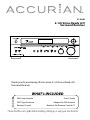
31-5048
6.1ch Sirius-Ready A/V
Surround Receiver
Thank you for purchasing this Accurian 6.1 ch Sirius-Ready A/V
Surround Receiver.
WHAT’s INCLUDED
AM Loop Antenna
FM T-Type Antenna
Remote Control
User’s Guide
Adapter for FM Antenna
Batteries for Remote Control (2)
Please read this user’s guide before installing, setting up, or using your new Receiver
CAUTION: TO REDUCE THE RISK OF ELECTRIC SHOCK, DO
NOT REMOVE COVER (OR BACK). NO USER SERVICEABLE
PARTS INSIDE. REFER SERVICING TO QUALIFIED SERVICE
PERSONNEL.
This symbol is intended to alert the user to the presence
of uninsulated dangerous voltage within the product’s
enclosure that may be of sufficient magnitude to
constitute a risk of electric shock.
This symbol is intended to alert the user to the
presence of important operating and maintenance
(servicing) instructions in the literature accompanying
this device.
WARNING: TO PREVENT FIRE OR SHOCK HAZARD, DO NOT
EXPOSE THIS APPLIANCE TO RAIN OR MOISTURE.
The equipment draws nominal nonoperating power from the AC
outlet with its POWER switch in the STANDBY position.
For CANADA
CAUTION - TO PREVENT ELECTRIC SHOCK, MATCH WIDE BLADE
OF PLUG TO WIDE SLOT, FULLY INSERT.
CAUTION Regarding Placement
To maintain proper ventilation, be sure to leave a space
around the unit (from the largest outer dimensions including
projections) equal to, or greater than, shown below.
Left and Right Panels : 4 inches (10 cm)
Rear Panel : 4 inches (10 cm)
Top Panel : 20 inches (50 cm)
2
IMPORTANT SAFETY INSTRUCTIONS
1. Read Instructions — All the safety and operating instructions should be read before the
product is operated.
2. Retain Instructions — The safety and operating instructions should be retained for future
reference.
3. Heed Warnings — All warnings on the product and in the operating instructions should
be adhered to.
4. Follow Instructions — All operating and use instructions should be followed.
5. Cleaning — Unplug this product from the wall outlet before cleaning. Do not use liquid
cleaners or aerosol cleaners. Use a damp cloth for cleaning.
6. Attachments — Do not use attachments not recommended by the product manufacturer
as they may cause hazards.
7. Water and Moisture — Do not use this product near water – for example, near a bath tub,
wash bowl, kitchen sink, or laundry tub; in a wet basement; or near a swimming pool; and
the like.
8. Accessories — Do not place this product on an unstable cart, stand, tripod, bracket, or
table. The product may fall, causing serious injury to a child or adult, and serious damage
to the product. Use only with a cart, stand, tripod, bracket, or table recommended by the
manufacturer, or sold with the product. Any mounting of the product should follow the
manufacturer’s instructions, and should use a mounting accessory recommended by the
manufacturer.
9. A product and cart combination should be moved with care. Quick stops, excessive force,
and uneven surfaces may cause the product and cart combination to overturn.
10. Ventilation — Slots and openings in the cabinet are provided for ventilation and to ensure
reliable operation of the product and to protect it from overheating, and these openings
must not be blocked or covered. The openings should never be blocked by placing the
product on a bed, sofa, rug, or other similar surface.
This product should not be placed in a built-in installation such as a bookcase or rack
unless proper ventilation is provided or the manufacturer’s instructions have been
adhered to.
11. Power Sources — This product should be operated only from the type of power source
indicated on the marking label. If you are not sure of the type of power supply to your
home, consult your product dealer or local power company. For products intended to
operate from battery power, or other sources, refer to the operating instructions.
12. Grounding or Polarization — This product may be equipped with a polarized alternating-
3
current line plug (a plug having one blade wider than the other). This plug will fit into
the power outlet only one way. This is a safety feature. If you are unable to insert the
plug fully into the outlet, try reversing the plug. If the plug should still fail to fit, contact
your electrician to replace your obsolete outlet. Do not defeat the safety purpose of the
polarized plug.
13. Power-Cord Protection — Power-supply cords should be routed so that they are not likely
to be walked on or pinched by items placed upon or against them, paying particular
attention to cords at plugs, convenience receptacles, and the point where they exit from
the product.
14. Outdoor Antenna Grounding — If an outside antenna or cable system is connected to
the product, be sure the antenna or cable system is grounded so as to provide some
protection against voltage surges and built-up static charges. Article 810 of the National
Electrical Code, ANSI/NFPA 70, provides information with regard to proper grounding of
the mast and supporting structure, grounding of the lead-in wire to an antenna discharge
unit, size of grounding conductors, location of antenna-discharge unit, connection to
grounding electrodes, and requirements for the grounding electrode.
NOTE TO CATV SYSTEM INSTALLER:
This reminder is provided to call the CATV (Cable TV) system installer’s attention to
article 820-40 of the NEC that provides guidelines for proper grounding and, in particular,
specifies that the cable ground shall be connected to the grounding system of the
building, as close to the point of cable entry as possible.
15. Lightning — For added protection for this product during a lightning storm, or when it is
left unattended and unused for long periods of time, unplug it from the wall outlet and
disconnect the antenna or cable system. This will prevent damage to the product due to
lightning and power-line surges.
16. Power Lines — An outside antenna system should not be located in the vicinity of
overhead power lines or other electric light or power circuits, or where it can fall into such
power lines or circuits. When installing an outside antenna system, extreme care should be
taken to keep from touching such power lines or circuits as contact with them might be
fatal.
17. Overloading — Do not overload wall outlets, extension cords, or integral convenience
receptacles as this can result in risk of fire or electric shock.
4
18. Object and Liquid Entry — Never push objects of any kind into this product through
openings as they may touch dangerous voltage points or short-out parts that could result
in a fire or electric shock. Never spill liquid of any kind on the product.
19. Servicing — Do not attempt to service this product yourself as opening or removing
covers may expose you to dangerous voltage or other hazards. Refer all servicing to
qualified service personnel.
20. Damage Requiring Service — Unplug this product from the wall outlet and refer servicing
to qualified service personnel under the following conditions:
a. When the power-supply cord or plug is damaged.
b. If liquid has been spilled, or objects have fallen into the product.
c. If the product has been exposed to rain or water.
d. If the product does not operate normally by following the operating instructions.
Adjust only those controls that are covered by the operating instructions as an
improper adjustment of other controls may result in damage and will often require
extensive work by a qualified technician to restore the product to its normal
operation.
e. If the product has been dropped or damaged in any way.
f.
When the product exhibits a distinct change in performance — this indicates a need
for service.
21. Replacement Parts — When replacement parts are required, be sure the service
technician has used replacement parts specified by the manufacturer or have the same
characteristics as the original part. Unauthorized substitutions may result in fire, electric
shock, or other hazards.
22. Safety Check — Upon completion of any service or repairs to this product, ask the service
technician to perform safety checks to determine that the product is in proper operating
condition.
23. Wall or Ceiling Mounting — The product should be mounted to a wall or ceiling only as
recommended by the manufacturer.
24. Heat — The product should be situated away from heat sources such as radiators, heat
registers, stoves, or other products (including amplifiers) that produce heat.
5
Contents
IMPORTANT SAFETY INSTRUCTIONS ................................... 3
Introducing SIRIUS Satellite Radio ....................................... 8
Getting Started
9
Before Operating Your Product ............................................. 9
Connecting Speakers ..............................................................10
Connecting Your Amplifier/Receiver
11
Pre Out and Speakers...............................................................11
Choosing a Location for Your Speakers ............................12
Audio Components ..................................................................15
Video Components ..................................................................17
Connecting Antennas ..............................................................19
Connecting the Sirius Home Tuner .....................................22
AC Power Cord............................................................................23
Front Panel Controls
Remote Control
24
26
Remote Sensor ...........................................................................29
Battery Installation ....................................................................30
Advanced Operation
31
Recording a Source ...................................................................32
TONE Control .............................................................................32
Muting ..........................................................................................32
Sleep Timer Function ..............................................................33
NIGHT MODE Function ...........................................................33
DIMMER .......................................................................................33
Radio Reception
34
FM MODE......................................................................................35
Presetting
36
Automatic Memory Presetting .............................................36
Manual Memory Presetting ..................................................37
6
SIRIUS Satellite Radio Tuner
Video Operations
37
42
VCR Dubbing ..............................................................................42
Deck Dubbing ............................................................................43
OSD Function ..............................................................................43
Speaker Configuration
44
Size of Speakers ........................................................................45
Balancing Speaker Relative Volume (Output Level) .....47
Input the Distance From Your Listening Position .........47
Balancing Speaker Relative Volume ...................................48
Surround Modes
48
Selecting a Surround Mode ..................................................52
Setting up Surround Modes .................................................52
Surround Mode and the Input Signal ................................53
STEREO Mode ............................................................................55
Troubleshooting
Specifications
56
58
7
Introducing SIRIUS Satellite Radio
With over 120 channels of the best entertainment and completely
commercial-free music for your car, home or office. Only SIRIUS has
more than 65 original music channels, from today’s hits to R&B oldies to
classical masterpieces. From authentic country and real bluegrass to cool
jazz, hot Latin, Reggae, rock and many more. Best of all, it’s all completely
commercial-free.
SIRIUS also has more than 55 channels of world-class sports, news and
entertainment. Included as part of your subscription, you get up to 16 NFL
games a week, up to 40 NBA games a week and up to 40 NHL games a
week, (Games are broadcast during their respective seasons.), coupled with
great sports news from ESPN, the SIRIUS sports offering is unrivaled. And
don’t forget a host of other great news and entertainment, like NPR, CNBC,
Fox News, Radio Disney and E! Entertainment Radio. For more information,
visit www.sirius.com.
How to Subscribe
This unit is Sirius-ready. It requires a Sirius Connect™ Home Tuner
(purchased separately) and a Sirius Satellite Radio subscription is needed
to listen to the Sirius Satellite Radio. For more information, visit
https://activate.siriusradio.com.
About the SIRIUS Mark
SIRIUS Satellite Radio Ready
© 2006 SIRIUS Satellite Radio Inc. "SIRIUS" and the
SIRIUS dog logo are registered trademarks of SIRIUS
Satellite Radio Inc.
8
Getting Started
Before Operating Your Product
• Choose your installation location carefully. Avoid placing it in direct
sunlight or close to a source of heat. Also avoid locations subject to
vibrations and excessive dust, heat, cold, or moisture.
• Do not cover the ventilation hole. Make sure there is enough space
above and beside the amplifier/receiver. Do not place a CD player or
other equipment on top of the amplifier/receiver.
• Do not open the cabinet as this might result in damage to the circuitry or
electrical shock. If a foreign object should get into the set, contact your
local RadioShack® store.
• When removing the power plug from the wall outlet, always pull directly
on the plug, never yank the cord.
• Do not attempt to clean the unit with chemical solvents as this might
damage the finish. Use a clean, dry cloth.
• Keep this manual in a safe place for future reference.
Caution
• Turn off the power of all the equipment before making connections.
• Read instructions of each component you intend to use with this unit.
• Be sure to insert each plug securely. To prevent hum and noise, do not
bundle the connection cords with the power cord or speaker cord.
• Do not connect this unit and other components or to the main power
until all connections between components have been completed.
9
Connecting Speakers
Caution: To avoid damaging the speakers with a sudden high-level
signal, be sure to switch the power off before connecting the speakers.
• Check the impedance of your speakers.
• Connect speakers with an impedance of 6 ohms or more.
• The amplifier’s red speaker terminals are the positive (+) terminals and
the black terminals are the negative (-) terminals.
• The + side of the speaker cable is marked to make it distinguishable from
the - side of the cable. Connect this marked side to the red + terminal
and the unmarked side to the black terminal.
• Prepare the speaker cords for connection by stripping off approximately
10 mm or less (no more, as this could cause a short circuit) of the outer
insulation. Twist the wires tightly together so that they do not fray:
How to Connect
1.
Loosen the knob by turning it counterclockwise.
2.
Insert the bare part of the wire into the hole inside of each terminal.
3.
Tighten the knob by turning it clockwise to secure the wire.
Note: Make sure the cord is fastened securely by pulling it lightly.
10
Connecting Your Amplifier/Receiver
Pre Out and Speakers
(OPTIONAL)
POWERED
SUBWOOFER
FRONT
CENTER
RIGHT
LEFT
LEFT
RIGHT
SURROUND
BACK
RIGHT
RIGHT
LEFT
LEFT
SURROUND
PRE OUT (SUB WOOFER) Jack
Use this jack to connect a powered sub woofer (power amplifier built in). If
your sub woofer is a passive type (power amplifier is not built in), connect a
monaural power amplifier to the PRE OUT jack and connect the sub woofer
to the amplifier.
11
AC OUTLET
This outlet is only active when the receiver is turned on.
Caution: Make sure that the total power consumption of all equipment
connected to the outlets on the receiver does not exceed 100 watts.
Choosing a Location for Your Speakers
Placing Your Speakers
Subwoofer
Surround Left
Front Left
Front Center
0
Surround
Back
45-60
110
Surround Right
Front Right
90
The ideal surround speaker system for this unit is 6.1 speaker system, using
front left and right speakers, a center speaker, surround left and right
speakers, a surround back speaker, and a subwoofer.
For best results we recommend that front speakers be of the same type,
with identical or similar driver units. This will deliver smooth pans across
the front sound stage as the action moves from side to side.
Your center channel speaker is very important as over 80% of the dialog
from a typical motion picture emanates from the center channel. It should
possess similar sonic characteristics to the main speakers. Surround
channel speakers need not be identical to the front channel speakers, but
they should be of high quality.
12
Bass effects are an important part of home theater. For optimal enjoyment,
a subwoofer should be used as it is optimized for low frequency
reproduction. If you have full range front speakers, however, they may be
used in place of a subwoofer with proper setting of the switches in the
menu system.
Front Left and Right Speakers
We recommend to set the front L and R speakers with 45-60 degrees from
the listening position.
Center Speaker
Align the front line of the center speaker with the front L/R speakers. Or
place the center speaker a little backward from the line.
Surround Left and Right Speakers
When the receiver is used in surround operation, the preferred location for
surround speakers is on the side walls of the room, at or slightly behind the
listening position. The center of the speaker should face into the room.
Surround Back Speakers
Surround back speaker is required when a 6.1-channel system is installed.
The speaker should be placed on a rear wall, behind the listening position.
The center of the speaker should face into the room.
Subwoofer (Optional)
We recommend using a subwoofer to have maximum bass effect. The
subwoofer bears only low frequency range so you can place it anywhere in
the room.
13
Height of the Speaker Units
Front Left and Right Speakers, and a Center Speaker
Align the tweeters and mid-range drivers on the three front speakers at the
same height, as best as possible.
Surround Left and Right Speakers, and Surround Back Speaker
Place the surround left, right and surround back speakers higher than your
ears by about 2.4-3.5’ (70 cm – 1 m). Also place the speakers at the same
height, as best as possible.
2.4-3.5’
(0.7-1 m)
Note: Use magnetically-shielded speakers for the front left, right and
center speakers when the speakers are installed near the TV and the TV is
a monitor type.
14
Audio Components
TAPE DECK
AUDIO
OUT
R
L
DIGITAL
IN
AUDIO
IN
R
L
DIGITAL
OUT
DVD RECORDER
Tape Jacks
The audio output signal from the TAPE OUT (L/R) jack is the input jack (L/R)
signal which is currently selected.
Notes:
• Insert all plugs and connectors securely. Incomplete connections
may make noise.
• Be sure to connect the left and right channels properly. Red
connectors are for the R (right) channel, and white connectors
are for the L (left) channel.
15
Connecting Digital Audio Components
•
There are digital input jacks on the rear panel. You can use these
jacks to input PCM, Dolby Digital and DTS bitstream signals from a
CD, DVD, or other digital source components.
•
There is one digital optical output jack on the rear panel. The jack
can be connected to a CD recorder, DVD recorder, or MD deck
inputs, respectively.
•
To set up the digital audio format of DVD player, or other digital
sources connected to digital input jacks, refer to the instructions of
each component.
•
You can designate the input for each digital input/output jack
according to your component.
Notes:
• There is no Dolby Digital RF input jack. Please use an external RF
demodulator Dolby Digital decoder when connecting the Dolby
Digital RF output jack of the video disc player to the digital input
jack.
• The digital signal jacks on this unit conform to the EIA standard.
If you use a cable that does not conform to this standard, this
unit may not function properly.
• Each type of audio jack works independently. Signals input
through the digital and analog jacks are output through the
corresponding digital and analog jacks, respectively.
• Digital input signals from the coaxial jack are also output from
the optical jack.
16
Video Components
DVD PLAYER
AUDIO
OUT
R
R
COMPONENT
VIDEO OUT
L
L
Y
R
IN
OUT
AUDIO
Pb
Pr
DIGITAL
OUT
VIDEO
OUT
Y
L
IN OUT OUT IN
VIDEO S-VIDEO
VCR
S-VIDEO
OUT
Pb
Pr
COMPONENT
VIDEO IN
S-VIDEO
IN
VIDEO MONITOR OR PROJECTOR
VIDEO, S-VIDEO, COMPONENT Jacks
There are 3 types of video jacks on the rear panel.
VIDEO Jack
The video signal for the VIDEO jacks is the conventional composite video
signal.
17
S-VIDEO Jack
The video signal is separated into luminance (Y) and color (C) signals
for the S-VIDEO jack. The S-VIDEO signals enable high-quality color
reproduction. If your video component has an S-VIDEO output, we
recommend to use it. Connect the S-VIDEO output jack on your video
component to the S-VIDEO input jack on this unit.
COMPONENT Jack
Make component video connections to a TV or monitor with component
inputs to produce higher quality video images. Use a component video
cable or 3 video cords to connect the component video out jacks on the
receiver to the monitor.
Video Convert
The receiver converts S-Video input signals to a video output signal. For
example, the S-Video input signal can be output to the receiver’s MONITOR
OUT VIDEO jack.
Notes:
• Be sure to connect the left and right audio channels properly. Red
connectors are for the R (right) channel, and white connectors
are for the L (left) channel.
• Be sure to connect the inputs and outputs of the video signals
properly.
• If you connect the S-VIDEO or component signal to the S-VIDEO
or component jack on this unit, it is not necessary to connect
the conventional video signal to the VIDEO (composite) jack. If
you use both video inputs, this unit gives priority to the S-VIDEO
signal.
• Each type of video jack works independently. Signals input to the
VIDEO (composite), S-VIDEO or component jacks are output to
the corresponding VIDEO (composite), S-VIDEO, or component
jacks, respectively.
• You may need to set up the digital audio output format of your
DVD player, or other digital source components. Refer to the
instructions of each component connected to the digital input
jacks.
18
Connecting Antennas
AM loop
antenna
FM antenna
AM external
antenna
FM external
antenna
Assembling the AM Loop Antenna
1.
Release the vinyl tie and take out the connection line.
2.
Bend the base down in the reverse direction.
19
3.
Insert the hook at the bottom of the loop part into the slot at the
base.
4.
Place the antenna on stable surface.
Connecting the Supplied Antennas
Connecting the Supplied FM Antenna
The supplied FM antenna is for indoor use only. During use, extend the
antenna and move it in various directions until you receive the clearest
signal.
Fix it with push pins or similar implements in the position that will cause
the least amount of distortion.
If you experience poor reception quality, an outdoor antenna may improve
the quality.
Connecting the Supplied AM Loop Antenna
The supplied AM loop antenna is for indoor use only. Set it in the direction
and position it to where you receive the clearest sound. Put it as far away as
possible from the unit, televisions, speaker cables, and power cords.
If you experience poor reception quality, an outdoor antenna may improve
the quality.
1.
Press and hold down the lever of the AM antenna terminal.
2.
Insert the bare wire into the antenna terminal.
3.
Release the lever.
20
Connecting an FM Outdoor Antenna
Notes:
• Keep the antenna away from noise sources (neon signs, busy
roads, etc.).
• Do not put the antenna close to power lines. Keep it well away
from power lines, transformers, etc.
• To avoid the risk of lightning and electrical shock, grounding is
necessary.
Connecting an AM Outdoor Antenna
An outdoor antenna will be more effective if it is stretched horizontally
above a window or outside.
Notes:
• Do not remove the AM loop antenna.
• To avoid the risk of lightning and electrical shock, grounding is
necessary.
21
Connecting the Sirius Home Tuner
SIRIUS HOME TUNER
SIRIUS ANTENNA
COAXIL CABLE
8P MINI DIN CABLE
Using SIRIUS Radio
SIRIUS delivers more than 120 channels of the best commercial-free music,
compelling talk shows, news and information, and the most exciting sports
programming to listeners across the country in digital quality sound.
SIRIUS offers 65 channels of 100% commercial-free music, and features
over 55 channels of sports, news, talk, entertainment, traffic and weather
for a monthly subscription. SIRIUS also broadcasts live play-by-play games
of the NFL and NBA, and is the Official Satellite Radio partner of the NFL.
Connecting Your SIRIUS Radio Receiver
Connect the SIRIUS home tuner (not supplied, available at your local
RadioShack store) to the SIRIUS IN jack on the rear of this receiver. You will
also need to activate the SIRIUS Radio service. For best reception, you may
need to move the SIRIUS antenna near a window (refer to the Installation
Guide of the SIRIUS home tuner).
22
To display the signal strength, press OSD once.
Connect the SIRIUS home tuner to your receiver using the 8-pin mini DIN
cable. Your receiver provides the power to the SIRIUS home tuner through
the 8-pin mini DIN cable. You do not need to connect the AC adapter to the
Sirius home tuner. However, we recommend using the AC adapter for less
noise.
You can use the OPTICAL IN jack to connect an optical cable (not supplied)
to receive audio signals from the SIRIUS home tuner. When you use the
optical cable, leave the 8-pin mini DIN cable connected and set the input
mode to digital by pressing ANALOG/DIGITAL SELECT.
Notes:
• The SIRIUS OPTICAL IN jack is only for the SIRIUS home tuner.
• Before making or changing the connections, switch off the power
and disconnect the power cord from the power outlet. Plugging
in components should be the last connection you make with
your system.
• Do not allow any contact between speaker wires from different
terminals.
AC Power Cord
Be sure to connect the power cord to an AC outlet that supplies the correct
voltage.
Hold the power plug when plugging or unplugging the power cord.
23
Front Panel Controls
STANDBY/ON
Press to switch the unit between standby and on.
Power Indicator
This LED lights red when the unit is in the standby mode to signal that the
unit is ready to be turned on, when the unit is in operation, the indicator is
off.
PHONES
Use to connect headphones.
MP3 INPUT 2
Use to connect equipment like an MP3 player.
FM MODE
Use to select stereo or mono mode while listening to FM broadcasts.
MEMORY
In tuner mode, use to program preset radio stations.
TUNING MODE
Press to select manual or preset tuning mode.
24
TUNING/PRESET
In tuner mode, use to tune in stations.
ANALOG/DIGITAL SELECT
Repeatedly press to select one of the digital inputs or the analog input for
any source.
TONE
Use to adjust the level of bass and treble.
INPUT SELECT
Use to select functions.
VOLUME
Turn to adjust the volume.
ENTER
When making a choice during the setup or configuration process, press to
enter the desired setting.
In SIRIUS function, press to select items on the display.
CH (S/T)
Use to navigate through channels or menus.
CAT (e/f)
Use to navigate through categories or menus.
SAT-MEMO (Only SIRIUS Function)
In SIRIUS mode, press to program preset SIRIUS stations.
MODE (Only SIRIUS Function)
Press to select normal mode, skip mode or band mode.
DISPLAY (Only SIRIUS Function)
Press to select channel information or category information.
25
SET UP
Press to begin the process of configuring the unit to match the type of
speakers used in your listening room.
SURROUND
Use to select from the various surround modes.
STEREO
Use to select stereo mode or surround mode.
Display Window
Depending on the unit’s status, a variety of messages will appear here.
SATELLITE RADIO (SIRIUS Function Direct Button)
Use to select SIRIUS Satellite Radio function.
Remote Control
STANDBY
Press to switch the unit between standby and on.
26
Function Buttons (TUNER, TAPE, VCR, DVD, AUX, MP3-1, MP3-2,
SIRIUS)
Use these to select function modes.
Numeric Buttons (0-9)
Use to enter tuner preset positions.
STEREO
Use to select stereo mode or surround mode.
SET UP
Press to begin the process of configuring the unit to match the type of
speakers used in your listening room.
CLEAR
Use to remove a programmed preset radio station.
OSD (Only SIRIUS Function)
Use to display Sirius Satellite Radio Information on screen. As you press
OSD, the display switches as shown below.
CHANNEL INFORMATION
SIRIUS SETUP
OFF
ENTER
When making a choice during the setup or configuration process, press to
enter the desired setting.
In Sirius function, press to select items on the display.
Navigation Buttons
Use to select options on set up and Sirius function.
- CH (S/T): Use to navigate through channels or menus.
- CAT (e/f): Use to navigate through categories or menus.
MODE (Only SIRIUS Function)
Press to select skip mode or band mode. As you press MODE, the mode
changes:
NORMAL MODE
SKIP MODE
27
BAND MODE
TUNING MODE
Press to select manual or preset tuning.
TEST TONE
Use to output the test tones for setting speaker levels.
NIGHT
When very dynamic movie soundtracks are played at low volume, such as
late at night, you can use night mode to apply appropriate compression
so that low-level program content is not lost and high level effects are
restrained. (DOLBY DIGITAL only)
TUNING/PRESET (T/S)
- When the tuner is in use, use to tune up or down through the selected
frequency band.
- Press to select a tuner preset channel.
MEMORY
In tuner mode, press to program preset radio stations.
FM/AM
Press to select AM or FM.
FM MODE
Press to select stereo or mono mode while listening to FM broadcasts.
SAT-MEMO (Only SIRIUS Function)
In Sirius mode, press to program preset Sirius stations.
DISPLAY (Only SIRIUS Function)
Press to select channel information or category information.
ANALOG/DIGITAL SELECT
Repeatedly press to select one of the digital inputs or the analog input for
any source.
TONE
Use to adjust the level of bass and treble.
28
SURROUND
Use to select from the various surround modes.
VOLUME (+/-)
Press to adjust volume.
MUTE
Press to activate the mute function.
DIMMER
Press to adjust the brightness of the front display.
SLEEP
Press to set the sleep timer.
Send Indicator
Lights red when sending a signal.
Remote Sensor
Remote Sensor Window
of the Receiver
By using the provided remote control, you can control the receiver from
your listening position. To use the remote control, point it at the remote
sensor window located in the right side of the receiver’s display.
Notes:
• Even if the remote control is operated within the effective range,
remote control operation may be impossible if there are any
obstacles between the unit and the remote control.
• If the remote control is operated near other appliances which
generate infrared rays, or if other remote control devices using
infrared rays are used near the unit, it may operate incorrectly.
Conversely, the other appliances may operate incorrectly.
29
Battery Installation
1.
Remove the battery compartment cover.
2.
Insert the supplied two “AAA” batteries. Make sure that the
batteries are inserted with their positive “+” and negative “-” poles
positioned correctly.
3.
Close the cover until it clicks.
If the distance required between the remote control and main unit
decreases, replace the batteries with new ones.
Precautions Concerning Batteries
• Use batteries of the same type. Never use different types of batteries
together.
•
Rechargeable or non-rechargeable batteries can be used. Refer to
the precautions on their labels.
•
When the remote control is not to be used for a long time (more
than a month), remove the batteries from the remote control to
prevent them from leaking. If they leak, wipe away the liquid inside
the battery compartment and replace the batteries with new ones.
•
Do not heat or disassemble batteries and never dispose of old
batteries by throwing them in a fire.
30
Advanced Operation
STANDBY/ON
INPUT SELECT
CH
TONE
ANALOG/
DIGITAL SELECT
STANDBY
VOLUME
SLEEP
DIMMER
MUTE
VOLUME
ANALOG/
DIGITAL SELECT
NIGHT
1.
Press STANDBY/ON.
2.
Select the desired source with INPUT SELECT.
TUNER (FM, AM)
SIRIUS (OPTICAL, ANALOG)
AUX (COAXIAL, ANALOG)
DVD (OPTICAL, ANALOG)
VCR
TAPE
MP3 (1, 2)
31
3.
When DVD is selected, press ANALOG/DIGITAL SELECT to select
OPTICAL or ANALOG in accordance with your connections.
4.
When AUX is selected, press ANALOG/DIGITAL SELECT to select
COAXIAL or ANALOG in accordance with your connections.
Recording a Source
You can record a source such as a Compact Disc onto a cassette tape
connected to the TAPE OUT jacks.
1.
Turn INPUT SELECT corresponding to the source to be recorded.
2.
Press ANALOG/DIGITAL SELECT to select ANALOG.
3.
Start recording.
TONE Control
1.
2.
Repeatedly press TONE to select BASS or TREBLE.
• To adjust the level of low frequency sound range, select “BASS”.
• To adjust the level of high frequency sound range, select
“TREBLE”.
Press CH T/S or VOLUME +/- of the remote control or the front
panel to adjust the level. The level can be adjusted in 1dB steps
from -10 to +10.
Muting
To mute the sound temporarily, press MUTE. Press MUTE again to restore
the sound. If you change the volume during the muting, the muting will be
canceled.
32
Sleep Timer Function
This function allows you to preprogram the receiver to switch its own
power off automatically. You can then enjoy the audio/video system for a
specified amount of time without having to worry about turning the unit
off later. Each press of SLEEP changes the time indication by 10 minutes.
To let the remaining time (until power off ) appear on the display while the
sleep timer is engaged, press SLEEP once.
NIGHT MODE Function
When very dynamic movie soundtracks are played at low volume, such as
late at night, you can use night mode to apply appropriate compression
so that low-level program content is not lost and high level effects are
restrained. (DOLBY DIGITAL only)
DIMMER
You can adjust the brightness of the front display. When DIMMER ON is
shown, all of the front panel indicators will go dark.
When DIMMER OFF is shown, the display is at its normal brightness.
33
Radio Reception
TUNING/PRESET
TUNING MODE
INPUT SELECT
FM MODE
TUNER
FM/AM
FM MODE
TUNING MODE
TUNING/PRESET
1.
Select the TUNER mode by turning INPUT SELECT or press TUNER
on the remote control.
2.
Select AM or FM by pressing FM/AM or turning INPUT SELECT.
3.
Press TUNING MODE to change to TUNING mode. This button is
used to select MANUAL or PRESET scan mode.
4.
Hold down TUNING/PRESET or for 0.5 to 2 seconds. The tuner
automatically searches for a station. When a station is tuned in, the
tuning process will stop automatically. Press TUNING/PRESET or
to stop the auto selection.
34
Or repeatedly press TUNING/PRESET or to manually select a
station. The frequency changes by a fixed step (FM: 100 kHz, AM: 10
kHz steps).
Note: During AM reception, PURE STEREO or DSP STEREO appears on the
receiver’s display if the stereo mode is selected using STEREO. However,
the tuner receives mono and the sound does not change from mono to
stereo.
FM MODE
Pressing this button alternates between stereo mode and mono mode.
Stereo
FM stereo broadcasts are received in stereo and FM MODE STEREO appears
on the display. If FM broadcasts with weak signal strength are received,
the FM muting function works automatically to cut the signals, eliminating
loud noise.
Mono
To compensate for weak FM stereo reception, select this mode. Reception
will now be forced monaural, reducing unwanted noise.
35
Presetting
TUNING/PRESET
INPUT SELECT
MEMORY
TUNER
FM/AM
MEMORY
TUNING/PRESET
This feature is used to store FM, AM broadcasting from Channel 1 to 30
respectively.
Automatic Memory Presetting
1.
Select the tuner mode by turning INPUT SELECT or pressing
TUNER on the remote control.
2.
Select the AM or FM by pressing FM/AM or turning INPUT SELECT.
3.
Press MEMORY for more than 2 seconds. Up to 30 of the best
received stations in your area will be automatically stored.
36
Manual Memory Presetting
1.
Select the tuner mode by turning INPUT SELECT or pressing
TUNER on the remote control.
2.
Select the AM or FM by pressing FM/AM or turning INPUT SELECT.
3.
Press TUNING MODE to change the tuning mode from preset to
manual.
4.
Select the frequency you want to preset by pressing TUNING/
PRESET or .
5.
Press MEMORY briefly.
6.
While P_ _ is flickering, select a preset channel to store the station
using TUNING/PRESET or , and then press MEMORY.
To store more stations, repeat Steps 3 to 6.
SIRIUS Satellite Radio Tuner
Sirius ID
During the process of activating your Sirius subscription, you will need to
provide your Sirius ID.
Press OSD on the remote control twice to display your Sirius ID.
Basic Operation
1.
After you have successfully activated your SIRIUS subscription, the
Normal Operation (Default) information will appear (below) on the
receiver’s display.
CHANNEL NUMBER
(3 digit)
001 Hits1
_ _ POP
BAND PRESET
(2 Character)
2.
CHANNEL NAME
(Max:8 Character)
CATEGORY NAME
(Max:8 Character)
Use CH T or S to select channels.
37
3.
Repeatedly press OSD. The display toggles:
CHANNEL INFORMATION -> SIRIUS SETUP -> Off
OSD DISPLAY
*CHANNEL INFORMATION*
CHANNEL: 001/Hits 1
* CATEGORY: NAME
ARTIST/COMPOSER
: The Darkness
SONG TITLE
: Toxic
S-MODE: NORMAL
ANTENNA: EXCELLENT
:CHANNEL NAME
:CATEGORY NAME
:ARTIST/COMPOSER
:SCROLL, DISPLAY
:SONG TITLE
:SCROLL, DISPLAY
:NORMAL,SKIP,BAND
:ANTENNA STRENGTH
:ERROR, SURR MODE, VOLUME MESSAGE
Channel Up/Down
1.
Pressing CH S will increment or move up to the next channel.
2.
Pressing CH T will decrement or move down to the next channel.
020 Octane
_ _ ROCK
CH UP
021 Alt Hatn
_ _ ROCK
CH DOWN
020 Octane
_ _ ROCK
Direct Tuning
1.
Channels can also be directly accessed by pressing 0-9 to
numerically enter the desired channel.
2.
Once the desired channel number has been entered, the channel
will change and the display will revert to the new channel.
Note: The receiver will change immediately if three numbers are entered
(example. 0, 0, 5). However, if just one or two digits are entered (example:
7, 7, ENTER), the unit will change to that channel 5 seconds after the last
number was entered.
38
Display Setting
Pressing DISPLAY from the default display toggles:
CATEGORY name -> ARTIST/COMPOSER name -> SONG TITLE name
FL DISPLAY
001 Hits1
DISPLAY
_ _ POP
001 Hits1
DISPLAY
_ _ Britney Spear
001 Hits1
_ _ Toxic
Category Up/Down
1.
If you want to listen to a different entertainment category, press
CAT e or f to activate the category.
- First channel display in the next category.
FL
FL DISPLAY
DISPLAY
001 Hits1
CAT
_ _ POP
014 ClsViny1
CAT
_ _ ROCK
001 Hits1
_ _ POP
OSD DISPLAY
CATEGORY: POP
* 014 CHANNEL NAME
002 CHANNEL NAME
003 CHANNEL NAME
2.
CATEGORY: POP
CATEGORY: ROCK
* 001 CHANNEL NAME
* 001 CHANNEL NAME
002 CHANNEL NAME
015 CHANNEL NAME
CAT
016 CHANNEL NAME
CAT
003 CHANNEL NAME
004 CHANNEL NAME
017 CHANNEL NAME
004 CHANNEL NAME
DISPLAY MODE: CHANNEL
DISPLAY MODE: CHANNEL
DISPLAY MODE: CHANNEL
Repeatedly press DISPLAY to switch between the following:
CHANNEL NAME LIST -> ARTIST NAME LIST -> TITLE NAME LIST
3.
Press MODE (or leave the unit for 10 seconds) to exit the category
mode.
39
Setting Skip Channel
1.
Press MODE.
2.
Press ENTER to set the channel skip mode.
• To cancel, press ENTER.
• If you do not operate the function within 10 seconds, the
display automatically returns to the normal display.
FL DISPLAY
005 Gold
ENTER
005 Gold
SKIP CH 005
SKIP MODE
OSD
DISPLAY
OSD DISPLAY
*CHANNEL INFORMATION*
CHANNEL: 005/Gold
* CATEGORY: NAME
ARTIST/COMPOSER
: The Beach Boys
SONG TITLE
: Catch A Wave
*S-MODE: SKIP
ANTENNA: EXCELLIENT
*CHANNEL INFORMATION*
ENTER
CHANNEL: 005/Gold
* CATEGORY: NAME
ARTIST/COMPOSER
: The Beach Boys
SONG TITLE
: Catch A Wave
*S-MODE: SKIP ch 005
ANTENNA: EXCELLIENT
Setting Channel Presets
You can store up to 30 of your favorite channels as preset for quick access.
Presets are stored in 3 banks, A, B and C, each containing 10 channel
presets. If A0 has a memorized channel, the previously memorized channel
is removed and a new channel is stored.
1.
Select the channel you want to memorize.
2.
Press SAT-MEMO.
3.
Press CH S or T to select one of the three banks.
4.
Press SAT-MEMO.
Example: To memory CHANNEL 010 to BAND A0
010 Bridge
_ _ POP
SAT-MEMO
010 Bridge
A0
SAT-MEMO
MEMORY
010 Bridge
A0 POP
40
Example: To memory 010 CH to BAND C5
010 Bridge
SAT-MEMO 010 Bridge
C5
_ _ POP
SAT-MEMO
MEMORY
010 Bridge
C5 POP
Searching Channel Presets
1.
Press MODE twice.
2.
Press CH S or T to the choose desired channel within 30 of the
preset channels.
3.
To return to the normal display, press MODE.
Sirius Set Up
1.
Press OSD twice. The SIRIUS ID is displayed.
2.
If you want to choose SIRIUS RESET, clear all the BAND PRESET or
clear Skip Channel setting, press f to select YES.
3.
Press ENTER.
FL DISPLAY
ESN-SIRIUS ID
button
ESN-SIRIUS ID
ENTER
SIRIUS RESET:YES
SIRIUS RESET: NO
ESN-SIRIUS ID
RESET PROCESS
OSD DISPLAY
*SIRIUS SETUP*
*SIRIUS SETUP*
SIRIUS ID: XXXXXXXXXXXX
RESET: NO
*SIRIUS SETUP*
WARNING!
button
WARNING!
ENTER
PLESE WAIT!!
>>>>>>>>>>>>>
41
PLESE WAIT!!
>>>>>>>>>>>>>
Error Messages
When problems occur with your SIRIUS tuner, a message appears on the
display.
State
FL Display
Home Tuner is not connected
CHECK SIRIUS TUNER
Antenna is not connected
CHECK SIRIUS
NO ANTENNA.
Sirius satellite no signal
SIRIUS RADIO
ACQUIRING SIGNAL
Video Operations
INPUT SELECT
VCR Dubbing
(From AUX or DVD to VCR)
1.
Turn INPUT SELECT to select the source (AUX or DVD) to be
recorded. If necessary, press ANALOG/DIGITAL SELECT to select
ANALOG.
2.
Play back the source (AUX or DVD).
3.
Operate the VCR for recording. Video/audio signals from the
selected VIDEO source can be dubbed to VCR OUT.
Note: When VCR dubbing is performed, be sure to connect the VCR to VCR
OUT (analog audio output).
42
Deck Dubbing
(From AUX or DVD or VCR to Tape)
1.
Turn FUNCTION (source) to select the audio source (AUX, DVD, or
VCR) to be recorded. If necessary, press ANALOG/DIGITAL SELECT
to select ANALOG.
2.
Play back the source (AUX, DVD, or VCR).
3.
Operate the deck for recording. Audio signals from the selected
audio source can be dubbed to TAPE OUT.
Note: When the deck dubbing is performed, be sure to use TAPE OUT
(analog audio output).
OSD Function
During the operation (except the Sirius operation), the OSD system places
messages at the lower third of the video display screen whenever the
volume, input source, surround mode or tuner frequency of any of the
configuration settings are changed. The message appears for about 5
seconds.
43
44
FRONT L
LEVEL
SPEAKER
LEVEL
LARGE
FRONT L LEVEL 0
FRONT L DIST 30
FRONT L LEVEL -10
LARGE
SURR
SPEAKER
CENTER DIST 30
CENTER LEVEL -10
CENTER LEVEL 0
CENTER LEVEL +10
NONE
SMALL
CENTER
LEVEL
CENTER
SPEAKER
FRONT L LEVEL +10
SMALL
LARGE
LARGE
NONE
SMALL
FRONT R LEVEL -10
FRONT R LEVEL 0
FRONT R LEVEL +10
SURR B
SPEAKER
FRONT R DIST 30
FRONT R
LEVEL
NONE
SMALL
SURR R LEVEL 0
SURR B
LEVEL
SURR L
LEVEL
SUB
LEVEL
SUB DIST 30
SURR L LEVEL -10
SURR L LEVEL 0
SURR L LEVEL +10
SURR L DIST 30
SURR B LEVEL -10
SURR B LEVEL 0
SURR B LEVEL +10
SURR B DIST 30
SURR R LEVEL -10
SURR R DIST 30
SURR R
LEVEL
NO
YES
SURR R LEVEL +10
SUB
SPEAKER
: Press the
or
button.
: Press the ENTER button.
SUB DIST 10
SPEAKER FRONT L FRONT L DIST 10 CENTER CENTER DIST 10 FRONT R FRONT R DIST 10 SURR R SURR R DIST 10 SURR B SURR B DIST 10 SURR L SURR L DIST 10
SUB
DISTANCE DISTANCE
DISTANCE
DISTANCE
DISTANCE
DISTANCE
DISTANCE
DISTANCE
FRONT L DIST 1
CENTER DIST 1
FRONT R DIST 1
SURR R DIST 1
SURR B DIST 1
SUB DIST 1
SURR L DIST 1
FRONT
SPEAKER
SPEAKER
SIZE
SUB LEVEL -10
SUB LEVEL 0
SUB LEVEL +10
Speaker Configuration
STANDBY
SURROUND
ENTER
It is important to perform speaker configuration prior to using the
surround sound decoder. It is possible to receive multi-channel surround
sound without a center speaker, but for best results with Dolby Pro Logic
IIx and Dolby Digital decoding, at least 5 speakers (Front Left, Center,
Front Right, Surround Left, and Surround Right) should be used.
Note: When no action is taken for 5 seconds, the Speaker Setup mode will
be cancelled.
Size of Speakers
1.
Press STANDBY/ON to turn the unit on.
2.
Press SURROUND and select a surround mode for 6.1 channel
(such as DOLBY PRO LOGIC IIx MUSIC or MOVIE, etc).
3.
Press SET UP. SPEAKER SIZE appears on the front panel’s display.
4.
Press ENTER. FRONT SPEAKER appears on the front panel’s display.
5.
Press ENTER. FRONT LARGE or FRONT SMALL appears on the
display.
LARGE: Set to LARGE if your speaker can handle full frequency
range (including lower than 100 Hz). For example, if your speaker’s
frequency response is 20 Hz-20 kHz, use LARGE. The complete
frequency range for the channel you are setting will be output
from the speaker.
SMALL: Set to SMALL if your speaker cannot handle lower than
120 Hz. For example, if your speaker’s frequency response is 120
Hz-20 kHz, use SMALL. Frequencies of the channel you are setting
45
lower than approx. 120 Hz will be output from the subwoofer. If
the subwoofer is set to NONE and the front speakers are set to
LARGE, then the sound may be output from both the left and right
speakers.
Note: For the center, surround, and surround back speakers, select NONE
if no speaker is connected. If you select NONE for the SURR B speaker, only
5.1 channel modes will be available.
6.
Press S or T to change the setting.
7.
Press ENTER. The setting is saved in memory.
8.
Press T. The next configuration (CENTER SPEAKER) appears on the
display.
Repeat Steps 4 to 8 to set other configurations. When all the
configurations have been finished, press SET UP (or leave the unit
for 5 seconds) to exit the speaker setup mode.
VOLUME
SET UP
ENTER
TEST TONE
46
Balancing Speaker Relative Volume (Output Level)
1.
Press SET UP. SPEAKER SIZE appears on the display.
2.
Press T. SPEAKER LEVEL appears.
3.
Press ENTER. FRONT L LEVEL (Level of Front Left) appears on the
display.
4.
Press ENTER. FRONT L LEVEL 0 appears on the display.
5.
Press S or T to change the setting. The level can be adjusted in 1
dB steps from -10 dB to +10 dB.
6.
Press ENTER and press T. The next configuration (CENTER LEVEL)
appears on the display.
Repeat Steps 4 to 6 to change other settings. When all the
configurations have been finished, press SET UP (or leave the unit
for 5 seconds) to exit the speaker setup mode.
Input the Distance From Your Listening Position
1.
Press SET UP.
2.
Press T twice so SPEAKER DISTANCE appears on the front panel’s
display.
3.
Press ENTER so FRONT L DISTANCE appears on the front panel’s
display.
4.
Press ENTER. FRONT L DIST 10 appears on the display.
5.
Press S or T to change the setting.
Input the distance from your listening position to front speakers.
You can change the setting from 1 to 30 ft.
6.
Press ENTER.
7.
Press T.
The next configuration (CENTER DISTANCE) appears on the display.
Repeat Steps 4 to 7 to change the setting for center and surround
speakers.
When all the configurations have been finished, press SET UP (or
leave the unit for 5 seconds) to exit the speaker setup mode.
47
Balancing Speaker Relative Volume
The test tone function is useful to adjust the relative volume between
speakers. Once the balance is set, you don’t have to change the balance as
long as the speakers aren’t moved.
1.
Press TEST TONE on the remote control. The test tone is emitted
from each speaker in the following order at 3-second intervals.
FL(Front Left)
CEN(Center)
FR(Front Right)
SL
SB
S-W
(Sub Woofer) (Surround Left) (Surround Back)
SR
(Surround Right)
If certain speakers are not being used, (for example, no center
speaker) the noise sequencer will automatically skip over that
channel.
2.
Adjust the volume to the normal listening level.
3.
Adjust the volume of each speaker so that the test tone from
each speaker sounds the same. The level of the speaker which is
emitting the test tone can be changed by pressing S or T.
The level can be adjusted in 1 dB steps from -10 dB to +10 dB.
4.
When the setting has been finished, press TEST TONE to stop the
test tone.
Surround Modes
Analog signals use the AUDIO L/R jacks, and digital signals use the
DIGITAL OPTICAL IN or COAXIAL IN jacks. You must use a digital
connection to receive a digital source. If you use an analog connection, the
signal is analog, even if you play a digital DVD disc.
This receiver supports several surround systems, including:
6.1 channel = Front L/R, Center, Surround L/R, Surround Back , Subwoofer
5.1 channel = Front L/R, Center, Surround L/R, Subwoofer
48
Dolby Digital audio coding includes such consumer formats as DVD and
DTV. As with film sound, Dolby Digital can provide up to five full-range
channels for left, center, and right channels, independent left and right
surround channels, and a sixth (“.1”) channel for low-frequency effects.
Dolby Surround Pro Logic II is an improved matrix decoding technology
that provides better spatiality and directionality on Dolby Surround
program material; provides a convincing three-dimensional sound field
on conventional stereo music recordings; and is ideally suited to bring
the surround experience to automotive sound. While conventional
surround programming is fully compatible with Dolby Surround Pro Logic
II decoders, soundtracks can be encoded specifically to take full advantage
of Pro Logic II playback, including separate left and right surround
channels. (This is also compatible with conventional Pro Logic decoders.)
Dolby Digital EX creates six full-bandwidth output channels from 5.1channel sources using a matrix decoder that drives three surround
channels from the two in the original recording. For best results, Dolby
Digital EX should be used with movie soundtracks recorded with Dolby
Digital Surround EX.
About Dolby Pro Logic IIx
Dolby Pro Logic IIx technology delivers a natural and immersing 6.1
channel listening experience to the home theater environment. A product
of Dolby’s expertise in surround sound and matrix decoding technologies,
Dolby Pro Logic IIx is a complete surround-sound solution that maximizes
the entertainment experience from stereo as well as 5.1 channel-encoded
sources.
49
DTS was introduced in 1994 to provide 5.1 channels of discrete digital
audio into home theater systems. DTS brings you premium quality and
discrete multi-channel digital sound to both movies and music.
DTS is a multi-channel sound system designed to create full-range digital
sound reproduction. The no-compromise DTS digital process sets the
standard of quality for cinema sound by delivering an exact copy of the
studio master recordings to neighborhood and home theaters. Now, every
moviegoer can hear the sound exactly as the moviemaker intended.
DTS can be enjoyed in the home for either movies or music on DVDs, LDs,
and CDs.
“DTS” and “DTS Digital Surround” are registered trademarks of DTS, Inc.
The advantages of discrete multi-channel systems over matrix are well
known. But even in homes equipped for discrete multi-channel systems,
there remains a need for high-quality matrix decoding because of the large
library of matrix surround motion pictures available on disc and on VHS
tape; and analog television broadcasts.
Today’s typical matrix decoder derives a center channel and a mono
surround channel from two-channel matrix stereo material. It is better
than a simple matrix because it includes steering logic to improve
separation, but because of its mono, band-limited surround sound, it can
be disappointing to users accustomed to discrete multi channel.
Neo:6 offers several important improvements as follows:
•
Neo:6 provides up to six full-band channels of matrix decoding from
stereo matrix material. Users with 6.1 and 5.1 systems will derive six
and five separate channels, respectively.
•
Neo:6 technology allows various sound elements within a channel
or channels to be steered separately, and in a way which follows
naturally from the original presentation.
50
•
Neo:6 offers a music mode to expand stereo nonmatrix recordings
into the five-or six-channel layout, in a way which does not diminish
the subtlety and integrity of the original stereo recording.
DTS-ES Extended Surround is a new multi-channel digital signal format
developed by DTS, Inc. While offering high compatibility with the
conventional DTS Digital Surround format, DTS-ES Extended Surround
greatly improves the 360-degree surround impression and space
expression thanks to further expanded surround signals. This format has
been used professionally in movie theaters since 1999.
In addition to the 5.1 surround channels (FL, FR, C, SL, SR and LFE), DTS-ES
Extended Surround also offers a Surround Back (SB) channel for surround
playback with a total of 6.1 channels. DTS-ES Extended Surround includes
two signal formats with different surround signal recording methods, as
DTS-ES Discrete 6.1 and DTS-ES Matrix 6.1.
“DTS”, “DTS-ES Extended Surround” and “Neo:6” are trademarks of DTS, Inc.
The stereo CD is a 16-bit medium with sampling at 44.1 kHz. Professional
audio has been 20- or 24-bit for some time, and there is increasing interest
in higher sampling rates both for recording and for delivery into the home.
Greater bit depths provide extended dynamic range. Higher sampling
rates allow wider frequency response and the use of anti-alias and
reconstruction filters with more favorable audio characteristics.
DTS 96/24 allows for 5.1 channel sound tracks to be encoded at a rate of
96kHz/24-bit on DVD Video titles.
When DVD-video appeared, it became possible to deliver 24-bit, 96 kHz
audio into the home, but only in two channels, and with serious limitations
on picture. This capability has had little use.
DVD-audio allows 96/24 in six channels, but a new player is needed,
and only analog outputs are provided, necessitating the use of the D/A
converters, and analog electronics provided in the player.
51
DTS 96/24 offers the following:
1.
Sound quality transparent to the original 96/24 master.
2.
Full backward compatibility with all existing decoders. (Existing
decoders will output a 48 kHz signal)
3.
No new player required: DTS 96/24 can be carried on DVD-video, or
in the video zone of DVD-audio, accessible to all DVD players.
4.
96/24 5.1 channel sound with full-quality full motion video, for
music programs and motion picture soundtracks on DVD-video.
“DTS” and “DTS 96/24” are trademarks of DTS, Inc.
Simulated Effect
This receiver can reproduce the sound with simulated effect: Hall, Theater,
Stadium, 6 ch stereo.
Selecting a Surround Mode
Press SURROUND on the receiver or on the remote control.
Repeatedly press SURROUND on the front panel or remote control to
select the surround mode according to the program source.
SURROUND
SURROUND
52
Note: A program encoded with matrix surround information retains
the surround information as long as the the broadcast is in stereo.
Thus, movies broadcast by conventional TV stations, cable, pay-TV and
satellite transmission with surround sound can be decoded by any analog
surround modes such as Dolby Pro Logic ll Movie or DTS Neo:6 Cinema.
Additionally , made-for-television programs, sports broadcasts, radio
dramas and music CDs are also broadcast in surround sound.
Setting Up Surround Modes
The receiver reproduces the surround sound according to the source signal
and your speaker set up. You can use the speaker setup to determine if
your receiver uses 5.1 channel modes or 6.1 channel modes.
1.
Press SURROUND to enter Surround mode.
2.
Press SET UP to enter Setup mode.
3.
Use the arrow keys to select SPEAKER SIZE.
4.
Press ENTER.
5.
Use the arrow keys to select SURR B SPEAKER.
6.
Press ENTER. SURR B LARGE, SURR B SMALL, or SURR B NONE
appears on the display.
7.
Use the arrow keys to select the desired speaker options:
LARGE or SMALL: The receiver will display 6.1 channel surroundsound modes.
NONE: The receiver will display 5.1 channel surround-sound
modes.
8.
Press ENTER. When you enter Surround mode, the available modes
will match your setup (see the table on page 54 for mode details).
Surround Mode and the Input Signal
The surround mode is selected using the SURROUND button on the
remote control or on the receiver. However, the sound you hear is
determined by the selected surround mode, your speaker setting and the
input signal. That relationship is as shown in the following chart:
53
54
DIGITAL
(DVD,
AUX,
SIRIUS
FUNCTION
ONLY)
ANALOG
DIGITAL
(DVD,
AUX,
SIRIUS
FUNCTION
ONLY)
ANALOG
DTS 96/24
DTS 96/24
DTS
DTS 96/24
DTS 96/24
Dolby Digital 2.0
DTS 6.1 Matrix
DD + PLII MOVIE
Dolby Digital 5.1 EX
DTS
DOLBY DIGITAL
Dolby Digital 4.1
DTS
DOLBY DIGITAL
Dolby Digital 5.1
DTS 6.1 Discrete
DOLBY DIGITAL
PCM 96k
DTS 5.1
DOLBY PLII MOVIE
DOLBY PLII MOVIE
PCM*
DOLBY PLII MOVIE
DTS MATRIX
DTS 6.1 Matrix
DTS NEO:6
DTS DISCRETE
DTS 6.1 Discrete
DTS 5.1
DD + PLIIx MOVIE
DOLBY DIGITAL EX
Dolby Digital 4.1
Dolby Digital 2.0
DOLBY DIGITAL EX
Dolby Digital 5.1
DOLBY DIGITAL EX
DOLBY PLIIx MOVIE
PCM 96K
Dolby Digital 5.1 EX
DOLBY PLIIx MOVIE
DOLBY PLIIx MOVIE
PCM*
Input Signal Source
* PCM: 32 kHz, 44.1 kHz, 48 kHz
**Surround Back speaker setting is off.
5.1 ch**
6.1 ch
Speaker
Set
X
X
X
X
DD + PLII MUSIC
X
X
X
DOLBY PLII MUSIC
DOLBY PLII MUSIC
DOLBY PLII MUSIC
X
X
X
X
DD + PLIIx MUSIC
DD + PLIIx MUSIC
DD + PLIIx MUSIC
DD + PLIIx MUSIC
DOLBY PLIIx MUSIC
DOLBY PLIIx MUSIC
DOLBY PLIIx MUSIC
X
X
X
X
DD + PLII GAME
X
X
X
DOLBY PLII GAME
DOLBY PLII GAME
DOLBY PLII GAME
X
X
X
X
DD + PLIIx GAME
X
X
X
DOLBY PLIIx GAME
DOLBY PLIIx GAME
DOLBY PLIIx GAME
X
X
X
X
DD + PRO LOGIC
X
X
X
DOLBY PRO LOGIC
DOLBY PRO LOGIC
DOLBY PRO LOGIC
X
X
X
X
X
X
X
X
X
DTS NEO:6 CINEMA
DTS NEO:6 CINEMA
X
X
X
X
X
X
X
X
X
DTS NEO:6 CINEMA
DTS NEO:6 CINEMA
X
X
X
X
X
X
X
X
X
DTS NEO:6 MUSIC
DTS NEO:6 MUSIC
Surround Mode (SURROUND Key)
X
X
X
X
X
X
X
X
X
DTS NEO:6 MUSIC
DTS NEO:6 MUSIC
X
X
X
X
X
X
X
X
X
HALL
HALL
X
X
X
X
X
X
X
X
X
HALL
HALL
X
X
X
X
X
X
X
X
X
THEATER
THEATER
X
X
X
X
X
X
X
X
X
THEATER
THEATER
X
X
X
X
X
X
X
X
X
STADIUM
STADIUM
X
X
X
X
X
X
X
X
X
STADIUM
STADIUM
X
X
X
X
X
X
X
X
X
6 STEREO
6 STEREO
X
X
X
X
X
X
X
X
X
5 STEREO
5 STEREO
X
X
X
X
X
X
X
X
X
X
X
DTS STEREO
DTS STEREO
DTS STEREO
DTS STEREO
DOLBY STEREO
DOLBY STEREO
DOLBY STEREO
DOLBY STEREO
DSP STEREO
DSP STEREO
DSP STEREO
DTS STEREO
DTS STEREO
DTS STEREO
DTS STEREO
DOLBY STEREO
DOLBY STEREO
DOLBY STEREO
DOLBY STEREO
DSP STEREO
DSP STEREO
DSP STEREO
X
X
X
X
X
X
X
X
X
X
PURE STEREO
X
X
X
X
X
X
X
X
X
X
PURE STEREO
Stereo Mode (STEREO Key)
Stereo Mode
STEREO
Repeatedly, press STEREO. The receiver’s display
shows the following three settings (refer to the
table on page 54):
PURE STEREO - This setting allows you to bypass
DSP processors to enjoy pure high fidelity sound
from 2-channel analog sources. In this setting, the
front speaker size setting is always LARGE.
DSP STEREO/DOLBY STEREO/DTS STEREO - This
setting outputs 2.1-channel signals. If the sub
woofer is set to off, the Front Left and Front Right
speaker setting is always LARGE.
One of the surround modes - This setting selects
one of the surround modes.
55
STEREO
Troubleshooting
To determine any problem with your receiver, always check the most
obvious possible causes first. If any problem still remains after you have
checked the items below, consult your local RadioShack Store.
Problem
Probable Cause
Remedy
Amplifier
When listening to the
music, the left and right
speakers sound reversed.
Speakers are connected
wrong.
After checking, if needed,
reconnect.
Low hum or buzzer
sound.
Power line or fluorescent
light is installed near this
receiver.
Place this product as far
away as possible from
electric devices which
cause interference.
You can only hear sound
from one channel.
One of the input cords is
disconnected.
Connect the input cords
securely.
Sound cuts off, or you
Speaker impedance is
don’t hear any sound
less than prescribed for
even though power is on. this unit.
Turn the receiver off and
then on again, reduce
the volume or change to
6-Ohm speakers.
No sound.
Muting is on.
Adjust the volume or
press MUTE.
Low bass response.
Speaker polarity (+ and -)
is reversed.
Check all speakers for
correct polarity.
Sound is low.
The receiver is heating
up due to ventilation
problem.
Use the receiver with well
ventilated condition.
56
Problem
Probable Cause
Remedy
Tuner
A hissing noise occurs
when listening in stereo
mode, but not in mono.
Noise is excessive in
both stereo and mono
broadcasts.
The method used to
modulate FM stereo
broadcasts is different
from mono broadcasts.
Poor location and/or
direction of the antenna.
Transmitting station is
too far away.
Sound is distorted or the
volume level drops.
Broadcast signals are
being disturbed.
Sound distortion in
stereo broadcasts.
Speaker system not
correctly connected.
• Reduce the treble.
• Change the location,
height, or direction of
the antenna.
• Set the FM mode to
mono by pressing FM
MODE. (Note that you
will hear the broadcast
in mono mode).
• If an indoor antenna is
being used, change to
an outdoor antenna.
• Try using an antenna
with more elements.
Surround Effects
Important: The center and rear speakers only operate when the unit is set to
a Surround Sound mode and the source material being played is recorded or
broadcast in Dolby Digital, DTS, or Dolby Pro Logic surround sound. Stereo
broadcasts or recordings will produce some rear channel effects when played in
a surround mode. However, mono sources will not produce any sound from the
rear speakers.
No sound from the rear
speakers.
No sound from the
center speaker.
SURROUND is not set
properly.
Set the button to the
desired surround mode
position.
One or more rear speaker Check all rear speaker
wires is not making
wires for good
contact.
connection.
SURROUND is not set
properly.
Set the button to the
desired surround mode
position.
Center speaker wire
is not making good
contact.
Check center speaker
wire for good
connection.
57
Problem
Probable Cause
Remedy
Remote Control
Remote control not
working.
The batteries are
exhausted.
Replace with new
batteries.
The remote control is too
far from the receiver or
out of range.
Operate the remote
control within the
effective range.
Specifications
Amplifier Section
Output Power (6 ohms) ..................................110 W x 6 ch (1 ch Driven, 0.9% THD, 1kHz)
90 W x 2 ch (2 ch Driven, 0.9% THD, 1kHz)
Audio Input Sensitivity/Impedance.............................................*LINE: 300 mV/47 k ohms
Output Level/Impedance .................................................VCR/TAPE REC: 300 mV/1 k ohms
Frequency Response .............................................................*LINE: 20 Hz – 80 kHz, +1/–3 dB
Signal-to-Noise Ratio ................................................................................... *LINE: 95 dB (IHF-A)
Tone Control
BASS ............................................................................................................... +/–10 dB at 100 Hz
TREBLE ............................................................................................................+/–10 dB at 10 kHz
Digital Audio Section
Sampling Frequency ............................................................32 kHz, 44.1 kHz, 48 kHz, 96 kHz
DIGITAL Input Level/Impedance
DVD (OPTICAL) .......................................................................................–15 dBm — –21 dBm
AUX (COAXIAL) ............................................................................................. 0.5 Vp-p/75 Ohms
FM Tuner Section
(Without Notes 100.1 MHz, 65 dBf)
Tuning Range ..............................................................87.5 MHz – 108.0 MHz (100 kHz steps)
Usable Sensitivity (IHF) .............................................................................................Mono: 10 dBf
50 dB Quieting Sensitivity
Mono ........................................................................................................................................15 dBf
Stereo .......................................................................................................................................35 dBf
Image Rejection Ratio.............................................................................................................. 40 dB
AM Suppression Ratio.............................................................................................................. 55 dB
58
Total Harmonic Distortion (1 kHz)
Mono ...........................................................................................................................................0.5%
Stereo ..........................................................................................................................................0.8%
Frequency Response ..........................................................................30 Hz – 15 kHz, +1/–3 dB
Stereo Separation (1 kHz) ....................................................................................................... 40 dB
Signal-to-Noise Ratio
Mono ......................................................................................................................................... 70 dB
Stereo ........................................................................................................................................ 65 dB
AM Tuner Section
Tuning Range .....................................................................520 kHz – 1,710 kHz (10 kHz steps)
Usable Sensitivity ................................................................................................................ 55 dB/m
Total Harmonic Distortion .................................................................................... 1% at 85 dB/m
Signal-to-Noise Ratio ........................................................................................ 40 dB at 85 dB/m
SIRIUS Satellite Tuner Section (Ready)
Total Harmonic Distortion (1 kHz) .........................................................................................0.1%
Signal-to-Noise Ratio ................................................................................................ 70 dB (IHF-A)
Connector Type ..................................................................................................... 8-Pin DIN Cable
Video Section
Input Sensitivity/Impedance........................................................................ 1.0 Vp-p/75 Ohms
Output Level/Impedance .............................................................................. 1.0 Vp-p/75 Ohms
General
Power Requirements ................................................120 V AC, 60 Hz (U.S.A/Canada model)
Power Consumption .................................................................. 280 W (U.S.A/Canada model)
AC Outlets ..............................................................Switched x 1, Total 100 W max. (1 A max.)
Dimensions (W x H x D) .............................................................................. 420 x 130 x 295 mm
Weight (net).............................................................................................................10.5 kg (23.2 lb)
Specifications are subject to change and improvement without notice. The actual
product may differ from the images contained in this document.
59
RF EMISSIONS INFORMATION
This equipment has been tested and found to comply with the limits for a Class B
digital device, pursuant to Part 15 of the FCC Rules. These limits are designed to provide
reasonable protection against harmful interference in a residential installation. This
equipment generates, uses, and can radiate radio frequency energy and, if not installed
and used in accordance with the instructions, may cause harmful interference to radio
communications. However, there is no guarantee that interference will not occur in a
particular installation. If this equipment does cause harmful interference to radio or
television reception, which can be determined by turning the equipment off and on,
the user is encouraged to try to correct the interference by one or more of the following
measures:
• Reorient or relocate the receiving antenna.
• Increase the separation between the equipment.
• Connect the equipment to an outlet on a circuit different from the device.
Consult your local RadioShack or an experienced radio/TV technician for help.
If you cannot eliminate the interference, the FCC requires that you stop using your receiver.
WARNING: Changes or modifications not expressly approved by RadioShack may
cause interference and void the user’s authority to operate the equipment.
This device complies with Part 15 of the FCC Rules. Operation is subject to the following
two conditions: (1) This device may not cause harmful interference, and (2) This device
must accept any interference received, including interference that may cause undesired
operation.
This Class B digital apparatus complies with Canadian ICES-003.
Cet appareil numérique de la classe B est conforme à la norme NMB-003 du Canada.
LIMITED 2-YEAR WARRANTY
This product is warranted by RadioShack against manufacturing defects in material and
workmanship under normal use for two (2) years from the date of purchase from RadioShack
company-owned stores and authorized RadioShack franchisees and dealers. For complete
warranty details and exclusions, check with your local RadioShack store.
RadioShack Customer Relations
300 RadioShack Circle, Fort Worth, TX 76102
04/04
©2006. RadoShack Corporation
All rights reserved. Accurian, RadioShack and RadioShack.com are
trademarks used by RadioShack Corporation.
31-5048
08A06
Printed in China