1
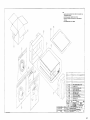
MRI
3103-1
Omega 1400 series
Non-Invasive Blood Pressure Monitors
,
4
~=:J
Invivo
Research
Incorporated
Precision Biomedicalln.struments
Invivo Research Incorporated -12601 Research Parkway - Orlando, Florida 32826
··Model.14.00·.MRI
SelViceMa.nual
MANUAL BY:
Uoyd L Shoemaker
Technical Publications
EDITED BY:
Tom W. Foshee
Director of Quality Assurance
IRI PN# 9506M
Release _2, 7/93
ECN#3584
©1993
INVIVO
RESEARCH
.
.......
....
'
."~=·~:JlNt:OR1>oRATED
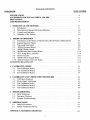
TABLE OF CONTENTS
PARAGRAPH
PAGE NUMBER
SPECIFICATIONS .......... . ..............................................
ACCESSORIES FOR THE 3103 OMEGA 1400 MRI ...............................
PRECA UTIONS ............................................................
USER RESPONSmILITY ....... ............................................
III
IV
V
VI
1. OPERATION OF THE MONITOR. . . . . . . .. ................................ 1-1
1.1
1.2
1.3
1.4
Introduction. . . . . . . . . . . . . . . . . . . . . . . . . . . . . . . . . . . . . . . . . . . . . . . . . . . . . ..
Description of Omega 1400 Series Monitors .............................
Controls and Indicators . . . . . . . . . . . . . . . . . . . . . . . . . . . . . . . . . . . . . . . . . . . . ..
Operation of the Monitor ............................................
I-I
1-2
1-3
1-9
2. THEORY OF OPERATION ........ , ..... , ..... , ........ , ...... " ..... ,... 2-1
2.1
Introduction to the Theory of Oscillometric Blood Pressure Measurement , . . . ..
2.2 Logical Sequence Theory .... . ............... ,......................
2.3
FWlctional Description ... ,............... ...... ...................
2.4 AB08A Processor Board . . . . . . . . . . . . . . . . . . . . . . . . . . . . . . . . . . . . . . . . . . . ..
2.5
AB08C Display Board. . . . . . . . . . . . . . . . . . . . . . . . . . . . . . . . . . . . . . . . . . . . . ..
2.6 AB08D Rear Panel Control Board ............. . ......................
2.7 AP2I Pump-Drive Assembly .........................................
2.8
Power Circuitry ..................... " '"
.......................
2.9 AB08F2 Power Supply Board. . . . . . . . . . . .. ...........................
2.10 AB20A Protocol Converter Board ........... ..,......................
SUGGESTED READING LIST .............................. , ................
2-1
2-3
2-6
2-7
2-9
2-10
2-10
2-11
2-11
2-11
2-13
3. CALmRATION MODES ................................................. 3-1
3.1
3.2
3.3
Test-Calibration Mode 1 ............................................. 3-1
Test-Calibration Mode 2
3-2
Test-Calibration Mode 3
3-3
4. CALmRATION AND VERIFICATION PROCEDURES ........................ 4-1
4.1
4.2
4.3
4.4
4.5
Calibration Checkout ................................ , . . . . . . . . . . . . .
Power Supply Calibration . . . . . . . . . . . . . . . . . . . . . . . . . . . . . . . . . . . . . . . . . . ..
. Test-Calibration Mode 1 .................. ,.... ................. ...
Test-Calibration Mode 2
Test-Calibration Mode 3
4-1
4-1
4-2
4-4
4-9
5. TROUBLESHOOTING .....
5-1
5.1
Initial Inspection ................................. . ............... . 5-1
5.2 Operation Checkout. . . . . . . . . . . . . . . . . . . . . . . . . . . . . . .. ........... . .. . 5-1
5.3
Systems Troubleshooting .......... .................. . ............ . 5-3
6. ORDERING PARTS ........................... ......... ..............
6.1
6.2
6-1
Ordering Procedure . . . . . . . . . . . . . . . . . . . . . . . . . . . . . . . . . . . . . . . . . . . . . . . .. 6-1
Factory Authorized Service. . . . . . . . . . . . . . . . . .. ....................... 6-1
APPENDIX A: REFERENCE DRAWINGS ...................................... A-I
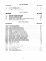
LIST OF FIGURES
Figure Number
Page Number
I-IOmega 1400MRI Front Panel. . . . . . . . . . . . . . . . . . . . . . . . . . . . . . .. ..... .. 1-4
1-2
Omega 1400MRI Back Panel ......................................... 1-8
2-1
Oscillometric Measurement Technique . . . . . . . . . . . . . . . . . . . . . . . . . . . . . . . . .. 2-1
LIST OF TABLES
Table Number
1-1
1-2
4-1
5-1
5-2
Page Number
High and Low Alarm Pre-Set Limits ........................... .......
High and Low Alarm Limit Ranges ....................................
Systolic Pressures and Tolerances . . . . . . . . . . . . . . . . . . . . . . . . .. .... ......
P;obable Causes of Monitor Being Unable to Determine Pressures ............
Board Level Troubleshooting Procedures . . . . . . . . . . . . . . . . . . . . . . . . . . . . . . ..
1-12
1-14
4-4
5-2
5-6
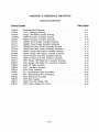
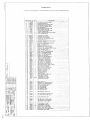
LIST OF DRAWINGS
Drawing Number
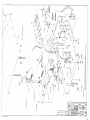
97D149
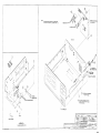
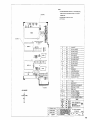
97D276
97D270
194D502
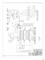
85D067
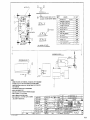
94C397
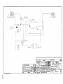
85C127
94C212
85C064
94D170
85D060
94C393
85D115
94C217
85B070
59B094
94B384
94B216
59D051
57C009
94B106
94B073
94B237
94B135
Page Number
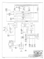
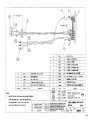
Functional Block Diagram .. .. . ......... , ........... ,. ...... .,..
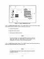
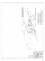
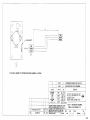
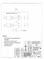
3103-1 Packaging Drawing ............................ , ...... , . .. ..
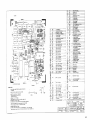
Omega 1400 MRI Assembly Drawing .................................
AB08A Processor Assembly Drawing .................................
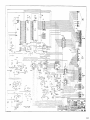
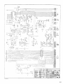
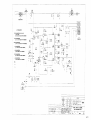
AB08A Processor Assembly Schematic . . . . . . . . . . . . . . . . . . . . . . . . . . . . . . ..
AB08F2 Power Supply Assembly Drawing . . . . . . . . . . . . . . . . . . . . . . . . . . . ..
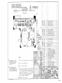
AB08F2 Power Supply Assembly Schematic ...................... , . . . ..
AB08D Rear Panel Control Assembly Drawing. . . . . . . . . . . . . . . . . . . . . . . . ..
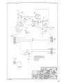
AB08D Rear Panel Control Assembly Schematic .......................
AB08C Omega 1400 Display Assembly Drawing..... . .. . .. . ......
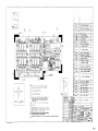
AB08C Omega 1400 Display Assembly Schematic ....... , ... , ...........
AB20A Protocol Converter Assembly Drawing ..........................
AB20A Protocol Converter Assembly Schematic ........................
AP21 Omega 1400 Pump Drive Assembly Drawing .....................
AP21 Omega 1400 Pump Drive Assembly Schematic .....................
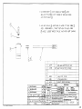
AS93 1/0 Cable Assembly ..........................................
AS37 Transducer Assembly .........................................
AP20 Valve Assembly ..............................................
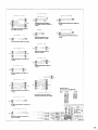
AC-- Miscellaneous Cable Assemblies . . . . . . . . . . . . . . . . . . . . . . . . . . . .. ..
AW-- Miscellaneous Wire Assemblies .................................
AP15 Patient Port Assembly ........... , .. , . . . . . . . . . . . . .. ......... .
AP07 Hose Adapter
, ................. , ... , , , , ' ...............
AM07 Prom Set, Omega 1400 ................... , ... , ...............
AP07A Hose Adapter (No Valve) ........ ' ... , .... , .. , ................
11
A-2
A-3
A-4
A-5
A-6
A-7
A-8
A-9
A-IO
A-ll
A-I2
A-13
A-14
A-15
A-16
A-17
A-18
A-19
A-20
A-21
A-22
A-23
A-24
A-25
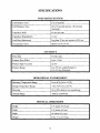
SPECIFICATIONS
PNEUMATICS SYSTEM
Cuff Inflation Time
3 to 20 seconds
Cuff Deflation Time
20 to 50 seconds typical; 180 seconds
maximum
Transducer Drift
±3 torr per year
torr
Transducer Repeatability
Leak Rate (Maximum)
Less than 20 torr per minute at 200 torr
Overpressure Valve
Opens at 270 ±14 torr
ACCURACY
Pulse Rate
2% full scale
Pressure Zero Offset
6 torr ±5 torr
Pressure Span Accuracy
±2 torr
Pressure Range
o to 255 torr (AdultlPediatric)
o to 210 torr (Neonate)
OPERATIONAL ENVIRONMENT
Operating Temperature Range
10 to 44°C (50 to 110°F)
Storage Temperature Range
-18 to 52°C (0 to 125°F)
Humidity
10 to 90% relative, non-condensing
Altitude Range
-1000 to 10,000 feet
PHYSICAL DIMENSIONS
Height
4.25 inches (10.8 cm)
Width
9.45 inches (24 cm)
Depth
10 inches (25.4 cm)
Weight
61bs, 15 oz (3.15 kg)
III
ACCESSORIES FOR THE 3103 OMEGA 1400 MRI
DESCRIPTION
PRODUcr CODE
Omegacart, MRI .............................................. ......... 9002M
Handbulb Assembly. .......................... . ......................... 9001
Twin-Lumen Adult Air Hose, MRI .. . . . . . . . . . . . . . . . . . . . . . . . . . . . . . . . . . . . . . . .. 901 OM
Single-Lumen Neonatal Air Hose, MRI ..................................... 9010NM
Operations Manual. . . . .. .......... . ................................... 9505M
Service Manual ......................................................... 9506M
REUSABLE BLOOD PRESSURE CUFFS
Adult Cuff, MRI ........................................................
Adult Cuff, Large Arm, MRI . . . . . . . . . . .. ..................................
Pediatric Cuff, MRI . . . . . . . . . . . . . . . . . . . . . . . . . . . . . . . . . . . . . . . . . . . . . .. ......
Adult Cuff, Thigh, MRI . . . . . . . . . . . . . . . . . . . . . . . . . . . . . . . . . . . . . . . . . . . . . . . . . ..
9070M
9080M
9060M
9090M
DISPOSABLE NEONATAL BLOOD PRESSURE CUFFS
A complete selection of disposable neonatal blood pressure cuffs is available with either hookand-loop or tape c1 ures. Cuffs are of soft, white vinyl. Each cuff is individually packaged in its
own peel pouch, aa.... is ready for use. Gas sterilizable. Luer fittings.
FOR SPECIFICATIONS AND PRICING OF ALL OMEGA
1400 ACCESSORIES, CONTACT INVIVO ClJSTOMER
SERVICES TOLL FREE: 800-331-3220.
IV
PRECAUTIONS
The Omega 1400 (Model 3101-1) is especially modified for MRI use and has been constructed with
minimal ferrous material. However, small amounts of magnetically attractable materials have
remained (i.e.: screws and pump motor), and this unit must be kept at least five feet from the bore.
It is recommended that the unit be strapped or restrained to some permanent structure, or mounted
on an Invivo MRI (Aluminum) cart and kept greater than five feet from magnet bore. NEVER
PLACE THIS DEVICE ON mE PATIENT TABLE OR INTO mE BORE.
When using this instrument to monitor blood pressure, remember that the patient's blood pressure
readings are not continuous, but are updated each time a blood pressure measurement is taken. Set
the INTERVAL from the Omni-Trak's NIBP menu to shorter time periods for more frequent
updating of the patient's blood pressure.
Monitor is not intended for use in the presence of flammable anesthetics. An explosion hazard
exists.
Do not attach the cuff to a limb being used for infusion. Cuff inflation can block infusion, possibly
causing harm to the patient.
Never immerse the unit in any fluid or attempt to clean it with liquid cleaning agents. An electrical
hazard exists.
Do not use a monitor that has failed in any part of the calibration or leak tests. The values displayed
by such a unit are inaccurate.
No repair should be undertaken or attempted by anyone not having a thorough understanding of the
repair of automatic blood pressure monitors.
USER RESPONSmILITY
This product will perform in conformity with the description thereof contained in this service manual
and accompanying labels and/or inserts, when assembled, operated, maintained and repaired in
accordance with the instructions provided. This product must be checked and calibrated
periodically. A defective product should not be used. Parts that are broken, missing, plainly worn,
distorted or contaminated should be replaced immediately. Should such repair or replacement
become necessary, Invivo Research, Incorporated (IRI) recommends that a telephone call (toll free:
(800) 331 - 3220) or written request for service be made to the nearest factory service center. This
product or any of its parts should not be repaired other than in accordance with written instructions
provided by IRI, or altered without written approval ofIRI. The user of the product shall have the
sole responsibility for any malfunction which results from improper use, faulty maintenance,
improper repair, damage or alteration by anyone other than Invivo Research or Invivo Research
authorized service personnel.
v
SECTION I
OPERATION OF THE MONITOR
This section provides a brief overview of Oscillometric Monitors, provides
information on the controls and indicators of the monitor and provides
instructions on the operation of the monitor.
1.
OPERATION OF mE MONITOR
1.1
Introduction
By deriving it's power from the MRI monitoring system, or from the HE28A AC adapter, the 3101
Omega 1400 MRI can function as a stand alone device. When in System configuration, the monitor
may be started or stopped either by it's front panel controls or from the Omni-Trak's NIBP menu
controls. Users in the magnet room and control room should coordinate their control of the Omega
1400 when in System configuration.
1.1.1
Brief Theory of Operation. The Omega 1400 series monitors make blood pressure
measurements based on the Oscillometric principle. Oscillometric Monitors use an inflatable
occlusive cuff which is also used in the manual auscultatory technique; however, rather than
monitoring undependable Korotkoffsounds, Oscillometric Monitors detect and measure oscillations
induced in the cuff by the movement of the arterial wall.
Steps a through d describe the process of Oscillometric Measurement:
a. As the occlusive cuff is inflated to a suprasystolic pressure the artery is occluded so that
no blood passes through.
b. As cuff pressure is reduced to just below the systolic pressure, the force of the height
of the systolic pressure wave forces the occluded artery open, blood spurts through the
artery and the amplitude of the oscillations increase sharply. This is known as systolic
pressure.
c. With further reduction in cuff pressure: the artery opens for a longer time during each
cardiac cycle, which causes increasingly larger oscillations in the cuff pressure until
they reach a point of maximum oscillation amplitude. This point of maximum
oscillations has been well-demonstrated to be Mean Arterial Pressure (see Geddes, L. A.,
et ai, "The Meaning of the Point of Maximum Oscillations in Cuff Pressure in the
Indirect Measurement of Blood Pressure").
d. With continued cuff-pressure reduction, the underlying artery is open throughout the
cardiac cycle, and the arterial-wall movement is less. The cuff pressure oscillations
begin to decrease in amplitude until they become uniform. The point at which the
amplitudes become uniform is diastolic pressure.
1-1
1.1.2
Simplified Theory of Operation. In simple terms, oscillometric monitors utilize a pressure
transducer which is connected to the cuff via a hose. The transducer transforms the oscillations
induced into the cuff pressure into electrical currents. Under control of a microprocessor and
software algorithms, the electrical current can then be measured and correlated with the cuffpressure
to determine arterial blood pressure.
1.2
Description of Omega 1400 Series Monitor.;
The Omega 1400 Series AdultlNeonate Monitors are non-invasive blood pressure monitors which
automatically measure and display a patient's systolic, diastolic and mean arterial blood pressures
at preset intervals. They may also display information upon operator demand. Besides blood
pressure information, the average pulse rate is also determined and displayed on the front panel with
the blood pressure values.
1.2.1
ADULTINEONATE Selector. The ADULTINEONATE selector allows the monitor to
determine pressures on a wide range of patients. Several operational parameters (including cuff
inflation pressure) are varied depending on the setting of the ADULTINEONATE selector which
allows the appropriate operation for each patient selected.
1.2.2
AdultlNeonate Safeguards. Two automatic safeguards prevent inadvertent switching of
the ADULTINEONATE selector, and improper mode and cuff size matching. First, changing the
setting of the ADULTINEONATE selector while power is ON will cause the monitor to lock up and
will sound the ALARM. Second, the monitor senses the size of the cuff being used and will
ALARM if a neonatal cuff is used in the Adult mode, or if an adult cuff is used in the Neonatal
mode.
1.2.3
International Standard Labeling. Omega 1400 monitors are labeled with "torr", the
international standard of pressure measurement, for blood pressure values. One torr equals one
mmHg (millimeter of mercury).
1.2.4
Alarm Limits. Alarm limits for SYSTOLIC, DIASTOLIC and MEAN arterial pressures
as well as pulse rate are set to predetermined values upon initial power up. The Alarm limits may
be changed or disabled by the operator at any time by use of the Alarms SELECT, Alarms ON/OFF,
HI SET and LO SET controls. An audible alarm tone and visual signal are triggered whenever a
blood pressure parameter alarm limit is violated.
1.2.5
Alarm Violation Routine. Once violated, the Alarm sounds for 16 seconds, after which
another blood pressure measurement is taken. If the Alarm limits are violated during the new
reading, the Alarm tone sounds for another 16 seconds. The monitor will alternate between pressure
reading cycles and Alarms until the violated parameter returns within limits, the HOLD control is
pressed or the Alarms are inactivated with the Alarms ON/OFF control.
1.2.6
Blood Pressure Reading Intervals. A blood pressure reading may be taken at automatic
intervals, or the operator can take manual control of the monitor's determination cycles at any time
using the START or HOLD controls. If the Digital Manometer mode is selected, the cuff can be
inflated with an optional hand bulb, and blood pressure measurements made with the auscultatory
technique.
1-2
,
'
: ":':'-': -';
;,:-:,::=::::::,::-:,":::::'
WARNING . · · . ·
,
','
-
,"
.
·>'Jhe • patie~ttsbloodPressuredett;rmbl~tionsare~pdate~ • eac:h.ume • ·a •. j)lood • pressure .
• JIleasurementistaken and are not continuous~Whe~usil)~1hisinstrumentto Itlonitor critical
. .••. conditionsset1.belNTERV'AL display to shorterperiodsformore fre9uent npdatingof the
blood·.pressure··determinatloris.
1.2.7
Normal Operation. During normal operation, the displayed blood pressures and pulse rate
indi cate the patient's condition at the time of the last measurement. Depending on the setting in the
INTERVAL display, as long as 99 minutes may elapse between blood pressure measurement cycles;during this time, the patient's condition may change. Correspondingly, the alarms reflect only the
patient's condition during the last blood pressure measurement, and not changes that may occur
between measurements.
1.3
Controls and Indicators
1.3.1
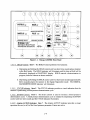
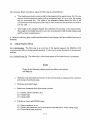
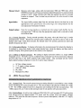
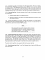
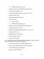
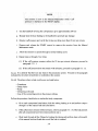
FrontPanel. (See Figure 1-1) There are five displays, seven indicator lights and six soft
touch controls located on the front panel. The following is a brief discription of every control and
indicator located on the front panel:
NOTE
>Omegamonit()rs use tile.· internationalunit.Clf·.press.uremeasurement,
"torr."One. torr equalsbn~.·ll1pllIg('Eillirneterbf mercury);
1.3.1.1 SYSTOLIC torr Display. Item 1. The SYSTOLIC torr display provides a visual indication
of the last systolic blood pressure of the patient.
1.3.1.2
MEAN torr Display. Item 2. The MEAN torr display performs three functions:
a. The MEAN torr display indicates the last measured arterial pressure of the patient.
b. During a blood pressure determination cycle, the MEAN torr display indicates the
actual cuff pressure.
c. While in the Digital Manometer mode, the MEAN torr display indicates the actual cuff
pressure.
1.3.1.3 HOLD Indicator. Item 3. The HOLD indicator provides a visual indication that the
monitor is in the Hold mode.
1-3
SYSTOLIC
IIIrr
[
DIASTOLIC
1Drr
Non-In'\cisive Blood Pressure
Invlvo R.lsean:h Laboratories Inc.
21
Figure I-I. Omega 1400MRI Front Panel
1.3.1.4
HOLD Control. Item 4. The HOLD Control performs two functions:
a. Depressing and holding the HOLD control until one short tone sounds places monitor
in the Hold mode. The HOLD indicator will illuminate, and the time in Hold will be
alternately displayed in DIASTOLIC display. HOLD cancels a determination in
progress, and also silences an alarm condition.
b. Depressing and holding the HOLD control until two short tones sound (approximately
three seconds) places the monitor in the Digital Manometer mode. The DIGITAL
MANOMETER MODE indicator will illuminate.
1.3.1.5 CYCLE Indicator. Item 5. The CYCLE indicator provides a visual indication that the
monitor is performing a blood pressure determination cycle.
1.3.1.6 START Control. Item 6. The Start control is used to initiate a blood pressure
determination cycle. A blood pressure determination cycle is initiated by depressing the START
control untit one tone sounds and the CYCLE indicator illuminates.
1.3.1.7 Alarms ACTIVE Indicator. Item 7. The Alarms ACTIVE indicator provides a visual
operation the one (or all) of the blood pressure parameter Alarms are active.
1-4
NOTE
Ifconnectedto tlleSystem,alarmsandintervalsarecontrolledby. the
·.Onmi-Trakjn·the control room viatheAlaImsmenu,.·NIBRs~ction.
1.3.1.8
Alarms ON/OFF ControL Item 8. The Alarms ON/OFF control is used for the following:
a. Tum all alarms OFF or ON at one time.
b. To tum off the Alarms for a particular parameter (while in the Select mode).
c. To silence the Alarm.
1.3.1.9 Alarms SELECT Control. Item 9. The Alarms SELECT control is used to putthe monitor
in the Select mode. The following settings may be made from the Select mode:
a. The blood pressure parameter may be viewed andlor adjusted.
b. The blood pressure Alarms may be turned ON or OFF.
Depressing the Alarms SELECT control will display each blood pressure parameter
display on the front panel in a counterclockwise fashion. The first depression displays
MEAN, the second displays SYSTOLIC, the third display DIASTOLIC and the fourth
display PULSE. The selected display will alternate between the High Alarm limit and the
Low Alarm limit.
As a safety feature, if no controls are pressed within approximately ten seconds, the
monitor will exit the Select mode.
1.3.1.10 ALARMS Indicator. Item 10. The ALARMS indicator provides a visual indication that
the Alarm limit has been violated.
1.3.1.11 HI SET Control. Item 11. The HI SET control performs three functions:
a. While in the Alarms Select mode: momentarily depressing the HI SET control will
cause the High Alarm limit for the selected parameter to "freeze" in the display for
approximately one second.
b. While in the Alarms Select mode: depressing and holding the HI SET control will
increase the High Alarm limit of the selected parameter by increments of five torr.
Once the upper limit of the High Alarm is reached, the display will "roll over" to the
lower limit and continue to increase in five torr increments.
c. In all other modes: depressing the HI SET control will increment the Interval. Pressing
once and releasing will increment the time by one minute while pressing and holding
will cause the time to increment by ten minute intervals.
1-5
1. 3. L 12 LO SET Control. Item 12. The LO SET control performs three functions:
a. While in the Alarms Select mode: momentarily depressing the LO SET control will
cause the Low Alarm limit for the selected parameter to "freeze" in the display for
approximately one second.
b. While in the Alarms Select mode: depressing and holding the LO SET control will
increase the Low Alarm limit of the selected parameter by increments offive torr. Once
the upper limit of the Low Alarm is reached, the display will "roll over" to the higher
limit and continue to increase in five torr increments.
c. In all other modes: depressing the LO SET control will decrement the Interval. Pressing
once and releasing will decrement the time by one minute while pressing and holding
will cause the time to decrement by ten minute intervals.
1.3.1.13 INfERVAL Display. Item 13. The INTERVAL display is not active on the Omega
1400:MRI. Intervals are controlled by Omni-Trak.
1.3.1.14 PRINTER ON Indicator. Item 14. The PRINTER ON indicator is not active on the Omega
1400]1..00. The 1400:MRI is not equipped with an internal printer.
1.3.1.15 DIGITAL MANOMETER MODE Indicator. Item 15. The DIGITAL MANOMETER
MODE indicator performs two functions:
a. If flashing, the DIGITAL MANOMETER MODE indicator provides a visual indication
that the monitor is in the Digital Manometer Mode.
b. If steadily illuminated, the DIGITAL MANOMETER MODE indicator provides a
visual indication that the monitor is on internal battery operation (if so equipped).
1.3.1.16 CUFF Ports. Item 16. The two CUFF ports provide for the connection of the external air
hose (a twin-lumen for adult use, or single-lumen for neonate use). Either connection on the hose
may be used on either port. Screw air hose connections snugly into place for an air tight fit.
1.3.1.17 ADULTINEONATE Indicators. Item 17. The ADULTINEONATE indicators provide a
visual indication of the setting of the ADULTINEONATE selector.
1.3.1.18 POWER Switch. Item 18. The POWER switch is a two position switch. To tum the
monitor ON, depress the right side; In tum the Tt']onitor OFF, depress the left side. When power is
applied: all LED indicators will illummate, a ''':',ef tone will sound, the INTERVAL display will
indicate "88" and the SYSTOLIC, DIASTOLIC, MEAN and PULSE displays will indicate "188"
then "288."
1.3.1.19 ADULTINEONATE Selector. Item 19. The ADULTINEONATE selector is a two
position switch which allows the operator to select the operation appropriate to the patient. This
selector controls the following:
a. The initial cuff inflation pressure of the pump.
b. The preset Alarm limits.
1-6
c. The maximum and minimum high and low Alarm limit ranges.
d. The software algorithm for adult or neonate operation.
As a safety feature, the monitor will lock up and the Alarm will sound if this setting is
changed while the unit is ON. If this occurs, reset the monitor for proper operation by
turning the monitor OFF, placing the ADULT /NEONATE selector in the desired position
and turning the monitor ON.
1.3.1.20 PULSE bpm Display. Item 20. The PULSE bpm display performs two functions:
a. The PULSE bpm display indicates the average measured pulse rate of the patient (in
beats per minute) during the last blood pressure determination cycle.
b. In the Automatic Interval mode, the PULSE bpm display alternately indicates elapsed
time since the last blood pressure determination cycle.
1.3 .1.21 DIASTOLIC torr Display. Item 21. The DIASTOLIC torr display performs two functions:
a. The DIASTOLIC torr display indicates the last measured diastolic blood pressure of the
patient.
b. When the monitor is in the Hold mode, the DIASTOLIC torr display will alternate
between the last measured diastolic blood pressure of the patient and the elapsed time
in the Hold mode.
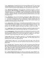
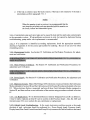
1.3.2
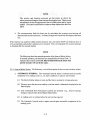
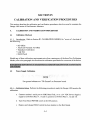
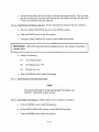
Back PaneL (See Figure 1-2) The back panel consists of a digital manometer connection,
one paper feed control, one 110 port, CautionslWamings, the Alarm Volume control and the Alarm
Tone control. The following is a discription of the controls and notes located on the back panel:
1.3.2.1 DIGITAL MANOMETER Port. Item 1. The DIGITAL MANOMETER Port is a screw
connector which provides for use of a hand bulb when the Omega 1400 is in the Digital Manometer
mode.
1.3.2.2
PAPER FEED Control. Item 2. This control is not used.
1.3.2.3 I/O Port. Item 3. The I/O Port provides for the connection of Omni-Trak MRI System
Power and serial communication interface.
1.3.2.4 CAUTIONSIWARNINGS. Item 4. Text which alerts the operator to potential hazards.
Invivo strongly recommends that every operator become througbly familierwith these Cautions and
Warnings, as well as the Cautions and Warning section in the front of this manual, before operating
the 1400 MRI Non-Invasive Blood Pressure Monitor.
1-7
CAImOII; Elac1rical SII01:k Haanl;
Do 110\ remove cover. Refer _rvleInllO qualirllld sanica plll'llDllUl.
WARNING: Far CoII1inued prDIulion
against Fire alld Sb.ct Haanls.,.. --1-----1
plac. only wi1b Allie Iypa of fuIe .
DAtl6ER: PllSsibie flIplo$ion Hazanl
" used In 111. presence of Flammable
Aneslbelic&.
DANGER-RISQUE D'EXPLQSION, liE PAS
EMPLOYER Ell PRESENCE
0'ANESTHESIQUES INFlANNABlES.
PATENT PENDING
®
Figure 1-2. Omega 1400MRI Back Panel
1.3.2.5 ALARM TONE ControL Item 5. The ALARM TONE Control is a three position toggle
switch which permits the operator to select the following Alarm tones:
a. Low pitch (Top position).
b. High pitch (Center position).
c. Alternating pitch (Bottom position).
-
-
.
.
..
~
Toavoidconfusion:itis .recqmlllendedthru-the·.bperator sele~rthe
tone whiCh 'Will alt8W< aIa.rmsGoti this monitOr to be
. distinguishedfromalatms.. orititbermonitbrll1geqttipl11ent .... . ..
alarm
1.3.2.6 ALARM Volume ControL Item 6. The ALARM Volume Control allows the operator to
control the volume (amplitude) of the audible alarm tone.
:.'
NO'I'E·· .
.·•.
is~,~&r~feafure,i,liealai!l' 'Y"1u:~. m~~' b"lo~red;bp"cartIjot be
. ·CompIetelyt\ll1le4 off.
1-8
1.4
Opera1ion of the Monitor
:,<
':. -":::-.
,,' "
,
,-, _ ... ".
'"
.·.·······Nev~r.•. •.use • •• •iliiS· ". IIlotlitor· .'ih·. tile ..•preS~ce•.·.·.of.•··'fllIllm~~l·~• • ·tules~etic§:.
HAZAR.DEXISTS.
. ' .. ,
1.4.1
Cuff Preparation. The patient should remain calm and motionless while the monitor is
being used. If the patient is overactive, more time is required to take an accurate reading.
1.4.1.1 Cuff Selection. The cuff is selected and positioned as it would be for an auscultatory blood
pressure determination, and the guidelines of the American Heart Association in their publication
Recommendationsjor Human Blood Pressure Determination by Sphygmomanometers should be
followed. The bladder width of the cuff should be 40% of the circumference of the limb. For a
correct fit on adult and pediatric non-disposable cuffs, the Index line on the end of the cuff must fall
between the two Range lines prInted on the inside of the cuff. For correct fit on neonatal disposable
cuffs, choose the size whose stated circumference range fits the circumference of the limb of the
neonate.
,
"
-
--
.
. .. Do notattachihecufftoaIimbbeing used fo rinfuSi on. Tuffintllition canblocktheinfusion
c~~irig~sSi~le>1tadn~opati¢nt . .
.'... ...... ..' .
'.' . . ..... .
.
1.4.1.2 Cuff Positioning. The cuff should be wrapped firmly (not snug) around the arm of the
patient and positioned as close to heart level as possible. If the cuff is not at heart level, add 1.8 torr
to the displayed readings for each inch that the center of the cuffis located above the patient's heart
level; subtract 1.8 torr from the displayed readings for each inch that the cuff is located below the
patient's heart level
1.4.1.3 Cuff Connection. Select the proper hose (twin-lumen for adults, single-lumen for
neonates), and attach hose to cuff. Route the hose from the cuff to the monitor so it does not kink,
tangle, or limit access to the patient.
1-9
NOTE
··;iifi~~ill~t;;if~ii'I~~~I~~~r'\
1.4.2
Monitor Operation. Operation of the monitor is as follows:
1.4.2.1 Power Up Routine. Pressing the POWER switch to the right to tum the monitor ON. Upon
power up the monitor performs a routine which allows the operator to verify correct functioning of
the Alarm, displays and indicators. The power up routine is as follows:
a. ADULT indicator illuminates.
b. ADULT indicator goes out, NEONATE and PRINTER ON indicators illuminate.
c. The four blood pressure displays indicate "188" for approximately two seconds, then
indicate "288", two Alarm Tones sound while ALARMS indicator flashes, and all
indicators (except NEONATE) are illuminated.
d. All indicators (except ADULT) go out.
e. ADULT or NEONATE (as selected) and ACTIVE indicators are illuminated.
f. HOLD, ACTIVE and ADULT or NEOr-.· :\TE (as selected) indicators are illuminated.
g. After approximately three seconds: four touch tones sound which indicates that control
has been transferred to the Omni-Trak.
h. HOLD and ADULT or NEONATE (as selected) indicators are illuminated.
1.4.2.2 Operator Override. The operator may override automatic operation of the monitor at any
time by use of the START or HOLD controls.
1.4.2.3 Operator Initiation of Blood Pressure Determination Cycle. The operator may initiate a
blood pressure determination cycle by depressing the START controL At the completion of the
blood pressure determination cycle, the monitor will enter the Hold mode and return control to the
Omni-Trak.
1.4.3
Automatic Interval. See "Omni-BUS" section of the Omni-Trak Operator manual. Select
AutolInterval or Manual mode from the NIBP menu of the Omni-Trak.
1.4.4
Alarms. On initial power-up, the alarms on all four blood pressure parameters (systolic,
diastolic and mean arterial pressures, and pulse rate) are automatically turned off by the Omni -Trak.
1-10
(See Omni-BUS) section of the Omni-Trak operations manual) The limits are set on the Omni-Trak
Alarms chart display menu. This monitor does have "stand alone" capability; while operating as a
stand alone monitor, control of the Alarm Parameters is accomplished as described in paragraphs
1.4.4.1 through 1.4.4.7.
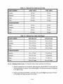
1.4.4.1 Preset Alarm Limits at the Omega 1400. Should alarm monitoring be desired at the Omega
1400, press the Alarms ON/OFF control on the front paneL The ACTIVE indicator will illuminate
and Alarms on all four blood pressure parameters (systolic, diastolic and mean arterial pressures,
and pulse rate) are turned ON. The High and Low Alarm limit pre-sets are listed in Table 1-1.
1.4.4.2 Turning Alarms OFF On Individual Parameters. To turn off the alarms on individual
parameters, perform the following:
a. Select the parameter to be turned OFF by depressing the Alarms SELECT control until
the desired parameter is selected. The selected display will alternate between the High
and Low Alarm limits.
As . a .safety .featUie~ if. no controls •areptessedfo(apptoximately ten
seConds while in theS~lect m()de, the monitor will eXitautomatlcally.
b. Depress the Alarms ON/OFF control until a short tone sounds.
c. Release the Alarms ON/OFF control.
d. The display will begin to alternate between "00" and "255" indicating that the alarm for
that parameter is OFF.
·NOl'E
TheAlarm~A.CTI~jn.di¢~tor~llrefuaini11uminatedaslong
·w>any oriealarmisac~Y~:· . ..
. .
.
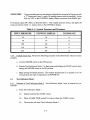
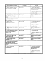
1.4.4.3 Range of High and Low Alarm Limits. The High and Low Alarm limits for each blood
pressure parameter can be set within a range. The ranges are listed in Table 1-2.
1-11
Table 1-1: High and Low Alann Pre-Set Limits
HIGH LIMIT
LOW LIMIT
Systolic
190 torr
65 torr
Diastolic
125 torr
40 torr
Mean
135 torr
55 torr
Pulse
160 bpm
45 bpm
Systolic
130 torr
40 torr
Diastolic
80 torr
25 torr
Mean
100 torr
30 torr
Pulse
210 bpm
60 bpm
Table 1-2: High and Low Alann Limit Ranges
.
...
.
....
·ADULT:MODE·.·• • .·•·•.
HIGH RANGE
LOW RANGE
Systolic
80 to 235 torr
60 to 135 torr
Diastolic
30 to 175 torr
30 to 95 torr
Mean
75 to 195 torr
40 to 120 torr
Pulse
50 to 195 bpm
40 to 95 bpm
Systolic
65 to 175 torr
35 to 95 torr
Diastolic
40 to 115 torr
15 to 80 torr
Mean
50 to 145 torr
·15 to 85 torr
Pulse
100 to 215 bpm
55 to 115 bpm
.
.::
.
...
. ...
. . . ..
:.. : .. :.
...•. : .• : •. : . •:.....: . . . .< : :.• : .•
NEONA.TEMODE
1.4.4.4
Checking Alarm Limits. To check the Alarm limits, perform the following:
a. Select the parameter to be checked by depressing the Alarms SELECT control until the
desired parameter is selected. The selected display will alternate between the High and
Low Alarm limits.
b. Depress and release the ill SET control (this will cause the High Alarm limit to "freeze"
in the display for approximately one second).
1-12
c. Depress and release the LO SET control (this will cause the Low Alarm limit to
"freeze" in the display for approximately one second).
1.4.4.5
Changing Alarm Limits. To change the Alarm limits, perform the following:
a. Select the parameter to be changed by depressing the Alarms SELECT control until the
desired parameter is selected. The selected display will alternate between the High and
Low Alarm limits.
b. To change the High Alarm limit, depress the HI SET control and the limit will increase
in five torr increments. When the Alarm limit reaches the highest range, the display
will "roll over" to the lowest range and continue to increase by five torr increments.
c. To change the Low Alarm limit, depress the LO SET control and the limit will increase
in five torr increments. When the Alarm limit reaches the highest range, the display
will "rol1 over" to the lowest range and continue to increase by five torr increments.
1.4.4.6 Alarm Violations. When an alarm limit is violated, the alarm tone sounds for 16 seconds,
the red ALARMS indicator flashes, and the display(s) of the violated alarm(s) flash on and off.
After 16 seconds, the monitor begins a new pressure determination cycle. The unit continues to
cycle between alarms and pressure measurements as long as alarm limits are violated.
To silence an alarm: Place the monitor in Hold, or briefly depress the Alarms ON/OFF control; four
short tones will sound, each blood pressure parameter display will flash briefly, and the Alarms
ACTIVE indicator will extinguish.
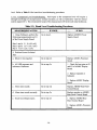
1.4.4.7 Other Factors That Can Trigger An Alarm. In addition to violating an active alarm limit
on a blood pressure parameter, there are other factors which will cause the monitor to alarm. The
Omega 1400 has the following built-in safety features which will cause the monitor to alarm,
regardless of the settings of the alarm limits or the Alarms ON/OFF control:
a. A pressure reading takes more than 2.5 minutes.
b. The cuff inflation pump runs longer than 22 seconds in the Adult mode, or longer than
six seconds in the Neonate mode.
c. Cuff pressure remains at one level for more than 30 seconds during a determination
cycle.
d. A hardware (electronic or electrical) malfunction stops the microprocessor for three
minutes.
e. A MAP of less than ten torr.
f. A pulse rate of "0".
1-13
CAUTION
Whenin·theDigital •. MaJ1oIlleterJl1ode,theoper~to~jSi~.contr()lof1:he.puffpressure ..
•Whenfillished,completely·. eXhatlSl the cuff pressUre•. iliell dose the lland bulb bleed
vaJve.• ·••··•·•· · ·
.....
.
.... ...
1.4.5
Digital Manometer Mode. If the patient shows signs of arrhythmia, the automatic circuitry
within the monitor may have difficulty determining blood pressures and pulse rates. This is usually
evidenced by long blood pressure determination cycles, or by an alarm caused by pressure readings
which take longer than three minutes. In such instances, or whenever desired, the operator may
configure the monitor for manual (auscultatory) blood pressure measurements. this may be done
without changing the cuff or front-panel how connections.
To configure the monitor for manual blood pressure measurements, perform the following:
a. Remove the red protective cover from the DIGITAL MANOMETER port on the back
panel of the monitor.
b. Connect the accessory hand bulb by screwing the hand bulb hose connector firmly for
an air tight fit.
..
:-. ...... ;:.,::
~
'
..
'
> ••• )Vhelltheharldbulhis
. ..... .
::
:: - . '.'::
-: .
:: :":':,:
'-
:.
.'.
:': .:,:.
.'
. .: :.
nbtconnectedrtbe~r()f~Ctivered. cover •
. >s1J.ouldl)ereplacedntl fuepcfrt tQ • keep
o#tdqSt:@ddirtY·
c. Depress and hold the HOLD control until two short tones sound. The DIGITAL
MANOMETER indicator will begin to flash, indicating that the monitor is in the Digital
Manometer mode.
d. The MEAN display is now a digital manometer, and will read actual cuff pressure. The
operator now has 60 seconds to perform manual measurements. Pressurize the cuff with
the hand bulb and use auscultatory techniques to determine blood pressure values.
After 60 seconds have elapsed, the monitor automatically exits from the Digital Manometer mode,
enters the Hold mode and sounds one tone to signal the transition. At this time, the last
automatically determined MAP is returned to the MEAN display.
The operator may then enter the Digital Manometer mode with the HOLD control, or press START
to resume automatic monitoring.
1-14
SECTION II
THEORY OF OPERATION
This section describes the operation of Invivo Research Omega 1400 Series NonInvasive Blood Pressure Monitors.
2
mEORY OF OPERATION
2.1
Introduction to the Theory of Oscillometric Blood Pressure Measurement
Oscillometry is the technique is utilized by the Omega 1400 monitor. It is the most widely-used
method of automated non-invasive blood pressure monitoring.
2.1.1 Discovery. Dr. Etienne Marey, French physiologist and inventor, invented the sphygmograph
in 1860. In 1976, after extensive research using the sphygmograph, Dr. Marey discovered the
principle of using oscillations induced in cuff pressure by the arterial blood pressure wave.
Subsequent modem-day research has correlated oscillometric blood pressure measurements with
other accepted means (i.e. invasive arterial techniques).
2.1.2 Technique. Oscillometric Monitors use an inflatable occlusive cuff which is also used in the
manual auscultatory technique; however, rather than monitoring undependable Korotkoff sounds,
Oscillometric Monitors detect and measure oscillations induced in the cuff by the movement of the
arterial wall.
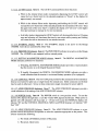
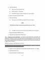
Steps a through e describe the Blood Pressure Reading Cycle used by Oscillometric Monitors to
perform detection and measurement of the oscillations induced in the cuff by the movement of the
arterial wall:
PRESSURE
mm/hg
110
100
CLIFF
PRESSURE
CUFF PRESSURE
200
160
90
80
70
60
50
40
120
S
M
D
I
80
40
30
20
10
0
o
DSCILLATIONS IN CUFF PRESSURE
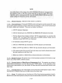
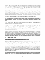
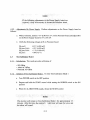
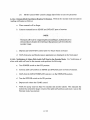
Figure 2-1: Oscillometric Measurement Technique
2-1
DEF.Nnl()l'i:ThemOllitQidefillessy~6Hc>~iess~r~~lliePtessure in the cuff when the
·>:Wagnit~d~oft4e oscilla#()Dsjrid\l<?e~ Wtcrthe.~u.ffcAangefromasteady state to a
cOhstantIY-intteasingrnagnitude:.>
. ...
.... .
.
a. As the cuff is inflated to a suprasystolic pressure (using the same technique as a manual
sphygmomanometer) the artery is occluded so that no blood passes through. At this point, even
though no blood flows under the cuff, there are small pulsations induced into the cuff pressure
by the partially-occluded proximal portion of the artery lying under the cuff (see Figure 2-1).
b. As cuff pressure is reduced, less counter-pressure is applied to the underlying artery, and the
length of the occluded segment of the artery is decreased. At this point, the oscillations in cuff
pressure begin to increase slightly.
c. As cuff pressure continues to be reduced to just below the systolic pressure, the force of the
systolic pressure wave forces the occluded portion of the artery open, blood spurts through the
artery, and the amplitudes of the oscillations increase sharply.
d. With further reduction in cuff pressure: the artery opens for a longer time during each cardiac
cycle, the arterial wall oscillates with a larger amplitude, and cuff oscillations increase markedly
in amplitude until they reach a maximum point. This point of maximum oscillations has been
well-demonstrated to be Mean Arterial Pressure (MAP).
iliepo~tofmaxi~~o~dillatf()nSareeql1artilltiltherati()
MAP and
of air volum e in ...
. ihequff toilie{,61J:,r,~ ofthe arleryltnder toinpress{ofJ exceeds! 0101. Therefore, cuff •.
~.rV'()llim~ shou.ld. i)¢.k¢¢p to a~llimuml>Y usi~~e smalle~tctif(sizepossil>le for
.eachatient
.......
p ...... .
e. With continued cuff-pressure reduction, the underlying artery is open throughout the cardiac
-cycle; the arterial-wall movement is less, and the amplitude of the cuff-pressure oscillations
decrease and then become uniform in amplitude. The point at which the oscillations become
uniform is diastolic pressure.
The OMEGA 1400 also determines the pulse rate by measuring the time between peaks of the cuff-pressure
oscillations and then extrapolating the average number of beats per minute. This average is taken over the
entire Blood Pressure Reading Cycle.
2.1.3 The Importance of Correct Cuff Size. The size of the bladder contained in the blood pressure cuff
is important to prevent erroneous readings. The recommendations of the American Heart Association,
which are contained in their publication Recommendations/or Human Blood Pressure Determination by
Sphygmomanometers, and other references in the Suggested Reading List at the end of this Section, should
be adhered to.
2-2
The American Heart Association makes the following recommendations:
a. "The bladder must be the correct width for the diameter of the patient's arm, for if it is too
narrow, the blood pressure reading will be erroneously high; if it is to wide, the reading
may be erroneously low. The width of the inflatable bladder should be 40% of the
circumference of the mid point of the limb (or 20% wider than the diameter) on which it
is to be used .... "
b. "The length of the inflatable bladder also influences the accuracy of the measurement.
The length of the bladder should be twice the recommended width (bladder length equal
to 80% of arm circumference) .... "
A variety of cuff sizes (both reusable and disposable) for the Omega 1400 are available from Invivo
Research.
2.2
Logical Sequence Theory
2.2.1 Introduction. The following is an overview of the logical sequence the OMEGA 1400
microprocessor follows during normal operation. It serves as a written flowchart of the monitor's
software.
2.2.2 Initial Power-Up. The following is a brief description of the Initial Power-Up sequence:
.
"
'
,
,
. ::.'
: . . . .:,:-,'.'.
If anY9fthe following checks perceive a failure/the monitor
will hang up.
..
a. Performs set up and clears the memory of any previous data in preparation for collection
and storage of oscillatory data.
b. Perfotms short RAM check.
c. Reads user commands from front-panel switches.
(1) Checks Alarms and HilLo Set.
(2) Checks Start.
(3) Checks Hold.
d. Transducer check and EPROM check.
(1 ) Opens transducer to air.
(2) Checks that transducer can be auto-zeroed, and that data is within safety range.
(3) Checks ROM data checksum.
2-3
e. Begins initial reading within 10 seconds if all checks pass.
2.2.3.. Reading Cycle. The following is a brief description of the reading cycle.
.
:
... .
. .. .
.
.
the.fOl1(j~ng
...
.. ... .cheEks,
....... . ·.tbe· monitor will·· ...
Iffailuresareperceived. during·
h~gtip.····
....
.
a. Re-zeros the transducer and checks EPROM data.
b. Closes the valves and begins inflation of cuff.
c. Inflates cuff pressure to the calculated level.
Initial default ==
170 mmHg for Adult Mode
110 mmHg for Neonate Mode
d. Inspects cuff pressure for the presence of oscillations.
e. Steps the cuff pressure downward.
f. Continues searching for and storage of oscillation data.
g. Begins to count number of artifact events. The step sizes range from 14 to 3 torr (mmHg),
. depending on internal software calculations.
h. Stops the oscillation search.
1.
Vents the pressure five oscillation-amplitude steps after the maximum.
J.
The microprocessor searches through the oscillatory data in the memory buffer (RAM)
for the point of maximum oscillations. Tangent lines are constructed from the point of
maximum oscillations to the minimums on either side of this point. The cuff pressure at
the point of maximum oscillations is the value for mean arterial pressure. If the data are
"clean" (i.e., artifact count is low, and/or signal amplitude is large), the value for MAP
is displayed on the front panel.
2-4
es . . . . .
.Th.e . . systolicanddiastolicpressur
.......points . at. which the
ab()ve-mentiolledtangent lin~sjntersectthepr~~sureaxis·.Thesepoints
.are~djusted.asmaybeappropriate,ciue toarti.fact count and/or signal·
q~ality. The systolic and diastolic values are then displayed on th e front
. paneL
k. The microprocessor finds the heart rate by calculating the average time between all
detected-and-stored oscillations. It checks for high time variability and displays the heart
rate.
If the monitor was unable to obtain systolic pressure, but a non-alarm MAP was obtained, there is
a 20-second delay and another reading cycle is initiated. This is not repeated ifno systolic pressure
is obtained after the second attempt.
The followirtgdescribes manual operation of the Interval Del ayModes.
In normaloperation.,the.Intervalsarecpntrp~led by the Omni ';Trak. If··
operator takesmanualccmttol1hetntervm liwilitsbetween the Omni-Trak
. and the Dlonitorwill
nof.tJethesam.e..
' "
- ' "
-
2.2.4 Interval Delay Modes. The following is a brief description of the two interval delay modes:
a. AUTOMATIC INTERVAL: The Automatic Interval mode is entered upon successful
completion of a reading cycle (i.e., no alarm condition or manual intervention).
(1) The Interval delay setting is read, and the time is counted in minutes plus one.
(2) The time since the previous reading cycle has ended is alternately displayed in the
Pulse display.
(3) User commands from front-panel controls are checked (e.g., Alarms-settings
changes, manual Start, Hold, Digital Manometer).
(4) A reading cycle is initiated when the set time has expired.
(5) The Automatic Interval mode is again entered upon successful completion of the
reading cycle.
2-5
b. HOlD MODE: The Hold mode is entered by pressing the HOLD control; the monitor
will signal with one tone and illuminate the Hold indicator.
(1) The time since Hold was initiated is alternately displayed in the DIASTOLIC
display.
(2) User commands from front-panel controls are checked, as in the Automatic Interval
mode.
2.2.5 Digital Manometer Mode. The following is a brief description of the digital manometer
mode:
The Digital Manometer mode is implemented by pressing and holding the HOLD control on the
front panel unti1 two touch tones sound.
a. The cuff pressure is vented (by opening the dump valve) and allowed to stabilize within
the safety range.
h. The transducer is auto-zeroed.
c. The dump valve is closed and the "ALT = D. MANOM." indicator blinks.
d. The cuff pressure is measured by the transducer and displayed in the MEAN display.
2.3
e.
After 60 seconds have elapsed, the monitor automatically exits this mode and opens the
dump valve. It then enters the Hold mode, signals the transition with one tone,
illuminates the Hold indicator, and begins displaying time in Hold alternately in the
DIASTOLIC display.
f.
The last automatically-determined MAP is returned to the MEAN display.
Functional Description
2.3.1 System Overview. The Omega 1400 is a microprocessor-based system. Overall operation
(except for overpressure and failsafe timer) is controlled by the microprocessor (a Z-80) and its
software.
System Timing:
System timing is coordinated by the system clock (crystal controlled at 4 MHz)
which supplies the timing for the microprocessor (2 MHz), interrupt generator
(l MHz), and analog to digital converter (1 MHz).
System Reset:
The system reset is an active reset circuit which holds the system reset during
power-up, and also activates on power-down or power interruptions.
2-6
Memory Select:
Memory select logic, along with microprocessor *RD and *WR lines, select
EPROM memory for software instructions and RAM memory for collected-data
storage or recal1. Along with this select logic the address bus calls for a unique
location to respond. Then, the data bus provides an 8-bit-wide channel to these
responses.
Input Buffer:
The input buffer presents data from the real-time clock to the data bus at the
appropriate time specified by the select logic for interpretation by the
microprocessor front-panel switches.
Output Latches:
Data for output latches is strobed into the output latch buffer by the
microprocessor *WR line; then the appropriate output latch is selected to latch
the buffered data.
2.3.2 Normal Operation. During normal operation, the pump, valve and alarm logic is under
microprocessor contro1. Should the microprocessor malfunction and fail to send a reset to the
failsafe timer logic within three minutes, the failsafe timer will activate, generate an alarm and
disable the pump and valve.
2.3.3 Information Display. To display information, the microprocessor first selects the display to
be updated by using three display latch output decode lines, resets the display, and then sends a
stream of display clock pulses equal to the number to be displayed.
2.3.4 Analog to Digital Converter. The analog to digital converter (ADC) is a single CMOS
integrated circuit. The ADC receives a channel-select command via the microprocessor data bus
and I/O select line to the ADC's address latch enable (ALE). This command sets the ADC's
eight-channel analog multiplexer to one of six active input channels:
a.
b.
c.
d.
e.
2.4
AC line-voltage monitor
+5 V supply-voltage monitor
Adult AC offset
DC offset
Neonatal AC offset
AB08A Processor Boanl
2.4.1 System Clock. The overall system timing (excluding failsafe) is controlled by a basic 4 MHz
clock, consisting of Xl and two gates ofU5. This clock signal is divided into 2 MHz and I MHz
by U4. The 2 MHz output (U4, pin 8) is shaped by active pullup Ql for the microprocessor. The
I MHz output (U4, pin 5) drives the interrupt timer (UI2) and the AID converter (U25).
2.4.2 System Reset. An active reset, made up ofQ9, QIO, QIl, and two gates ofU5, holds system
reset during power-up (approximately 350 msec) until the system clock and supply voltages
stabilize. This reset also activates on power- down or power interruptions, when the +5 V supply
drops below 4.2 V.
2-7
2.4.3 System Interrupt. The interrupt pulse is derived from the 4 MHz system clock, and is utilized
by the microprocessor for all time-keeping functions. The I MHz output ofV4 is fed through ripple
counter V12 and its associated 4 diodes, generating a 200 usec interrupt pulse every 8.4 msec.
2.4.4 Microprocessor and Memory. The microprocessor, a Z-80 type in location VII, utilizes its
control functions (*RD, *WT, *IORQ, and *MEMR) in conjunction with its address lines to access
the program stored in VIS (2764 EPROM). From this stored program, it performs the software
routines for reading the front-panel control switches, input from the AID converter, control for the
pneumatics, displaying information, self-checking the RAM and EPROM memories, and all other
processing functions.
2.4.5 RAM Memory. Two 2114s (V21 and V26) combined, form 1 KByte of RAM memory on
A .. ')8A boards revision S and below or one 6116 2 KByte SRAM on AB08A boards revision T and
ar ~,are used as scratchpad memory for the microprocessor. Software controlled timers (via
in . ..;nupt), pressure and oscillation data, alarm limits, and various other variables collected and
modified by the microprocessor, are stored in RAM.
2.4.6 Memory Select. Memory select is accomplished using upper address lines (A 13, A14, and
A15) and memory request line (*MEMR) to drive the memory select device V6 (a 74HC138). The
memory select logic enables the proper memory device (RAM or EPROM) to be read. The
processor write line (*WR), in addition to this memory select logic, is used to write to RAM.
2.4.7 Failsafe Timer. In case of microprocessor malfunction: a special backup safety timer circuit
is designed to sound the alarm, disable the pump and open the valve to depressurize the cuff.
2.4.7.1 Normal Operation. During normal operation, the microprocessor resets this timer circuit.
Timer V17 oscillates at approximately 45 Hz to provide a time base to counter V16. Counter V 16
divides the pulse rate from timer VI7 by 8192 to cause output-pin 3 to toggle every three minutes,
±30 seconds. During normal operation the counter is kept reset via VB (pin 8).
Counter output U16 (pin 3) is inverted by a gate of U14. This inverted output (active low) is
connected to NAND gate U13, where it enables alarm output The alarm output signal for Q2
disables the valve, and via CR5, disables the pump.
A higher-frequency signal at pin 7 of U16 provides the alarm blink signal, which causes the
alternating tone (if activated on the rear panel board) and the alarm bar indicator to blink on the
display board.
2.4.8 Real-Time Clock. The real-time clock, U27 (a 3835 with software revision OM4D and
below or a DS1202 with software revision OM4E and above), provides seconds, minutes, hours,
date, month, and year data to the microprocessor upon request via I/O line pin 6. Its clock input, pin
2 (32.7 kHz), is provided by inverter U29 and crystal X2. Power for this circuit is supplied via
CR18 (unit power, when on), orCR21 (battery, when unit power is off). R96 is an 82K resistor when
U27 is a 3835 or a 33K when U27 is a DS1202.
2.4.9 Analog to Digital (AID) Converter. This function is performed by a single CMOS IC, U25.
The AID receives a channel-select command via the microprocessor data bus and the address enable
2-8
(AE) line. This command sets the AID's eight-channel analog multiplexer to one ofthe six analog
inputs. A start of convert (ST) signal will cause the AID to convert the analog voltage present on the
selected channel into eight bits of digital resolution. The AID will then place the 8-bit value on the
microprocessor data bus when output enable (OE) is received.
V25, pin I (13), monitors the line signal to determine if the unit is operating from internal battery
or AC line power. V25, pin 2 (14), monitors the unit's +5 V supply voltage. V25, pin 3 (IS),
monitors the unit's internal battery for low battery warning. V25, pin 26, monitors Adult AC
(blood-pressure oscillation) for the Adult mode. V25, pin 27, monitors DC offset (cuffpressure).
V25, pin 28, monitors Neonate AC (cuff-pressure oscillation) for the Neonate mode.
The AID analog inputs are connected through resistor divider networks to reduce input signals to
readable AID levels. Also, for AID protection, diode clamping networks are connected to each
input.
2.4.10 Analog Section. The analog circuits consist of a voltage reference, AC and DC pressure
amplifiers, and their associated filters and AGe.
A + I 0 V reference is supplied by a 723 regulator, VI8, operating from the unit's + 12 V supply. This
+ 10 V reference is coupled through one half of V20 for use by the AID diode clamp network. It is
also divided by R27 and R28, then coupled through the other half ofV20 to supply +5 V reference
for transducer excitation and AID.
OutputofV23, pin I, provides the DC gain signal for the AID, with offset adjusted by R34 and gain
adjusted by R33. The AC component of this signal is fed to V23, pin 5. This half of V23, and the
first half ofVI9, form a 2.5 Hz band-pass filter for blood-pressure oscillations. The output ofV19,
pin 1, is fed to both the adult and neonate AC amplifiers. The adult amplifier has a gain of 2, and
the neonatal amplifier has a gain of 8. See the Calibration section of this manual for adjustment.
2.5
ABOSe Display Board
The Omega 1400 presents information on four three-digit displays, and one two-digit display. This
*information is transmitted from the Processor board to the Display board viaPl, using three decode
lines (AO, Al and A2), a reset line and a clock line.
Information is transmitted to any display through demultiplexers VIO and Vll, selected by the
decoder lines. The display is first reset by a signal gated through VIO to the three-digit BCD
counterllatch, (V2, V4, V6, V8 or V14, depending on which display is selected). Then, clock pulses,
equaling the number to be displayed, are gated through VII to the selected three-digit counter and
latched in through BCD latches.
The counter then sequentially outputs each digit (units, tens, hundreds) to the BCD to seven-segment
drives (VI, V3, V5, V7, or VI4) along with corresponding transistor-driver enabling lines (DSI,
2-9
DS2, or DS3), turning on one digit at a time. Leading-zero blanking is accomplished by using the
"Ft! segment to disable the driver transistor for the hundreds digit.
Outputs from UIO and UII are also used to set/reset flip-flops UI2, driving the indicators for
ADULT or NEONATE. All other indicators are driven directly from the Processor board.
The Display board also interconnects the front-panel switches to the Processor board, signal "tone"
from the Processor board to the Rear Panel Control board, and signal "alarm blink" from the Rear
Panel Control board to the Alarm bar indicator.
2.6
ABOSD Rear Panel Control Boanl
The Rear Panel Control board provides control for and generation of alarm tone, as well as
interconnect to the Display board, valve and pump drive circuit.
UI is designed as a free-running oscillator, with its frequency altered from High, Low, or
Alternating tones, by Q6 and S2. UI's output is connected to volume control R25, and is turned on
and off by Q2, which is driven by the processor alarm signal.
The speaker amplifier (UI, Q3, Q4, and Q5) is driven by the touch-tone generated by the Processor
board through touch-tone volume control RI8, or alarm oscillator UI through alarm volume control
R25.
Signal alarm blink (11, pin 2) is connected to Switch 2 for alternating alarm tone, and through CRI
to the Display board for Alarm bar indicator blinking.
2.7
AP21 Pump-Drive Assembly
The pump-drive assembly (mounted directly on the pump) provides control of the pneumatic system
pressurization when commanded by the pump signal from the Rear Panel Control board. J2 receives
regulated + 12 VDC, and the pump-control signal from the Rear Panel Control board.
Unregulated DC from the Power Supply board is received at 11 to power the pump.
When a pump-signal command is received, the pump signal input goes high (12 VDC), turning on
FET QI, and switching the regulated + 12 VDC through a voltage divider, consisting ofRl and R2
(voltage drop across the FET is negligible). This applies a signal of approximately +9 VDC to the
base of Darlington switch Q2, and results in the application of a controlled voltage of +8.5 to 9.0
VDC to the pump motor. Pump "soft start" is provided by Q3 and R3 by current limiting the pump
to approximately 1 amp.
2-10
The pump pressurizes the pneumatic system until commanded by the system to stop. When the
pump signal is low (0 VDC), FET Q1 is turned off, voltage at the base of Q2 is zero (Q2 is turned
off), and no voltage is applied to the pump motor.
.
.
NOTE
#mp-iIri\i~:isigxtidycif~e~.t~i>on,ctilic4;I~dlll"t.
,~ai.vas
nili2k;as
20., "orcont
.
...
.
.
without affecting theoperatiollof the system..
2.S
Power Grtuitry
The Omega 1400MRI receives power from the Omni-Trak unit through the serial port on the rear
panel.
2.9
ABOSF2 Power Supply Boam
The Power Supply is a dedicated, switching, three-voltage output supply, designed to make
high-efficiency use of the power provided by the Omni-Trak. This is accomplished by a
single-ferrite transformer which provides the three DC voltages (+5, +12, and -8) required by the
system.
The +5 volt supply is regulated by the switcher duty cycle, and the +12 volt and -8 volt supplies are
regulated by conventional linear means.
2.10
AB20A Protocol Converter Boam
The Protocol Converter Board provides control communications to the Omega 1400 NIBP for the
Ornni-Trak 3100 MRI. When communication is active between this board and the Omni-Trak, the
Omni-Trak takes control of the Omega 1400. Under this control, the Omega 1400 alarms and
interval controls are disabled and controlled through Omni-Buss communications. If there is no
communication between the Omni-Trak and the Protocol converter, the Omega 1400 will operate
under it's own Alarm and Interval controls.
2.10.1 Connection. The Protocol Converter board connects to the Omega 1400's AB08A
Processor board via it's dual 26 pin connector J2. This connection provides power and
communication between the monitor and the Omni-Trak.
2-11
2.10.2 Reset. An active reset, made up of Q 1, Q2, and Q3, holds system reset during power-up
(approx. 350 ms) until the system clock and supply voltages stabilize. This reset also activates on
power down or power interruptions, when the +5 V supply drops below 4.2 V.
2.103 Microprocessor and Memory. The microprocessor, a Z-80 type in location UI, utilizes its
control functions (*RD, *WT, *10E and *ME) in conjunction with its address lines to access the
program stored in U2 (27256 EPROM). From this stored program, it performs the software routines
for communication via it's two TX and RX channels self checking the RAM and EPROM memories,
and all other processing functions.
2.10.4 Memory Select. Memory selectis accomplished using upper address lines (A 13, A14, and
A 15) and memory request line (*ME) to drive the memory select device U5 (a 74HCOO). The
memory select logic enables the proper memory device (RAM or EPROM) to be read. The
processor write line (*WR), in addition to this memory select logic, is used to write to RAM.
2.10.5 Omega 1400 COMM. The processor's RXA1line (pin 49) receives information from the
Omega 1400 via it's PR SERIAL and HOLD LED lines through gate U6, and the processors TXA 1
line (pin 48) transmits information to the Omega 1400 through a gate and latch network made up
ofU4 and U6.
2.10.6 MRI Omni-Trak 3100 COMM. The processor's RXAO (pin 46), TXAO (pin 45), *CTSO
(pin 43), and *RTSO (pin 42) provides communication to Omni-Trak 3100 through RS232
DriverlReceiver U7.
2-12
SUGGESTED READING LIST
American Heart Association, Recommendations for Human Blood Pressure Detennination by
Sphygmomanometers, (1980).
Geddes, L.A, Cardiovascular Devices and Their Applications, John Wiley & Sons, Inc. (New York,
1984).
Geddes, and Tivey, R. "The Importance of Cuff Width in Measurement of Blood Pressure
Indirectly," Cardiovascular Research Center Bulletin (Jan.-March, 1976).
Geddes, and Newberg, D.C. "Cuff Pressure Oscillations in the Measurement of Relative Blood
Pressure," Psychophysiology (Vol. 14, No.2).
Geddes, Voelz, Combs, Reiner, and Babbs, "Characterization of the Oscillometric Method for
Measuring Indirect Blood Pressure," Biomedical Engineering Center, Purdue University.
Mauck, Smith, Geddes, and Bourland, "The Meaning of the Point ofMaxim um Oscillations in Cuff
Pressure in the Indirect M easurem ent ofBlood Pressure--Part II," Transactions of the ASME, (VoL
102, February 1980).
Morgan, Mark, "A n Introduction to Blood Pressure Measurement and the Om ega Series Monitors,"
Invivo Research Laboratories, Inc. (1984).
Posey, Geddes, Williams, and Moore, "The Meaning of the Point ofMaxim um Oscillations in Cuff
Pressure in the Indirect Measurement of Blood Pressure. Pan I," Cardiovascular Research Center
Bulletin (July-September 1969).
Ramsey, M. "Noninvasive Automatic Detennination of Mean A rterial Pressure," Med. BioI. Eng.
Comput., (17, II-I8, 1979).
2-13
SECTIONll
CALmRATION MODES
This section describes the three calibration modes which provide for a "cover-on"
calibration check of the OMEGA 1400 Series Monitors .
.
','
'.-
.
.
,.
····Forfurtherinformation~mt6eC~ibratioh modes, refer to
SectionIV;Calibratioriand VeHfication.
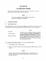
3.
CALIBRATION MODES
3.1
Test-CaJibration Mode 1
Test-Calibration Mode I does not require that the OMEGA 1400 Monitor's cover be removed, and
does not require any external test equipment. Test-Calibration Mode 1 checks the following:
NOTE
• DC Offset
• Adult AC Offset
• Neonatal AC Offset
DC Offset, Adl.llt AC Offset and Neonatal AC Offset
are.key.yoltag~sand >MUST .BECHECKED. A
MINIMlJMOFEVERY Srx.MONTIIS;Exceptwhere
noted,thehoses>shouldootbecorinected to either .the
SeI1seorInfiat~ portsonthefrolltofthemonitor, or
the>MarI0 eter<porloritherear<ofthe.monitor during
these callbrationprocedures.
.
l1
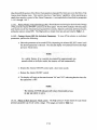
3.1.1 Initiation of Test-Calibration Mode 1. To enter Test-Calibration Mode 1:
a. Tum POWER switch to the OFF position.
b. Depress and hold the START control while turning the POWER switch to the ON
position.
The monitor will remain in Test:-Calibration Model for approximately 3:5
will open the. valve, and
the 3.larrnwiU s o u o d . ·
..
rriinutes;Afterthistime~themonitor'sfailsaf'etimer
3-1
c. When the ALARM TONE sounds, release the START control.
d. Observe the following indications:
(1) ALARM indicator is flashing.
(2) MAIN display indicates" 188" then "288."
(3) INTERVAL display indicates "88."
(4) All INDICATORS (except NEONATE) are on.
(5) SYSTOLIC display indicates the DC Offset of the internal pressure transducer. This
must read between 3 and 9 torr.
(6) DIASTOLIC display indicates the Adult AC Offset of the pressure transducer. This
must read 80 ±5.
(7) PULSE display indicates the Neonatal AC Offset. This must read 80 ±5.
The AC Offsets may also be used to detect excessively-noisy pressure transducers. This is done by
checking the AC Offsets for fluctuations from their normal values of 80 ±S. If the readings rapidly
fluctuate by more than two units on the Adult AC Offset (in the Diastolic display), or by more than
four units on the Neonatal AC Offset (in the Pulse display), it is advisable to confirm the status of
the transducer by means of an oscilloscope (see Section IV).
3.1.2 Manual Leak Test. An automatic leak test is performed in Test-Calibration Mode 3 (See
Paragraph 3.3). If desired a manual leak test may be performed as follows:
a. While in Test-Calibration Mode 1, connect a standard mercury manometer and handbulb
with a "T" fitting to the Sense Port on the monitor. The pressure will be shown in the
MEAN display.
b. Apply 200 torr with the handbulb. The pressure shown in the MEAN display should read
±3 torr of the manometer's reading. If not, see Section IV, for adjustment procedure.
c. Observe the pressure reading for one minute. If the pressure drops 20 torr per minute or
more, the pneumatic system is faulty.
3.1.3 Test-Calibration Mode 1 Exit. To exit Test-Calibration Mode 1, tum the POWER switch to
the OFF position.
3.2
Test-Calibration Mode 2
Test-Calibration Mode 2 performs an automatic RAM check.
3-2
3.2.1 Initiation of Test-Calibration Mode 2. Test-Calibration Mode 2 may be entered by two
methods:
a. From Test-Calibration Mode 1:
(1) Depress and hold the START control.
(2) When ALARM TONE sounds five times, release the START control.
(3) The monitor will enter Test-Calibration Mode 2.
b. From Power Off:
(1) Depress and hold the START control, and tum POWER switch to the ON position.
(2) When ALARM TONE sounds five times, release the START control.
(3) The monitor will enter Test-Calibration Mode 2.
3.2.2 RAM Test. The RAM test automatically begins with "00" in both the SYSTOLIC and
DIASTOLIC displays. The SYSTOLIC display is now a "pass" counter for the RAM test, and will
increment by one for each error-free pass. If a RAM test failure occurs, the unit will alarm, and the
pass counter will stop. After 3 112 minutes in this mode, the unit will automatically alarm (failsafe),
but the pass counter will continue.
3.2.3 Test-Calibration Mode 2 Exit. To exit Test-Calibration Mode 2, tum the POWER switch to
the OFF position.
3.3
Test-Calibration Mode 3
Test-Calibration Mode 3 performs an automatic leak test on the pneumatics system of the monitor.
3.3.1 Initiation of Test-Calibration Mode 3. To enter Test-Calibration Mode 3:
a. . Close- the pneumatic circuit by connecting the patient hose and cuff to the SE
INFLATE ports, and wrapping the cuff tightly around a 3" tube or other suitable hard
surface.
b. Tum the POWER switch to the OFF position.
c. Depress and hold the HOLD control while turning the POWER switch to the ON position.
d. The monitor will begin the automatic leak test. The test will repeat until interrupted.
3-3
3.3.2 Automatic Leak Test. The monitor will inflate approximately 200 torr and begin a
30-second leak test. If the beginning and ending pressures differ by 10 torr or more, this test will
be counted as a failure. The SYSTOLIC display will show the number ofleak tests completed and
the DIASTOLIC display will show the number of leak failures. The Mean display will show the
beginning pressure and the PULSE display will show the current pressure during the leak test.
3.3.2.1 Valve and Pump Test. During the Automatic Leak Test, the valve and pump are checked
for the following:
a. Strength of Pump (ability to start against pressure).
b. Opening and closing of valve (ability to open against High pressure and ability to fully
close with Low pressure.
3.3.3
Omega 1400s With Rev 47 or Greater. In Omega 1400s with Rev. 47 or greater software,
a brief test of valve speed is conducted immediately after the conclusion of a successful leak test.
This test's "fail" count is shown on the INTERVAL display.
'NQTE
The valv~spt:;edtest can orilybeconductedwithlhecorrect leak
teSt load (vglurne) connected; Any other volurqem~y give false
valve pas~ifailiridications.A10"ft.I¢ngtliofV8"i.v,tubing
·win·providethecorrectyolumetort1ii~t~st.
3.3.4 Omega 1400s With Rev 48 or Greater. In Omega 1400s with Rev. 48 and greater software,
every second test will be a low pressure leak test After performing the high pressure leak test and
valve speed test, the monitor will inflate approximately 30 torr and begin the 30-second low
pressure leak test. If the beginning and ending pressures differ by 10 torr or more, this test will be
counted as a failure. The SYSTOLIC display will show the number of leak tests completed and the
DIASTOLIC display will show the number of leak failures. The MEAN display will show the
beginning pressure and the Pulse display will show the current pressure during the leak test.
The monitor will not perform a valve-speed test after the low pressure leak test.
3.3.5 Test-Calibration Mode 3 Exit To exit Test-Calibration Mode 3, tum the POWER switch
to the OFF position.
3-4
SECTION IV
CALffiRATION AND VERlFICATION PROCEDURES
This section describes the calibration and verification procedures which are used to maintain the
Omega 1400 series of Oscillometric Monitors.
4.
CALmRATION AND VERIFICATION PROCEDURES
4.1
Calibration Checkout
4.1.1
Introduction. Refer to Section III: CALIBRATION MODES, for "cover on" checkout of
the following:
•
•
•
•
•
DC Offset
Adult and Neonatal AC Offset
Transducer Calibration
Leak Test
RAM Check
Should any of these calibration requirements arise from running any of the three Test-Calibration
Modes, refer to the paragraph which outlines the calibration procedures for correction of the failure.
4.2
Power Supply Calibration
Use ground reference at"TP Ground"
on.Processor board.
..
4.2.1
Calibration Setup. Perform the following procedure to ready the Omega 1400 monitor for
calibration:
a. Connect monitor's serial port to MRI Omni-Trak, or to a 24 VDC Power Supply (
negative to 1/0 Port Pins 14, 15 and 16; positive to 1/0 Port Pins 11, 12 and 13).
b. Tum Front-Panel POWER switch to the ON position.
c. Depress and release HOLD control to place monitor in the Hold mode.
4-1
NOTE····
lfthefolloWihg acljustmentstOthePo~erSupplyboird.are
·r~qllited>.jtt1laybeIlecessalyt§¢leva.tet~eProq~~sorboard,
4.2.2 Adjustments On Power Supply. Perform adjustments on the Power Supply board as
follows:
a. With a voltmeter, monitor +5 V at 18 Pin 3 or 4, on the Processor board, and adjust R31
on the Power Supply board for 5 V, ±50 mY.
b. Verify the following voltages at 18 on Processor board:
18, pin 8:
18, pins 5 & 6:
18, pins 3 & 4:
19, pin 3:
-8.3 V (±300 mY)
+12 V (±500 mY)
+ 5 V (±100 mY)
+18V (±2 V)
4.3
Test-Calibration Mode 1
4.3.1
Introduction. This mode provides calibration of:
• DC Offset
• Adult AC Offset
• Neonatal A C Offset
4.3.2
Initiation of Test-Calibration Mode 1. To enter Test-Calibration Mode 1:
a. Tum POWER switch to the OFF position.
b..
De~ress
and hold the START control while tuming the POWER switch to the ON
position.
c. When the ALARM TONE sounds, release the START control.
The.· monitbrwiUremain in Test~Cali'brationMo<lel.f()r. apprQx~mattHy. 35
minutes. Aftertbisfime;the mqnito['s j ·lsafetirner willoperi the valve, and
theaihlmwiI1s6und..·
.
..
4-2
..
.
d. Observe the following indications:
(1)
ALARM indicator flashes with each alarm tone.
(2)
MAIN display indicates "188" then "288."
(3)
INTERVAL display indicates "88."
(4)
All
(5)
SYSTOLIC display indicates the DC Offset of the internal pressure transducer.
This must read between 3 and 9 torr.
(6)
DIASTOLIC display indicates the Adult AC Offset of the pressure transducer.
This must read 80 ±5.
(7)
PULSE display indicates the Neonatal AC Offset This must read 80 ±5.
(8)
The Rear-Panel VOLUME control is functional, and the Rear-Panel ALARM
TONE control functions as follows:
I~'DICATORS
(except NEONATE) are on.
UP POSITION:
CENTER POSITION:
DOWN POSITION:
e.
LOW CONSTANT TONE
NORMAL CONSTANT TONE
ALTERNATING TONES
Within 11.5 seconds from POWER ON, the valves should close, and displays are in
Calibration mode.
4.3.3
Analog Adjustments On Processor Board. Perform analog adjustments on the Processor
board as follows:
REFERENCE:
With a volt meter, monitor the +5 V reference voltage at "TP +5 V REF", and
adjust R31 for 4.995 VDC. (±0.005 VDC).
DC OFFSET:
With SENSE INPUT port open, adjust R34 for "06" in the SYSTOLIC display.
ADULTAC
OFFSET:
Adjust R90 for "80" in the DIASTOLIC display.
NEONATAL
AC OFFSET:
Adjust R32 for "80" in the PULSE display.
4-3
SENSE PORT:
Using a standard mercury manometer and handbulb connected to Sense port with
a "T" fitting (see Figure 3), apply 200 mmHg pressure with the handbulb. Adjust
R33 for "206" in the SYSTOLIC display. Remove pressure from SENSE port.
If necessary, adjust DC offset, as described above. Then reapply pressure source, and apply the
pressures listed in Table 4-1, noting values in the SYSTOLIC display:
Table 4-1: Systolic Pressures and Tolenmces
·········INPlJT.PRESSURE .
SYstOLIC. DISPLAY .•
.•.. . TOLERANCE . . .•.
00
06
±1
50
56
±1
100
106
±1
150
156
±1
200
206
±1
4.3.4
Failsafe Alarm Test. Perform the following procedure to that the Failsafe Alarm functions
properly:
a.
Tum the POWER switch to the OFF position.
b. Reenter Test-Calibration Mode 1 by depressing and holding the START switch while
turning the POWER switch to the ON position.
c. Begin timing the failsafe timeout. The monitor should alarm in 3 minutes (+25/-30
seconds) from the start of elapsed time at POWER ON.
4.4
Test-Calibration Mode 2
4.4.1
Initiation of Test-Calibration Mode 2. Test-Calibration Mode 2 may be entered by two
methods:
a. From Test-Calibration Mode 1:
(1)
Depress and hold the START control.
(2)
When ALARM TONE sounds five times, release the START control.
(3)
The monitor will enter Test-Calibration Mode 2.
4-4
b. From Power Off:
4.4.2
(1)
Depress and hold the START control, and tum the POWER switch to the ON
position.
(2)
When ALARM TONE sounds five times, release the START control.
(3)
The monitor will enter Test-Calibration Mode 2.
Analog Verification. Perform analog verification as follows:
a. Ensure ADULT /NEONATAL selector is in the ADULT position.
b. Tum Front-Panel POWER switch to the ON position.
c. Place unit in Hold mode.
d. Connect a function generator as follows:
(I)
Disconnect the transducer from 13 on the Analog board.
(2)
Connect a function generator to "SIGNAL" (13, pin 3) and to "GROUND" (Jl,
pin 2).
e. Using oscilloscope, monitor "TP P2" test point, and verify that the following peak
signals occur:
(1)
Set function generator output for 2.5 Hz sinewave at 25 mV peak to peak. On
oscilloscope, verify peak signal occurs at 2.5 Hz (4 V peak to peak, ±0.4 V).
(2)
Adjust function generator to 0.8 Hz. On oscilloscope, verify half-peak signal (2
V peak to peak, ±0.2 V).
(3)
Adjust function generator to 9 Hz. On oscilloscope, verify half-peak signal (2
V peak to peak, ±O.2 V).
(4)
Set function generator output for 9 Hz sinewave at 25 mV peak to peak. On
oscilloscope, verify a gain of four (4) between signal input at 13 Pin 3 and U23
Pin 1 (100 mV peak to peak, ±20 mY).
4-5
4.4.3
(5)
On oscilloscope, verify gain of ten (10) between U23 Pin 1 and U19 Pin 1 (1 V
peak-to-peak, ±200 m V).
(6)
On oscilloscope, verify gain of two (2) between U28 Pin 1 and "TP P2" (2 V
peak to peak, ±400 mV).
(7)
On oscilloscope, verify gain of eight (8) between U19 Pin 1 and "TP AC", (8 V
peak to peak, ±1.6 V).
Transducer Verification. Perform transducer verification as follows:
..
~
.
.
.
.
.
.
NOTE·
... ,
'.
-
,
. , . . ...
..
."
.
~
Ifthe·.transducerisnoisy.tbe.noise~tf~~pear
.•·• • • •
• as •.a JO\\fifrequency
•jUrIlpiIigoff of center (popcom. noise). Tathe(than .ahigh..frequency
····.whitenoise.PopcorDI1oiseill eicess dt200 I1lY· ~ILrequire tltafthe
transallcerberepbicediopfevel1Y·inatctifatereadings:· ..
:. -,':::< ''; ','; . ',.::':.' -, -: -:,:: -::-.
.
, ','
.
: :. ,::
,::,,' .::.::: ~: ',":::. :'::'::/
...
.
-' ',:,-,:,
:, ", ,:': ':,
..
. :~. ,: ,.'>,:
.
,,
.
. • '·P{)pcofu noiselllay only occur every .l?seconds;therefore, monitor
thistesipointat least 15secorids.
't
a. Reconnect the transducer to J3 of the Processor Board.
b. Set Oscilloscope to 50 mV per division and monitor "TP AC" test point.
c. Verify that noise is less than 200 m V peak-to-peak. This test should be conducted with
no pressure in the pneumatic system.
4.4.4
Alarm and Hold-Mode Verifications. Perform Alarm and Hold verification as follows:
a. Open SENSE and INFLATE ports.
h. Depress and release the START control.
c. Monitor will ALARM at the end of the Pump Cycle.
d. Depress and release the HOLD control.
e. Verify that the Alarm Condition is Cancelled.
f.
Depress and release the HOLD controL
4-6
g. Verify the following:
(l)
The monitor enters the Hold mode.
(2)
HOLD indicator is illuminated.
(3)
DIASTOLIC display indicates a blinking "01" (time in Hold).
h. Depress and release the START control.
1.
Verify the following:
(1)
The monitor exits the Hold mode and the Pump Cycle begins.
.
',"-."
,
.
,-,.,-,,-
',,-;"
.--
'.
,
in 8 • ·~I1the Rear Panel"" Control. boardC()ntrolstlibto~chton~. yolume,
(2)
J.
An audible Touch Tone is heard each time the START control is depressed.
Depress and release the HOLD controL
k. Verify that the monitor enters the Hold mode.
4.4.5
Overpressure Switch Adjustment. As a pneumatic system safety feature, the Omega 1400
employs an Overpressure Switch, which senses successive system pressures and turns the monitor
off until the overpressure situation has cleared. This switch has adjustable pressure trip-points, and
may require occasional checks and readjustments, especially when the monitor has been exposed
to high vibration situations.
Perform Overpressure Switch adjustment as follows:
a. Connect a mercury manometer and hand-bulb to the Inflate port with a "T" fitting.
b. Open the hand-bulb valve.
c. Depress and release the START control.
4-7
d. Slowly close the hand-bulb valve while monitoring the pressure on the manometer.
Increasetllepressure at a rate notgreaterthan2mmlIglsec6Iid .
. . . towards the a.6tivatibri (monitor Jlo{y~r~doWri)point. Increasing.·.· .
•\pressur~t92·rapidly~~I>giv~>afa.1s~ • . trpT:pointindicatio~;
e.
4.4.6
Adjust the Overpressure Switch to activate (power-down monitor) at 270 mmHg (±14
mmHg).
Digital Manometer Verification. Perform Digital Manometer Verification as follows:
a. Depress and hold the HOLD controL
b. Verify that upon second audible touch tone, the "ALT = D. MANOMETER" indicator
begins to blink.
c. Start elapsed timing when valve closure is heard.
d. Verify that the monitor automatically exits the Manual Manometer mode with an
audible tone in 60 (±2) seconds from the start of elapsed time.
e. Connect a mercury manometer and handbulb to the Sense port on the front panel of the
monitor.
f.
Re-enter the Manual Manometer mode by depressing and holding the HOLD control.
g. With the hand-bulb, apply 250 mmHg.
h. Verify that the Mean display is showing 249 (±1) torr.
4-8
4.5
Test-Calibration Mode 3
4.5.1
Initiation of Test-Calibration Mode 3. To enter Test-Calibration Mode 3:
a. Close the pneumatic circuit by connecting the patient hose and cuff to the SENSE and
INFLATE ports, and wrapping the cuff tightly around itself.
b. Tum the POWER switch to the OFF position.
c. Depress and hold the HOLD control while turning the POWER switch to the ON
position.
d. The monitor will begin the automatic leak test. The test will repeat until interrupted.
4.5.2
Automatic Leak Test. The monitor will inflate approximately 200 torr and begin a
30-second leak test. If the beginning and ending pressures differ by 10 torr or more, this test will
be counted as a failure. The SYSTOLIC display will show the number of leak tests completed and
the DIASTOLIC display will show the number of leak failures. The l\1EAN display will show the
beginning pressure and the PULSE display will show the current pressure during the leak test.
4.5.3
Alarm Function Test (Adult Mode).
Eoi>gel1efafinformation On the fuilctioning ofthe a1arnisand setting
alarm parameters,see Section I: Operation, ALAR,MSsection.
4.5.3.1 Alarms Parameter Select Verification. Perform Alarms Parameter Select Verification as
follows:
a. Ensure that the monitor is in the Adult mode.
h. Tum the Front-Panel POWER switch to the ON position.
c. Depress and release the HOLD control.
d. Verify ALARM ACTIVE indicator is illuminated.
e. Depress and release the Alarms SELECT control.
4-9
f.
Verify the following:
(1)
Touch Tone "Imnds.
(2)
MEAN display alternates between 135 and 55 (preset limits).
g. Depress and release Alarms SELECT control.
h. Verify the following:
(I)
Touch Tone sounds.
(2)
SYSTOLIC display alternates between 190 and 65 (preset limits).
1.
Depress and release Alarms SELECT control.
J.
Verify the following:
(1)
Touch Tone sounds.
(2)
DIASTOLIC display alternates between 125 and 40 (preset limits).
k. Depress and release Alarms SELECT control.
I.
Verify the following:
(1 )
Touch Tone sounds.
(2)
PULSE display alternates between 160 and 45 (preset limits).
m. Depress and release Alarms SELECT control.
n.
De~ress
and hold Alarms ON/OFF controL
o. Verify the following:
(I)
All alarms are reset to 255/00
(2)
Alarms ACTIVE indicator extinguishes.
p. Release Alarms ON/OFF control.
q. Depress and release Alarms ON/OFF control.
4-10
r.
Verify Alarms ACTIVE indicator illuminates.
s. Verify ill SET and LO SET will change alarm parameters in anyone display.
4.5.3.2 "Dead-Man" Alarm Test. Perform the "Dead-Man" alarm test as follows:
a. Close the pneumatic circuit by connecting the patient hose and cuff to the SENSE and
INFLATE ports, and wrapping the cuff tightly around itself.
b. Depress and release the START control.
c. When the CYCLE Lamp illuminates, start elapsed time.
d. Verify that unit alarms in less than 75 seconds.
4.5.3.3 Pneumatic Impedance Test. Perform the pneumatic impedance test as follows:
a. Close the pneumatic circuit by connecting the patient hose and cuff to the SENSE and
INFLATE ports, and wrapping the cuff tightly around itself.
b. Depress and release the START control.
c. Monitor will inflate cuff.
d. When monitor has stopped pumping, immediately depress and release the HOLD
control.
e.
Verify that the unit enters the HOLD Mode.
f.
When "01" appears in the DIASTOLIC display, depress and release the START control
and start elapsed time.
g. Verify the pump reactivates within 5 seconds.
h. Depress and release the HOLD control.
4.5.3.4 Interval Verification and Test. Perform the interval verification and test as follows:
a. Depress and release the ill SET control.
b. Verify the following:
(1)
Touch Tone sounds.
4-11
(2)
INTERVAL display increments by one.
c. Repeat until "ones" position in INTERVAL display indicates "9".
d. Depress and hold the HI SET control.
e. Verify that the INTERVAL display increments by 10's, up to "99".
f.
Release the HI SET control.
g. Depress and release the LO SET controL
h. Verify the following:
(1)
Touch Tone sounds.
(2)
INTERVAL display decrements by one.
1.
Repeat until "ones" position in INTERVAL display indicates "0",
J.
Depress and hold the LO SET control.
k. Verify that the INTERVAL display decrements by lO's, down to "00",
I.
Release the LO SET controL
m. Depress and hold the LO SET control.
n. Verify a continuous Touch Tone,
o. Release the LO SET control.
4.5.3.5. Verification of Alarm with Neonatal Cuff Used in Adult Mode. Perform verification of
alarm with the neonatal cuff used in adult mode as follows:
a. Connect neonatal cuff and hose to SENSE and INFLATE ports.
b. Ensure the ADULTINEONATE selector is in the ADULT position.
c. Tum the POWER switch to the ON position.
d. Depress and release START control.
4-12
e. Verify that the pump runs for less than 3 seconds, and monitor alarms. This indicates
that the monitor has sensed the small volume of the neonatal hose and cuff, and since
it was in the ADULT mode, has alarmed.
4.5.3.6 AduItlNeonate Selector Lock-Out. Test the adult/neonate selector lock-out as follows:
a. Place the ADULTINEONATE selector in the ADULT position.
b. Tum the POWER switch to the ON position.
c. Switch the ADULTINEONATE selector to the NEONATE position.
'J)EFlNm()N: LOCKUP means total loss ofopenitofeontrol, with Illonitor.remainingi n
cotlstantalarm.
d. Verify the following:
(I)
The monitor alarms.
(2)
All displays show "00".
(3)
Monitor locks up.
e. Tum the POWER switch to the OFF position.
4.5.4
Alarm Function Test (Neonate Mode).
For. generaiinformationon thefuttctionirrgof1he .al anns"see
Section L Operations, Alarms section.
4.5.4.1 Alarm Select Verification. Perform alarm select verification as follows:
a. Tum the POWER switch to the OFF position.
b. Set the ADULTINEONATE selector in the NEONATE position.
c. Tum the POWER switch to the ON position.
4-13
d. Verify that Alarms ACTIVE indicator is illuminated.
e. Depress and release Alarms SELECT control.
f.
Verify the following:
(1)
Touch Tone sounds.
(2)
MEAN display alternates between "100" and "30" (the preset alarm limits).
g. Depress and release Alarms SELECT control.
h. Verify the following:
(1)
Touch Tone sounds.
(2)
SYSTOLIC display alternates between" 130" and "40" (the preset alarm limits).
I.
Depress and release Alarms SELECT control.
J.
Verify the following:
(1)
Touch Tone sounds.
(2)
DIASTOLIC display alternates between "80" and "25" (the preset alarm limits).
k.
Depress and release Alarms SELECT control.
1.
Verify the following:
(1)
Touch Tone sounds.
(2)
PULSE display alternates between "220" and "60" (the preset alarm limits).
m. Depress and release Alarms SELECT control.
n. Depress and hold the Alarms ON/OFF control
o. Verify the following:
(1)
All alarms alternate between "255" and "00" (this indicates that alarms are
inactive).
(2)
Alarms ACTIVE indicator extinguishes.
4-14
(3)
HI SET and LO SET controls change alarm limits on anyone parameter.
4.5.4.2 Neonate Mode Non-Patient Reading Verification. Perform the neonate mode non-patient
reading verification as follows:
a. Place neonatal cuff on finger.
b. Connect neonatal hose to SENSE and INFLATE ports of monitor.
··NOTE
Neonatal·cllffmustbe.\Vfappedtight1yaroundfinger~and handrnustbe
elevated aboveshoulder}evel to Ensure that pressures will be within the
neonatal range.
c. Depress and hold START control until two Touch Tones are heard.
d. Verify that pulse and blood pressure parameters are displayed on the front panel.
4.5.4.3 Verification of Alarm With Adult Cuff Used in the Neonate Mode .. For Verification of
alarm with adult cuff used in the neonate mode perform the following:
a. Tum POWER switch to the OFF position.
b. Connect adult cuff and hose to SENSE and INFLATE ports on front of monitor.
c. Verify that the ADULTINEONATE selector is in the NEONATE position.
d. Tum the POWER switch to the ON position.
e. Depress and release the START control.
f.
Verify the pump runs less than five seconds and monitor alarms. This indicates the
monitor has sensed the larger volume of the adult cuff and hose, and since it was in the
Neonate mode, has alarmed.
4-15
SECTION V
lROlJBLESHOOTING
This section outlines the procedures to follow in the event of an Omega 1400 system
failure.
5.
TROUBLESHOOTING
. CAUTION
,
"".
.
-...
- .
If eorrecfoperationofthe Omega ·1400 isinqiIestion,removeitfmmi:linical sewice
imrriediately; It should theIr be retumedto quaiifiedservice personnel for. repair.
5.1
Initial Inspection
Many of the cases in which an Omega 1400 monitor exhibits erroneous readings (or no readings at
all), are caused by the various forms of artifact. Table 5-1: "Probable Causes of Monitor Being
Unable to Determine Pressures" contains a list of the various artifact - either from the patient,
external from motion or other problems - which could cause the monitor to exhibit failure
indications. Refer to Table 5-1 first, then if unable to determine cause proceed to paragraph 6.2.
5.2
Operation Checkout
5.2.1 Visual Inspection. Perform a visual inspection as follows:
<Vismil Inspection should be· performed in~ntirety. Correctany
discrepancies which are uncovered before moving on to the next
inspection step.
a. Inspect the monitor externally for obvious discrepancies (such as visible damage, cracks
or debris) which could cause failure.
5-1
Table 5-1: Probable Causes of Monitor Being Unable
to Detennine Pressures
r'
.
:.·PROBLEM
.' •. " .. ,>.' ....
.....
'
.> •.....
.
I: ..•..........
..
..
...
..
'. . . ,. • . ..,'. i. ··.·.PROBNBLECAlJSE
.... ·..... . ......
,. ................, ...... , .
. .>
.
.
.. '
. ...
Motion Artifact
l.
2.
3.
Patient movement
Cuff movement
Hose movement
Signal Artifact
l.
2.
3.
4.
Erratic heart rate or pulse
High electrical noise environment
Large room-pressure changes
Highly-variable blood pressure on a beat to beat
basis.
Weak Pulse Amplitude
(Not low blood pressure)
1.
2.
3.
4.
5.
6.
7.
Low cardiac output
High vascular tone
Arteriosclerotic vessels
Patient in shock
Deep anesthesia
Obesity
Weak Pulse
Low Oscillation Amplitude
(to the monitor)
l.
2.
3.
Cuff too loose
Improper cuff placement
Hose not connected properly
Low Inflation Pressure (under
Systolic)
l.
The patient's systolic pressure is higher than the
monitor has inflated the cuff. (This might occur
during intubation, at surgical stimulation, etc.)
High Inflation Pressure
(over Systolic)
l.
The patient's systolic pressure is much lower
than the monitor has inflated the cuff. (This
might occur as patient is being anesthetized, for
example.)
b. Open "the monitor and inspect internally for obvious discrepancies.
c. Inspect fuses and holders for obvious discrepancies (such as discolorization and/or
corrosion).
d. Inspect cable connectors for connection integrity.
e.
Inspect all interior components for mechanical soundness.
5-2
5.2.2 Operational Checkout. Perform an operational checkout as follows:
a. Apply power to the monitor.
b. Operate until fault is observed or until satisfied that no fault exists.
(1) If no fault is observed, return monitor to service.
(2) If fault is observed, proceed to step c.
c. Perform Test-Calibration Mode 3 (Section III, paragraph 3.3).
(l) If Test-Calibration Mode 3 reveals a problem with the pneumatic system, proceed
to Section IV, paragraph 4.5 and perform the necessary adjustments to correct the
problem.
(2) If Test-Calibration Mode 3 does not reveal a problem with the pneumatic systems,
perform the manual pneumatic checks contained in paragraph 5.3.1.
(3) If the manual pneumatic systems test checks good, proceed to paragraph 5.3 Systems
Troubleshooting.
5.3
Systems Troubleshooting
The most probable .ar.ea offailure istlJ.epneumati9sy~tem. Therefore,
perform paragraph S.3/l· bef()r~.· proheedingt()6ther· faultioo}ation
.para.graphs. •..•.
.. . .' '.
.. .
5.3.1 Pneumatic Leaks. To determine ifleaks are present in the Omega 1400 pneumatic system,
perform the following procedure:
a.
Connect a cuff and air hose to the monitor.
b. Wrap cufftightIy around a hard 3" cylinder or other suitable hard surface.
c. Attach a handbulb to the rear-panel Manometer port.
d. Tum the monitor ON.
e. Press and hold the HOLD control until two alarm tones sound and the "ALT
MANOM" indicator is illuminated.
5-3
=
D.
·
.
'
":,
'",:,.'.
.
':'
: :
ThembnitoI'.iscnowin theManualM3l1dmetermode. Cuff
ipre~ureis displayed in theMEANili~liy .....
f.
Use the handbulb to bring the cuff pressure up to approximately 200 torr.
g. Sharply kink the hose leading to the handbulb to preclude any leakage.
h. Monitor cuff pressure and verify that it does not drop more then 20 torr per minute.
L
Depress and release the START control to remove the monitor from the Manual
Manometer mode.
J.
Allow the monitor to operate through a normal reading cycle.
k. Repeat steps a through j four times.
(1) If the cuff pressure remains within the 20 torr per minute tolerance, proceed to
paragraph 5.3.1.1.
(2) If the cuff pressure does not remain .with tolerance, proceed to paragraph 5.3.1.2.
5.3 .1.1 It is unlikely that there are any leaks in the pneumatic system. Proceed to the paragraph
indicated by the observed problem to troubleshoot the monitor.
5.3.1.2 The places where a leak could occur are listed below:
•
•
•
•
•
Transducer
Dump Valve
Pump
Overpressure Switch
Any of the connecting joints in the pressure tubing.
Follow the procedure listed below to isolate the leaky component:
a. Go to each component listed above, kink the tubing leading to it and perform steps a
through h of the manual leak test listed above.
b. If the cuffpressure remains within tolerance, refertoparagraph 5.3.1.4; if the leak persists
after all components have been tested, perform step c.
C.
Work back through all the fittings by kinking the tubing and perform steps a through h
of the manual leak test listed above until the leak is isolated.
5-4
d. If the leak is isolated, repair the faulty section; if the leak is not isolated or if the leak is
intermittent, perform paragraph 5.3.1.3.
When the monitor is not inseryice;itis recomll1ended that the
user keepthen~d-plasticend capsprovided~ththemonitor on·.
the Sense, Inflate and· ManoIlll::terports.
5.3.1.3 Intermittent pump and valve leaks can be caused by dust and fine particulate contaminants
in the pneumatics system. If leak problems are known to exist, but cannot be duplicated during
troubleshooting, pump and/or valve replacement is recommended.
5.3.1.4 If a component is identified as needing replacement, check the appropriate assembly
drawing in Appendix A for the correct part number for ordering. Be sure to use Loc-Tite when
reinstalling screws.
5.3.2 Overpressure Switch. See Section IV: Calibration and Verification Procedures, for adjustment and verification.
5.3.3 Noisy Pressure Transducer. See Section IV: Calibration and Verification Procedures, for
adj ustment and verification.
5.3.4 Power Supply. See Section IV: Calibration and Verification Procedures, for adjustment and
verification.
5.3.5 Electronic Circuits. Many of the Omega 1400's electronic circuits are tested in the Calibration
Modes (detailed in Section III) and the Calibration and Verification Procedures (detailed in Section
IV). When electronic failure is suspected: perform all three Test-Calibration Modes contained in
Section III, and then confirm correct calibration of the monitor using procedures outlined in Section
IV
5.3.5.1 IC Replacement. If it is determined that any memory Integrated Circuit (IC) is defective,
it may be easily replaced, as these IC's are in sockets on the Processor board. Also, the ADC and
microprocessor IC's are in sockets for easy substitution or replacement.
5.3.5.2 Board Level Troubleshooting. In the event electronics problems persist, a thorough
checkout of each subsystem should be performed (i.e., Power Supply board, Processor board,
Display board, Rear Panel Control board and Pump-Drive) to narrow the field of trouble to the board
5-5
level. Refer to Table 5-2 for board level troubleshooting procedures.
5.3.5.3 Component Level Troubleshooting. Field repair at the component level will require a
through knowledge of microprocessor system functions, as well as familiarity with the various
system-support Ie's. This is beyond the scope of this manual and is left to the individual technician.
Table 5-2: Board Level Troubleshooting Procedures
1,"<
I
., . ".' . : : " : " . ' ,
.... '
'MEA~PJiEMENTJAcriON
1. Using Voltmeter, perform the
following measurements on 111
of the Power Supply Board:
i>
·IFGOOD· . ·
,
'It
.. ·,·.···..... 1.'
.' .......
. . ·.IFBAD
..< ......
Go to step 2.
Replace AB08F2 Power
Supply Board.
a. Observe test sequence.
Go to step 2b.
Replace AB08A Processor
Board.
b. All LED segments and
indicators illuminate.
Go to step 2c.
1. Check for bent pins on PI
and P2 of AB08C Display
Board.
Pins 3 and 4: 5.1 V (±25 mY)
Pins 5 and 6: 12 V (±O.5 mY)
Pin 8: -8.3 V (±O.5 mY)
2. Perform Power On Initial
Test:
2. Replace segment or
Indicator.
3. Replace AB08C Display
Board.
c. Alarm tone sounds.
Go to step 2d.
Replace AB08D Rear Panel
Control Board.
d. Alarm tone sounds correctly.
Go to step 2e.
Replace speaker on AB08D
Rear Panel Control Board.
e. Touch tone (beep) sounds.
Go to step 2f.
1. Replace AB08D Rear
Panel Control Board.
2. Replace AB08A Processor
Board.
5-6
...... ,......................
...
·• .• • .• ··.·I\iE;Asu~/AcrION·······.· •·.r . . )c< .• {F<;poIl
f. Monitor transfers control to
Omni-Trak (goes into Hold).
Go to step 3.
.. , I )
••..
IFjJAD<
.'.
i
l. Ensure that AB20A
Protocol Converter Board is
properly plugged in.
2. Replace AB20A Protocol
Converter Board.
3. Using Voltmeter, measure 5 V
Ref at TP5VR on Processor
Board.
Go to step 4.
Replace AB08A Processor
Board.
Go to step 4b.
l. Adjust DC Offset (see
paragraph 4.3.3).
4. Initiate Test/Calibration Mode
1 (see paragraph 3.1).
a. Monitor enters
Test/Calibration Mode 1.
2. Replace AB08A
Processor Board.
b. PULSE display is steady (not
jumping).
Go to step 4c.
Replace A537 Transducer
Board.
c. Connect Handbulb to SENSE
port and pump SYSTOLIC
display to 206.
Go to step 4d.
1. Adj ust DC Gain.
d. DIASTOLIC and PULSE
displays indicate 80.
Go to step 5.
Replace AB08A Processor
Board.
5. Perform RAM test (see
paragraph 3.2.2).
Go to step 6.
Replace AB08A Processor
Board.
Go to step 7.
1. Perform Overpressure
Switch adjustment (see
paragraph 4.4.5)
2. Replace AB08A Processor
Board.
6. Using slightly open handbulb
and Manometer, pump up
manometer to 270 (Overpressure
Check).
a. Monitor resets itself
(overpressures ).
2. Replace Overpressure
Switch.
5-7
.••••
7. Set up monitor for normal
operation, apply power. OmniTrak has control over monitor.
Go to step 8.
8. Return monitor to service.
5-8
Replace AB20A Protocol
Converter Board.
SECTION VI
ORDERING PARTS
This section outlines the procedures to utilize for ordering replacement parts.
6.
ORDERING PAlITS
6.1
Ordering Procedure
Spare parts may be ordered directly from Invivo Research Laboratories.
To order include the following:
a. Your mailing address including mail stop.
b. Invivo Part Number and Description of the part.
c. Serial Number of the Monitor for which the parts are being ordered. This is especially
important when ordering major assemblies (such as printed circuit boards, power supplies,
pumps, or transducers) to ensure tlwt you receive the con-ect revision part.
NOTE
As newparts are installed in the Omega 14QO, note that all
metal-to-'metaLscrews. have> had Loc-Tite applied at the
factory . Loc-Tite must be reapplied to any screws removed in
the field to .insure the mechanical and electJ1.cal integrity ·of
the monitor.
..
...
. ...
.
6.2
Factory Authorized Service
Should factory service be desired, contact:
Technical Service Department
Invivo
Resea~h
Incorporated
12601 Research Parkway
Orlando FL 32826
Call Customer Service Toll Free: 800-331-3220
Invivo also maintains Authorized Service Representatives throughout the United States; contact the
Invivo Research Incorporated Technical Service Department at the above number for the location
nearest you.
6-1
APPENDIX A: REFERENCE DRAWINGS
TABLE OF CONTENTS
Page Number
Drawin2 Number
97D149
97D276
97D270
194D502
85D067
94C397
85C127
94C214
85C064
94D170
85D060
94C393
85D115
94C217
85B070
59B094
94B384
94B216
59D051
57C009
94BI06
94B073
94B237
94B135
Functional Block Diagram . . . . . . . . . . . . . . . . . . . . . . . . . . . .. ...
3103-1 Packaging Drawing ................................
Omega 1400 MRI Assembly Drawing ........................
AB08A Processor Assembly Drawing. . . . . . . . . .. .............
AB08A Processor Assembly Schematic . . . . . . . . . . . . . . . . . . . . . . ..
AB08F2 Power Supply Assembly Drawing .....................
AB08F2 Power Supply Assembly Schematic . . . .. ..............
AB08D Rear Panel Control Assembly Drawing ... . . . . . . . . . . . . . ..
AB08D Rear Panel Control Assembly Schematic . . . . . . . . . . . . . . . ..
AB08C Omega 1400 Display Assembly Drawing. . .. . ...........
AB08C Omega 1400 Display Assembly Schematic ............... ,
AB20A Protocol Converter Assembly Drawing ....... ..........
AB20A Protocol Converter Assembly Schematic ... ........ ....
AP21 Omega 1400 Pump Drive Assembly Drawing ...............
AP21 Omega 1400 Pump Drive Assembly Schematic ..............
AS93 I/O Cable Assembly . . . . . . . .. ......................
AS37 Transducer Assembly . . . . . . . . . . . . . . . . . . . . . . . . . . . . . . ..
AP20 Valve Assembly ....................................
AC-- Miscellaneous Cable Assemblies ........................
AW-- Miscellaneous Wire Assemblies ........................
AP15 Patient Port Assembly ...............................
AP07 Hose Adapter . . . . . . . . . . . . . . . . . . . . . . . . . . . . . . . . . . . . .
AM07 Prom Set, Omega 1400 . .. ..........................
AP07A Hose Adapter (No Valve) . . . . . . . . . .. . ...............
A-l
A-2
A-3
A-4
A-9
A-I0
A-12
A-13
A-14
A-15
A-16
A-17
A-18
A-19
A-20
A-21
A-22
A-23
A-24
A-25
A-26
A-27
A-28
A-29
A-30
J MEMORY
~
~
~ ~I~
IN'TERRU?T
GatRA1UR
UI2
<I:)
•
r
2 MHZ
.(J.
CLK
V
4 MHZ
OATA
\-
Lli
I SYS1EM
I
RE~IJ
1'r-r
ADDRESS BUSS
uP
sYSTEM
CLOCX
U2l &26
1(1
«
BUSS
~
I
!
h
~
.
r1
OUTPUT LATCrF...5
...;.
V-
INPUT
U1,2,7.e,9
BLf'FER
1\
U24
fE-
I
~
,...
RESET
FAILSAFE
~
/
Vb SELECT lJIF-S
~J
/'
ADULT
SENSE PORT
TI~
F. S.
REAL
1.:5
I
UI6 &. 17
ft.CG
TiME
CLOCK
U27
::J
0
l-
esc.
...
-t-5 v
~I
I
~~
.
GPUMP AN)
VALVE CONTRa..
I
I
I
«
a:i
:E
<i
I
REAR PMtL
AC
IN
'--
POWER
SUPA..Y
I
1----------I
AUl'DMAT1C
CHaffiER
OS\:. & CON!
I SAlT
l
I....
~
POkT
ALARM
I LINE
r--
REAR
PANEL
I/O
~
~
~
....J
'i'
SWIl"CHI\(,
f
BUFFER
U3
ADC
u25
I
f
,
UI(/')
OuTPUT LATCH
~
L 1: J
'"
I/O
5::l..ECT
~/
RESE1
t
Ti=\AN SDUCER
Ale
.()
1
~
l
RAM
UIS
!!)-
iN';'
1 MHZ
EPROM
I
;!-
I
1
~
0 .... 5 V
O+12V
O-sv
I
I
DC
I
'POwER
I<::WITCH!
I
I~~I
I
PuMF
[DRIVE
DC
FUMP
II
I
8II
,J
\(/
\
:.
FriONT FIW:L
2C
DISA..AYS
&L.E.D. 's
CCLUMN
PJ:ltNTER
FP.ONT
PA/IEL
SWITCHES
INFLATE PQ;ii
T~as r::==~-~-~~"~"'~ .l\. ............
.... :.... ...-n ......__
,..;:;;;-.----~
_ ..I_,-:;.t, ~~~~~~~~~~~~§~~I~~~~~~~~~l=~
'1'~
r-..,.---------...,.-,..,...~
........
~.,..
.... nw,.,...
____ .• _-
FUNCTION BLOCK
DIAGRAM OMEGA '\COC
""1_"'"97DI45 1:'·\
________
=--....=:..-::--~I ... I
- - - ...... -"'-:':-~~ir.i;i~=E:F--foRJ
1--+-------+-,-+--1 ,.,.' ~"'. =====~.......
I-,..+ I - - - - - - - - + ......,...,.--!I=~
L -_ _ _ _ _ _ _ _ _ _ _ _ _ _ _ _ _ _ _ _ _ _ _ _ _ _ _ _ _ _ _ _ _ _ _ _ _ _ _ _ _ _ _ _ _ _ _ _ _ _ _ _ _ _ _ _ _ _ _ _ _ _ _ _ _ _ _ _ _ _ _ _ _ _ _ _ _ _ _ _ _ _ _ _ _ _ _ _ _ _ _ _ _ _ _ _ _ _ _ _ _ _ _ _ _ _ _-L~_ _ _ _ _ _ _ _ _ _ _ _~~~=:~~~~
~__.1.
'<! •
A-2
NOTE
,
REO CAPS HAVE BEEN PUT ON THE PORTS (3) OF THE MONITOR. THEN
, - , ''':.,..
"~,, ~.
CO""" M
~~. ~.= ~
PLACE MOM
NOS OF MOMT.
THflU II IN ARE
ON EIN BOX • PLACE ITEMS II
2. PI.. ACE POLYFo.ut
T IS PI.ACED
3. AFTER UN!
MONITOR.
DOTTED LINE.
MAHUAL ON TOP OF
4. PLACE OPEAATOAS
0)
,
I
--~------~;-ti~~ ~O~P~ER~A~T~O=RS~.~.~
i MANUAL.
OMEGA
___ 1400. MRI
L 10 X 15
BAG. MANUA •
MEGA 1400
SIZE A·B·C. 0
CUFF. DISP.
R FIT MAl
UFF ADULT. TAPE
~ 11' MRI
•
TWIN LU
•
•
HOSE. ADULT.
11. MAl
_ __
NEONATAL.
•
HOSE.
OMEGA
LABEl. SHIPPING.
OMEGA
C
1311 X 11.4.
, BOX. 14.S X
.
GA 140015_0._0_0_ _
; POLYFOAM NilS OME
20 X 24
i BAG. CLEAR' • ~-=-=OMEGA
__
1400'M~SCIIIPTIOH
_ _ _ __
A-3
ASSEMBLY NOTES
1. APPLY BLUE LOCTlTE (#M006) TO ALL NUTS AND SCREWS, EXCEPT THE NUTS ON THE OVERPRESSURE SWITCH.
+
ITEM
IPART
+1
OTr
DESCRIPTION
---~~t::::::=:::-·~::::::::::;;::::::t_._
1
AB08A3
PCA, SNIBP, CORa 555/1400 SERIES
~---" ~'-----'-'---'----~-------
------
2~~!!~~_~CA!l)lsp~ay.~~1~~O_
3
AI!()!!!l
._ jfS:~,-Re~L!)_I!,,-e! ~o~t!~1!9~~~I)Q_____ . ___ _
.___ ~. __ !~'1092
5
ABOBF2
20"
1
., -
;Hose
-
6AP07-~
_~___ .
COPPER 1" WIDE
PCA, POWER, 1400 MAl MIBP OPTION
Ada iiir,MQC-=--3---'----
___._, ___ _
p
AI> 15
T8~ack--;i,p;tI;~i Hoae,OM5/1400
~:
AP20
LYii!ve,"ut!iph~f?-,OM -14~~_._--=-=---
9
...•. ~!,21
~lImp/P~Jmp_~rlve PCA,.~!!_l~ofL __ _
10
11
AS37
Ml0~ ____~.?._
12
L054.'
I~~l1sducerL9~e9~J'!00______ _
GASKET: E"'I~~"'~!. CD.r:!.0UCTlVE ELASTOMER
_Lt\~~L. ".~,I}'f!~l"'G,Iill!P•.rtrRL
2
. ~;.• :~iit:f .1=1·1}Ig;ii':lii'·;i'~~:'~CK'.M:'·-··
__ J! __
PA 186
16
HM07H
PA 142
19
20
21
22
GASKET, "MIIRI. 25 PIN
~ha,Omega ~-"~.<l!I'()",~r
Filter, 25 Pin, 50 Series
HM07K
NS13
1
I~h~!ome~a 14~O,~~()£e,!~()r_llrat::~~!l
'1
#6-32 x 718" Ph Poh PldZ_i_o__c____._________ _
H026_):.. ___ .!<.N~ll!_PK-11<>.OB-!/~_
23
24
L4001 C
NS63
25
L4003A
26.
L014
HS06
l.<>!~!I.ay.,_O"!(\.\J.a 14_00 N!IlP_,II!'_A!
14
SCREW, 6-32 X 1/4 PH FLHO ZINC PlO
,
.- .. -,-~.~
27
. ~abel!"Accepted· W02
__
Spacer, .5" x #5 Clearance 4019
::_IL~~~~_
30
31
32
33
34'
35
36
37
.~.--"-
Label,i\bbr Op .lnllt,Omega 1400 ENGLISH
15
Nsoi--
~.
NS06
-~~i!X~~~'~~:-~~~~i~G~~;~!E~-.
---
-'F40-X-174"pti!NHPiO-ZINC----·-----~-----~-----
2
6-32--"-,,X 1/2
---_._--
0
PH PNH -PLO
Zinc ..
-_. --_._-_
··~i~-t:----t-~~~:-1~~~;:K:~i~~~~c
-
NS60
7 __ I
NWOl
.2
!!!!.9!l.
"
_..
-~
6::~.2 X_~/f:l·P'!.Fl'"!ZINC PlO ..
_._loc ~ ",!II~e_r ,.!.~I.. I.~~hl ...~l~~ _____
N001
14
39
N002
S007D
2
NlIt: 6-32
)1_4~':!I3.Xl~la.t~~__
Nut: 4-40 X_1/4" Hex,P!ated
'~_O...!!_I
.2
~wltch.I"()!ler!SnlJ~:I_I!_!...65~._1_! 25R~~
A820A
PCA, Prolocol, 1400/0MNI-IIUSS
m
43
AC!l2
Cable, _n-ansducer,
Z
44
AS93
(;a_ble Ass!,,_I~~U.,!O~~U_I_~11 ~400
"
>l'Z
~!9
!)wltch,~ver
45
HS02
46
47 _lFEOL__
48 j FEo.2
49 i !_E04~_
01(..l
1
Hsi:L _ 2
" I-....
OiU'l
1.1,
~ :"Ii
_
38
rn
D
-------·-----·~-1
l_ock.!ll!.ll.h~.I_n.t!()~!~,.!"4.S~ __ .
40
41
42
o
---.-------
Pre88ure,Adult!. OC _
1400/~2120
Spacer 2.25' X 6-32 1642
J)pa(;~~~ .. 1~~X6..:i~_---Fe~!'IlIl!I:_k~:5S14 _. ______ _
2
4.feet,Gray SJ-5012
1
~
8
.~~~nd,TUt!"'la_ted
ShQc~~~.!.o~!I.!...~~::-~2 X 1/2".
1
Clamp,Nygrlp 3/(J-~ N_~.
~.Q
L~9_CU_..
51
NW05
52
53
HC02
HP09
54
HHOl
~1!.£ . Tubl!lI!,SBR .125" 1':<>'6.'!"_
1
!"I~ndle.Ome9a "~44'"-2.0
57
HS29
Spacer ,437" X #6
58
AW67
~;ok, 20G, 10' ,1400.501 tI~SOO7~_
59
60
AW90
AMI3A
I
61
AC13
11
Blue, 16(),3.S", 1400,..50 113-H~{')3
PR~M SH. PAOTOC.O.L. OMNI-8US
62
1
63
AC72
AC83
1
§'ab
64
AC74
1
Cab Dlap_'ay,OM _1400
1'15
AC75
".e~all~€!'~ 5t1.~~ ()O
-_...?!;
56
i
~
~
'>1- -
It
~
0-
S015
69
~ab Frontp!,nel Pwr SYi,OM )400
~-;;--:::7C::--r,-"--rlZ
AC79
AC60
1
70
1
Cab AduIV,..eon&tal,OM 1".0_() __ ._
:
71
72
HP05
3
.
Flttln~/·_Tee~!.._a!!c: J:~._
-:
1:)00
• "
.Q. ~O
"--<
~
:~:ai:l ~
~:!Ilgi
::J~!n'~.
0
'"
i!~~I~: i
J~~
:~~~i;!~o-~'
..
:~1;:!8
) ~
gi!i!~} ~ ~
:!!!~a:!
~ ~ -"
0
~
i
~~ 1,
~a",
':I
:r., ,'r,
rn
~
o~"'(;
i\ 0!:
_':l m
."
Cl
~
»
r.o ~
oN." !:-..
p
..."
i!!
Q
I
»
I
~
""»
~I ~
--
.~-.
:~~~-I' ·.t
_Cil~~It)!!4?~L!~.pln,.!>~~()~ 1400
78
HCO 1
~Cla_R1p,'!YI!~~,,-!/-"~_4.. :.::..:_______________ _
79
MOOS _
3
_~ae~l~lnclaJ! .281JL~ _________________ _
WTOS
1/2 0
'Heat Shrink 3/16· 00 black
MOO4
---"2'--Tape, OS 112' X .01irY9473-~-
74
75
0
'"
0
t..
-)3--
Swltch,Rocker 1803-1121
MOOl
__ ~ __
<;;a!! .n.~b.!>~'1•. 1~. pin, 12 ,O_P.!.L400 _
Bag,clear 20' X 24' X .002'
0
77
l)
IJI'
0
76
C
'l.t h
I
,.~ab PU'I%~M__!"'.?~
67
'68
It,*I+
~~ ::!
\
~;)~er:O~~4QO------
66
'.
...
...
.
.Cab 119 _~().!!,Un~\'.e.!aal._
Cab Alarm ,OM 1400
pll
~,,-
.. =
n~
"'It>~
!i(!
~.,.
;.
..
a
~
Ii(!o·£
~~
80
81
!!.L_ ~wo2 -__3...__
~~.
-':!~~8
_.J!1.~__ NW07
NYio'~~40°
:ill- X ,032:==~_~~ _ _ _ _ _ _~_ _ _~--I
2
Standoff 4-,,!> X .31S.:._ ~M~a:!!le'!.!.I.!.F.!:eC!.!m!!a!.!.le~_~_ _ _ _ _ _ _ _ _ _ _ ____i
2
Lockytaaher , 3/8' L-E082
~------------------------~-----------------------------------------------
@\ /~
/V I
2
I
NOTE:
1. SANDI-'APER!REMOVE OlfERSPRAY PAINT FROM AROUND
'PLUG IiOLE" AND "SCRE:W HOLE" OPENINGS APPROX. 118".
FROM SNIBP J6
~-=-;:::;;'-<7
~. fi1~
y"'~
/~W
t o Pump Drive Bd. J2
,¥::'
i' ;~
\~~
1
'11
I
'OARO TO "
NOTCHeo
PER DEVIATION
I
" jJ
I!·
r,
//I~
il
Ii
'I
L
-SEE NOTE 1
(
1 = = = = = = = = = = = = = = = = = = = = = 1 1I
~~
y;?/ 7) j!
/.
I
.''1 tl
}i'
~;;'I
/':.
l
, , , to Volume Pot
~ on Rearpanel Bd.
~, \ ~~...9f
paper.
Feed Switch.
\>-::'\
"~.:Vpart. of Tone Switch,
()
,~,::
~~~""~
/ /
70
~
~'~
.
,
to
(2X) BOTH SIDES. CENTERED,
FLUSH WITH EDGE
-
to Adult!
Neonatal SWitch
J5 on Rear Panel Bd:'
-:.~
PLACE ITEM 28 CENTERED ON BOTTOM
OF UNIT AS SHOWN WITH TOP OF LABEL
TOWARDS BACKPIINEL
1
I',I
Ii
6·PLCS
II
LOC.
DESCRIPTION
Invivo
Research
Laboratories Inc.
Typical 2 places
DETAIL ·C·
Frontpanel Assembly (con't.)
LT.
A-6
®
I
I
/
(
/'\
\
/
i
~
I ~/
/~
/ 11/
,Ii
1/1//
/
....
/~, V
I /1/1//
/
/
'"
\,
/
'
'W
Q
iii
J:
S
CD
iii
W
~
I
...J
C.
I
II>
U
It)
...l
a.
N
\
t
/
/
/
,G/
I!
/1
I I
1/
--{!I)~!»;:==~=fit--- - - - -
II>
..~
1/
-/J-----L<'-""'Irnl
II
It
//
I I
I I
!
I I
/
1/
I I
!
/
\
i
i
I
:
I
I
I
/ I
I
I
I
//
1/
II)
//
III
,,
\
\
o
\
\
\
\
\\
-€---------it----
Q
~
oCD
...J
o
U
g
o
rr:
c.
Invivo
'"
U
...J
C:..,
_arch
Labo_i.... 1D ..
..
:
-.., ,,-... .'
.- "i "!
.....
~
.....
I")
10
r.C':I
1:u
t\.,
w
"-
••
'"I !I IN: .."• {!.•
e
(;
c
I
Ct.I
i
...,... I • 0 .t . •
.•
~ S
.
=
~ I
t:.
•.
.
- 0.. :I0 • '!0 • 0
.. ::: i 0 I 0 J
Ii t: I
I
l-
::t
'C
c
0
I-
~
II.
OIl
c
~
0
l-
:E
I-
C':I
{!.
l-
~
a::
~.
:s!
en
0
.1-
~
0
l-
:l
..J
0
lC\I
I-
.!:
"D
in
l6
0
III
til
>
tr.
l-
"'>
~
I-
:c
~
lOC
1Dvivo
Research
Laboratories Inc
97D270
J.
A-8
MPSA13 NPN MOTClROI.U
__________~--~-MP~~.2~-7-A--PNP
________________________~
7
SOl, 5 PWI (,10)
1 8 PIN DIP SOCKET
----------~
P006
I
P2
'"
51(
51(
..,..,
a:
0
R35
~~C56
... +
, ,,,'
LII I
'541
POOO
J13
PA 177
~
,...._ _ _ _ _~JP2
JI1
~F+
C53
HEADER. SHRD. SR,
314"
i IEAT
_
e PIN
(. '0)
1
lLM358P DUAL OPNL AMPLIFIEJI
1
I CRY5T.l.L 32.768 KHZ
__'_"_-,2:..4_GA_GE
__~.:299=-,SOFT=_0RA~.:..::,-,WN,-,-,-:..:BUSS==-___
R085
____RE_S_, 33OK?~W_5_"'_~
R1j,
ROBl
._ _ _
RE_S---,--,22 r.£G .25W 5 ... CF
R70
R059
RES , 27K .25W ,5'" CF
R037
RES , 3lIO CH.1 .25W , 5 ... CF
R033
R028
~5.75
----{
-
--------
____
R022
RES ,51K .25W 5 ... CF
! RES,
1
2K .125W 5 ... CF
4
RES, 33K ,125W 5 ... CF
;RtlS,67
R009
2
RES, 22 OHM, 125W 5 ... CF
'58,77
R28
RC07
3
Rll
Re05
1
ROOl
--------
5,lK .25W 5 ... CF
R002
20
RES"
7
RES, lK .25W 5...
ROO~
6
RES, lOOK .125W 5 ... CF
RS,
RS06
RP24
1132- 34'-'-R"P_'c:6'____
6. FOR JUMPERS 3 AND 4 USE BLUE BUSS WIRE AND ROUTE JUMPERS ON COMPONENT
!SIGN.l.L lN4148
1l.F 20'11. 35V TANTAU..toI
i
CTOl
B.8l.F 20'11. lBV TANT.l.L1N
I'
"' - - - - - - - - - - - - - - _.- -- -
_2 --+~I.F_ 5'" l00V POLYESTER
-=CC~1~2A'_'___+_--~'~.1~1.F~2O'II.~~50~V~Z5U~~~~~,--------------------~
leD-eel
151,64~
CF
~2
3 _ iRES, 5K POT
, RES. 2K POT B9i>R2K
R03
RF25
:~,
RFOB
R71
RF05
Q.
0003
C28
CP07
, RES,
~---
22 ' ~K ,~125W 1% MF
165K .125W ,''' MF
._---
__ :_'-_JVN1OKMVMO.s.. _ _ _ _ _ _ _ .
1
.01 uF 2'1. 50V POL YESTER
38
,1lJF 20'" 50V Z5U CER.
3
,001UF 10'11. 50V X7R CER.
In.,] ~
i
1
Ie 3 ,c.... 41
~
CC05
~~
I C22
'-C1'4' '
, RES, 10K .125W ,''' MF
RES, 51 , lK ' 125W ,''' MF
CC12
~:=~;I
89PR5~i __
RP14
--RFOi----- 4"
127,2~ :
,::>-251
5K POT 6BXR5K
R3,
46 1
~~~~~
RES, 10K SIP 10 PSTN CF
, RES"
ASSE'hIIILE Cl·l FLAT 10 THE DDARD.
PINS (AS INDICATeD BY 'X") ARE TO BE CUT AT BOARO A~'SEM6LY LEVEL
5. AND INSPECTED AT QC LEVEL TO VERIFY.
MBR030
------------------------~
8
I
TOWARDS BOTTOM OF PCB
4.
I
1
~C67
ROOl
ROO
R51
i MCl04020BCP COLtfl'ER
CT09
~3.tJ.8i
1 R5,el8
~.
2
~~~~~~~------------------~
L...!LL __CP08
-.8L
DETAIL 'A'
I'
I
0000
,
~5 !
12'15.35
10K ,25W 5 ... CF
21.2Q
OF PCB BEND TEST POINTS TO RIGHT OF ROO
IC09
1C03_ _ _
ICR~7,'--D~~~'------~~~Z8ER~~1~N7~~~----------------------~
I..... ,
i~~i
. 14-16
6.57
=-
fe7,50;
ee,liI-4
~
117','-~1
E.
82.03
55,86
.
~.~~---=~~--~-=~~ZENER==~~1N7~5~TB~--------------------------~
,'~
i ZEIellN7558
72.85
, 18,42
tR3,4,Q
,CLOCK, TIMER, 051202
TRANSORBE 5A30A
RES, 91 OHM ,125W 5 ... CF
RES"
~25
, 2'
RES , 1.5 MEG .25W 5'" CF
4
'_:_~!LFP.3 8 BIT STATIC RAil
~ ~------.:...-~~~OTm
RES, 1.2 MEG .125W 5 ... CF
R013
Me 1723C1' VOLTAlE fEJ.J.ATOR
Ll'DT8OC PROCESSOR'-------==-'--------
IL lB
8 ,.
~12.1~
11Uot
---------- ----RO'.2.,
, 45.52
38,3.
30.37
SOARD
IM03
, SN7415138 DECODER
iC37
RES , 3.31< .25W 5 ... CF
RN~4 •.
: ~~,~;
J13
U21 ,!
U~e.-23:
aES , 22K .25W 5 ... CF
. 87.89
,j
1N23
R02r
~'R~'~0~,O~7___R_004 _____2~~R~E=S~,~4_,7=0~K~,~1~2~5W~~5'"
~CF=-________~
Jl2 '
R19
un
R78
R7S
2. PlACE TAPE (ITEM TI ) UNDER BOTH CRYSTALS AS SHOW'!,
'J18
IL 12
7
SN74LS14N SCHMITT HEX INVERTER
100,
IC85
ROf7
N'IIERTN311.Eft'R---- --
74lS15SN ~
___~
U8
'J17
~.
-I
n,:'-
I U27
_~~:~
3. BEND TEST POINTS .!IBOVE U 11 TOWARDS TOP
' 74LS2<1(Joj
RES, 12K .25W 5 ... CF
~--
THIS ASSEMBL Y
, 741,SOO OUAD 2 N'VT PWI) GATE
lOOB
RES , 20K .25W 5 ... CF
~RO~-- 4
, 741.S04N f£X M/ER'TB'l
U24
R021
:::07;6"--
,"
1010
_~'_4
-- _._-------
.!. _. RES , lBOK .,25":" S:'.':"
4
sffx ,1 1'91,
7
,5"T TAPE, DBF OF 318" X 1118" 3M ~
- .. i 74LS74AN CXJAL ~. R.P R..OP - - - - - - -
101)
R74
~
S11)( • S .... 112',103321_6
DUAL , 2e PIN 1_67~3
~ ••______~_
~ -7-;'S~~M QUAD O'FLiPFq~'p~_2____1OO5_----~-2---;S-N:.:c74LS244N NON"jH--VE-R-TE-"R""--S-U-F-FE-R--------I
RES , 220K .25W 5 ... CF
4
STIX ,3 "'" 103321_6
Isnx ,
U5
2
48:"53-
,. !NVIVO ASSEMBL Y NUMBER CROSS OUT NUMBER NOT PERTAINING TO
l t r 103321-7
1113
ru'g~.
RES" 6.2K .25W 5 ... CF
--~~_.
R023
<R13 .....
_______ ~
RES , B2K .125W ,''' '-F 2
---------R02:'
----J
RES , 470 CH.1 .25W , 5 ... CF
2
R029
....
MOOD
1027
11
---------1
Re2
SIP
2
!r-_rP_~__P_AOO_
, CRYST.l.L 4.00 ~.
~ R024
ASSEMBLY NOTES
,7
PA02
, 118" LD. ClEAR
W019
R22
liS'
~~~~;sn~~::X~.c-,~RIIlHT~~~~.
_--.e:-~:::=~:::-~:-~~~=::--'-=PIN~;:~1--6-~::7~S5~~l"1~~~~~~~~~~~~j
sm PIN •
PAOO
.MP 1
~5~O.O-=-
TI,
'
PAOB
1 24 PIN 1~655T
XCOl
.. -.--.-
,1<25
SEE NOTE 6 ...:...
PA38
'PAZ. --
C57
~ -~~~~
PLACE OR SECURE "CB TAG HERE
1
---I
... 52, J
'('-2,10,:
L~O... 5e
._--- - - - - - - - _.. _ - - - -
CC04
CC02
, .01UF 10... 50 50V X7R CER
2
220PF 20'11. SOV Z5U CER.
,
-----_.
CCOO~__~-4-'--,~2~7PF-'-~2O'II.~~SO~V~Z~5U~CER~~.--------
PCB, SNISP OMEGA '400 ' 5511054 REV, J
-----j
'0
D£310H£O
SHOWN IN LOCATION U15 IS FOR REFERENCE ONLY.
ZJ::
,.II"?
Research
Laborator les Inc
NEXT .-.S8£lItBLY APPAOvEO
B. REFERENCE SCHEMATIC DWG. #850067.
9. SOFTWARE EPROM
REO· ... T
InV1VO
CHECKED
WITH BLACK INDELIBLE INK. PLACE A "3" AFTER ABOBA AS SHOWN.
WArl...
DESCRIPTION
REO'O
SIDE OF PCA ACCORDING TO THE OUTLINES PR01fIDED ON THE SILKSCREEN.
7.
--- - - - - - - 1
! J1~-- ~P=-AZ:==3---:--t,::STIX=-=~-=-:c-=-ANJ.;:...:...::..::.-3..::PI'I--=-=:.:...:.....---------1
f~;:-
3/8"
16 PIN DIP SOCKET
14 PIN RIN ICN 143$3T
1
S2 I -POO1~I-,--t-:2::8-:""'=-ICH2=--:-:-::-c:--T'-----------------I
r-~~r ~;
10K
1
POO4
r-b---~-'--==c'----+--+----~=.:.-=:::::.,II I
PAIl2
1
snx , DUAL ~
R34
,,~
MPS2222A_
! 'EADER. SHRD.
-- SEE NOTE 1
ONE OF THESE EPROMS
AM07, AM07A, AM07B, AM16, OR AM19.IS TO BE INSTALLED ONTO BOARD AT THE NEXT ASSEMBLY LEVEL.
A-9
I II
i
I
I
i
!,
I
i
!
Pt
r-----------------Ot
Ir,=====:
r------
D$"
,------0'-
i
(j f(
I
7EJO<
i
~--------------------~i~i~
o-------------i~~
:I
;
,
I
O~S'll
,i
;:;:.:.t....
iLLJ
,Iff
_
' ----------------...,:::lIQ
,; ill oW!",':?, ':: '3
• 0-..J{'7
. - - v , . u? - -
.-
<4
--fl,
.1
u
.............'
"",
-"V'.".~~
~,--
Ii-
I
, ,
II
I
'
!
;
19t.t. /,it(":-t~t=:: ~
(,,(,Url-/ tQ
x
_;:;.r~
A·10
Jl
rll'
I-f ~r=0T!W.;:'~D'
~~T~.
=11_
I!
I
!
I BIlnTt::"I ,
';;'
~l
';N!)
JIG
K£'f
l
J4
Po WeE
('0"'1>/ eCTfOl'/
(!'lOT USI!P)
J8
PaWet:
C:CirlrfE:CTlc:YY
C4>
---IL-..-.....;
~-----------Rn
.f
:'I2hI
~
Prx..."f
1
~~4______~
4>iA ljI'Je
:;:. ~~t:',J!.
S
,t'I2..
~
I
~1 ..,t.BJ:IIZ
1.1.
'TIl"
T
t:~t;
KC,e:
......"
y'.;',--"
Z1t.;!:··:
.1
Rrscr
.'/Z
A:7't\I(. :.,£:":'
::LOCr.;
IlIifrfcm
tro
(."1C{€ trEJ>
Ar
Aft.
!"fat..:;
------
$'
.--~-
~EL£=i
lXMOT£
STAt 7"'
;::r t!Loo..· :..·"'r/f
Io/f):..[) (e:;::
PC SO-.
I/o
OUTPVT5
---~-~
--
----
C..,CL€
·~,'\./'l
r.4f
47~_'
--AA
=-~~~fF=
----- -- -----------
----.--==========~
PeR ECN NO. 3207
y IPER EeN NO. 21155U
I.de,
w I PER ECN
#2812
hl'Vivo
_a=h
Laboruori••
r-..r-a:;;;;;:;;;:;;; _ _
1~c.
P 1=>e:1<: SeN - q
A-11
r-N':)TE
1"'---"_-J2
(-1;; 0
~
47~..
,
~
1
t
ROO7
__
R003
__
--t_
I RES. 91 a-tv1 .25W 5~ CF
4
4
iRES. 5.1K .25W
5~ CF
i
--------------4---~
j-:.:.R~30~--.:..:R~05:::.:5~ ---f-'=~1=_·t~-;;RjfE;JS;.JO;;.-=-1;-...!-;;OZH.fM;...!1~W:-~~5::::%~.:-..l:-M;;0,;:::::::::::::i':::~-I
J
(;
!
~ ___ ~R~0~5~2___~'.~l~!~R=E=S~.=39~0~H~M~.2~5~W..:.....!5~%~C~F_____________~_~
R3l
RP58
1 iRES. 1()(' POT 89PR1CJ<
R49
R033
1 I RES. 470 OHM .25W 5% CF
i
~
!
__._ _ _+-----L1_
I
~~_-------~I-__t-----------! ---I
,0007 ~ 2 i 2NS122 NPN
----------+-,
2.8 1
R44
-
R022
aooo
07 9
!
Jl( () 0
iUJ
a;TAL"A"
T0-22O PAO<AGE MOl.HTtG
I
~ ____T_~_5EEJdrit~~~S____
~)
~
j
.+.
8
I
n
:z~
.§.
CR3 CR4
In
~
R38
SEEN0TE7~
I
/
~-_:--I--:-=-::-_ _-:--_ _ _ _ _ _-----1i_~
3
1
0021
W019
2
I
-
3"
! 24 GAGE #299 SOFT DRAWN
...:..:...;BU=SS=-_ _ _ _ _
CF115-17 -
0015
1 1 . _ MOOO _
C~18 1 ~
2. SECURE ALL HARDWARE WITH I3LUE LOC-TITE.
3. PLACE M004,® DOUBLE BACKED TAPE, UNDER Cl1, C14, C20,
C23, L2 & L3 BEFORE FLOW SOLDERING.
4. BEFORE INSTALLING T1, TAK-PAK (USE ACCELERAlOR
ALSO) BASE TO BOBBIN ON BOTH SIDES.
6. INSTALL JUMPER AS SHOWN AT 05 BETWEEN PINS 1 AND 27.INSTAU JUMPERS AT CR3 AND CR4 LOCATIONS AS SHOWN.
J6 (ON SILKSCREEN)
[J2 NOT USED ON THIS ASSEMBLY)
8. PLACE H123, GLASS BEAD,
@
ON WIRES (3 PLCS) TO SPACE OFF
BOARD & KEEP SHELLAC OUT OF SOLDER JOINT.
010 (ON SILKSCREEN)
[01-6 NOT USED ON THIS ASSEMBLY]
CR6 I
DZ.20
. T1
TOOl
CR20
DZ10
~.
T003
d'
~.
L3 (ON SILKSCREEN)
[L 1 NOT USED ON THIS ASSEMBLY)
SCHOTTKY SB350
-+
-I
!, _ _
-3--+-1-:'RE-:'C=IF-ER--1N4-935--2OQ-V--------+---I
TAPE, OF 3/8" X 1/15" 40_0_4_ _ _ _ _ _ _ _.;...!_ _--I
....:::..2_+..:..PO..:::..::WER~.....:1:.::N400~~1_ _ _ _ _ _ _ _ _ _ _-'jf___I
4
1
RES. 3.3K .25W 5% CF
1RANSCIREE SA30A
I TRANSFORMER, SWITCHING POT-CORE
ZEJlER1N4684 3.3V
COIL,100uH 10% E4082-A
COIL, 500uH 10~ E4083-A
2~
8
10Lf'
~-
CT09
1
lLf' 20% 35V TANT
C14
CC12
1
r lLf'
C13
CCOS
C9
CC04
1
1
.OOlLf' 1~ SOV X7R crn
.01Lf' l~ SOV X7R CER
C8
1
22OOI.F 1~/~ 35V· Al
1000Lf' 10'lbl5O% 35V Al
35V TANT
C4,
C20
C1l
152
CA1S
CA17
1
. CA16
CA15
2
LOC.
PART NO.
1
20% SOV Z50 CER .25" AXiAl
22OOLf' 1~/SO'lb 10V Al
220Lf' 10'lb1~ 35V AL
POWER PCS 55N015 REV. K
8011
VA2
Tl
3 ANP PlCO FUSE 255003
CT13
10
I
I NSllATOR. THERMOLLOY # 54-77-2
·].2S~J
T004
~6-l9
5•. ATTACH TO BOARD USING RTV,AFTER INSTALLING TRANSFORMER.
U3 (ON SILKSCREEN)
[U1,2 NOT USED ON TI1IS ASSEMBLY]
0001
1
,---:3:--t-,-;;BUSH:7=:-=ING-::-::::-."'N7:7YL:::-:=OO:.:..::B-:'S-154::-:=7F=0=-1-::5-------+-i,- - I
I:~ - -'""ROiS_.--
ASSEMBLY NOTES: 1. AREA DESIGNATED FOR lOT NUMBER
CR20 (ON S1LKSCREEN)
[CR1-5, 7-12 NOT USED ON THIS ASSEMBLY)
HEAT SINK +ABOaF
HI01
L..!7:'1 SEE NOTE 5
C23 (ON SILKSCREEN)
[Cl·3, 5, 7 NOT USED ON THIS ASSEMBLY)
----L
FW8
DETAIL 'A'
R50 (ON SILKSCREEN. WITH 25 AND
32 NOT USED)
[R1-29, 50 NOT USED ON THIS ASSEMBLY)
'
_R,;::.E:.,:S:.,:.,..::.2:.;,.K:....:..:.2:.;5:..,:.W.:...,:5..::%:....C.::..:....F_ _ _ _ _ _ _ _---lI:..-_-1
.:..i
I 2 i
I...£L '_ __
-.::./
LAST DESJGNAlORS
--1-1
~.
RO 17 __
L2J
(~~g~
DETAIL 'A"
!
HOO1
HI03
C~13 4
DETAIL 'A'
SEE NOTE 5
1/4' PH PNH PLD ZINC
i SHIELD, TRANSFORMER, MRI/1400
T Mel.,,"T I'OSJTIIIE "GLUT""
1 : UA7905CKC NEGATIVE REGlLATOR
XR3524CP VOlTAGE REGU.ATOR
IR48
1R36
r'.
f-.2 _. i "'4-40X
1
IR44 -
~.~ .. _
,
~
--
H067
I T:___
L~t-
•
NS04
-=
1\'1" •
I VAl .
rust
+,'1'
IU
I
2 1! 4"t.T:;:A:::,P.=E::....-=0.:::S_1:.:.'.::2_",;;:X:....:.~0~1O~___________-+I_---I
3
NUT, CAPTIVE "'4-40 KF2-440
,
M004
NC03
2.
I... U
i t.PS2222A NPN
PA33 _ _ "-_ 1
S1lX 10 PIN 1/2" 1-103321--0
3 I Sl1X.3 PIN (.156) 85830--3
_._. HI23
3 j INSULATOR. GLASS BEAD
NW16
3 .. [ WASHER, NYLON #4 X .250 '0.0. X .062
.l
L. i . -
ten IX)
I RES. 20K .25W 5% CF
2
PA29
LY- L
10
1
_
p121:
~
-=ri
NO.
REO'C.
.
"
DESCRIPTION
"'AT·L.
I'IeO'UT
TOLERANCES
Fl
D
PER ECN # 2099 NI
C
PER ECN #2024
B
!---
E
lTR
PER ECN #3008
REVISION
-;-p '?f1'
A
BY JDAT! L.TII
PER ECN #1473
PER EeN 130S M
IIEVISOON
r!JIt; :'lA-,
:...:;; 8/1")
~
JNEl
BY
11/
'J'
6188
DATE
Un'-•• other ....
.liMclf .. d
,x = ± .030
.XX =.01e
±
.xxx' ± .005
FRACTION' 12 IN
OR LEas, :!: "~2
OREA TER THAN
12~!'
ANGLES
:! ",.
112DEG
FINISHeS 121!./
A-12
Fl
~
3 AMP
PICO FUSE
POWER IN
R OU
KEY
~
1
2
3
C2l
lOU
1
Jl
POWER SWITCH
-I
I-=
•
Cll
1+
22:OOtJ
Cl0
LAST DESIGNATORS
.:
i Cn
r
-;
-=
,
)
R50 (ON SlLKSCREEN, WITH 26 AND
32 NOT USED)
[Rl-29, 50 NOT USED ON THIS ASSEMBLY)
-::;::
C23 (ON SltKSCREEN)
[Cl-3, 5, 1 NOT USED ON THIS ASSEMBLY)
CR20 (ON SILKSCREEN)
[CRl-5, 1-12 NOT USED ON THIS ASSEMBLY]
lOU
+5V
+12V
.
'I
I
A4;'\~
I
I
I
I
J5
POWEAOUT
U3 (ON SlLKSCREEN)
[Ul. 2 NOT USED ON THIS ASSEMBLY]
J6 (ON SILKSCREEN)
(J2 NOT USED ON THIS ASSEMBLY]
010 (ON SlLKSCREEN)
[01-6 NOT USED ON THIS ASSEMBLY]
L3 (ON SlLKSCREEN)
[L 1 NOT USED ON THIS ASSEMBLY]
VR2
T1
Fl
JMp.
/~
-..----1"
....-
0-----<> CR3 .....
;/"
JMP
J2
VOLTAGE IN
C
,-+:'1
I'
f-:\'~~ '-
i
I
.-
1:- C8
..t: C4
12200u
110U
~ CROS
I
T'SA30A
CR4
~
•
- - - - - - - - - - - -..
-.-~.-
---.-~
i~~l.
J..
IN\:1VO RESEARCH
I~C .
306' WEST ALBANY
BROKEN ARROW. OK~NiOUA 740i 2
•
°0.
i
-~-.--~-
----------------
1
1
SSCl27
I
REV,
B
....
A-13
ASSEMBLE AND 5 1)LDER SPEAKEP. (X005),
SWITCHES (::002 ~ S006A) AND VOLUME
POT (RP30) USIN,'j Pn,O/..;UCTION JIG #JOOI •
IriSTAt..!. PA~ FEW 'i.IA.IITC;l
INSTALL POT (R2S) • SWllCH (SW1).(SW2). AND SPEAKER AFTER DEGREASING.
I
SOLDER SICE
CCM~ONENT
I
UI
IU
Slut
C{JK
8(25
WITh lYumeces FAClrl6 "'I"
OF PkltVTf;D C.Ilif!CUIT BeA£:!)
J
l
. ,1
~-4----------~---r--------~~---~-------------+-'-0013 _ . __- t__1_;--REj?, 1,2ME~.25W, __5_9:::,_o_C;;.F________I-_-i
R29
R23
i----- f1(")..
ROI7
1
RES 2K .25W 5 % CF
.---------_+_ ' -t---- L- - - ---------------+---1
R.~<11
I
R€:S II(. • 'Z'7W 5"70 CF
R~Z.-:;
I
0[:$,
z
i IN4- t4e
~-+-------~-_T-
£f
.--
5"1"
.z~t(/
,'" CF
.---'------+--~
7
5WlTCH WITH
IYUh16EI2:. /I:If1C,rv5
!i!Jr;~T s,~ OF"
SIGNAL
P£:lrY TeD OICcUIT BI:J
I
NOTES:
A
PINS INDICATED BY "X" ON
CONNECTOR S JI. J2"J3 (J5
ARE roBE CUTAT aOARD
ASSY. AND INSPECTED AT
QC LEVa·
/(\\
.
0-....>
A£:'-II::I:;r/
.I ,
,-i.\
,~\
~
R 25, SWI ~ SW2 SHAL L B£
INSTALLE.D SO THAT n-tE
MOUNTING SURFACE OF EACH
PAP. T IS THE SAME (EQUAL)
DISTANCE FROM PCe SURFACE
!.E:';€:L. /-iRTrA,/OR-K I/?EI/n;::I ...'ATt(..;,r/ ,/:.r1115€,J(
IN)IV:)
PAff:7' rY:'HI18=:R. .cOl< P<!3
Ir{ '/1 If")
A ;'-;en1 ~t.. -i rv [./1''''·5£ 12
./~ /j}A.-,--I££·
I.../lvf:5 1I1Z.'rC-fT€:
t,,:{,£1"";;,
mt;(/tYT£.J:;
ON SOL-P!R
StIJ)E. FClJ? PA£'1"5 me;lUl/TEiJ> orv' S(U.. 4>€£ SliD£, }l"1tf*ria I-;IQ.~£,:;
~-:)--I£;';'£: T'f'-=t..f
;i/!2f; TC, iE=- P:..Ace-1j! E'cF::JI::£
BOAl!.DS GCTC FLCWSoI..DE.(? ArTEt::. Fcc.v s:,;,...iit::I':,RCUTE
{5ACf(
HAN!)
&
;0 Pee I.... 'NE F().R
s ol..fi)Ii.I(IN(;
Of:
G
I.
•
"
II
'iI Bo?
Cf 1\ I~ Loc.1
PART NO.
NO.
RE01).
DESCRIPTION
~
_~
WATL.
IlEO'WT
lnvivo
R_arch
Laboratories Inc.
INsrllUA TlaN ;9,-{j)
77-fE?£
f'A~1'S.
AREA t.E.5/Sf,ATW ;:-;;R LGT NIJI"JAER
A-14
~_ _ _ _ _ _ _ _ _ _ _ _ _ _ _ _ _ _ _ _ _ _ _ _ _ _ _ _ _ _- -_ _- -_ _ _ _ _ _ _ _ _ _ _ _ _ _ _ _ _ _ _ _ _ T _ _ _ _ _ _ _ _ _ _ _ _ _ _- - - - - -_ _ _ _- -_ _ _ _ _ _ _ _ _ _ _ _ _ _ _ _ _ _ _ _ _ _ _ _ _ _ _ _ _ _ _ _ _ _ _ _ _~
HZ"O
(f:£.oNl PIUXr£E 5I:i€
PCB)
,
I
I
j f
+1"Z.V
HLAttm
r
II'
,
::
I
fN4f48
~
I
P(LhfP
GriD
1
~
I
+IZ"q
C
il
C+12\1
Nt>!
S.,K
----~NI/'
VALVE.
Pu.f'lfP
K.E:<{
rt2.v
I c. VE")
I p~p)
n:J
\1-""
(rn
J3
{(It!..
(Fee"'!
.)4
+ 12. v
LAST 0ESIGNATORS;P28,C8j:.R3/QaI JS,Ui/ & SW2
RESISTORS NOT USED: R8,R98IO,Rt1,RI6,R20 I & R21
CAPACITORS NOT USED:CI
PiCINn:>2
Pee;
DIOO£S NOT USEO;CR3
)2.
l~~~
1
RtiP£R
FCc:{;) SWITCH'
t;WI7"CH
f
1
I
LOC.'
E .
[)
.,
.
'.
~
.
C "
"
"
B R£V'S PER £eN
A
R£V'5 PER £eN
PART NO.
NO.
I REO"O.
I
DESCRIPTION
lDvivo
Research
Laboratories Inc.
'*/275
# 72(;'
*4';9
#=.3.26
* 304
ey
DATE
A-15
8 PIN WW 5HSJ...£ FCNf SSAICWIT
P02IA
.D"'TAIL"C'
;~ 51 THRIJ 514
7
HS25
In
/
SPACER .360")(
ST/J(,(.. 1"1'/, 'h:~
sr.lte
rJ2
--:-
r'-----i
74LS04
4aJ.
r
:....'===:::111II
IJ
DS :7 J
p t
--- .,
j
C1S,'
,
.-
Ir------i
1
P14£#
~\
RIf'~
,..-~-"'1,
:t.
III ILI _______ J
,
I
~
~IB'"
[)u;A
74LS74
~~~~~~~=~~~~~
!);·14
/JI2.
tAo
II
V't
! vI:
1"1"
18.1'
OMEGA 1400 CMSI"UIY BOAAO
COMPONENT SIDE
r-.G
j'!i,
I.
NO'E7~'
<£4
TI
;JE:"Anvi!! LEC>
(-)
ffi
ill
IS
REVISION t.EVEi. .tjli?iWQllK IDENrJFicA170N NUNlfleR.
IIYVlVO PAm- NUNlYife
/NVIVO
~rry
It::J€NnFI(ArIOt\l
~O~ pc..~
~lVorl: PAR7"$
Pi.A/:.ea ON $0(.1:>11,,2
~/Pi!'.
RC>tIre ~I<P 8At:.I:; TV ""'8 lI'neMlf~V AFn;;e ,c::,:,.oW
<;Ou::>e:lll Foe IN$<.7l;TION ANt) HANO ~11V6 0'<=
AQRn;;.
iI¢.,e:
~ vS~ '''1'£
("'''94)
U"DE~
"''''
TO ::;EC.UIl.E
CAP ' 0 00 .... 0.
S/\
OMIT R32
/7'
~
(t
"(#,,
14
IH1
'I
I
r
360
PffA,tIl(,
1<1-_
#(741.1>
rIM'
~~"{J.
W.,.,,"AA
".,...£
7 <Sn,JIEloi"r,
NW
7"
;1<
AN
'!#7<1,':>'f8
1
ItJn
~f)4'T1!/IIIl
Sl'74LSOof '"
"""",471({;)
leN
''''''wl!n''
D''''''I''' t:tJ#II"
~
~~
lNl'et!!1'rf1Iil..
I4I!)f
rel4
f"
""(.I.;.fR6 IIt:I> twN7WC.
]:(J/?
.t;
'f,H~7N Il,.D
7'!>~
aaa# -Jt>%I'ftIJir>
CAtl.
cetJ'f'
s-
Cef2
,~
•t:lOl,Mf"
.no fl)If
~
• flflll'
Jl)V
&1UJII.
""'-tNNtI
X71!.~,
~zrr;v~c
1/
I:! ::I.-J
AREA DEStGNATlD FOP Lef .\\-M8£", WI;IC'" SHO(;L.D E£
, I PER ECN #2255
M
L
K"
A~ Li~AST ~~.
10 FROM EDGE OF BOARD. SERIAL NIJMBfR IS BELOV; U::;- flUM8E R
tlL. DS18 $I"IOUL/) BE ",'>TALL:::r' ·,'.iTl-! N;"I.lBEP.s 'ACING UP.
Ag
IiI
"
I>~t(, 7"~, .~"
IJ.IIIl I£D, 1N!l),
~' LED. sPAC£.R
A<;4€/'f/?l-v #UMI;€R
t>k$/.IfiO LING'"
J
/.../ii.O.
______________________' ____________
rr;-rrr---r
I
I
Al.f... lUi '#-J~.,r
11¥1>I I'J.N
~!>,w fit: •
i.ci:> ~
(,
CIt
~f'"
7.",
(18
'717lC
/..EO
1
DII'" ~T
fI, "'Ii
I'*' "1'1
oSr,,(
{)()Q1(
~~~~:~~----.
~~
o§
~
PO$lrN€
(.)
906-
DETAIL B
1------1
I~
"4 CL.
DIS 1 THRU DlS1%. DiS21 .. I:lS22 ARE TO lIE PUT ON BCWlD AfTER tlEGREASING
~ AM) ARE TO lIE ReMOIIED WHLE CI..E»N> AI'TER REWORK.
J
H
G
DESCRIPTION
F
-LiJbI
D
C
.
If
B"
1,.
£Jr _ _ 1Ii
t,.
Df~'
of
~..
Ar-
it.,..,... ....
Resea.rch
--'-
~~w::.~I=!~~~~:~~~~~~~--~~~~~~.
"
'IN.If.MoIII
lor -....c'"'""'
...,..,
•'•-_ .
__ t_n
"OWl .-
~
LTO
•
..... Ch ..........."..._-..tI
lI:avhro
l..aboratoriH Inc.
~(: ..
CGfWl~
UMIOft.or.* N..
94D170
A-16
_.. ... -
Vf, J,
7,
~
I~
(;t:,",',
8./J
IIf
VlO II
<.Iff.
E.
I
I
7"+<17
II;' ..
f.H1n
" 1&
...
t:-.:r
r:~.
~.
~
<:..
-
I.!!!!:
I
U<.~
.i. .,
/II
I 74L",''fS ,~ I
I """'-S"'l' ,"-
.,
II
':1
l~::
<!"!III
1"-
~III"
'(
;--
~'9
R'5
JI'f~1
'''~
.
j
i!LI'
.
0
1
{:
I
~
IE I'
?
T
1<4
!
I
,I
I
I Ii,I
I II
I
I
I
IN'T8!VAL
":'
0
, ........J
Pf&1OCR
(""";
AJ>I,Jl.T
P51'!
(i;\
\Jt)
P'>I"l"
(s.<rr)
un:)
12Do.
,;r.u.
....rr
:t-..
~
~
~
{)j/8
81,
(.at)
NEO
(~)
"'>(IS.
~
(trtN.)
('''CJ..~
(/,IN.)
A,r/V.;
f)f/$
0fft
~7
2=,fJ
,«8
~
!!f1
2=4
~
il-l. : !: : ;: .~=. ~,. ,;=t._O_~
I
(.,I20()ND
'I ii'm
: tl' : :
LOC.
Jf
-::=-
-:
~"l;vs:>
~
D
J/.<.IIfp
~
IW.....
",,.
~------------------------.---.~---------------~
NOTES
1. SOFTWARE EPROM SHOWN IN LOCATION U2 IS FOR REFERENCE ONLY.
r
EPROM PIN AM13A IS TO BE INSTALLED ON THE PCA AT THE NEXT
SEE NOTE 2
ASSEMBLY LEVEL.
2. ON SOLDER SIDE, CUT TRACE AT Ul, PIN 64.
3. CUT PIN 1 ON J4
J
I
--1-
._______
---=== __-=== ___ . I
R 14 -£!IKJ- -£:ilK]- --{I!!}-
I
Cl
C2
Gi)
GJi)
C3
E(ID. +
R15
_.
J
R16
VNl
J ()0
I g@
2.288 MHZ
I
1o;-=rruI..
g
1.
0 7) Jeo)
I
_
/
~I:
~
27C256-15
io;I:
.~~,4
-lOOK ~R
ca
'" AB20'"'80S'
PROTOCOL
CONVERTER
U2
55N098 REV. C
r-::=========S~2
f-
lOOK
_122OK ~3
X1
~----------------------------~U~l~
SEE NOTE 1
C6
~1
.~2
--11(1(
/
HD64180
M 01
lU
/ G)&I
/ j
I
1~
J ",c"l
u
R5
C9 a +
LlGE 8/87
11~oooclJl
14
J2
~
n-I-I'lIITTIIII
t:=========:=Ji=-Jt=I.J.:J..I..TJ..J:J J j j"_1
R6 ~
CR3~
CR2
--{ill])-
I
u
1u
C10
C 11
lu
C 12
r_.__
r
i
i
l~G®
I
0
55257Pl-12
I...-----------------l
,..;1~_ _ _~J:!.:!3~_ __""'2,,;;,-
I
owr
l..._ _ _ _ _ _ _ _ _ _ _•
-
:
w
l ._
iJ
~9
:
mo..
000 UA
023
R002
i
4
I RES, 10K .25W 5" CF
: - - 0001
I
2
+-
I
tI
1
, STlX. 5 PIN 1/2" 103321-5
.
I
-[~J-R12
i _.. -
J2_
r-----r-
i
.J1. __
;
J4
~.
U~_
rr -
~R13
I
~SEE NOTE
f.
'Po 1&,- 1.1 '1'
_PAO_6
I MPS2907A PNP
30 PIN VERTICAL 929974-3---" - . - -
~
PA02
I 1 ! STIX. DUAL. 26 ~ 1-87543-3
1-- -----.-. ~---.:-=---+_-=--r---.::..:.:...::..::..=-=...:....::.~....=.:...::...:-=-=-----__l
!3
t;
JMP22\0
0 0
RES, 1.2 MEG .25W 5" CF
: RES. 200 OHM .25W 5" CF
T Rooo--T'2 I RES. lOOK .25W 5 " - C F - - - - - - - - ;
R!~.:~ ... [ __ RO~3- ---t-2-! RES, SlK .25W 5"" CF
01
1 0003 j 1 i VN10KM
U7
-; :1:.
0..1 CA D.0
B I::::::
0
J4
G'GI
~~:s
<c => 0 ;) 0 0 0 0 0 0 0 C !) (; 0 ()
t;.t) .. , ~-N $.OOOOOOOOOOOG
+ +- +I .r-----------------------------__..
.......
I
]
.1
1
R1 7 913
:-
us
R013---+_ '
. ROOS_--L
: .R35
1
_~~ [® I
_
! 1 : RES. 22K .2~_W_5_"_C_F_________~
_~I 1 j RE~._._2K_.2_5_W_5_"_C_F_ _ _ _ _ _ _ _-I
R020
-.--rl-
R6
1
_l_1_J_!l~S. 220K_.2_5_W_~5_"_C_F___________l
J
Rl'
26 PIN SOCKET
--1-.-C-R-Y-ST-A-L-.-':.,2.-2-SS-:--M-H-Z--------I
1
R025_'
--1
_!'l2_
I
1
1
_1_
_~1..?_
L
.
I 74HCOO
POOl
x~
~~_.
R7
U3
I
- '}-xc~---,-1
S2
'U7
3
-
U4_
-+
+
CRl-3
LAST DESIGNATORS
~-a-20
L
J4
CR3
RlIS (Rl0 NOT USED)
U7
JMP 2
Xl
C4 5
1. 2, 6-S, 10-1
1
-'-'C72---1--
=t-f--
--Ul- --- -
~~us 6
I--
__~-- IMOl
1C7'-
1C34
SRAM 8K
lT1039
-1
2
ICO~. ___ ~
x8
BIT. 150 NS
.----- --------'
-HIJ6,4---1S-0-s-a-rr-up------------!
74HCOO OUAD DUAL POS NAND GATE
74HC74 DUAL '0" FLP FLOP
OOOC.
3
SIGNAL lN4148
CTOl
5
6.auF·~0'l
CCOl
2
~2pF
CC12
13
Boal
1
---..
--------------------4
16V TANTALUM
10"" SOV ZSU CEAAIM:
.1 uF 20'" 50V Z5U CERAMIC
PROTOCOL CONVERTER PCB S5N098-C
Q3
020
;1;,
C
PER ECN NO. 3152M
(i
B
PER ECN #3083M
kf='
A
PER ECN #2860
-IT
DESCRIPTION
BY
REV.
~
A-18
OOf!i:iA SJUi
"""-'"
!
,
... ,zv
........
:
NJ
I!
P
..~
16
I
'~I
j '2
I
1
.yo T =~
, "-Ild
C2
i
i.Af,T p!»/GNI/1"I:Ift$
J4
(!1lJ
.m, (,. Nor vca»
l/7
Jlfl'.1.
It!
...
A
f~
(!ft?
(4 "'.IIT 'olt
oMErA
14(0)
I
I
_.-
PART NO.
L -_ _ _ _ _ _ _ _ _ _ _ _ _ _ _ _ _ _ _ _ _ _ _ _ _ _~~------------------~i
i
I
I
OESCRIPTION
TOLERANCES
u-."Ot~
A-19
SEE DETAIL
0 :.
'A"
4
ITEM OR
FIND
----L.APPLY ONE DROP PURPLE LaC -TITE
~
(MOSO) TO SCREW BEFORE ASSEMBLY.
-
!
NC:-
a:ua:
11/86
LIGE
~
3
@1986
~ J1
IRL
MOTOR+O'_~_
O-auf
~
'<\j
Q1
,.-----t----{
t::iO+WHT
ID
DETAI L "A"
MOTOR-
u
I
J2
2
PUMP DRIVE PCB
2
3
NUT; 114-40 X
COMPRE5SK>N, (II 4 852200FOO6
);4" HEX PLATED
4
4-40 X
RI
RES 2.2K .25W 5 % CF
RES ,6.21< .25W 5 % CF
CRI
SEE NOTE 8
Q2
.3
J2
DETAIL "B"
PCB ASSEMBLY- SEE NOTE I
I
5/~11t.
7.fi'" PH PNH PLD ZINC
PART
I
I
NWI{J
I
I
/IJfl)$2
NS26
I
I
Rf/J5f/J
I
·0.",\'1
.
(r/4(48
2N6037 NPN DARLINGTON
IST/X
3 PIN,Y;:'
R.3·
RES.) •.33 OHM) SO/.,)·Jw
0..1
MPS2222A
>--
QTY
55NOQqE.
I
R2
TyP' 2 PLCS
DESCRIPTION
NPN
5
INGULA 70K ) SEAD) ~LA.s.~
'"
!YIBLE..) PU,,!PI SUPPL YJ
.01'1
I~OO
It
Bl/Jl6A
R'/J2!
I
Q(/JfJ)B
I
I
PAq)8
.t:j
r..
GdJ(/)~
NI'23
I
A~i7
R177
SUB -ASS:::MBLY -SEE NOTE 2
.P()Wi::R!PUMP Dii/VE CABf.:.'f
0
WISA
(MOTOR-)
WHIT}?:
,
+ VOLTS
TOL. ON CAB +.500"
-.250'·
I
&NX
. GNO
I~---_--------~
NOTES:
1. ASSEMBLE PCB AS SHOWN. ROUTE TO INSfi'ECTION. AFTER INSPECTION, ROUTE TO SUB·ASSEMBLY.
2. SUB-ASSEMBLY: SOLDER. AC77, CABLE TO fJCB AS SHOWN, PLACE PCB ON PUMP. INSURI~G
BOARD IS FLUSH WITH PUMP. SOLDER IN PLACE. BEND PUMP TERMINALS FLUSH TO BOARD, THEN
ROUTE TO INSPECTION.
3. AFTER INSPECTION IS COMPLETE. ROUTE TO TESTING DEPARTMENT.
4. INSURE ALL PUMP HARDWARE IS TIGHT.
S. ONLY PURPLE LOC·TITE (M050) MAY BE USED IF PUMP REWORK IS NECESSARY.
6. RAISE R177. RESISTOR. 1/8" :1:1/32 OFF OF BOARD.
7. MOUNT 01 (MP!2222A) ON SOLDER SIDE AS SHOWN.
S. MOUNT J2 USING HOLES 1.2. " 3 AS SHOWN. CLIP PIN 3 AT ASSEMBLY
LEVEL: AND VERIFY AT INSPECTION LEVEL.
I_. . .
dr.""'" ..
......." La.......
1M ...."...-tr 01 ....Ioro
It io wlrll
..
:-~~~~~~M~N-~~~
" _
be _
lor _aeturWog __
OMffiA UOO
~~t~~______~,,~
DOMie • • haut wrttt:aft c......... f1"'Oal lItvtwo
A•••wcft l.&botator••
me..
A-20
I
.J2
I,
K£:'1
1+-12.1/
I PUr'l1P
SII;.
~
OPr'
<7'
~
~
I
GriP
I.
2.,K
Ov'
TV PoHM' 80.
01'/ = 7. J. V
i------------------
--I
I
I
I
I
~--~----~---+~~--~
I
I
OPf-O";
or{ = 1,2"
-I-
I
I
I
IL
I
---~
I
D
C
B
LTR
"
"
"
d""'~ ,.~
PART NO.
I
l
NO.
REO'D.
,,/(J,
"
#: 7Z("
" ,ell
ea;lI-ns
REVISION
ThI, dr •• lng .. the prope,.y 01 Invlyo A.••• roPt llbontorte. Inc. h Ie aolned wit"
.,,_ u~.t'ndIng that" may not be reprock.lI:led nor may the 1n'Gf'IR'lion cont • ."
ed Mr_," be uI.d 'or mlnullct"""
po,.'
without .,ltten con._n,
R•••• rc" llbontorte. Inc.
MAT'l.
REO'MT
~
1~,N6
NEXT ASSEMll Y APPROVED
"
I
I
DESCRIPTION
DRAWN .It
IYf~
CHECKED
I~
1------f...:.:.~:.:..::.:=_f":!!!Il~7.::J
DESIGNED
PEA ECN #2013
"
I
I
L----vVv0-------~----_,A,~--+_--~
________________ _
lOC.1
E
I
I
Invivo
Rellearch
Laboratoriell Inc.
PrtCIIIO,. 8lomnJ,u/ """~mrntJ
5cH~m"'''C,'
PUMP PRIll!,;
~ ~rJOOlf"tJO "'APZ/ IAPI"
SCAlEllHEET,
puf"0'" Invtwo NA
I
I
Of (
r
DWG
. NO.
(jt;;"Br])7r:1J
1"
4
112
1
~
2
I<'- 0.75 :to.50 ---;;..
11
BlK
=:::
:::1~\~
J
~ t....
..,.
16
KEY
BLUE
BAN
P~
.~
i
3/8"2 pic'. ,
q~-~
~
BRIJ~
...-=:
,
_,~ ....-:r
9
KEY
P
8
~
:
13
~
BLK
•
,.
....
...-:::!:'
~
RED
1..... r-----.
;:'ta::::::::: 11:
A
-.:;:r
-
...-::::::
RED
__
(/fi§iE. 12
1/
~..c::::-
13
.
"--
i-----"
12
1"
4
13
3 14
11
PA12
1
KEY PLUG (.10)
10
PT07
2
TERMINAL, LOCKING CLIP
9
W022
9"
18 GAGE 7 X 30 RED
8
W017.
9"
l ' GAGE 7 x 30 BLK '-L-1430
7
WOl0
12"
22 GAGE 7 X 30 BLUE U.-142t
W007
12/1
22 GAGE 7 X 30 BAN U.-142t
tEAT 5HRH( 3/32"
6
I
II) X
3/1 LG
a.a:
16
WT10
1"
HEAT SHRINK, 3/8" 10, CLEAR
5
WT04
3/..-
15
T023
1
SHIELDING BEAD
4
WT05
r-
HEAT SHRINK, 3/16" 1.0. x 1" LG BLACK
14
PA25
1
KEY PLUG (.156)
3
PlUG
1
HOUSING, SA, 3 ,.. (.1M)
13
PT09
2
TERMINAL, RECEPTICLE, REEL
2
PA20
1
HOUSING, SA 3 PI'4 (.10)
12
W019
2"
WIRE, BUSS, SOFT DRAWN, 24 GA.
1
PA1H
1
C()III£CTOR, 0825, FEMALE, SOl Nit TAL
LOCAT10N
PART NO.
CTY.
~~
~
LOCATION
PART NO.
OTY.
oeSCRIPTION
IltlESS !PECHIl
1lI..ERANCES ARE
NOTES
I- :UlD
xx·~
1. BEFORE TWISTING THE BROWN AND BLUE WIRE TOGETHER.
m .. t.lIII5
NIUl • lIZ ISRf£
fIAClDIS
<It' - :I/lI. >rt. t.1 /'II
WRAP EACH WIRE TWO (2) TURNS AROUND AND THRU
THE SHIELDING BEAD, ITEM 15 (PIN T023). THEN
APPLY HEAT SHRINK, ITEM 16 (PIN WT10).
i----
B
PER ECN #3083M
A
PER ECN # 3034
REV.
DESCRIPTION
-W 12/'11
O!la IcjLf/c)l
B)U DATE
DESl~ED
•
APPROVED
DESCRIPT10N
17-i't"'-t
/
. I--)~t:
•
.'
INVIVO RESEARCH INC .•<>.
3061 WEST ALBANY
<>
li~f
r
CHECKED
~
l.,; ....
I
•
f
I
•
BROKEN ARROW, OKLAHOMA 74D12
I----
TITLE
CABlE ASSiMBLY, INPUT/OUTPUT
1HS DOOJIf.HT IS WfJDEN11AL AND PROPRlETARY NfJ IS 1l£ m
PRCJl£RTY If ~WIO R£SEAR~ INCOOPERAlBl (IRI). IT IS NOT TO
MRI/1400
1£ Ilsa..osa> TO ANY PARTY. REPROOUlIIl CR USED tI ANY OlHER
~ER _lHllIT lRITTEH CCtI~ If SAID COIFANY. NVlVO
~£ET
SCAlE
U»ITAINS '!HE RIGHT TO OlAHGE ANY SlECFlCAlJONS AT AN'(
DOC. NO. l!lAOO7
1 OF ,
nuE ltlHOOT PRtR NOllCE.
NCX'£
#AS93
D~
RfV.
NO.
518094
B
I
A-22
r------------------------------»--".
0
U
0
0
g
---~--.---.---"--------~----------------------------__,
r
0
10"
,..-
~
j
0
0
UITlJ
()
r BLACK
t-GREEN
I
V-YELLOW DOT
"..-
~
0
< .....
,
EC;::~~BLACK
®
PLUG CABLE ASSEMBLY ON TRANSDUCER BOARD ASSEMBLY AS SHOWN.
,-----_. __._-,.-----
"- - " - - , - · - - > " - - r - - - - - - - - - - - - - - - - - - - - - - - - - i
2
"AC82
1
TRANSDUCER CABLE, OM 1400/2120
1
AS80
1
XDCR MNTG 60 ,",SSY, UNIVERSAL
LOCA1l0N
PART NO.
OTY.
/!
utms 5PEDF1ED
~NmARE
x- t.lDO
IX • .t.W
DRA~
fJ/i(l IIItJ
:'--oc-SiGN-ro---+=-,J-+-ilJ.l1-t---:wl---=---J
62
J . /. -
m-%Jm
M:US • 1/l1B11I
FIACIDIS
<rt - :I:l /lI }tt· :1;1/11
CHEoo:D
APPROVED
t11~ I~f'f
(j;1
PER ECN NO. 2913
DESCRIPTION
3061 Wt:ST A~BNlY
BHOK::N ARROW, OKLAHOMA 74012
V
#AS37 - TRANSDUCER ASSEMBLY,
OMEGA 1400/0HMEDA 2120
~J~f r0'3/11 ~~~~~:ni:~O:~D~~:.IN~~om 1-------.-------.-------.-1:1-,',----1
SCALE
SH££T
DWG. NO.
=¥
Bt) DA IT ~~T~~::: N~ll~ANG[ ANY ~ECF1c\ll: ~~
NA
1 11
94B384
A
f---+----------F-+++--'------l
REV.
INVIVO RESEARCH INC.•~.
'1/~7I-n-Tlf------------------i
1HS DClCUUENT IS COOFDEN11AL AND PRCJlRIETARY AND IS THE SOCE
f - - - + -_ _ _ _ _ _ _ _-!---;-t-+-;--;-----lPROPERlY or IWVlVO REID.R~ INCO~TUl (;RI). IT IS NOT TO
A
DESCRIPllON
':m
0
A-23
I. 5L1P BARB
GASKI£T ([) ONTO THRtrAD5 oP
RED LOCKTlrE
BARB
0- APPLY
{rvlr;>Q)7} O/VTO THt:€~C6 OF BARB AND SCREW
INTO TOP 0;:- VALVE
2, 'suP H£t!1T 5f-/fC/rIK
0.
®
OveR ErlD5 OF WIRe6 OF VALVe CA&e-
(j).
APPL y' Afl'RoXll1ATELY 1 TWIST Pf,f' IIVCf/ f{} VALVE CABL£
WIRES, S/JLDEJ( WltfES TfJ VALVt:: AND APPLY flEAr SHRINK.
o
=
7
f
AC7J,
C~8
VJ9t.V£; HumPHKe.'-I, or;? 1400
(.!.?" HeF1T SHRINK. '3/32" OD t3tACK.
-
i
'.J
;
I
4
I
I
f
I
HPI4
, - - - - - , , - - - - - - - - - - - - - - . - - - : - : c " t - l - - - I Loe.
PART NO.
V~L.vE:,
12 VDC
I
FITTING/BARB 11752-3
I
.
1
3£'
GI15Kel} eRRS 11761 8aLK.
NO.
REO'D.
MAT'L.
REO'MT
DESCRIPTION
~F~~P-E-R-E-C-N-#-3-03-5------_rQ~?~+H~-~~~~~~T-O-LE·R-A-N-C-E-S-r---~~~~-DR-A-W-N~~~r,~~i,f~~~~~--~-------ID-V-i-v-O----~~~
E
PER ECN #2379
£VO B/Ooh
Unlesa otherwise
CHECKED VA' Io/V
Research
~1'1
1'7I¥
specified
1---"\
Laboratories Inc.
r./~ ""/8.0
.X:o±.030
DESIGNED f~ 5b
D PER ECN #1944
~I. • '"
IIU
Ii."
Prl.'clSion B,om ..diC'Q/ /nstruml'nts
L
B
A
LTR
PER
I I
£:"/'N .::# /428
L f..,.
I'"
/I
)
4 £.'" -Z'"
l~ qL_
r7\/7
~..,~
F
J}
SEE REV'S PER feN 3/9 8N
REVISION
BY
Jl55
.XX= ± .015
.xxX= ±.oos
NEXT ASSEMBLY APPROVED",x ..
{j
"/11')
1l55GrY18LI{ '5"8- Fi55e:n18L'1:
I4-C)(;:;
FRACTIONS 12 IN This drawing la the property of 'nvlvo ReI
r-;
OR LESS:; +_ 1132 search Laboratories Inc. It la loaned with
V.Lll V€:j Ht.lt?1PHRE'I1 On?
::;;;j.1c'7
I 7 J
GREATER THAN
the understanding that It may not be reJ/
2 IN -I6
produced nor may the Information contaln- SCALE SHEET DWG. NO.
185
1
:0
111
ed herein be used for manufacturing pur- N A
I
J/
ANGLES = 1/2 DEG p08e8 without written conaent from Invlvo
OF
.
1(0
DATE
FINISHES~/
Research Laboratories Inc.
I
I
'1""'482
-A,p",... Q
REV.
F.
A-24
r-----------------------------------------------------------------------------~.---------------------------------------------------------------,
.'
7'
7 1 1 : 2 ' - - -...
RED
----------c=(]
PTI.
PTOII
BLACK
KEY
"
!-I
PT07
PT07
IJACSO ADULTINEO CABLE (HOUSING 'PA20. KEY "PAI2,
TERMINALS 'PT04. TERMINALS "'PT07. 22 GAGE WIRE)
PT07
~AlS
'PTe.,
II' - - - - - - " ' , . . ,
i
t['JY~ELlO~~W~~============================:,:i~AND
TIH 114'
GREEN
IJACI48 RS232 ADAPTER CABLE • URI OILY (HOUSING 'PA21.
22 GAGE WIRE)
-
____. _ _ . _ _ _ _~...: STRIP AND
TIH 114'
OILY (HOIJIIIItQ ,PA.2., KEY ,PAI2,
GAGE WIRE)
IJAC72 ALARM CASLE (7 PIN HOUSING "'PAO••• PIN HOUSING "'PI. I ••
KEY "'PI. 12. TERMINALS 'PT07. 22 GAGE wIRE)
:'I'"~----- "12' -
I
'!lm!I'
AND
TIN 1'''-
IJACI47 POWER CA8U!. _
IJAC79 FROHTPAHEL POWER SWITCH CAal!: (~ 'PA:!S,
KEY 'PA:2a • TERMINALS 'PTOII, TERMINAl 'PT04, TERMINAl ,PT1.,
" GAGE WIRE)
PT07
r
I~
~----------~--~
PTOII
PT07
LH
~ALS
,PT07.
IJAC73 YAlVE CABLE (HOUSING "'PA21. TERMINALS "'PT07. 22 GAGE WIRE)
iTLACifl-· .
......- - - - - 1 0 3 / 4 ' - - - - - - ..".,
PT07
i
RED
KEY
I
PT07
#AC81 PAPER FEED CAlII.£ (HOUSIHGS "PA20, KEY ,PI. 12.
TERMINALS "PT07. 22 GAGE WIRE)
PT07
PT07
#AC74 DISPLAY CABLE (HOUSINGS 'PAlO. KEY ",PAI2.TERMINALS #PT07.
22 GAGE WIRE)
PT07
P','07
wlifi COT
IJAC82 TRANSDUCER CABLE (HOUSINGS 'PA20. TERMltfALS "PT07.
22 GAGE WIRE)
a 112' . - - - - - - : > '
i
""Y"'Ell=O"'W=-'
VIOLET
KEY
PT07
::;;::~:i-··~~~~~~--~-'-0-.
P;:F
r-- _:_-_-'J~
PT07
IJAC75 PI1MP CABLE (HOUSING #PA20. KEY 'PAI2. TERMlNALS 'PTo7.
22 GAGE WillE)
PT07
.'
PT07
PT07
PT07
PT07
TOlERANCE ON All CABLES " ",1/2'.
1IOTEs.: 1. REI'£.R TO DWG. .... 71121. FOR CRIMPING INIrrFllICT10HS
IJAC.76 PRlHTER CABlE (HOUSINGS 'PI. 10. KEY "PI. 12. TERMINALS 'PT07.
22 GAGE WIRE)
" - - - - - I> 1/2'
~---:>"~--
#AC83 POW'£A CAlII.£ (3 PIN HOUSING 'PA20. a PIN HOUSIN<I 'PAl ••
10 PIN HOUSING "'PA27. KEYS#PAI2. TERMINALS "'PTa7. 22 GAGE WillE)
S' -
PTO.
STRIP AND
TIN 114"
WIRE CHART
22 GAGE WIRE
BI..ACK_,W005
ORANGE-' WOOS
SAOWN.-'W007
VIOI..ET _'Woo.
RED_'WOO.
8L.1.1E..-,WO 10
GREE1L-,W011
YEI.l.ClW_#WOI2
WHlTE....-"WO:J2
II GAGE WlR£
BROWIL-'WOI5
8l.lIE-'W01l
8lACK_'WOl7
WHITE...-,W01.
F'fED_,W022
IIAC77 PUUP SUPPLY CABLE (HOUSING 'PAZ•• KEY #PA25, TERMINALS "PTO'.
,. GAGE WIllE)
lC' ---.----------~
PTO.
0.
INVIVO RESEARCH INC.•
PT04
f--"AC78 BArTf!RY CABlE (HOUsING 'PA2., KEY 'PA2S. TERMINALS "'PT04,
TERMINALS "'PTOII. 18 GAGE WIRE)
-------,---- ---AA
PER ECN #2. . .
.
t
'I'
PER ECN "'20111
X
PER ECN #1271
W
PER ECN #1173
V
'PER ECN #1153
3061 'IoBT MEANY
BR()(EN ARROW. OKl..AHOJA 74012
V
CABLE ASSeMBLIES. OMEGA 1400
590051
II€'<
iAAI
A-25
fO
ti
I
---------------::1~
Y4"
-5TPIP
Do riOT T I N J
1'z
5
h _ . _ _ _--:;::..;
m4
Tf3:E::nfInIAl..
j/
AW9I
CORCQnIl(Gt:..,UND) 7U Cf.IPSSl5 GRCd.lrlD
3-::2I "
j'
F'f04
TERMINAL
~,
'I
fa6 ow: (WOf6)
\
I
STRIP AND TIN
,4
"
'I
''-STRIP
¥ DO NOT
TIN
AW94 REARPANEL POWER SWITCH C!~) TO FUSE
!"'!.r-------4~ -----·..,1
(HOT)
/I
PTOS
TERMINAL
c;:::d
: ISTRIP AND TiN 4
IBG BWE (WO/5)
~
STRIP
AW95
'I
~ ~O NOT TIN
CORCOM (NEUTRAL) TO FUSE
!<E:-----4 12" ----~
PT.J5
~ml'I"'L
STJ::JP >1117) 71rt
P4'
II
/I
I.OV' ALL WIRES TOLEF?ANCE "'.500 :250
2. ALL VVI
uSED ON 80TH 110 V AND 220'v EXCEPT
AW94 - AW95 ( 220 V ONLY) 1 Aw90 ( /IQv ONLY).
I
PART NO.
110.
REO'D.
lDvivo
01...,......
UftIeu
aIMcH-.cI
"
.x: t .0'0
.xx. :!: .oUI
.xxx = +.005
/I
~;...r----~~-~....;;;.;...-+.;;.;.;+.~
A
LTR
, '-;'266
SEE REV:S PER EeN #237
FRACTIONS I' IN
OR LEISa: :!: 113'
MArL
REerllT
DESCRIPTION
CHECKED
Research
Laboratories Ina.
DEIIIClNED
"EXT A55EMIIL Y APPIlOVEtl -(..;~ I
TIIIa .rawlnV ...... propMtJ ollnviwo R... I1S5E:/rlBL-f,
. .arch
InC. h ..... _
with WIRI'!;":i
I,.. ~.UKtIlr'I .....at It
not 1M , ....
pr~.CI nor . ., 1M inf~tlon cOftt
ad __In .... _
lot _elUrir'oQ _ _
La-.,ot".
"''1
po. . . -tthCUt wrtttH COM.m trom In.o
R••••rch Labofa,ot".
Wtc;.
/.(jl/'.E;
REV.
F
A-26
(2)
2 PLCS
___- - - -______A~_____ "_"____________\
('
ADD ONE DROP OF RED LOCKTITE (M007) 2 PLCS.
~-- . - -- -LIT~T r-;-r-l---r--1 l
~rr'-'I--'"
Ilil) 1!II,ill il
.-
l,~LLG_"_._u
I
---1~
1'1
I
I
I
..
I:
-'
j
·1'
""-..J~-I-IJ----' •• 1
1111'
.Iil;
!
--
m
I
I';:"
U-_·I 'I'"
I
i
I1I1
I
!
}1- --,
u-f(Q) I ~-/
I
'.
i !r .~
:
I,
I
If
/
-t---j-:--: '
I
!I~~::'=~J--- -----U1-1,T1' r-j11-l-TTlr.
-1--1i-L.Tj
r1
i
.!III
r
i
,
R
H
--~-~
:
-----'1
IlL
IL'·,.U.·-"I
M g
-:--- -~-.
- --
tr-!, - - - - 1 - - - . 4 " ±.015 SEE NOTE 4
ASSEMBLY NOTES
1. REMOVE AND SALVAGE ONE OF THE TWO LOCKWASHERS PROVIDED IN THE
ADAPTER ASSEMBLY.
2. THREAD ON ONE NUT AND TIGHTEN AGAINST VALVE BODY.
3. INSERT VALVE INTO ANGLE BRACKETt SLIP ON LOCKWASHER AND THREAD
2
HM06G
1
CHS t OM 5000/1400, ANGLE BRACKET
1
AP07A
2
ASSY t HOSE ADAPTER W/O VALVE
ON REMAINING NUT (TIGHTEN AS REQ'O).
LOCATION
4. ENSURE ADAPTf;RS ARE ALIGNED.
E
"
PER ECN #2415
I
E
i---+-----------t"'"
)-~
D
PER ECN #2283
I--_+-________
-t-"'"~"'_'
C
PER ECN #1012
'::m""":
g:1i
1tIIIl!S~1&II
<It .. it/» >rt. il/1l
PART NO.
MAIoM
DE5lQB
MOOD
APPRO'tm
QTY.
~~F~~
L
i,.
~i1(J
Ittf' 0.:J
DESCRJP1l0N
INVIVO RESEARCH INC. <>
12443 RESEARCH PARKWAY 1201
ORLANDO, FLORIDA 32826
+0+
'-ru---------------i
£!)
rLJ7
ASSEMBLY: AP15
PATIENT PORT,
l----+-----------t--=-t-'-"'7"---, THIS Dt'XlIIOO IS coo:rornAl. AND PlHfRlETARY ANDIS n£ sa.E
B
PER ECN #954M
8L37 PR<PERl'Y (f ~Wv'O UAROi ~lED (!I~ IT IS HOT TO
PNEUMATIC, OMEGA 5000/1400
I----+----------+-""""--t-""-:----j [£ DISCI..OSB) TO Nff PARlY. RE?RaXJCE) CR USED IN Nff OntER I - - - . . . , . - - - - - - - , - - - - - - - - r - - - - r
PER ECN #354
A
g;J
,s- WANNER YtlTHOOT IRITIEN a»I!iJfT Cf SAID aJDINff. IN\1VO
gm
REV.
O'MI. NO.
SCAlE
I----I----------p:.---r---'-...::...;;...-; IWiTAINS THE RIGfI' TO OOHOC IN'( 9'ECFlCAllCIIS AT Nff
DESCRIPTION
REV.
TIWE IITHOOT PRlCR NOU
\XX:. NO. lOA111
948106
N/A
1 OF 1
E
<:"!J
BY
7'6
DATE
A-
I.
INSTALL RU8BEkNt;.SHER 0(1-1f-'/4) ONTO THREADS OF BARB
o
(HP06). APPLY ONE DROP OF
RED L.OCl<TlTE@(M007) TO BARB
THREADS. INSURE LOCKTfTE DOtS ,vOT ENTER OK' COAtE NEAR BARB :"'PERATU;;'E BUT COI\-1PLf 7fL y' E NefACLES A MINIMUM OF
J::.
2.
/
ONE THREAD. INSERT BARB {NTO VA~VE 80D'l(JYtfP07;YAND TIGf-r'EN SECURE:"! WI/h'
NUTDRIVER,
THREAD NUT5 AND LOCKWASJ-IEF25 'JNTO (}Of.JNEC.TOR. BODY AS SHOWIJ AtJD~,i:)fvG£R. TIGHTEN.
f
L:.OCATION IS NOT {}RIT)(!'AL.
3.
ENSURE VALVE STEM IS TIGHTENED INSIDE VALVE BODY.
( ~--------------------------------/\-------------------------------,
,
LOC.
PART NO.
NO.
REO'D.
Invivo
Research
Laboratories Inc.
TOLERANCES
UnleS8 oth~rwl8e
specified
.X = ± .030
.XX = ± .015
MAT'I...
REO'MT
DESCRIPTION
CHECKED
DESIGNED
PreC'I5.on B.omed.cal Instruments
1 - - - - - - - ' - - - - - ' - -...........--1 d//P(ti7-1l<3SEP?8L~ PNtlJVI.,(ITIC:
.XXX
.005
FRACTIONS 12 IN Thl8 drawing 18 the property of Invivo Re1-/0';;:: /i/);:;p-;r~t::, n1:;;;"'-~
search laboratories Inc. It 18 loaned with
,
OR LESS::: ± 1/32
the understanding that It may not be r_
r &:.
L- '
/ •
GREATER THAN
produced nor may the Information contain SCALE SHEET DWG. NO.
;:;
AD': I" o-X
L
12 IN = ± 1116
ed herein be uaed for manufacturing purI-~+-------------+--.....;...+----I ANGLES = 1/2 DEG pose8 without written consent from Invlvo
(OF
BY DATE
LTR
REVISION
Research I..aboratories Inc.
FINISHES 125
C P£ "t? Ci
~C' '" #HI
r---1-n--R-C-C
........N--$"!"!'--/-7-<.I-8-/1---+......~~
I
=±
B
?
DIETZGEN MASTER
FORM
<S
N!
I
q 4 B ::J 7 3
REV.
])
198MF
A-28
~TO DENOTE Cf-{IP HAS BEEN PROGRAMMED;
SOFTWARE STICKER IS PLACED ON TOP.
\
\
B
~\ .. B
E@
0
~-
O~93
~ < ~.w
~ w 0::l~
~ ~~~
~
(!S
w,
~.
:IE
0
C
P
P
h
F<
~.
8
------CURRENT REVISION LEVEL
B
b
NOTES:
I.P!....UG BLANK CHIP INTO PROGRAMMER.
2.VE.9IFY EPROM JS BLANK.
/
3,INSTALL MASTER EPROM. (C!HE.t2K SLIM @ 24£0 == 04~
4. START PROGRAMMING.
5, VERIFY PROGRAMMING 1.5 COMPLETE.
6.RfMOVE CHIP FROM PROcRAMMER.
!2
Lo4,
I
LABEL, gPrJR.. 1 140CJ I 199f
7. PLACE SOFTWARE STICKER ON TOP OF CHIP
H
?£R
£CA/*
I4'Q3
~
~
-";,,,,--p....---+--~----------AND WRITE CURRENT REVISION LEVEL ON
~G-+-~----""':""-=--:"'-=----+-'~'~~ I
Z112..SI
ErRol"?, /Gt{'l x 8 BlT-1~-2..00NS
II
-;;#:::- f IC.I ItA
J:;:-~
14 ----.:-~~~:..-----I-~_+_-_..J..-~~;;;......;;;;;.~'------t_;_;:_:;:::_t
LAt:SEL.
1...:::::.....&-_ _ _ _ _ _ _ _'l:>;;;;.....;._,'..o...-'_-+-'--O.___+I-(O...;:)'·8"-1 LOC •
PART. NO.
NO.
DESCRIPTION'
MAT'L
%8
___-...,...---t
........
,1
r--
REO'O.
REO'MT
~ c" 7
~~ II~ I-TO-L-EL.R-A-N-C-E-S--r--J....:.!:::.:::..::==-+--D-RA-W-N---rW-:::""''''""'T"iD~{§,...4-,.--.LQ....-----I-n-v-iv-o----.L.:.;.;:;.;::~
J.-:-r----l------d.-t:;:;-a'...:----t-//7!-...r'/~J,«:.'~j..- Unless otherwise
CHECKED I. "
1I~1:t
Research
F
!;
M
PER ECN NO. 2853
L
PER ECN NO. 2803M
lillllJ'tf.J
D
laJ t%h,
~
I,
fE£.··
"
eel'{
"
WI
-.If
II
f:f.Srv:l
,.:::.
~A
'It~
7
7~L'
~~_~_~_~~~_~~~~~~~I~~~~~~~~~~~~~~~ ___v~'~~~~~~/t~D~~
K
J
PER ECN #2603
PER ECN #2151
'Ill!
IrJI
(JJf- r~c/9c:
I~r~}-, If,;-I.
rtfff-,' ~
/1
tI
'I
:P
431
%8
8 R~v5 PC( £crl .tI
A REV'S P'LR BeN #297
c
specified
x + 030
.=-.
~X:±~15
i\:~t S/v; FR~~~I~N~·~~5IN
lM~~ -::J/
OR LESS - + 1132
1/(1'7 76> GREATE~ ~HAN
BN 1L85
yt-:
12 IN:
±
1/16
~-f-~-----~------F-++-~~-+-~---~--~-~-f--r9 ANGLES= 1/2 DEG
LTR
l:aXt.
REVISION
BY DATE L TR
REVISION
BY
DATE
FINISHES ~/
DESIGNED
I""'.
I.#'f ,..At
Laboratories Inc.
Prl'cislonB.oml'dj,a//l'I$truml'nts
NEXT ASSEMBLY APPROVED~ ~~~~~~~~~~~~~~~
PROM seT, OMEGA 1400
M.AM07
This drawing Is the property of Invlvo Research Laboratories Inc. It ia loaned with
the understanding that It may not be re-
W'
n2'-J=<'!
produced nor may the Information contain- SCALE SHEET DWG. NO.
ed herein be used for manufacturing purposes without written consent from Invlvo
OF
I A K
Research Laboratories Inc.
1 J
I ~ £..of- u
2
/
0
RFV.
..
PItIHTt:D DN NO. 'DOOM CLL...t~lN'T
A-29
\
CDi _------'------~
)
VIlLYE----"
/_-,--- \
\
I
I
I
I.
I
:
1
I.
I
! - - - - - ' j
I
~
f.
0
®.
INS -:-Ai..L t::!-:.LEP.-e,e 'J./I9SWei::
Ol'J'7"O "'H£.EA,,~ OF BAIZ8 FITT /11.:(;
HPPt.'f O/'.I€ .[)Kof' PF /{EJ) L.7t::"KT'I""!'7:!. (Max:::;i/ r,:; -rHk;;'"iDS. 1/\/5$/..12::..
l-oa.:Trre: Doe;:.rs NOr eNTeR GI.:z. C·:;I'"/fe /\.'e.:::rJ.2 BA,Qe !1P£/i.47"u;<f;:
.5"7"" C:7n1PLeTE:f.,,/ I3/VCIICX~ .q ,yt:r./11jur;'f ~;::: av€ 1?IReA[;. INSe:.&!.,BR/2B IIV(O
VFiLVE
BODI\!J AND
77Gl-lrEI!I <:ECtlR€:.LY WI"-H
74"
rf&er-
c:;,t;z1VEDe.
;2.
TH~EAC
3.
REMovE
A/UTS AND LOCKWA5HEK. ()NTO t!OtJI.J£L!TOI2 BODY P.S
5l-10WAJ A,VD FINGEJ( TISI-ITEN.
LOCATION /5!i.QT t!. RI TlCA L ,
V~LV£
5AF'eri
'Sn'i'/ PROM
(:oMN€':::.:ToR.
8<::V/
IN ITI-! -rO:::K:..
@,
~
I
3
I
I '
nr:::-,/'
1r..C.V::;
?~c:.
'",_/
'=~v
-II
".
.J-7f.P
I--+---------------f---t-'--..o....t
LTR
REVISION
BY
DATE
ff752-3
1
GA5'K€.-r: B4R.B
ff7Co f BuLK
VALVE
PART NO.
DRAWN
CHECKED
ANGLES
=
1/2 DEG
FINISHES 125
WAT'l.
REO'WT
DESCRIPTION
Unless otherwise
specified
,X = ± .030
.XX ± .015
= .005
FRACTIONS 12 IN
OR lESS:: ± 1/32
.xxx ±
BODY
NO.
REO'D.
TOLERANCES
GREA TER THAN
121N= :t 1/16
/_
F/rrIN<9 8,ej128
HP(/)7A
LOC.
C PER ECN #3035
6--+--,£:-.,4-,-~-C-N--#-·-/-4.-c-7-............+-~
17
f
DESIGNED
Invivo
Research
Laboratories Inc.
ih
NEXT ASSEMBLY APPROVED
This drawing is the property of Invivo Re- ASSY, PNE~TIC. HOSE ADAPTER,
search laboratories Inc. It is Ioanlid with
wtTttOUT VAlVE
flA.P07A
the understanding that It may not I:>e reproduced nor may the information contain SCALE SHEET DWG. NO.
REV.
ed herein be used for manufacturing purposes without written consent from Invlvo
OFf
1
Research laboratories Inc.
rt4 I
q4Bf55
c
A-30
SubieCl.
\0
allerat.on without prior ('lOIre<: ,
r-----------~----------~-------------------------------------------------------.
Servo Ventilator gOO C - Operating Mam'al
-SIEMENS·ELEMA AS
Venhldtor Olvis',0('1
$-17195 SOLNA
Sweden
RePfiXIuCh01l 01 arty o~n 01 IhlS printed maHer
Without wrilten awroval ls prohibiled,
.
Printed In Swp ~~
41tl Engli"!"\ t cftiOn
NOVenrO(l1 1985
Price : Group C
-,
Order No: 6978761 E313',
AC 11
e~
10