1
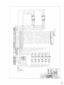
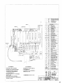
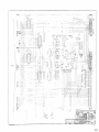
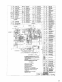
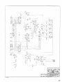
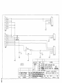
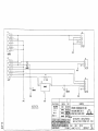
The output of the battery comparator is taken at V2 pin 7, routed through a voltage divider network
ofR25 and R26 to P2-12 where it is used to generate a processor interrupt in the oximeter processor
assembly. Diode D31 is used to clamp the -12 VDC low output of the comparator to a ground level
for input to the processor logic circuits. C32 and C48 provide noise immunity at the comparator
crossover point. Note that the unregulated DC input overrides the battery input when AC line power
is applied to the oximeter. R28 and D32 are active when external power is applied to prevent
spurious low battery warnings. A microprocessor shutdown input is provided at P2 pin 6 allowing
external control of switching regulator VI pin 10. When a shutdown signal is received at P2 pin 6
it is routed through D21 to P2 pin 14 where it is used to generate hardware reset signals by the
oximeter processor. When the oximeter power switch is depressed positive voltage generated at P2
pin 11 is also routed through R6 to P2 pin 13 where it is sent to an input port on the processor
assembly. This signal is monitored periodically by the processor and when high (+5 VDC) is used
to initiate a processor controlled shutdown of the power supply. R5 is a pull-down resistor to insure
the signal is low when the external power switch is not depressed.
2-16