1
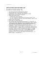
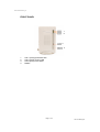
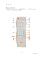
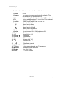
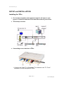
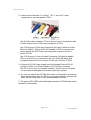
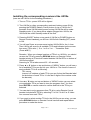
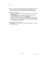
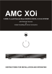
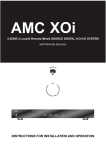
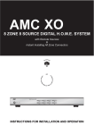
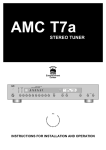
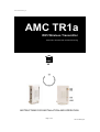
User manual-amc TR1a_G
AMC TR1a
WiFi Wireless Transmitter
with Video On Demand and Broadcasting
AMC
TM
HOME
IA
Entertainment
Center
INSTRUCTIONS FOR INSTALLATION AND OPERATION
Page 1 of 17
PN: 21-TR1a_IM
User manual-amc TR1a_G
Page 2 of 17
PN: 21-TR1a_IM
User manual-amc TR1a_G
APPLICATION AND FEATURE LIST
FEATURES OF THE AMCTM MODEL TR1a
•
•
•
•
•
•
•
•
•
with Video on Demand and Broadcasting features.
Wireless IEEE 802.11a 5 GHz Wifi configuration.
Internal NTSC / PAL or SECAM / PAL dual band TV Tuner
Multiple audio and video inputs supported.
Three external Video Inputs :
S VIDEO input : one S connector
AV1 input: Composite Video(three RCA Connectors- Video, L & R)
AV2 input: Composite Video( one 3.5mm Mini connector– Video, L & R)
MPEG II video chip Encoder
Video Scaler : 3D video image chip
The receiving units must be within approximately 65 - 100 feet (20 – 30
meters) of the TR1a to send and receive transmissions clearly. However,
this distance will vary, depending on the surroundings. At home, it is
best to set up the base station in a central location, allowing more even
distribution of the wireless signal to all parts of the house.
Accessories: Stand x 1,Power Adaptor x 1 (Input: 100~240VAC 1.0A
max 20~30VA 50/60Hz, Output: 12VDC 1.0A 12W max) , Remote Control
x 1, RCA AV Cable x 1 (for AV1 composite Video input)(3 RCA Plugs to 3
RCA plugs), 3.5mm mini jack to 3 RCA plugs AV Cable x 1 ( for AV2
composite Video input), S-video cable x 1 (For S VIDEO input)(Audio
inputs of S VIDEO input are common use with Audio input RCA
connectors of AV1), TV Tuner input adaptor, External Antenna x 1, IR
Blaster Cable x 1, User Manual x 1,
Page 3 of 17
PN: 21-TR1a_IM
User manual-amc TR1a_G
REAR & FRONT SIDE PANELS / FRONT PANEL
REAR & FRONT SIDE PANELS
Rear Side Panel
10
1.
2.
3.
4.
5.
“RJ-45”
“DC 12V” power input connector
“OFF/ON” Power Switch
“S VIDEO” input connector
“AV1” Composite Video input
RCA connector (Yellow)
6. “AV1” Audio L input
RCA connector (White)
7. “AV1” Audio R input
RCA connector (Red)
8. “AV2” Composite Video input
3.5mm mini connector(Video, L, R)
9. “TV Tuner” input connector
10. WiFi External Antenna
Front Side Panel
1
Connector for IR Blaster
2
Pre-Out
1.
2.
Connector for IR Blaster
Connector for Stereo Audio Pre-Out (option)
Page 4 of 17
PN: 21-TR1a_IM
User manual-amc TR1a_G
FRONT PANEL
1
2
3
4
1.
2.
3.
4.
LED 1 (Orange) Wireless LED
LED 2 (Green) Power LED
LED 3 (Red) Tuner Status
RESET
Page 5 of 17
PN: 21-TR1a_IM
User manual-amc TR1a_G
REAR SIDE PANEL
1. RJ-45
The RJ45 is for updating firmware of
TR1a or hooking TR1a to Ethernet
Network for Linking TR1a to all other
equipment with IP addresses linked
to the Ethernet Network.
2. “DC 12V” power input
connector
This DC 12V power input connector
is for connecting 12VDC power from
TR1a Power Adaptor to the TR1a.
3. “OFF / ON” Power Switch
Slide the switch to left hand side will
turn the power of TR1a OFF. Slide
the switch to right hand side will turn
the power if the TR1a ON.
This is Audio R input RCA connector
(Red) for AV1 for hooking to
Composite Sources.
8. “AV2” Composite Video input
3.5mm mini connector
(Video, L, R)
This is a 3.5mm mini connector with
Video, L, R for Composite Video
“AV2” input for hooking to Composite
Sources.
9. “TV Tuner” input connector
This is a connector for hooking to TV
Antenna or Cable TV's.
4. “S VIDEO” input connector
This is an input connector for “S
VIDEO” sources.
5. “AV1” Composite Video input
RCA connector (Yellow)
This is Composite Video input RCA
connector (Yellow) for AV1 for
hooking to Composite Sources.
10. WiFi External Antenna
This connector is for hooking to
external 5GHz 802.11a WiFi
Antenna.
6. “AV1” Audio L input
RCA connector (White)
This is Audio L input RCA connector
(White) for AV1 for hooking to
Composite Sources.
7. “AV1” Audio R input
RCA connector (Red)
Page 6 of 17
PN: 21-TR1a_IM
User manual-amc TR1a_G
FRONT SIDE PANEL
1. Connector for IR Blaster
The 3.5mm mini connector is for IR
Blaster Output. IR Blasters can be
hooked up to the connector.
2. Connector for Stereo Audio
Pre-Out (Option)
The 3.5mm mini connector is for
Stereo Audio Pre-Out. The Pre-Out
is for connecting to external Stereo
Audio systems and the latency
between the Pre-Out and Video will
have to be adjusted by time delay
module. So, the Pre-Out is an option
and will be installed for special
designed projects and according to
special orders only.
FRONT PANEL
1. LED 1 (Orange) Wireless LED
Blinking slowly : wireless is
connecting
Blinking quickly : wireless is
connected and transmitting data
2. LED 2 (Green) Power LED
This is a Power On LED.
you can use the switch to reset TR1a
by following procedure,
a. Switch off the TR1a
b. Press and hold the reset button
and then switch on TR1a
c. Wait for 5 seconds and then
release the reset button.
d. the TR1a should have then been
reset to factory default setup.
3. LED 3 (Red) Tuner Status
Tuner Initialization Confirmed
4. RESET
This is a switch to reset TR1a.
When TR1a experiences unstable
operation or trouble for connecting,
Page 7 of 17
PN: 21-TR1a_IM
User manual-amc TR1a_G
Remote Control
(for using with receiving units like AMC i-M15a to control TR1a through IR
receiver on receiving units and WiFi )
AMC
Page 8 of 17
PN: 21-TR1a_IM
User manual-amc TR1a_G
Function of each button on Remote Control Handset:
1. Power
2. Rescan
3. Video
4. TV
5. Audio
6. Screen
7. ▲
▼
Menu
►
◄
8. Mute
9. Saving
10. Display
11. 1~9
12. Volume ▲
13. Volume ▼
14. Channel ▲
15. 100
16.
0
17. ◄
18. Channel ▼
19. TV Scan
20. Wireless
21. Bitrate
22. Enter
On/Off
for receiver to re-scan and locate all available TR1a
and can select one preferable TR1a.
Select AV1, AV2 or S-video input of the TR1a selected
Select Cable/Broadcast TV input of the TR1a selected
STEREO, SAP, MONO
Select Display aspect ratio 16:10 or 4:3
Menu function up
Menu function down
Menu function display
Menu function forward
Menu function backward
Audio Mute On/Off
On (brightness 80%) / Off (brightness 45%)
Display and language selection
Numeric Keys 1~9
Volume up
Volume down
TV channel up
Numeric Key 100
Numeric Key 0
Recall last channel
TV channel down
Auto-detect channels with TV programs
Wireless channel selection
Low, Mid, High
Function confirm
Page 9 of 17
PN: 21-TR1a_IM
User manual-amc TR1a_G
SETUP and INSTALLATION
Installing the TR1a
z
For the best reception of the wireless signal to all areas of your
house, it is best to install the TR1a near the center of your house.
z
TR1a setup overview
z
Connecting source devices to TR1a
1. Connect the Cable TV or Broadcast TV Antenna to the “TV Tuner”
connector on rear side panel of TR1a
Page 10 of 17
PN: 21-TR1a_IM
User manual-amc TR1a_G
2. Connect source devices to “S-Video”, “AV-1” and “AV-2” input
connectors on rear side panel of TR1a
Use S-Video cable included in TR1a to connect your source device with
S-Video output to the S Video input connector of TR1a.
Use 3 RCA plug to 3 RCA plug Composite AV cable (Yellow for Video,
White for Audio-L, Red for Audio-R) included in TR1a to connect your
source device like DVD Player with Composite outputs to the AV1
inputs of TR1a.
Use 3 RCA plug to 3.5mm mini jack Composite AV Cable included in
TR1a to connect your source device like your 2nd DVD player with
Composite outputs to the AV2 input (3.5mm mini AV jack) of TR1a.
3. Connect to DC12V Power supply and LAN through Ethernet RJ-45.
Connect 12VDC/ 1.0A Power Adaptor to DC12V input connector.
The RJ-45 on TR1a is for firmware updating. This function is an option
for each special designed LAN as each proprietary system.
4. You now can switch the OFF/ON slide switch to ON position and start to
enjoy the programs from the TR1a you just setup through receivers like
AMC i-M15a, computers or other corresponding receivers.
5. The power LED (LED2) should be lighted once the OFF/ON slide switch
switched to ON position
Page 11 of 17
PN: 21-TR1a_IM
User manual-amc TR1a_G
Installing the corresponding receivers like i-M15a
(here we use i-M15a for the installing procedures )
1. Turn on TR1a – power LED will be lighted
2. Turn i-M15a (or other corresponding receivers) battery power ON by
pressing the POWER (Battery Power) button on top of i-M15a for 5
seconds. Once i-M15a battery power turning ON i-M15a will be under
Standby mode. (If you have power adaptor plugged into i-M15a, the
i-M15a will be under Standby mode all the time.
3. Pressing ON/OFF button on top panel of i-M15a (or POWER button on
Remote Control handset) you will turn i-M15a from Standby(OFF) mode
to ON.
4. You will see Power on screen once turning i-M15a ON for the 1st time.
Then i-M15a will scan for all available TR1a and indicated on the screen
how many TR1a exist. (“ 0 or 1 or 2 or 3 or .... Transmitter Exist .
(Press ▲/▼)” )
Remarks : When you change locations of TR1a's or i-M15a's, you should
re-scan the TR1a by pressing RESCAN button on Remote Control
handset aiming at IR receiver located besides i-M15a LED's on bottom of
i-M15a front panel.
Scanning for TR1a takes around 25 ~ 40 seconds.
5. Press ▲ or ▼ button on top and bottom of “MENU” button, you will see a
list of available TR1a you can link your i-M15a to. The format of name of
each available TR1a is as following:
TR1-xxxxxx
(xxxxxx is IP address of each TR1a you can find on the Barcode label
on the bottom of each TR1a. It is the last 6 digits of the number under
the barcode)
6. Use ▲ or ▼ button on top and bottom of “MENU” button you can select
your preferable TR1a you want to view the programs from. You then
press ENTER on remote control to confirm and link to the TR1a you
selected.
7. You can start to enjoy programs from TR1a by using Remote Control
handset included with TR1a by selecting TV or AV1 or AV2 or S-Video
four sources from each TR1a.
8. If you want to select another TR1a for the i-M15a you are using, you can
press RESCAN button on Remote Control hand set and repeat above
procedure to make the choice.
Page 12 of 17
PN: 21-TR1a_IM
User manual-amc TR1a_G
9. When one i-M15a selected a TR1a and other i-M15a's want to connect to
the same TR1a, the other i-M15a's will be under LISTENING mode.
And the TR1a will be only controlled by the 1st i-M15a connected to it.
10. Scanning in TV Channels
a. Press the TV button on the remote to select between “Broadcast TV”
and “Cable TV”
b. Press TV SCAN button on the remote and choose your local TV
system by pressing “TV SCAN” button in sequence.
c. After choosing your TV system, press ENTER on the remote, the TV
Tuner in TR1a will automatically scan and save all available channels.
d. Now you can enjoy TV programs on your i-T15a by using the remote
handset similar to normal TV set.
11. Selecting AV1, AV2 and S-Video
Press VIDEO button on remote, you will be able to select AV1 or AV2 or
S-Video input source.
Page 13 of 17
PN: 21-TR1a_IM
User manual-amc TR1a_G
Page 14 of 17
PN: 21-TR1a_IM
User manual-amc TR1a_G
SPECIFICATIONS
Wireless ............... IEEE 802.11a 5 GHz
Video Encoder .....
MPEG2 video chip, DVD Quality
Video Scaler ........
3D video image chip
with Video on Demand and Broadcasting features
Wireless IEEE 802.11a 5 GHz Wifi configuration
Internal NTSC / PAL or SECAM / PAL dual band TV Tuner
Three external Video Inputs :
S VIDEO input : one S connector
AV1 input: Composite Video(three RCA Connectors- Video, L & R)
AV2 input: Composite Video( one 3.5mm Mini connector– Video, L & R)
MPEG II video chip Encoder
PHYSICAL
Dimensions (W x H x D) .........................................................
125x232x32 mm
Net weight (embedded Antenna) ......................................................... 500 gm
Shipping weight (4 pieces).....................................................................
Power consumption............................................................................
Kgs
Max12 W
Input Power–Input power to Power Adaptor... 20~30VA,100~240VAC,50/60Hz
Max Power output from Power Adaptor ...........................
12W (12 VDC / 1A)
Weltronics Corp. reserved the right to improve its products at any time.
Specifications are subject to change without notice.
Page 15 of 17
PN: 21-TR1a_IM
User manual-amc TR1a_G
Page 16 of 17
PN: 21-TR1a_IM
User manual-amc TR1a_G
WELTRONICS CORP.
LONDON/L.A.
AMC Web: http://www.amchome.com
PN: 21-TR1a_IM
Page 17 of 17
PN: 21-TR1a_IM