1
AMC TR1a
WiFi Wireless Transmitter
with Video On Demand and Broadcasting
IA
CAUTIONS AND FEATURE LIST
FEATURES OF THE AMCTM MODEL TR1a
* with Video on Demand and Broadcasting features.
* Wireless IEEE 802.11a 5 GHz WiFi configuration.
* Internal NTSC / PAL or SECAM / PAL dual band TV Tuner.
* Multiple audio and video inputs supported.
* Three external Video Inputs :
S VIDEO input: one S connector
AV1 input: Composite Video (three RCA Connectors - Video, L & R)
AV2 input: Composite Video (one 3.5mm Mini connector - Video, L & R)
* MPEG II video chip Encoder
* Video Scaler: 3D video image chip
* The receiving units must be within approximately 65 - 100 feet (20 - 30 meters) of
the TR1a to send and receive transmissions clearly. However, this distance will
vary, depending on the surroundings. At home, it is best to set up the base station in
a central location, allowing more even distribution of the wireless signal to all parts
of the house.
* Accessories: Stand x 1,Power Adaptor x 1 (Input: 100~240VAC 1.0A max 20~30VA
50/60Hz, Output: 12VDC 1.0A 12W max) , Remote Control x 1, RCA AV Cable x 1
(for AV1 composite Video input) (3 RCA plugs to 3 RCA plugs), 3.5mm mini jack to 3
RCA plugs AV Cable x 1 ( for AV2 composite Video input), S-video cable x 1 (For S
VIDEO input) (Audio inputs of S VIDEO input are common use with Audio input
RCA connectors of AV1), TV Tuner input adaptor, External Antenna x 1, IR Blaster
Cable x 1, User Manual x 1.
2
REAR & FRONT SIDE PANELS / FRONT PANEL
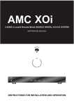
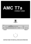
REAR & FRONT SIDE PANELS
10
1.
2.
3.
4.
5.
6.
7.
8.
9.
10.
1
2
3
5
4
6
7 8
9
"RJ-45"
"DC 12V" power input connector RCA connector (Red)
"OFF/ON" Power Switch
"S VIDEO" input connector 3.5mm mini connector(Video, L, R)
"AV1" Composite Video inpu
RCA connector (Yellow)
"AV1" Audio L input
RCA connector (White)
"AV1" Audio R input
RCA connector (Red)
"AV2" Composite Video input
3.5mm mini connector(Video, L, R)
"TV Tuner" input connector
WiFi External Antenna
FRONT SIDE PANEL
1
2
1. Connector for IR Blaster
2. Connector for Stereo Audio Pre-Out (option)
3
FRONT PANEL
1
2
3
4
1.
2.
3.
4.
LED 1 (Orange) Wireless LED
LED 2 (Green) Power LED
LED 3 (Red) Tuner Status
RESET
4
FREAR SIDE PANEL
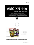
1. RJ-45
The RJ45 is for updating firmware of
TR1a or hooking TR1a to Ethernet
Network for linking TR1a to all other
equipment with IP addresses linked to the
Ethernet Network.
8. " AV 2 " C o m p o s i t e V i d e o i n p u t
3.5mm mini connector (Video, L, R)
This is a 3.5mm mini connector with
Video, L, R for Composite Video "AV2"
input for hooking to Composite Sources.
9. "TV Tuner" input connector
This is a connector for hooking to TV
Antenna or Cable TV's.
2. "DC 12V" power input connector
This DC 12V power input connector is for
connecting 12VDC power from TR1a
Power Adaptor to the TR1a.
3. "OFF / ON" Power Switch
Slide the switch to left hand side will turn
the power of TR1a OFF. Slide the switch
to right hand side will turn the power if the
TR1a ON.
4. "S VIDEO" input connector
This is an input connector for "S VIDEO"
sources.
5. "AV1" Composite Video input RCA
connector (Yellow)
This is Composite Video input RCA
connector (Yellow) for AV1 for hooking to
Composite Sources.
10.WiFi External Antenna
This connector is for hooking to external
5GHz 802.11a WiFi Antenna.
6. "AV1" Audio L input RCA connector
(White)
This is Audio L input RCA connector
(White) for AV1 for hooking to Composite
Sources.
7. "AV1" Audio R input RCA connector
(Red)
This is Audio R input RCA connector
(Red) for AV1 for hooking to Composite
Sources.
5
FRONT SIDE PANEL
1. Connector for IR Blaster
The 3.5mm mini connector is for IR
Blaster Output. IR Blasters can be
hooked up to the connector.
connecting to external Stereo Audio
systems and the latency between the
P r e - O u t a n d Vi d e o w i l l h a v e t o b e
adjusted by time delay module. So, the
Pre-Out is an option and will be installed
for special designed projects and
according to special orders only.
2. Connector for Stereo Audio Pre-Out
(Option)
The 3.5mm mini connector is for Stereo
Audio Pre-Out. The Pre-Out is for
FRONT PANEL
you can use the switch to reset TR1a by
following procedure,
a. Switch off the TR1a
b. Press and hold the reset button and
then switch on TR1a
c. Wait for 5 seconds and then release
the reset button.
d. the TR1a should have then been reset
to factory default setup.
1. LED 1 (Orange) Wireless LED
Blinking slowly : wireless is connecting
Blinking quickly : wireless is connected
and transmitting data.
2. LED 2 (Green) Power LED
This is a Power On LED.
3. LED 3 (Red) Tuner Status
Tuner Initialization Confirmed
4. RESET
This is a switch to reset TR1a. When
TR1a experiences unstable operation or
trouble for connecting,
6
REMOTE CONTROL
(for using with receiving units like AMC i-M15a to control TR1a through IR receiver on
receiving units and WiFi)
3
1
4
2
5
6
8
7
9
10
12
11
13
14
15
18
16
17
19
22
20
21
7
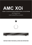
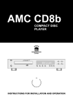
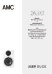
Function of each button on Remote Control Handset:
1. Power
On/Off
2. Rescan
for receiver to re-scan and locate all available TR1a
select one preferable TR1a.
3. Video
Select AV1, AV2 or S VIDEO input of the TR1a selected
4. TV
Select Cable/Broadcast TV input of the TR1a selected
5. Audio
STEREO, SAP, MONO
6. Screen
Select Display aspect ratio 16:10 or 4:3
7.
Menu function up
Menu function down
Menu function display
Menu function forward
Menu function backward
Menu
and can
8. Mute
Audio Mute On/Off
9. Savings
(same as remote key printing, actually this is "OUTDOOR" mode
selection key)
On (brightness 80%) / Off (brightness 45%) ->
Outdoor (brightness 85%) / Normal (brightness 45%)
The i-M15a screen will be in black when i-M15a battery power is
too low to support higher brightness
10. Display
Display and language selection
11. 1~9
Numeric Keys 1~9
12. Volume
Volume up
13. Volume
Volume down
14. Channel
TV channel up
15. 100
Numeric Key 100
16. 0
Numeric Key 0
17.
Recall last channel
18. Channel
TV channel down
8
19. TV Scan
Auto-detect channels with TV programs
20. Wireless
Wireless channel selection
21. Bitrate
Low, Mid, High
22. Enter
Function confirm
9
SETUP AND INSTALLATION
Installing the TR1a
For the best reception of the wireless signal to all areas of your house, it is best
to install the TR1a near the center of your house.
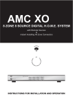
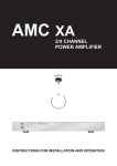
TR1a setup overview
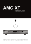
Connecting source devices to TR1a
3
2
1
10
1. Connect the Cable TV or Broadcast TV Antenna to the "TV Tuner" connector on
rear side panel of TR1a
2. Connect source devices to "S VIDEO", "AV1" and "AV2" input connectors on rear
side panel of TR1a
S VIDEO
AV1
(DVD-1)
AV2 (Mini AV)
DVD-2
Use S-Video cable included in TR1a to connect your source device with S-Video
output to the S Video input connector of TR1a.
Use 3 RCA plug to 3 RCA plug Composite AV cable (Yellow for Video, White for
Audio-L, Red for Audio-R) included in TR1a to connect your source device like DVD
Player with Composite outputs to the AV1 inputs of TR1a.
Use 3 RCA plug to 3.5mm mini jack Composite AV Cable included in TR1a to
connect your source device like your 2nd DVD player with Composite outputs to the
AV2 input (3.5mm mini AV jack) of TR1a.
3. Connect to DC12V Power supply and LAN through Ethernet RJ-45. Connect
12VDC/ 1.0A Power Adaptor to DC12V input connector. The RJ-45 on TR1a is for
firmware updating. This function is an option for each special designed LAN as
each proprietary system.
4. You now can switch the OFF/ON slide switch to ON position and start to enjoy the
programs from the TR1a you just setup through receivers like AMC i-M15a,
computers or other corresponding receivers.
5. The power LED (LED2) should be lighted once the OFF/ON slide switch switched to
ON position
11
INSTALLING THE CORRESPONDING RECEIVERS LIKE i-M15a
(here we use i-M15a for the installing procedures )
1. Turn on TR1a
power LED will be lighted
2. Turn i-M15a (or other corresponding receivers) battery power ON by pressing the
POWER (Battery Power) button on top of i-M15a for 5 seconds. Once i-M15a
battery power turning ON i-M15a will be under Standby mode. (If you have power
adaptor plugged into i-M15a, the i-M15a will be under Standby mode all the time.
3. Pressing ON/OFF button on top panel of i-M15a (or POWER button on Remote
Control handset) you will turn i-M15a from Standby(OFF) mode to ON.
4. You will see Power on screen once turning i-M15a ON for the 1st time. Then iM15a will scan for all available TR1a and indicated on the screen how many TR1a
exist. (" 0 or 1 or 2 or 3 or .... Transmitter Exist . (Press
/
)" )
Remarks : When you change locations of TR1a's or i-M15a's, you should re-scan
the TR1a by pressing RESCAN button on Remote Control handset aiming at IR
receiver located besides i-M15a LED's on bottom of i-M15a front panel. Scanning
for TR1a takes around 25 ~ 40 seconds.
5. Press
or
button on top and bottom of "MENU" button, you will see a list of
available TR1a you can link your i-M15a to. The format of name of each available
TR1a is as following:
TR1-xxxxxx (xxxxxx is IP address of each TR1a you can find on the Barcode label
on the bottom of each TR1a. It is the last 6 digits of the number under the
barcode)
6. Use
or
button on top and bottom of "MENU" button you can select your
preferable TR1a you want to view the programs from. You then press ENTER on
remote control to confirm and link to the TR1a you selected.
7. You can start to enjoy programs from TR1a by using Remote Control handset
included with TR1a by selecting TV or AV1 or AV2 or S VIDEO four sources from
each TR1a.
8. If you want to select another TR1a for the i-M15a you are using, you can press
RESCAN button on Remote Control hand set and repeat above procedure to
make the choice.
9. When one i-M15a selected a TR1a and other i-M15a's want to connect to the
same TR1a, the other i-M15a's will be under LISTENING mode. And the TR1a will
be only controlled by the 1st i-M15a connected to it.
10. Scanning in TV Channels
a. Press the TV button on the remote to select between "Broadcast TV" and
"Cable TV"
12
b. Press TV SCAN button on the remote and choose your local TV system by
pressing "TV SCAN" button in sequence.
c. After choosing your TV system, press ENTER on the remote, the TV Tuner in
TR1a will automatically scan and save all available channels.
d. Now you can enjoy TV programs on your i-M15a by using the remote handset
similar to normal TV set.
11. Selecting AV1, AV2 and S VIDEO
Press VIDEO button on remote, you will be able to select AV1 or AV2 or S VIDEO
input source.
13
Video On Demand and Broadcasting
14
SPECIFICATIONS
Wireless . . . . . . . . . . . . . . . . . . . . . . . . . . . . . . . . . . . . . . . . . . . . . IEEE 802.11a 5 GHz
Video Encoder . . . . . . . . . . . . . . . . . . . . . . . . . . . . . . MPEG2 video chip, DVD Quality
Video Scaler . . . . . . . . . . . . . . . . . . . . . . . . . . . . . . . . . . . . . . . . . 3D video image chip
with Video on Demand and Broadcasting features
Wireless IEEE 802.11a 5 GHz Wifi configuration
Internal NTSC / PAL or SECAM / PAL dual band TV Tuner
Three external Video Inputs :
S VIDEO input : one S connector
AV1 input: Composite Video(three RCA Connectors- Video, L & R)
AV2 input: Composite Video( one 3.5mm Mini connector Video, L & R)
MPEG II video chip Encoder
PHYSICAL
Dimensions (W x H x D) . . . . . . . . . . . . . . . . . . . . . . . . . . . . . . . . . . . 125x232x32 mm
Net weight (embedded Antenna) . . . . . . . . . . . . . . . . . . . . . . . . . . . . . . . . . . . . 2.3Kgs
Shipping weight (8 pieces) . . . . . . . . . . . . . . . . . . . . . . . . . . . . . . . . . . . . . . . . 19.8 Kgs
Power consumption . . . . . . . . . . . . . . . . . . . . . . . . . . . . . . . . . . . . . . . . . . . . . Max12 W
Input Power Input power to Power Adaptor . . . . . . . 20~30VA,100~240VAC,50/60Hz
Max Power output from Power Adaptor . . . . . . . . . . . . . . . . . . . . . . 12W (12 VDC / 1A)
Weltronics Corp. reserved the right to improve its products at any time. Specifications
are subject to change without notice.
15
SAFETY INSTRUCTION
1. READ INSTRUCTIONS
16. DAMAGE REQUIRING SERVICE
All the safety and operating instructions should be read
before the appliance is operated.
2. RETAIN INSTRUCTIONS
The safety and operating instructions should be retained for
future reference.
3. HEED WARNINGS
All warnings on the appliance and in the operating instructions
should be adhered to.
4. FOLLOW INSTRUCTIONS
All operating and use instructions should be followed.
The appliance should not be used near water - for example,
near a bathtub, washbowl, kitchen sink, laundry tub, in a wet
basement, or near a swimming pool, etc.
6. CARTS AND STANDS
The appliance should be used only with a cart or stand that is
recommended by the manufacturer.
7. WALL OR CEILING MOUNTING
17. POWER LINES
(APPLIES TO TUNER AND RECEIVERS ONLY)
An outdoor antenna should be located away from power lines.
5. WATER AND MOISTURE
6A. An appliance and cart combination should be
moved with care. Quick stops, excessive force,
and uneven surfaces may cause the appliance
and cart combination to overturn.
The appliance should be serviced by qualified service
personnel when:
a) The power-supply cord or the plug has been damaged; or
b) Objects have fallen, or liquid has been spilled into the
appliance; or
c) The appliance has been exposed to rain; or
d) The appliance does not appear to operate normally or
exhibits a marked change in performance; or
e) The appliance has been dropped, or the enclosure is
damaged.
PORTABLE CART WARNING
S3125A
This equipment is not designed for use mounted on a wall or a
ceiling.
8. VENTILATION
The appliance should be situated so that its location or position
does not interfere with its proper ventilation. For example, the
appliance should not be situated on a bed, sofa, rug, or similar
surface that may block the ventilation openings, or placed in a
built-in installation, such as bookcase or cabinet that may
impede the flow of air through the ventilation openings.
9. HEAT
The appliance should be situated away from heat sources
such as radiators, heat registers, stoves, or other appliances
(including amplifiers) that produce heat.
18. OUTDOOR ANTENNA GROUNDING
(APPLIES TO TUNER AND RECEIVERS ONLY)
If an outside antenna is connected to the receiver, be sure the
antenna system is grounded so as to provide some protection
against voltage surges and built up static charges.
Section 810 of the National Electrical Code, ANSI/NFPA No.
70-1984, provides information with respect to proper
grounding of the mast and supporting structure, grounding of
the lead-in wire to an antenna discharge unit, size of grounding
conductors, location of antenna-discharge unit, connection to
grounding electrodes, and requirements for the grounding
electrode. See Figure.
a) Use No. 10 AWG (5.3 mm2) copper, No. 8 AWG (8.4 mm2)
aluminum, No. 17 AWG (1.0 mm2) copper-clad steel or
bronze wire, or larger, as a ground wire.
b) Secure antenna lead-in and ground wires to house with
stand-off insulators spaced from 4-6 feet (1.22-1.83 m)
apart.
c) Mount antenna discharge unit as close as possible to where
lead-in enters house.
d) Use jumper wire not smaller than No.6 AWG (13.3 mm2)
copper, or the equivalent, when a separate antennagrounding electrode is used. See NEC Section 810-21(j).
Antenna Grounding According to
the National Electrical Code
10. POWER SOURCES
The appliance should be connected to a power supply only of
the type described in the operating instructions or as marked
on the appliance.
Antenna Lead
In Wire
11. POWER-CORD PROTECTION
Power-supply cords should be routed so that they are not likely
to be walked on or pinched by items placed upon or against
them, paying particular attention to cords at plugs,
convenience receptacles, and the point where they exit from
the appliance
12. CLEANING
The appliance should be cleaned only as recommended by
the manufacturer.
Ground
Clamp
Electric
Service
Equipment
The power cord of the appliance should be unplugged from the
outlet when left unused for a long period of time.
Power Service Grounding
Electrode System
(NEC Art 250 Part H)
14. OBJECT AND LIQUID ENTRY
15. SERVICING
The user should not attempt to service the appliance beyond
that described in the operating instructions. All other servicing
should be referred to qualified service personnel.
Grounding Conductors
(NEC Section 810.21)
Ground Clamps
13. NON USE PERIODS
Care should be taken so that objects do not fall and liquids are
not spilled into the enclosure through openings.
Antenna
Discharge
Unit (NEC
Section 810.20)
National Electrical Code
Available from Library, book
stores, or National Fire Protection
Association (Batterymarch Park,
Quincy. MA 02269).
AMC 21-3004
WELTRONICS CORP.
LONDON/L.A.
AMC Web: http://www.amchome.com
PN: 21R-4210