1
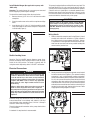
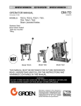
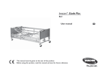
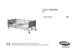
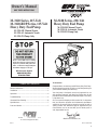
Owner’s Manual
SAVE THESE INSTRUCTIONS
M-3120 Series, 115-Volt
M-3120-RDP Series, 115-Volt
Heavy Duty Fuel Pump
M-3120-ML Manual Nozzle
M-3120-AL Automatic Nozzle
M-3120-PO Pump Only
M-3220 Series, 230-Volt
Heavy Duty Fuel Pump
M-3220-ML Manual Nozzle
M-3220-AL Automatic Nozzle
M-3220-PO Pump Only
Please contact GPI before returning
any product. If you are missing parts or
experience problems with your installation, our Customer Support Department will be happy to assist you.
GPI Customer Support
800-835-0113 or
316-686-7361
TABLE OF CONTENTS
General Information................................................................2
Installation..............................................................................2
Operation................................................................................4
Troubleshooting......................................................................5
Illustrated Parts Drawing........................................................6
To the owner...
Congratulations on receiving your GPI Heavy Duty Fuel Pump.
We are pleased to provide you with a system designed to give
you maximum reliability and efficiency.
Your fuel pump is designed, tested, and approved for use
with gasoline, kerosene, and diesel fuel. Please take all due
precautions when handling these flammable liquids. Your safety
is important to us.
Parts and Service...................................................................7
Also, to assure the longest possible service life, it is important
that you follow the operation and maintenance procedures
outlined in this manual. We are proud to provide you with a
quality product and dedicated support. Together with your
conscientious use, we are sure that you will obtain years of
safe, dependable service.
Great Plains Industries, Inc. is a member of
the Petroleum Equipment Institute.
President
Great Plains Industries, Inc.
Specifications.........................................................................7
05/11
Rev. D 921927-04
1
GENERAL INFORMATION
There are inherent dangers wherever flammable fuel and AC
electrical sources are in close proximity.
Your pump is designed for use only with thin viscosity petroleum
fuels such as gasoline (up to 15% alcohol blends such as
E15), diesel fuel (up to 20% biodiesel blends such as B20) and
kerosene. Do not use this pump for dispensing any fluids other
than those for which it was designed. Using the pump with
other fuels can damage components and void the warranty.
Static electricity as a source of sparking is always a concern
and requires extreme care in the installation and operation of
your entire fuel transfer system.
Model Components
Additional components such as meters, automatic nozzles
and filters must be listed for use with fuel transfer systems.
The flow of fuel through a hose and nozzle can generate static
electrical charges and dangerous sparking can result in fire or
explosion. Hoses and nozzles must be electrically conductive
and bonded to ground.
M-3120-ML / M-3220-ML: Includes pump, hose, manual nozzle
and components to assemble to unit before use.
It is your responsibility to:
•
M-3120-PO / M-3220-PO: Includes pump only and components to assemble to unit before use.
Know and follow applicable national, state and local safety
codes pertaining to installing and operating electrical
equipment for use with flammable liquids.
•
M-3120-RDP: Includes dedicated pump only for remote dispensing systems.
Know and follow all safety precautions when handling
petroleum fuels.
•
Ensure that all equipment operators have access to
adequate instructions concerning safe operating and
maintenance procedures.
M-3120-AL / M-3220-AL: Includes pump, hose, automatic
nozzle and components to assemble to unit before use.
NOTE: Suffixes ML, AL and PO are for ordering purposes only.
Constructions described above are covered as alternate
constructions under the Part No. M-3120 and M-3220
UL Listing.
How to Use This Manual
The purpose of this manual is to assist you in installing, operating and maintaining your GPI pump. If you need additional
assistance, contact your GPI dealer or the GPI Customer
Service Department.
The following safety alert symbols are used
in this manual. Obey all safety messages
that follow this symbol to avoid possible
injury or death.
DANGER
WARNING
CAUTION
CAUTION
2
DANGER indicates an
imminently hazardous
situation which, if not
avoided, will result in
death or serious injury.
WARNING indicates a
potentially hazardous
situation which, if not
avoided, could result in
death or serious injury.
CAUTION indicates a
potentially hazardous
situation which, if not
avoided, may result in
minor or moderate injury.
CAUTION used without
the safety alert symbol
indicates a potentially
hazardous situation which,
if not avoided, may result
in property damage.
INSTALLATION
WARNING
Coverplates protect the operator from moving parts. Never
operate the pump without coverplates in place. Never apply
electric power to the pump without coverplates in place.
Always disconnect power before repairing or servicing.
Mechanical Connections
All threaded fuel connections must be sealed with thread tape
or a pipe thread sealing compound approved for use with
petroleum fuels and tightened securely to prevent leakage.
For 3/4 inch applications, Part No. 111018-1 Bushing is used.
See Item 42 in parts drawing for reference.
Your pump must be mounted on a vented tank. If the tank is not
vented, contact your GPI distributor for the correct vent cap.
This pump has a built-in check valve to keep the pump primed.
No additional check valve is required on suction pipes shorter
than 15 feet (4.6 meters). Make sure any check valves or foot
valves used are equipped with proper pressure relief valves.
Your pump is designed to mount directly to a standard 2-inch
female tank fitting. For the suction pipe, a 1-inch galvanized
steel pipe cut to length and threaded on one end may be used.
Suction pipe should extend to within 3 inches of tank bottom.
Apply thread tape to the suction pipe thread and securely
tighten the suction pipe to the pump inlet port.
Install Nozzle Hanger (Not applicable to pumps with
-RDP suffix)
Attention: The nozzle hanger for your pump was removed
before shipping to protect against damage.
To reinstall the nozzle hanger follow the steps below.
1. Remove the two (2) 1/4"-20 x 1/2" bolts from the switch
coverplate.
2. Place the nozzle cover on the switch coverplate and align
holes.
3. Insert the two (2) 1/4"-20 x 1/2" bolts through the nozzle
cover and thread into the switch coverplate. Torque bolts
to 45-60 in/lb (Figure 1).
This pump is equipped with an auxiliary AC accessory lead. The
third wire (brown for 115-volt system and purple for 230-volt
system) is to be used to energize a control circuit that operates
a device such as a signal light or a solenoid operated valve.
Maximum amp draw on the control circuit is 1 amp. If you do
not need this feature, ensure that the wire is insulated and
enclosed within the electrical cavity of the pump.
CAUTION
Connect pump to the proper voltage source. M-3120
Series Pumps are designed to operate on 115 VAC, 60 Hz.
M-3220 Series Pumps are designed to operate on 220240 VAC, 50/60 Hz. Connection to improper voltage will
damage pump.
Figure 1
Wiring Details
1. Remove electrical coverplate and O-ring (Figure 2). Install
conduit and cable from switchbox to pump electrical
box. Wiring must be in accordance with Class I, Division
1 requirements in the applicable national electrical code.
Note that the lead wires are factory-sealed isolating the
motor from the junction box.
Figure 2
Switch Locking Lever
Attention: The M-3120-RDP remote dispenser pump incorporates an external switch locking lever that locks the pump
switch in the “ON” position. The pump is typically shut off
using the remote dispensing device “ON-OFF” mechanism.
Electrical Connections
DANGER
Pump must be installed by a licensed electrician and
conform to National Fire Protection Association (NFPA)
codes 30 and 70. You, as the owner, are responsible for
seeing that the installation and operation of your pump
complies with NFPA codes as well as any applicable
state and local codes. Rigid conduit must be used to
install wiring.
Failure to follow these wiring instructions may result in
death or serious injury from shock, fire or explosion.
The pump must be properly grounded to avoid personal
injury. Operating an ungrounded or improperly grounded
pump may result in death due to electrical shock, fire or
explosion.
2. Attach ground wire using the green ground screw located
inside the electrical box (Figure 3). The external bonding
connection is only a supplemental bonding connection
where local authorities permit or require such a connection.
For 115-volt system connect the power cable to the black
and white pump wires and the control circuit (if required)
to the brown wire. For 230-volt system connect the power
cable to the brown and blue wires and the control circuit (if
required) to the purple wire. Secure with wire nuts. Refer
to appropriate wiring diagram on Page 4.
Figure 3
Electrical wiring and connections must be made only by a
licensed electrician in accordance with national, state and
local electrical codes regarding Class I, Division 1, Group D
locations. Other codes may apply.
Thread for the conduit connection at the pump electrical box
is 1/2 inch FNPT.
A standard 15-amp breaker is recommended.
3
3. Position wires inside the electrical box. Replace O-ring
and electrical coverplate. Install all four (4) screws. Torque
to 45-60 in. lbs.
MODEL M-3120 - WIRING DIAGRAM
115-VOLT AC
SINGLE PHASE – 60 HZ
OPERATION
DANGER
To prevent physical injury, observe precautions against
fire or explosion when dispensing fuel. Do not operate the
dispenser in the presence of any source of ignition including running or hot engines, lighted cigarettes, or gas or
electric heaters.
WARNING
BROWN
(Accessory Lead)
Note: Insulate if not used.
Observe precautions against electrical shock when operating
the system. Serious or fatal shock can result from operating
electrical equipment in damp or wet locations.
BLACK
(Line 1 – High)
WHITE
(Line 2 – Neutral)
GROUND
SWITCH (REF)
CAUTION
Avoid prolonged skin contact with petroleum fuels. Use
protective goggles, gloves, and aprons in case of splashing
or spills. Change saturated clothing and wash skin promptly
with soap and water.
ELECTRICAL CAVITY
MODEL M-3220 & M-3260 - WIRING DIAGRAM
220-240 VOLT AC
SINGLE PHASE – 50/60 HZ
To dispense fuel (for pumps with nozzle hanger):
1. Remove the nozzle from the holder. Turn the pump on by
pulling the switch lever down.
2. Insert the nozzle into the receiving tank and squeeze the
handle to dispense fuel.
PURPLE
3. After dispensing fuel, push the switch lever up to turn the
pump off and return the nozzle to the holder. The nozzle
may be locked in place to prevent unauthorized use.
(Accessory Lead)
Note: Insulate if not used.
BROWN
(Line 1)
BLUE
(Line 2)
GROUND
ELECTRICAL CAVITY
SWITCH (REF)
The pump contains an automatic bypass valve to prevent pressure buildup when the pump is on but the nozzle is closed.
Do not leave the pump on for more than 10 minutes with the
nozzle closed.
Never leave the pump running without fluid. Dry running can
damage the pump components.
The pump has a duty cycle of 30 minutes ON and 30 minutes
OFF. Do not overheat. Allow the motor to cool the same length
of time it was in operation.
The fuel strainer and check valve assembly should be cleaned
on a regular basis or if low flow rate is noticed.
If the pump becomes too hot, an internal temperature-limiting device will automatically shut the motor off and prevent
operation until it cools.
CAUTION
Always turn the pump off if the temperature-limiting
device trips. The Remote Dispenser pump (M-3120-RDP)
turns off at the dispensing device. If left on, the pump will
automatically reset when cool and start pumping.
4
TROUBLESHOOTING
Symptom
Probable Cause
Corrective Action
A. MOTOR DOES NOT
1. No electrical power to pump
RUN
2. Temperature-limiting device
tripped
Check breaker, switchbox and wiring.
Remove coverplate and check for damage or obstruction.
3. Rotor or vanes jammed
Allow motor to cool. Temperature-limiting device will automatically reset.
B. MOTOR RUNS, BUT NO 1. Tank level low
FLOW
2. Clogged filter assembly
Add fuel to tank.
3. Clogged or broken suction pipe
Remove pump and clear suction pipe, replace as needed.
4. Broken shaft key
Replace shaft key. Check rotor or vanes for obstruction.
C. PUMP FAILS TO PRIME
1. Air leak in system
Check for air leaks at all joints.
2. Bypass valve stuck open
Remove bypass valve and clean or replace as needed.
3. Check valve stuck open
Remove check valve and clean or replace as needed.
4. Rotor or vanes worn
Check rotor and vanes for excessive wear.
D. LOW FLOWRATE
1. Low voltage
Check incoming line voltage.
2. Clogged filter assembly
Clean filter assembly.
3. Air leak in system
Check for air leaks at all joints.
4. Bypass valve stuck open
Remove bypass valve and clean or replace as needed.
5. Rotor or vanes worn
Check rotor and vanes for excessive wear.
6. Outlet is blocked
Check all accessories for blockage.
7. Clogged or broken suction pipe
Remove pump and clear suction pipe, replace as needed.
E. MOTOR STALLS WHEN
NOZZLE IS CLOSED
1. Bypass valve stuck closed
Remove bypass valve and clean or replace as needed.
2. Rotor or vanes worn
Check rotor and vanes for excessive wear.
3. Low voltage
Check incoming line voltage.
F. FUEL LEAKAGE
1. Threaded joint loose
Check and reseal threaded joint.
2. Insufficient bolt torque
Retighten bolts.
3. Lost or damaged O-rings
Check O-rings for damage. Replace as needed.
Remove and clean filter assembly.
4. Shaft seal worn or damaged
Fuel leaking from drain hole indicates shaft seal needs to
be replaced.
G. MOTOR OVERHEATS
1. Pumping high viscosity fluids
Pump only low viscosity fluids.
2. Clogged filter assembly
Clean filter assembly.
3. Clogged or broken suction pipe
Remove pump and clear suction pipe, replace as needed.
5
ILLUSTRATED PARTS DRAWING
M-3120-RDP
ONLY
41
34
13
34
17
35
36
31
28
33
29
27
32
26
24
9
26
11
25
12
8
42
20
15
Used with 3/4 in. hose
and accessories.
37
14
5
40
21
6
10
19
1
22
4
23
18
2
7
38
39
23
3
16
Item
No. Part No.
Description
1
2
3
4
5
6
7
8
9
10
11
12
13
14
15
16
121010-1
121013-1
901001-90
901002-50
901002-89
906004-50
121019-1
133516-01
133517-01
133020-1
133022-1
133026-1
133027-1
13312401
133052-01
133032-02
133033-1
Shaft Key................................................1
Check Valve Strainer Assembly..............1
O-Ring or (Kit A )...................................1
O-Ring or (Kit A )...................................1
O-Ring or (Kit A )...................................1
Spring Pin...............................................1
Spring.....................................................1
1/3 HP Motor Assembly, 115-volt..........1
1/3 HP Motor Assembly, 230-volt..........1
Vanes......................................................8
Rotor.......................................................1
Slinger Washer.......................................1
Spacer Washer.......................................1
Nozzle Cover..........................................1
Base Assembly with Check Valve..........1
Coverplate..............................................1
Base End Plate.......................................1
Kits and Accessories
133501-1
133503-1
A 133504-1
B 133535-01
6
No.
Req’d.
Vane Kit
Shaft Seal Kit
Seal Kit
Switch Kit, M-3120/M-3220
Item
No. Part No.
Description
17
18
19
20
21
22
23
24
25
26
27
28
29
30
31
32
33
34
35
36
37
38
39
40
41
42
13312201
133059-02
133062-1
901003-15
904006-33
904006-38
904001-37
906006-53
133865-01
133848-01
133845-01
904006-63
904004-97
110026-6
133802-01
133881-01
904005-39
904003-33
904006-62
904006-16
906004-98
906001-6
110049-2
133505-01
133419-01
111018-1
No.
Req’d.
Switch Lever...........................................1
Poppet Plug............................................1
Poppet Spring........................................1
O-Ring or (Kit A )...................................1
Retaining Ring........................................1
Hex Head Screw 3/8 - 16 x 1.................2
Hex Head Screw 5/16 - 18 x 3/4............6
Shaft Seal...............................................1
Switch or (Kit B )...................................1
Switch Bracket.......................................1
Switch Acuator Assembly......................1
Spring Washer........................................1
Retaining Ring........................................1
O-Ring or (Kit A )...................................2
Switch Cover..........................................1
Cover......................................................1
Hex Head Screw 1/4-20 x 7/8................8
Hex Head Screw 1/4-20 x 1/2................2
Hex Nut, 3/8-16......................................1
Nylon Washer.........................................1
3/4" NPT Auto Leaded Nozzle...............1
3/4" NPT Manual Leaded Nozzle...........1
Hose Assembly......................................1
Poppet Assembly Kit..............................1
Switch Locking Lever (M-3120-RDP only) ......1
Bushing, 1" x 3/4"..................................1
SPECIFICATIONS
PARTS AND SERVICE
The M-3120 and M-3220 fuel pumps is designed to safely
transfer low viscosity petroleum fuels such as gasoline (up
to 15% alcohol blends such as E15), diesel fuel (up to 20%
biodiesel blends such as B20) and kerosene. The pumps are
designed for permanent mounting on vented storage tanks,
either in-ground or above-ground. RAINPROOF for outdoor use.
In order to preserve the UL Listing for pump safety, return the
entire pump to the factory for repair or replacement. For products serviced outside the factory, the UL nameplates must be
defaced to indicate that the equipment may no longer meet the
requirements for UL Listing. This does not apply to products
serviced outside the factory under the UL program for Rebuilt
Motors for Use in Hazardous Locations.
Performance
Pump Rate:
Duty Cycle:
Dry Prime:
Discharge Lift:
M-3120: Up to 20 GPM (76 LPM)
M-3220: Up to 20 GPM (76 LPM) @ 60 Hz
Up to 17 GPM (64 LPM) @ 50 Hz
30 minutes ON, 30 minutes OFF
15 ft. (4.6 m) maximum
10 ft. (3 m) maximum
Operating Temperature
-20° F to +125° F (-29° C to +52° C)
Operating Pressure
22 PSI
Electrical
Input:
Conduit:
Current Draw:
Motor:
M-3120: 115 VAC, 60 Hz
M-3220: 220-240 VAC, 50-60 Hz
1/2 inch FNPT
M-3120: 4.9 amps at full load
M-3220: 2.3 amps on 60 Hz
2.5 amps on 50 Hz
at full load on 230 VAC
M-3120: 1/3 HP, 1725 RPM
M-3220: 1/3 HP, 1725 RPM on 60 Hz or
.19 kw, 1425 RPM on 50 Hz
Both motors are induction type with an
internal temperature-limiting device.
Mechanical Connections
Bung:
2 inch NPT
Inlet:
1 inch NPT
Outlet:
3/4 inch NPT or 1 inch NPT when Bushing
is not used
For warranty consideration, parts, or other service information, please contact your local distributor. If you need further
assistance, contact the GPI Customer Service Department
in Wichita, Kansas, during normal business hours. A toll free
number is provided for your convenience.
1-800-835-0113
To obtain prompt, efficient service, always be prepared with
the following information:
1. The model number of your pump.
2. The manufacturing date code of your pump.
For the M-3120 and M-3220 series, the date code is located
on the motor nameplate.
For warranty work, always be prepared with your original sales
slip or other evidence of purchase date.
Please contact GPI before returning any pump. It may be possible to diagnose the trouble and find a solution with a telephone
call. GPI can also inform you of any special requirements you
will need to follow for shipping.
CAUTION
Do not return the pump without authority from the Customer Service Department. Due to strict government
regulations, GPI cannot accept pumps unless they have
been drained and cleaned.
Accessories
Hose:
3/4 in. x 12 ft. (3.7 m) Buna-N electrically
conductive
Nozzle:
3/4 in. manual or 3/4 in. automatic, leaded
spout. For 1 inch applications, only the
EBW 402 (GPI Part No. 906001-10) may
be used.
Security:
Nozzle can be padlocked
Ship Weight
55.5 pounds (25.2 kg)
SAVE THESE INSTRUCTIONS
7
Limited Warranty Policy
Great Plains Industries, Inc. 5252 E. 36 Street North, Wichita, KS USA 67220-3205, hereby provides a limited warranty against defects in
material and workmanship on all products manufactured by Great Plains Industries, Inc. This product includes a 2 year warranty from date
of purchase as evidenced by the original sales receipt. A 30 month warranty from product date of manufacture will apply in cases where the
original sales receipt is not available. Reference product labeling for the warranty expiration date based on 30 months from date of manufacture.
Manufacturer’s sole obligation under the foregoing warranties will be limited to either, at Manufacturer’s option, replacing or repairing defective
Goods (subject to limitations hereinafter provided) or refunding the purchase price for such Goods theretofore paid by the Buyer, and Buyer’s
exclusive remedy for breach of any such warranties will be enforcement of such obligations of Manufacturer. The warranty shall extend to the
purchaser of this product and to any person to whom such product is transferred during the warranty period.
th
This warranty shall not apply if:
A.
B.
the product has been altered or modified outside the warrantor’s duly appointed representative;
the product has been subjected to neglect, misuse, abuse or damage or has been installed or operated other than in accordance
with the manufacturer’s operating instructions.
To make a claim against this warranty, contact the GPI Customer Service Department at 316-686-7361 or 800-835-0113. Or by mail at:
Great Plains Industries, Inc.
5252 E. 36th St. North
Wichita, KS, USA 67220-3205
GPI will step you through a product troubleshooting process to determine appropriate corrective actions.
GREAT PLAINS INDUSTRIES, INC., EXCLUDES LIABILITY UNDER THIS WARRANTY FOR DIRECT, INDIRECT, INCIDENTAL AND CONSEQUENTIAL DAMAGES INCURRED IN THE USE OR LOSS OF USE OF THE PRODUCT WARRANTED HEREUNDER.
The company herewith expressly disclaims any warranty of merchantability or fitness for any particular purpose other than for which it was
designed.
This warranty gives you specific rights and you may also have other rights which vary from U.S. state to U.S. state.
Note: In compliance with MAGNUSON MOSS CONSUMER WARRANTY ACT – Part 702 (governs the resale availability of the warranty terms).
GPI and the electric gear pump are registered trademarks of
Great Plains Industries, Inc.
© 2011 GREAT PLAINS INDUSTRIES, INC., Wichita, KS
Printed in U.S.A.
05/11
Rev. D 921927-04