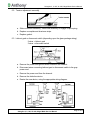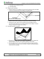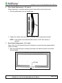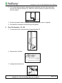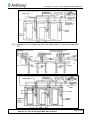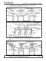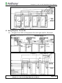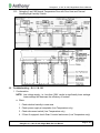
1
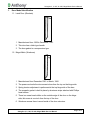
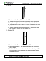
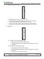
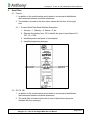
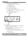
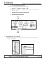
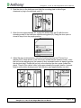
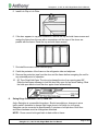
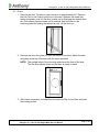
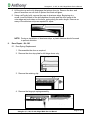
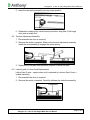
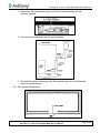
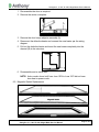
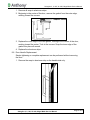
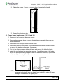
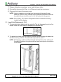
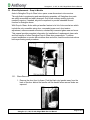
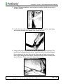
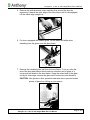
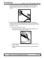
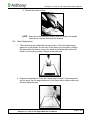
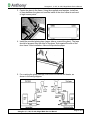
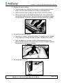
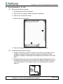
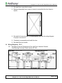
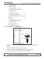
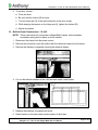
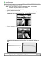
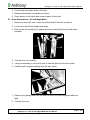
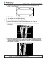
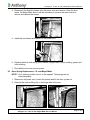
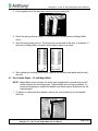
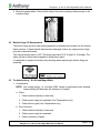
Swingline 3
Swingline 2
Swingline 180
XL 400
Magni-Matic
Service Manual
Swingline 3, 2, 180, XL-400, Magni-Matic Service Manual
TABLE OF CONTENTS
1.
Door Model Identification ................................................................................................... 5
1.1. Latch Door (Obsolete) ............................................................................................... 5
1.2. Magni-Matic (Woodcore) ........................................................................................... 5
1.3. XL 400 ....................................................................................................................... 6
1.4. Swingline 180 ............................................................................................................ 6
1.5. Swingline 2 with Drop-In Glass .................................................................................. 7
1.6. Swingline 3 ................................................................................................................ 7
1.6.1. Swingline 3 with Non-Adjustable Hinging........................................................ 7
1.6.2. Swingline 3 with Adjustable Hinging ............................................................... 7
2.
Serial Plate ........................................................................................................................ 8
2.1. Current ...................................................................................................................... 8
2.1.1. Current Serial Plate Serial Number Description .............................................. 8
2.2. SL-2 & 180................................................................................................................. 8
2.2.1. SL-2 and 180 Door Model Number Description .............................................. 9
2.2.2. SL-2 and 180 Serial Number Description........................................................ 9
2.3. XL and Magni-Matic................................................................................................... 9
2.3.1. XL and Magni-Matic Door Model Number Description .................................... 9
2.3.2. XL and Magni-Matic Serial Number Description ........................................... 10
3.
Door Installation – SL-3, 2 and 180 ................................................................................. 10
4.
Swing Hinge Conversion – SL-3, 2 and 180 .................................................................... 12
4.1. Doors ....................................................................................................................... 13
4.2. Frame ...................................................................................................................... 14
5.
Door Dis-Assembly – SL-3 and 2 .................................................................................... 15
5.1. Door spring replacement ......................................................................................... 17
5.2. Tension adjustment assembly ................................................................................. 18
5.3. Lektroni gard or disconnect switch (depending upon the glass package wiring). .... 18
5.4. Replace metal mouldings ........................................................................................ 19
5.5. Re-install the black vinyl gasket............................................................................... 19
6.
Door Handle Replacement – SL-3 and 2 ......................................................................... 20
7.
Door Heater Replacement – SL-3 and 2 ......................................................................... 20
8.
Door Dis-Assembly – SL-180 .......................................................................................... 21
TITLE:
Swingline 3, 2, 180, XL-400, Magni-Matic Service Manual
REV.
Page 2 of 54
Swingline 3, 2, 180, XL-400, Magni-Matic Service Manual
9.
Door Repair – SL-180 ...................................................................................................... 22
9.1. Door Spring Replacement ....................................................................................... 22
9.2. Tension Adjustment Assembly ................................................................................ 23
9.3. Lektroni gard or Lektra-Gard Replacement ............................................................. 23
9.4. Door Heater Replacement ....................................................................................... 24
9.5. Magnetic Gasket Replacement................................................................................ 25
9.6. Door Handle Replacement ...................................................................................... 26
10. Frame Heater Replacement – SL-3, 2 and 180 ............................................................... 27
11. Lamp Shield Replacement – SL-3 ................................................................................... 28
12. Glass Replacement – Drop-In Models ............................................................................. 29
12.1. Glass Removal ..................................................................................................... 29
12.2. Glass Replacement............................................................................................... 33
13. Glass Replacement – SL-180 .......................................................................................... 36
13.1. Removing the Glass Package ............................................................................... 36
13.2. Installing the New Glass Package ........................................................................ 36
14. Wiring Diagrams – SL-3 .................................................................................................. 37
14.1. Swingline 3 Normal Temperature Door with Door Heat and ‘Normal Humidity/High
Humidity’ Switch (before EC 05) ........................................................................... 37
14.2. Swingline 3 Low Temperature Door with Lights and B.J. Disconnect (before EC 05)
.............................................................................................................................. 38
14.3. Swingline 3 Normal Temperature Door with Door Heat and ‘Normal Humidity/High
Humidity’ Switch (EC 05 or later) .......................................................................... 39
14.4. Swingline 3 Low Temperature Door with Lights and B.J. Disconnect (EC 05 or
later)...................................................................................................................... 39
15. Wiring Diagrams – SL-2 & 180 ........................................................................................ 40
15.1. Swingline 2 and 180 Low Temperature Door with Lights and B.J. Disconnect ..... 40
15.2. Swingline 2 and 180 Normal Temperature Door with Door Heat and ‘Normal
Humidity/High Humidity’ Switch ............................................................................ 41
16. Troubleshooting – SL-3, 2 & 180 ..................................................................................... 41
17. Door Installation – XL and Magni-Matic ........................................................................... 44
18. Mullion Heater Replacement – XL-400 ............................................................................ 45
19. Perimeter Heater Replacement – XL-400 ........................................................................ 46
20. Glass Replacement – XL and Magni-Matic...................................................................... 47
21. Door Heater Replacement – XL and Magni-Matic ........................................................... 48
22. Door Spring Replacement – XL and Magni-Matic............................................................ 49
23. Door Handle Repair – XL and Magni-Matic ..................................................................... 50
TITLE:
Swingline 3, 2, 180, XL-400, Magni-Matic Service Manual
REV.
Page 3 of 54
Swingline 3, 2, 180, XL-400, Magni-Matic Service Manual
24. Bottom Hinge Pin Replacement....................................................................................... 51
25. Troubleshooting – XL-400 and Magni-Matic .................................................................... 51
TITLE:
Swingline 3, 2, 180, XL-400, Magni-Matic Service Manual
REV.
Page 4 of 54
Swingline 3, 2, 180, XL-400, Magni-Matic Service Manual
1.
Door Model Identification
1.1. Latch Door (Obsolete)
1. Manufactured from 1958 to December, 1961.
2. This door has a latch-type handle.
3. The door gasket is a compression type.
1.2. Magni-Matic (Woodcore)
1. Manufactured from December 1961 to March, 1966.
2. The power cord exits the door seven inches from the top on the hinge side.
3. Spring tension adjustment is performed at the top hinge side of the door.
4. The magnetic gasket is held in place by aluminum strips attached with Phillips
head screws.
5. There is a screw head visible on the outside edge of the door on the hinge
side; this screw is one inch from the top of the door.
6. Woodcore means there is wood inside of the door extrusion.
TITLE:
Swingline 3, 2, 180, XL-400, Magni-Matic Service Manual
REV.
Page 5 of 54
Swingline 3, 2, 180, XL-400, Magni-Matic Service Manual
1.3. XL 400
1. Manufactured from March, 1966 to December, 1970.
2. The power cord exits the door seven inches from the top on the hinge side.
3. Spring tension adjustment is performed at the top hinge side of the door.
4. The magnetic gasket is held in place by aluminum strips attached with Phillips
head screws.
5. There is a screw head visible on the outside edge of the door on the hinge
side; this screw is six inches from the top of the door.
1.4. Swingline 180
1. Manufactured from December, 1970 to January, 1976.
2. Magnetic gasket is about ¾” wide and goes around the back (refrigerated
side) of the door.
3. Can be identified by a recess in the center of the door on the hinge side. This
is the point of spring tension adjustment and the point from which the door
heater power cord exits.
TITLE:
Swingline 3, 2, 180, XL-400, Magni-Matic Service Manual
REV.
Page 6 of 54
Swingline 3, 2, 180, XL-400, Magni-Matic Service Manual
1.5. Swingline 2 with Drop-In Glass
1. Manufactured from January, 1976 to June, 1980.
2. Can be identified by the wide magnetic gasket, (about 1-3/8” wide) that
covers the entire back frame (refrigerated side) of the door.
3. A recess in the center of the door on the hinge side contains the spring
adjustment and is the point from which the door heater power cord exits..
1.6. Swingline 3
1.6.1. Swingline 3 with Non-Adjustable Hinging
1. Manufactured from July, 1980 to March, 1983.
2. A new door extrusion is the only difference between this door and the
Swingline 2.
1.6.2. Swingline 3 with Adjustable Hinging
1. Manufactured from March, 1983 to present.
2. The only difference between this door and the original SL-3 is the door
stop plate.
3. This model is not covered in this manual.
TITLE:
Swingline 3, 2, 180, XL-400, Magni-Matic Service Manual
REV.
Page 7 of 54
Swingline 3, 2, 180, XL-400, Magni-Matic Service Manual
2.
Serial Plate
2.1. Current
1. In addition to the model number and to assist in correct parts identification,
the frame serial number should be referenced.
2. The number is located on the door frame, above the first door on the right
end.
2.1.1. Current Serial Plate Serial Number Description
1. January = 1, February = 2, March = 3, etc.
2. Subtract this number from 100 to identify the year of manufacture. Ex.
100 - 18 = 1982.
3. Identifies product and place of manufacture.
4. Identifies engineering changes.
2.2. SL-2 & 180
1. In addition to the model number and to assist in correct parts identification,
the frame serial number should be referenced.
2. The serial plate is located on the side of one of the mullions (the posts
between the door openings).
TITLE:
Swingline 3, 2, 180, XL-400, Magni-Matic Service Manual
REV.
Page 8 of 54
Swingline 3, 2, 180, XL-400, Magni-Matic Service Manual
2.2.1. SL-2 and 180 Door Model Number Description
1. R – Identifies door as Swingline 180 or Swingline 2.
2. K – Identifies door size.
3. 4 – Identifies a 4-door frame.
4. SC3 – Identifies glass application.
2.2.2. SL-2 and 180 Serial Number Description
1. 10 – January = 1, February = 2, March = 3, etc.
2. 27 – Subtract this number from 100 to identify the year of manufacture.
Ex. 100 - 27 = 1973.
3. N – Identifies product and place of manufacture.
4. 07 – Identifies engineering changes.
Door Model
R
K
4
SC3
Serial Number
1) 10
2) 27
3) N
4) 07
2.3. XL and Magni-Matic
1. In addition to the model number and to assist in correct parts identification,
the frame serial number should be referenced.
2. The serial plate is located on the side of one of the mullions (the posts
between the door openings).
2.3.1. XL and Magni-Matic Door Model Number Description
1. XL doors are identified as shown, or with the letter prefix H; such as
HK.
2. K – Identifies door size.
3. 4 – Identifies a 4-door frame.
TITLE:
Swingline 3, 2, 180, XL-400, Magni-Matic Service Manual
REV.
Page 9 of 54
Swingline 3, 2, 180, XL-400, Magni-Matic Service Manual
4. SC3 – Identifies glass application.
2.3.2. XL and Magni-Matic Serial Number Description
5. January = 1, February = 2, March = 3, etc.
6. Subtract this number from 100 to identify the year of manufacture. Ex.
100 - 27 = 1973.
7. Identifies product and place of manufacture.
8. Identifies engineering changes.
Door Model
K
4
SC3
Serial Number
1) 7
2) 32
3) N
4) 02
3.
Door Installation – SL-3, 2 and 180
1. Lift the door into the frame to engage the top door hinge pin (A) into the top door
hinge pin bushing (B).
TITLE:
Swingline 3, 2, 180, XL-400, Magni-Matic Service Manual
REV.
Page 10 of 54
Swingline 3, 2, 180, XL-400, Magni-Matic Service Manual
2. Rest the door on the hold-open and slide the mounting plate to allow finger
clearance to plug in the electrical cord (C).
3. Open the door approximately 45° to align the bottom door pin (D) with the door
mounting socket in the hold-open slide mounting plate (E). Swing the door open or
closed to drop it into the proper position.
4. Adjust the door closing tension, using the furnished hex key tool. The tool is a
standard 5/16” allen wrench. If the tool is lost, another can be obtained locally. Insert
the tool into the adjusting nut (the center-of-door recessed location is always opposite
the electrical plug). Rotate the tool only in the direction the door opens (toward the
glass). Three to four ratchet ‘clicks’ gives approximately the proper tension. Increase
tension until positive closing occurs, with the door open approximately one inch.
TITLE:
Swingline 3, 2, 180, XL-400, Magni-Matic Service Manual
REV.
Page 11 of 54
Swingline 3, 2, 180, XL-400, Magni-Matic Service Manual
5. Install Lok-Clip or Lok-Plate.
6. If the door appears to sag after installation, remove the top and side frame screws and
wedge the frame from the rear with a screwdriver until the tops of the doors are
parallel with the frame. Reset the top and side frame screws.
7. Re-install the screw in each electrical plug.
8. Caulk the perimeter of the frame on the refrigerator side and adjoiners.
9. Remove the protective tape from the door and the frame before energizing the unit for
any extended period of operation.
10. 90° Door Stop/Hold-Open. The door stop keeps the door from opening past 90°.
Slide the hold-open sideways to hold the door fully open for fast stock loading. Slide
the hold-open back out and the door again closes automatically.
4.
Swing Hinge Conversion – SL-3, 2 and 180
Ardco Swingline is a reversible hinge door. Should remodeling or changes in store
traffic make it desirable to change right hinge doors to left hinge (or vice versa),
Swingline can be converted in approximately 5 minutes or less per door. Both door
and frame hardware must be changed as described.
NOTE: Doors cannot be hinged back-to-back within a frame.
TITLE:
Swingline 3, 2, 180, XL-400, Magni-Matic Service Manual
REV.
Page 12 of 54
Swingline 3, 2, 180, XL-400, Magni-Matic Service Manual
4.1. Doors
1. Remove the door. To remove, open the door to approximately 45°. Remove
the Lok-Clip or Lok-Plate from the top of the door. Remove the screw that
retains the power cord. Lift the door up and out to disengage the bottom door
pin. Door closing tensions need not be relieved. Rest the door on the
mounting plate and unplug the lelectrical cord. Lift the door out.
2. Remove the door stop plate (A) from the bottom of the door. Attach the door
stop plate to the top of the door with the screw provided.
NOTE: The straight edge of the door stop plate faces the front of the door.
Turn the door upside down and the door is ready to install.
3. After frame conversion, re-install the door and Lok-Clip or Lok-Plate and reset
the closing tension.
TITLE:
Swingline 3, 2, 180, XL-400, Magni-Matic Service Manual
REV.
Page 13 of 54
Swingline 3, 2, 180, XL-400, Magni-Matic Service Manual
4.2. Frame
1. Remove the hold-open slide (A) and hold-open slide mounting plate (B) and
door mounting socket (C).
Left Hinge
Right Hinge
2. Exchange the top door hinge bushing (D) with the plastic plug (E).
TITLE:
Swingline 3, 2, 180, XL-400, Magni-Matic Service Manual
REV.
Page 14 of 54
Swingline 3, 2, 180, XL-400, Magni-Matic Service Manual
3. For end doors, transfer the electrical output cap (F). For a mullion hinged
door, remove screws, rotate the stainless electrical cover plate (H) to maintain
polarity and replace screws (G).
4. Re-install doors and reset closing tension.
5.
Door Dis-Assembly – SL-3 and 2
1. To remove the door, remove the screw and unplug the electrical cord.
2. Open the door to approximately 45°
TITLE:
Swingline 3, 2, 180, XL-400, Magni-Matic Service Manual
REV.
Page 15 of 54
Swingline 3, 2, 180, XL-400, Magni-Matic Service Manual
3. Remove the Lok-Clip or Lok-Plate from the top of the door.
4. Lift the door up and out to disengage the bottom door pin. Remove the door and
place it face down on soft cloth to protect the finish and glass.
5. Remove the gasket by peeling it away from the back of the door.
6. Using a stiff putty knife, remove the narrow aluminum outer moulding. This is best
done by beginning at a corner. Insert the knife between the moulding and the door
frame at the outer edge and push down on the knife, prying along the entire length.
Remove the outer moulding as required for repair (hinge side).
7. Remove the wide aluminum inner moulding from the hinge side by squeezing it
toward the outer edge of the door frame until it is disengaged. Lift the inside edge
straight up.
TITLE:
Swingline 3, 2, 180, XL-400, Magni-Matic Service Manual
REV.
Page 16 of 54
Swingline 3, 2, 180, XL-400, Magni-Matic Service Manual
8. Remove the center coverplate.
9. At this point, the door tension adjustment assembly (springs, etc.) or disconnect
switch can be repaired or changed without further teardown.
5.1. Door spring replacement
a. Remove retaining clip (A).
b. Remove hinge pin spring assembly (B).
c. Insert new spring assembly into proper position (C).
d. Replace retaining clip.
e. Replace aluminum strips.
f. Replace gasket.
TITLE:
Swingline 3, 2, 180, XL-400, Magni-Matic Service Manual
REV.
Page 17 of 54
Swingline 3, 2, 180, XL-400, Magni-Matic Service Manual
5.2. Tension adjustment assembly
a. Slide out tension assembly. Install new assembly to engage torque spring.
b. Replace coverplate and aluminum strips.
c. Replace gasket.
5.3. Lektroni gard or disconnect switch (depending upon the glass package wiring).
2 wires = lektroni gard
3 wires = disconnect switch
a. Remove the power cord ground screw located in the channel.
b. Disconnect wires connecting lektroni gard or disconnect switch to the gray
power cord.
c. Remove the power cord from the channel.
d. Remove the defective device.
e. Rewire the new device, using the appropriate wiring diagram.
TITLE:
Swingline 3, 2, 180, XL-400, Magni-Matic Service Manual
REV.
Page 18 of 54
Swingline 3, 2, 180, XL-400, Magni-Matic Service Manual
f. Re-install snap-out aluminum strips.
g. Re-install gasket.
5.4. Replace metal mouldings
a. Place the wide inner moulding into the groovein the channel at the outer edge
of the door frame and reset the moulding on the glazing tape.
b. Place the narrow outer moulding into the groove of the inner moulding.
c. Starting at a corner, tap the outer moulding until the mouldings snap into
place. Be certain that the inner moulding engages into the channel. Continue
doing so along the full length of the molding.
5.5. Re-install the black vinyl gasket
a. Beginning at a corner, pull the inner edge of the gasket into the channel that
faces the glass of the wide outer moulding. Repeat at each corner.
b. Work the gasket into the outer moulding channel while pressing the gasket
into the channel of the narrow inner moulding. Complete installing the gasket
at the center door opening.
TITLE:
Swingline 3, 2, 180, XL-400, Magni-Matic Service Manual
REV.
Page 19 of 54
Swingline 3, 2, 180, XL-400, Magni-Matic Service Manual
6.
Door Handle Replacement – SL-3 and 2
Simple tightening or complete replacing can be done without removing the door.
1. Peel the gasket away from the handle area.
2. Tighten the screws if they are loose or unscrew them if replacing the handle.
NOTE: If the handle is mounted with allen screws, a 5/32” allen wrench is
required.
7.
Door Heater Replacement – SL-3 and 2
Steps 1 thru 6 on Dis-Assembly should be followed to remove the entire gasket and all
snap-in moulding.
1. After removing the snap-in moulding, disconnect the defective heater and connect
the new heater.
TITLE:
Swingline 3, 2, 180, XL-400, Magni-Matic Service Manual
REV.
Page 20 of 54
Swingline 3, 2, 180, XL-400, Magni-Matic Service Manual
2. Pull out the defective heater (removing plastic retainers) and insert the new heater
wire into the channel extrusion (A). Make sure that the heater is pushed all the way
into the channel.
3. Position the plastic heater retainers in the same area they were in originally.
4. Re-install the coverplate, aluminum strips and gasket.
8.
Door Dis-Assembly – SL-180
1. To remove the door, open the door to approximately 45°.
2. Remove the Lok-Plate.
3. Unplug the electrical cord.
TITLE:
Swingline 3, 2, 180, XL-400, Magni-Matic Service Manual
REV.
Page 21 of 54
Swingline 3, 2, 180, XL-400, Magni-Matic Service Manual
4. Lift the door up and out to disengage the bottom door pin. Remove the door and
place it face down on soft cloth to protect the finish and glass.
5. Using a stiff putty knife, remove the snap-in aluminum strips. Beginning at a
corner, insert the blade of the knife between the strip and the door frame at the
outer edge and push down on the knife, prying along the entire length. Remove as
many of the aluminum strips as required for repair.
NOTE: During re-installation of aluminum strips, a plastic hammer should be used
to prevent distortion.
9.
Door Repair – SL-180
9.1. Door Spring Replacement
1. Dis-assemble the door as required.
2. Remove the door stop plate for left hinge doors only.
3. Remove the retaining clip.
4. Remove the hinge pin spring assembly.
TITLE:
Swingline 3, 2, 180, XL-400, Magni-Matic Service Manual
REV.
Page 22 of 54
Swingline 3, 2, 180, XL-400, Magni-Matic Service Manual
5. Insert the new spring assembly into the proper position.
6. Replace the retaining clip, aluminum strip and door stop plate (if left hinge
door) and re-install door.
9.2. Tension Adjustment Assembly
1. Dis-assemble the door as required.
2. Remove the center coverplate. Slide out the tension adjustment assembly.
Install the new assembly to engage the torque spring.
3. Replace the coverplate and aluminum strip and re-install the door.
9.3. Lektroni gard or Lektra-Gard Replacement
Lektra-Gard (2 wire – open contact unit) is replaced by Lektroni-Gard (4 wire –
sealed assembly).
1. Dis-assemble the door as required.
2. Remove the center coverplate. Carefully withdraw the defective assembly.
TITLE:
Swingline 3, 2, 180, XL-400, Magni-Matic Service Manual
REV.
Page 23 of 54
Swingline 3, 2, 180, XL-400, Magni-Matic Service Manual
3. Disconnect the old and insert the new Lektroni-Gard assembly into the
extrusion channel.
4. Connect the new assembly per the wiring diagram.
5. Re-install the snap-in aluminum strip. Re-install the door and Lok-Plate and
reset the closing tension.
9.4. Door Heater Replacement
TITLE:
Swingline 3, 2, 180, XL-400, Magni-Matic Service Manual
REV.
Page 24 of 54
Swingline 3, 2, 180, XL-400, Magni-Matic Service Manual
1. Dis-assemble the door as required.
2. Remove the center coverplate.
3. Remove the door torque adjuster assembly (A).
4. Disconnect the defective heater and connect the new heater per the wiring
diagram.
5. Pull out the defective heater and insert the new heater completely into the
channel (B) in the extrusion.
6. Re-assemble and re-install door.
NOTE: Ardco cooler doors, built from June 1974 to June 1975 did not have
door heat or power cords.
9.5. Magnetic Gasket Replacement
TITLE:
Swingline 3, 2, 180, XL-400, Magni-Matic Service Manual
REV.
Page 25 of 54
Swingline 3, 2, 180, XL-400, Magni-Matic Service Manual
1. Remove all snap-in aluminum strips.
2. Beginning in the center of the door, remove the gasket from the outer edge,
working toward the corners.
3. Replace the outer edge of the new gasket, starting at the corners of the door,
working toward the center. Tuck in the corners. Snap the inner edge of the
gasket into place all around.
4. Replace the aluminum strips.
9.6. Door Handle Replacement
Simple tightening or complete replacement can be performed without removing
the door.
1. Remove the snap-in aluminum strip on the handle side only.
TITLE:
Swingline 3, 2, 180, XL-400, Magni-Matic Service Manual
REV.
Page 26 of 54
Swingline 3, 2, 180, XL-400, Magni-Matic Service Manual
2. Tighten the screws, if loose, or unscrew them if replacing the handle.
3. Replace the aluminum strip.
10. Frame Heater Replacement – SL-3, 2 and 180
1. Disconnect the frame from the power source.
2. Remove the necessary doors to expose the stainless coverplates that cover the
defective heaters.
3. Remove all door hold-open slides from the frame.
4. Remove all stainless coverplates to expose the defective heater. Use a flat blade
to remove the stainless coverplates, if necessary.
5. Cut out the defective heater at the cold leads and remove the defective heater.
6. Install the new heater in the appropriate grooves. Check the routing of the heater
as per the appropriate wiring diagram. Check the heater for continuity. Splice new
heater to cold leads using line-to-line connectors.
NOTE: Use extreme care to prevent the heater from touching itself. It may be
necessary to physically keep the heater from touching by using foil tape or
permagum in the area of the egress point.
TITLE:
Swingline 3, 2, 180, XL-400, Magni-Matic Service Manual
REV.
Page 27 of 54
Swingline 3, 2, 180, XL-400, Magni-Matic Service Manual
7. Replace all stainless coverplates, screws and hold-open slides.
8. Re-install all doors and Lok-Clips or Lok-Plates and reset the door tension.
9. Reconnect the frame to the power source.
NOTE: Using a screwdriver or similar sharp instrument will damage the new
heater. A roller tool such as those used to assemble aluminum screens in
household doors should be used to ‘roll’ the heater into the grooves.
NOTE: Prior to May, 1974, Normal Temperature frames contained no factoryinstalled mullion heaters.
11. Lamp Shield Replacement – SL-3
1. To remove the lamp shield, push the metal clip. This will disengage the side of the
shield. Rotate the entire shield to disengage the opposite side.
2. To replace the shield, place the shield around the lamp and engage the shield into
the channel along one side. The shield will snap back into place.
NOTE: All shields on mullions and the left ends of frames have clips at the top of
the shield. Shields on the right end of the frame have clips on the bottoms
of the shields.
TITLE:
Swingline 3, 2, 180, XL-400, Magni-Matic Service Manual
REV.
Page 28 of 54
Swingline 3, 2, 180, XL-400, Magni-Matic Service Manual
12. Glass Replacement – Drop-In Models
Ardco’s Swingline ‘Drop-In Glass’ door opens a new dimension in door service.
Through Ardco’s engineering and manufacturing expertise, all Swingline door parts
are easily accessible and easily changed. Only a few ordinary working tools are
needed to service, if needed, any door component to provide extended life and
function for Swingline doors.
With Drop-In Glass, Ardco adds yet another feature to its list of door exclusives which
include the only reversible swing door, concealed power cord, door tension
adjustment, narrow-crowned extrusions, substantially increased glass area and more.
This manual provides complete information for installation of replacement glass units
and field service of other Swingline Drop-In Glass door components. To assure
correct installation or service with minimum time and effort, read the entire instructions
before performing each procedure.
12.1. Glass Removal
1. Remove the door from its frame. Peel the black vinyl gasket away from the
back of the door behind the handle until the handle screw access holes are
exposed.
TITLE:
Swingline 3, 2, 180, XL-400, Magni-Matic Service Manual
REV.
Page 29 of 54
Swingline 3, 2, 180, XL-400, Magni-Matic Service Manual
2. Using a Phillips screwdriver, remove the door handle. Handle screws stay in
the door channel.
3. Lay the door on a flat surface, backside up. Starting at a corner, peel away
and remove the black vinyl gasket from around the door.
4. Using a stiff putty knife, remove the narrow aluminum outer moulding. This
is best done by beginning at a corner. Insert the blade of the knife between
the moulding and the door frame at the outer edge and push down on the
knife, prying along the entire length. Remove the entire outer moulding from
around the door. Take care not to deform the moulding.
TITLE:
Swingline 3, 2, 180, XL-400, Magni-Matic Service Manual
REV.
Page 30 of 54
Swingline 3, 2, 180, XL-400, Magni-Matic Service Manual
5. Remove the wide aluminum inner moulding from around the door by
squeezing it toward the outer edge of the door frame until it is disengaged.
Lift the inside edge straight up.
6. For doors equipped with heated glass, cut the balck and white wires
extending from the glass near the glass frame.
7. Remove the insulated glass unit from the door frame. To do so, raise the
end of the door and place a block under an unbroken end of glass or a
corner and pull down on the door frame. Grasp the raised end of the glass
unit by its outer edge, remove the glass unit from the door and discard it.
CAUTION: Use gloves or other protection and take care to prevent broken
pieces of glass from falling on your person.
TITLE:
Swingline 3, 2, 180, XL-400, Magni-Matic Service Manual
REV.
Page 31 of 54
Swingline 3, 2, 180, XL-400, Magni-Matic Service Manual
8. When the glass has been removed, scrape away any wax-like wedges
remaining on the inside of the door frame at each corner. Also, clean away
any dirt or particles remaining on the front gasket or other mounting
surfaces.
9. A new disconnect switch is provided with a replacement heated glass
package. The wiring on the glass package may vary from the original glass
package; therefore, the new disconnect switch must be used, even if the old
device has not failed.
a. To remove the original Lektroni-Gard:
1. Remove the door center coverplate by unscrewing and prying it out
of the channel, pulling the power cord with it.
2. Pull the white frame heater out of the channel to a point past the door
center coverplate.
3. Slide the Lektroni-Gard down the channel and out of the cover plate
opening.
TITLE:
Swingline 3, 2, 180, XL-400, Magni-Matic Service Manual
REV.
Page 32 of 54
Swingline 3, 2, 180, XL-400, Magni-Matic Service Manual
4. Discard the Lektroni-Gard.
NOTE: Removal of the disconnect switch does not require coverplate
removal, as it can be lifted from the channel.
12.2. Glass Replacement
1. .Place blocks at each end within the door frame. Place the replacement
glass unit on the blocks. At one end, lift the frame up to the glass. Holding
the glass within the frame, remove the block and rest the glass within the
frame on the working surface. Repeat at the other end.
2. Diagonal measurement of the door frame must be equal. If measurements
are not equal, tap the appropriate end of the frame with a rubber mallet and
recheck measurements.
TITLE:
Swingline 3, 2, 180, XL-400, Magni-Matic Service Manual
REV.
Page 33 of 54
Swingline 3, 2, 180, XL-400, Magni-Matic Service Manual
3. Center the glass in the frame. Using the supplied wood wedges, install two
of them between the glass unit and the inside of the door frame at each end
of eight corner points.
4. Install the provided glazing tape (paper side up, around the glass). The tape
should be pressed onto the edge of the glass, flush against the side of the
door frame. After installation, remove the protective paper.
5. For re-wiring the glass package, disconnect the switch and heater, as
shown in the wiring diagram.
TITLE:
Swingline 3, 2, 180, XL-400, Magni-Matic Service Manual
REV.
Page 34 of 54
Swingline 3, 2, 180, XL-400, Magni-Matic Service Manual
6. Replace the metal moldings.
a. Place the wide inner molding into the groove in the channel at the outer
edge of the door frame and rest the molding on the glazing tape.
b. Place the narrow outer molding into the groove of the inner molding.
c. Starting at a corner, push inward and down on the outer molding until
the moldings snap into place. Be certain that the inner molding enagaes
into the channel. Continue pushing along the full length of the molding.
7. Re-install the black vinyl gasket.
a. Beginning at a corner, pull the inner edge of the gasket into the channel
of the wide inner molding that faces the glass. Repeat at each corner.
b. Work the gasket into the outer molding channel while prtessing the
gasket into the channel of the narrow outer molding. Complete installing
the gasket at the center door opening.
8. Re-install the door handle.
TITLE:
Swingline 3, 2, 180, XL-400, Magni-Matic Service Manual
REV.
Page 35 of 54
Swingline 3, 2, 180, XL-400, Magni-Matic Service Manual
13. Glass Replacement – SL-180
13.1. Removing the Glass Package
1. Dis-assemble the door as required.
2. Remove the door gasket, heater and tension assembly.
3. Remove the corner block screw.
4. Remove the door members.
5. Remove the glass package with the vinyl molding and discard.
13.2. Installing the New Glass Package
1. Starting at the bottom center of the glass, fit the new vinyl molding around
the glass, notching it at each corner for a proper fit (using the old vinyl
molding as a pattern). Heated glass units require that a hole be cut for glass
leads.
2. Re-assemble the door frame, ensuring that the glass package and the vinyl
molding are fully inserted in the door extrusion channel. If a tight fit occurs, it
may be necessary to use furniture clamps or a similar device to insert the
new unit.
TITLE:
Swingline 3, 2, 180, XL-400, Magni-Matic Service Manual
REV.
Page 36 of 54
Swingline 3, 2, 180, XL-400, Magni-Matic Service Manual
3. Re-install the corner block screws.
4. Measure diagonally from corner to corner to ensure that the door frame is
square.
5. Re-install all removed parts. For heated glass units, see the wiring diagram
for proper connections.
6. Completely re-assemble and install the door.
9. Re-install the door handle.
14. Wiring Diagrams – SL-3
14.1. Swingline 3 Normal Temperature Door with Door Heat and ‘Normal
Humidity/High Humidity’ Switch (before EC 05)
TITLE:
Swingline 3, 2, 180, XL-400, Magni-Matic Service Manual
REV.
Page 37 of 54
Swingline 3, 2, 180, XL-400, Magni-Matic Service Manual
14.2. Swingline 3 Low Temperature Door with Lights and B.J. Disconnect (before EC
05)
TITLE:
Swingline 3, 2, 180, XL-400, Magni-Matic Service Manual
REV.
Page 38 of 54
Swingline 3, 2, 180, XL-400, Magni-Matic Service Manual
14.3. Swingline 3 Normal Temperature Door with Door Heat and ‘Normal
Humidity/High Humidity’ Switch (EC 05 or later)
14.4. Swingline 3 Low Temperature Door with Lights and B.J. Disconnect (EC 05 or
later)
TITLE:
Swingline 3, 2, 180, XL-400, Magni-Matic Service Manual
REV.
Page 39 of 54
Swingline 3, 2, 180, XL-400, Magni-Matic Service Manual
15. Wiring Diagrams – SL-2 & 180
15.1. Swingline 2 and 180 Low Temperature Door with Lights and B.J. Disconnect
TITLE:
Swingline 3, 2, 180, XL-400, Magni-Matic Service Manual
REV.
Page 40 of 54
Swingline 3, 2, 180, XL-400, Magni-Matic Service Manual
15.2. Swingline 2 and 180 Normal Temperature Door with Door Heat and ‘Normal
Humidity/High Humidity’ Switch
16. Troubleshooting – SL-3, 2 & 180
1. Condensation
NOTE: Low voltage supply; i.e., less than 108V, results in significantly lower wattage.
Lower wattage will decrease the efficiency of heaters.
a. Glass
1. Check relative humidity in case area
2. Check power supply at receptacle (Low Temperature only)
3. Check disconnect switch (Low Temperature only)
4. If Scan-X equipped, check Scan-X control and sensor (Low Temperature only)
TITLE:
Swingline 3, 2, 180, XL-400, Magni-Matic Service Manual
REV.
Page 41 of 54
Swingline 3, 2, 180, XL-400, Magni-Matic Service Manual
b. Door Extrusion
1. Check relative humidity in case area
2. Check power supply at receptacle
3. Check continuity of heater
4. If Scan-X equipped, check Scan-X control and sensor
c. Frame
1. Check relative humidity in case area
2. Check power supply to frame heaters
3. Check continuity of frame heaters
4. If Scan-X equipped, check Scan-X control and sensor
5. Check to ensure back of frame perimeter is caulked properly
2. Mechanical
a. Door Will Not Close
1. Door requires tension adjustment
2. Damaged torque rod
3. Ratchet assembly inoperative
4. Torque rod not engaged
5. Door stop pin screw loose, binding
6. Door stop pin stripped or missing (Mounting hardware should be replaced with
welded plate which has stop pin and hinge socket welded to the mounting
plate)
7. Hold-open slide screw loose, binding
8. Lok-Plate or Lok-Clip is binding
9. Foreign object restricting closing
b. Door Not Sealing
1. Magnetic gasket damaged
2. Door not closing completely (see ‘Door Will Not Close’)
c. Door Saw-toothed
1. Door out of square (Diagonal dimensions should be within 1/16”)
2. Frame out of square (Diagonal dimensions should be within 1/8”)
3. Glass package shifted
4. Worn hinge pin and bushing
TITLE:
Swingline 3, 2, 180, XL-400, Magni-Matic Service Manual
REV.
Page 42 of 54
Swingline 3, 2, 180, XL-400, Magni-Matic Service Manual
5. Worn mounting hardware
6. Case not level on floor
3. Ballasts
a. Lamps Won’t Start
1. Lamp failure
2. Poor lamp-to-lampholder contact
3. Incorrect wiring
4. Low voltage supply
5. Dirty lamps or lamp pins
6. Low or high lamp bulb-wall temperature
7. High humidity
8. Fixture not grounded
9. Improper ballast application
10. Ballast failure
b. Short Lamp Life
1. Improper voltage
2. Improper wiring
3. Poor lamp-to-lampholder contact
4. Extremely short duty cycles (Greater than average number of lamp starts per
day. Check with lamp manufacturer)
5. Defective lamps
6. Improper ballast application
7. Defective ballast
c. Lamp Flicker (Spiraling or Swirling Effect)
1. New lamps (should be operated 100 hours for proper seasoning)
2. Defective lamps
3. Improper voltage
4. Improper ballast application
5. Defective ballast
d. Audible Ballast ‘Hum’
1. Loose fixture louvers, panels or other parts
2. Insecure ballast mounting
TITLE:
Swingline 3, 2, 180, XL-400, Magni-Matic Service Manual
REV.
Page 43 of 54
Swingline 3, 2, 180, XL-400, Magni-Matic Service Manual
3. Defective ballast
e. Very Slow Starting
1. Improper voltage – too low
2. Poor lamp-to-lampholder contact
3. Defective lamp
4. Improper circuit wiring
5. Inproper ballast application
6. Bulb-wall temperature too low or too high
f. Blinking
1. High voltage
2. Improper wiring or installation
3. Defective ballast
4. Wrong type lamps
5. Wrong number of lamps
17. Door Installation – XL and Magni-Matic
1. Be sure that the locknut (B) is on the upper hinge pin (A), but not tight against the
frame.
2. Insert the top of the door over the top hinge pin (A).
3. Lift the door up and set the door bottom onto the bottom hinge pin (C).
4. Plug in the power cord and secure it with a screw, if available.
TITLE:
Swingline 3, 2, 180, XL-400, Magni-Matic Service Manual
REV.
Page 44 of 54
Swingline 3, 2, 180, XL-400, Magni-Matic Service Manual
5. To set door tension:
a. Close the door.
b. Be sure that the locknut (B) is loose.
c. Turn the hinge pin (A) in the same direction as the door closes.
d. While keeping the tension on the hinge pin (A), tighten the locknut (B).
e. Adjust as needed.
18. Mullion Heater Replacement – XL-400
NOTE: These instructions do not pertain to Magni-Matic frames, as the stainless
coverplates were glued in place on those models.
1. Disconnect the frame from the power source.
2. Remove the doors that cover the mullion with the defective heater from the frame.
3. Remove the stainless coverplate covering the defective heater.
4. Cut out the defective heater at the cold lead and install a new heater.
Freezer (LT) Frame & Mullion Heaters
5. Replace the stainless coverplate and doors.
6. Reset tension on the doors and connect power to the frame.
TITLE:
Swingline 3, 2, 180, XL-400, Magni-Matic Service Manual
REV.
Page 45 of 54
Swingline 3, 2, 180, XL-400, Magni-Matic Service Manual
19. Perimeter Heater Replacement – XL-400
NOTE: These instructions do not pertain to Magni-Matic frames, as the stainless
coverplates were glued in place on those models.
1. Disconnect the frame from the power source.
2. Remove the doors from the frame.
3. Remove the stainless coverplates to expose the defective perimeter heater (the
original heater was encased in aluminum foil – the replacement will not be).
4. Remove the defective heater.
5. Install the new heater in the channel (the original heater for low temperature
applications made a double loop around the frame – the replacement will make only
one).
Cooler (NT) Frame Heaters
Freezer (LT) Frame Heaters
TITLE:
Swingline 3, 2, 180, XL-400, Magni-Matic Service Manual
REV.
Page 46 of 54
Swingline 3, 2, 180, XL-400, Magni-Matic Service Manual
6. Connect the new heater at the cold leads.
7. Replace the stainless coverplates and doors.
8. Reset tension on the doors and connect power to the frame.
20. Glass Replacement – XL and Magni-Matic
1. Disconnect the power cord, loosen the locknut and lift the door up and out.
2. Lay the door flat with the handle side down.
3. Remove the outer molding (A), gasket and inner molding (B) from the entire door
perimeter.
4. Turn the door over carefully.
5. It may be necessary to use a putty knife to free the glass from the door frame.
6. Carefully push the glass package from the door frame.
7. Clean any old glazing tape from the inner lip of the front door flange and add new
tape.
8. Turn the door over.
TITLE:
Swingline 3, 2, 180, XL-400, Magni-Matic Service Manual
REV.
Page 47 of 54
Swingline 3, 2, 180, XL-400, Magni-Matic Service Manual
9. Center the new glass package into the frame and insert wooden wedges at the
corners to secure the glass.
10. Re-install the inner molding (B), gasket and outer molding (A).
11. Re-install the door and connect the power.
21. Door Heater Replacement – XL and Magni-Matic
1. Disconnect the power cord, loosen the locknut and lift the door up and out.
2. Remove all the outer moldings (A), remove the gasket and remove all the inner
moldings (B).
3. Remove the spring retainer screw (C – XL door) and slide the spring and block down
and out. On Magni-Matic doors, the screw holding the block will need to be removed.
There may also be a screw on the inner side of the block. The glass package must be
removed to get to this screw.
TITLE:
Swingline 3, 2, 180, XL-400, Magni-Matic Service Manual
REV.
Page 48 of 54
Swingline 3, 2, 180, XL-400, Magni-Matic Service Manual
4. Disconnect the defective heater from the power cord and remove it from the door
frame. On Magni-Matic doors it will be necessary to remove the wood inserts to
remove and replace the heater.
5. Install the new heater and attach it to the power cord.
6. Replace the block and spring (wood inserts if Magni-Matic), inner molding, gasket and
outer molding.
7. Re-install the door and connect power.
22. Door Spring Replacement – XL and Magni-Matic
NOTE: First, determine which door is to be repaired. The springs are not
interchangeable.
1. Disconnect the power cord, loosen the locknut and lift the door up and out.
2. Remove the outer molding (A) on the hinge side of the door.
TITLE:
Swingline 3, 2, 180, XL-400, Magni-Matic Service Manual
REV.
Page 49 of 54
Swingline 3, 2, 180, XL-400, Magni-Matic Service Manual
3. Lift the gasket out of the way and remove the inner molding (B).
4. Reove the spring retainer screw (C). This screw will not be present on Magni-Matic
doors.
5. Slide the spring down and out. The block may be removed at this time, if necessary. If
the door is a Magni-Matic, the block will be held in place by a screw.
6. After replacing the spring and/or block, replace the moldings and gasket and re-hang
the door.
23. Door Handle Repair – XL and Magni-Matic
NOTE: Magni-Matic doors and early XL doors were supplied with a handle that had a 9”
center between the mounting posts. These handles are no longer available. If it
becomes necessary to replace this handle, new holes may be drilled and the old
holes plugged.
1. To tighten or replace the door handle, remove the outer molding (A) on the handle
side only.
TITLE:
Swingline 3, 2, 180, XL-400, Magni-Matic Service Manual
REV.
Page 50 of 54
Swingline 3, 2, 180, XL-400, Magni-Matic Service Manual
2. Move the gasket aside. There will be holes in the inner molding to allow access to the
handle screws.
24. Bottom Hinge Pin Replacement
The bottom hinge pin and roller bearing assembly is threaded and screws into the bottom
frame member. If these threads have become damaged, Ardco can supply bottom hinge
pins with oversized threads.
The original threads were 1/2-20. The larger parts have 9/16-18 and 3/4-16 threads. The
frame can be re-drilled and re-tapped to accept these parts.
It is advisable to replace the bottom door bushing when replacing the bottom hinge pin
assembly.
25. Troubleshooting – XL-400 and Magni-Matic
1. Condensation
NOTE: Low voltage supply; i.e., less than 108V, results in significantly lower wattage.
Lower wattage will decrease the efficiency of heaters.
a. Glass
1. Check relative humidity in case area
2. Check power supply at receptacle (Low Temperature only)
3. Check lektroni-gard (Low Temperature only)
b. Door Extrusion
1. Check relative humidity in case area
2. Check power supply at receptacle
3. Check continuity of heater
TITLE:
Swingline 3, 2, 180, XL-400, Magni-Matic Service Manual
REV.
Page 51 of 54
Swingline 3, 2, 180, XL-400, Magni-Matic Service Manual
c. Frame
1. Check relative humidity in case area
2. Check power supply to frame heaters
3. Check continuity of frame heaters
4. Check to ensure back of frame perimeter is caulked properly
2. Mechanical
a. Door Will Not Close
1. Door requires tension adjustment
2. Damaged spring
3. Damaged hinge block assembly
4. Door stop pin loose, binding
5. Hinge pin w/roller bearing loose, binding or stripped (Oversized hinge pin
w/roller bearing available for replacement)
6. Hold-open slide loose or binding
7. Foreign object restricting closing
b. Door Not Sealing
1. Magnetic gasket damaged
2. Door not closing completely (see ‘Door Will Not Close’)
c. Door Saw-toothed
1. Door out of square (Diagonal dimensions should be within 1/16”)
2. Frame out of square (Diagonal dimensions should be within 1/8”)
3. Glass package shifted
4. Worn hinge block assembly
5. Worn bottom hinge pin w/roller bearing
6. Case not level on floor
3. Ballasts
a. Lamps Won’t Start
1. Lamp failure
2. Poor lamp-to-lampholder contact
3. Incorrect wiring
4. Low voltage supply
5. Dirty lamps or lamp pins
TITLE:
Swingline 3, 2, 180, XL-400, Magni-Matic Service Manual
REV.
Page 52 of 54
Swingline 3, 2, 180, XL-400, Magni-Matic Service Manual
6. Low or high lamp bulb-wall temperature
7. High humidity
8. Fixture not grounded
9. Improper ballast application
10. Ballast failure
b. Short Lamp Life
1. Improper voltage
2. Improper wiring
3. Poor lamp-to-lampholder contact
4. Extremely short duty cycles (Greater than average number of lamp starts per
day. Check with lamp manufacturer)
5. Defective lamps
6. Improper ballast application
7. Defective ballast
c. Lamp Flicker (Spiraling or Swirling Effect)
1. New lamps (should be operated 100 hours for proper seasoning)
2. Defective lamps
3. Improper voltage
4. Improper ballast application
5. Defective ballast
d. Audible Ballast ‘Hum’
1. Loose fixture louvers, panels or other parts
2. Insecure ballast mounting
3. Defective ballast
e. Very Slow Starting
1. Improper voltage – too low
2. Poor lamp-to-lampholder contact
3. Defective lamp
4. Improper circuit wiring
5. Inproper ballast application
6. Bulb-wall temperature too low or too high
TITLE:
Swingline 3, 2, 180, XL-400, Magni-Matic Service Manual
REV.
Page 53 of 54
Swingline 3, 2, 180, XL-400, Magni-Matic Service Manual
f. Blinking
1. High voltage
2. Improper wiring or installation
3. Defective ballast
4. Wrong type lamps
5. Wrong number of lamps
TITLE:
Swingline 3, 2, 180, XL-400, Magni-Matic Service Manual
REV.
Page 54 of 54