1
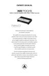
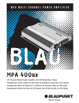
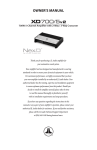
M7000
TABLE OF CONTENTS
INTRODUCTION
1
FEATURES
2-4
INSTALLATION BASICS
4 -8
INSTALLATION WIRING
9 -12
VARIOUS IMPEDANCE WIRING
13 -14
SPECIFICATION
15
Thank you for purchasing a Cadence Amadeus Amplifier.
The Amadeus series is a breakthrough in sound quality and design. The
amplifier features our own hybrid digital technology that was made
famous with the venerable A7HC--only we took it one step further. Not
only is the Amadeus a Digital Class D amplifier it is also capable of playing
the full range audio spectrum. (All models except the M7000 which is a
pure sub woofer amplifier.)
With this new circuitry, we have been able, to package large amounts of
power in very small heat sink chassis without any sacrifice to our
standards. You wont believe your ears, the sound will be perfectly
balanced and transparent. The sound of the Amadeus is enveloping and
surreal. You will be so totally immersed in the sound that you will imagine
yourself sitting at the front row of a concert. We have not doubt that the
Cadence Amadeus series of amplifiers will revolutionize high fidelity car
audio reproduction.
We have spared no expense in engineering, designing and building the
Amadeus Amplifiers, creating the most high fidelity, rugged, reliable and
best performing amplifiers on the market
In fact we are so sure of the quality that we backup every Amadeus
Amplifier with our exclusive two - year warranty which exemplifies our
commitment to excellence in car audio musical reproduction. (See
enclosed warranty card for details).
Please read this installation guide carefully for proper use of your
Cadence power amplifier. Should you need technical assistance during or
after your installation please call our technical-line between 9:30 AM and
5:00 PM EST at 732/370-5400.Read this entire guide fully before
attempting your installation.
WARNING BE AWARE! Use of this amplifier at extreme high volumes for
extended periods of time may cause hearing loss and or hearing damage.
During periods of prolonged high volume levels it is recommended that
you use ear safety devices. Playing Cadence amplifiers and signal
processors at high volume levels while driving will impair your ability to
hear necessary traffic sounds. While driving always keep your sound
volume at reasonable levels. We at Cadence want you listening for many
years to come.
When installing the unit, secure it tightly. An unmounted Amplifier in
your car can cause serious injury to passengers and damage to your
vehicle if it is set in motion by an abrupt driving maneuver or short stop.
1
NICKEL PLATED TERMINALS
All the terminals on the amplifier are solid brass and satin nickel plated
for high conductivity and minimum impedance loss. The power and
ground terminals are extra large and capable of accepting 4 gauge wire.
The speaker terminals can accept 8 gauge wire. When wiring the amplifier,
be sure to strip just enough wire that fits into the terminal so that bare
wires do not touch each other, or the amplifier chassis and cause a short
circuit.
POWER AND PROTECTION CIRCUITRY
Amadeus full range amplifiers feature our unique IC controlled
protection circuitry. This sophisticated circuit constantly monitors the
heatsink internal temperature and various voltages, adjusting the amp
automatically and protecting it from dangerous conditions. The 2 LEDs
located on the input side of the amplifier provide indication of the
amplifier status, and the Power LED will light Blue when the amplifier is
receiving proper power, ground and remote voltages and the IC
monitoring sequence indicates the amp is functional. In case the
amplifier encounters a diagnostic condition as listed below, the second
LED will turn RED indicating a Diagnostic condition. When a diagnostic
condition is not corrected the amplifier will eventually shut off. There are
certain critical diagnostic conditions which will turn the amplifier of
immediately.
1. Speaker short circuit.
2. Input Overload.
3.Thermal Overload.
4. Reverse Polarity.
To reset the amplifier you must first diagnose what caused the problem,
correct the fault and restart the system. See the Trouble Shooting page
for further details.
MUTE CIRCUIT
The Amadeus amplifiers feature an anti-thump, mute and delay circuit.
This eliminates irritating and speaker damaging turn-on and turn-off
transients normally experienced with less expensive amplifiers.
2
BASS DRIVE EQUALIZATION CIRCUITRY
A narrow "Q" shelving equalization circuit is included in the amplifiers.
The equalization system is preset at 45Hz. The boost control allows you to
add up to 12dB of Bass Drive effect. Utilize the Bass Drive to tailor your
bass response to your systems needs. Please keep in mind that by adding
Bass Drive you are adding stress on your speakers. Make sure that your
speakers can handle the extra power output! It would be foolish to add
12dB of gain to low excursion 8" and 10" Subwoofers.
ADR : -ACTIVE DYNAMIC REGULATION
Amadeus amplifiers feature our proprietary ADR, Active Dynamic
Regulated power supplies. 100% HexFET devices are utilized in the power
supply for high speed(100K Hz) switching frequencies. The power
supplies are capable of suppling the main amplifier with a considerable
amount of reserve voltage for peak "high demand" situations. The ADR
circuit provides full bandwidth power for authoritative bass response,
high current output into low impedance loads and increased headroom.
The ADR is supplied with power via a high speed, high temperature
capacitance bank and 100% pure copper rails on the PCB enabling fast
transient response to musical demands.
ARVA - AUTOMATIC RAIL VOLTAGE ADJUSTMENT
CIRCUITRY
Amadeus amplifiers feature "ARVA" circuitry in their power supply. This
circuit constantly monitors the output stage and under high current
demands will adjust the power supply rail voltages so that enough power
is available for peak situations. The "ARVA" also improves the damping
factor of the amplifier when playing low impedance mono loads. Cadence
Amadeus amplifiers have tighter sounding bass reproduction thanks to
this unique circuitry.
BATTERY VOLTAGE
Cadence Amadeus amplifiers are rated and regulated to 12.8 volts and
below. Increasing voltage to 14.4 volts will increase the power output of
the amplifier in the same proportion. Maximum input voltage is 16 volts
while the minimum voltage is 12 volts.
PROTECTION CIRCUITRY
Cadence amplifiers incorporate many outstanding protection circuits to
help protect the amplifier from being damaged during operating
conditions.
3
Thermal Protection: When the amplifier reaches an unsafe operating
temperature of 80 degrees Celsius the amplifier will turn off. Once the
amplifier cools down, simply reset the amplifier by its Remote
connection,(turn the amplifier off and then of again once you have given
the amplifier a chance to cool down) and the amp will once again begin to
play.
If you live in hot climate we suggest installing additional cooling fans in
your trunk to exhaust the hot air which can build up in the trunk this will
help keep the ambient temperature in the trunk as low as possible so that
your amps work flawlessly and without any musical interruption.
Speaker Short Circuit Protection: Should your speakers short circuit
due to voice coil burn out, or should the amplifier sense an impedance
too low to handle, the Protection LED will light, indicating a diagnostic
condition. Turn off your system, disconnect one speaker at a time and try
to determine which speaker might be faulty. Correct the condition and
restart the amplifier. You must reset the amplifiers by turning off and then
on by the Remote power for proper operation after correcting a
diagnostic condition.
Clipping or total shutdown may also be a result of a bad ground
connection or loose ground. If you find that your speakers and speaker
wires are not shorted, please check your ground connection.
Input Overload Protection: This circuit will either shutdown the
amplifier completely or make the amplifier spurt on and off indicating
that it is in a diagnostic condition. Turn the system off and reduce the gain
on the amplifier or volume from your head unit, this should result in a
corrected condition.
DC Offset Protection: Should any DC voltage try to enter the amplifier via
the speaker terminals it will cause the amplifier to shut down and not
operate until this condition is remedied. This circuit will also protect
damaging high DC voltages from reaching your speakers should you
amplifier ever miss-function.
INSTALLATION BASICS
Before you begin with your installation disconnect the NEGATIVE (-)
terminal from your car's battery. This safety precaution will avoid possible
short circuits while wiring your amplifier. Cadence amplifiers operate on
12-volt negative ground system only.
4
It is recommend that you layout your sound system design on paper first.
This will help you during the installation so that you will have a wiring
flow chart and not miss-wire any of your components.
Mount the amplifier in the trunk or hatch area of your vehicle. Never
install an amplifier in the engine compartment or on the firewall. Please
be sure to leave breathing room around the amplifier heatsink so that it
can dissipate the heat it produces efficiently. The amplifier can be
installed either horizontally or vertically.
When mounting the amplifier on the trunk floor, be sure to watch for your
gas tank, gas lines and electrical lines. Do not drill or mount any screws
where they might penetrate the gas tank of your car.
POWER/GROUND WIRING
The Amadeus amplifiers are supplied with built-in fuses, we suggest that
you construct a Red wiring harness with 2 additional fuses. One fuse
should be located near the car battery. This fuse near the battery offers
protection against damage from short circuits to the car chassis between
the battery and the amplifier. A second fuse closer to the amplifier offers
additional safety to the amplifier itself. This fused red power wire should
be attached to the amplifier power terminal marked 12V+.
The wire harness should be made of red primary cable of at least 4 gauge.
The harness should terminate in a large ring terminal for connection
directly to the positive terminal of the car battery. Use a spade plug to
attach the wire, which connects to the amplifier location marked 12V+.
A second black color wire of equal gauge should be used as a ground
connection to a welded chassis member. When connecting the ground
wire make sure that there is no paint or other insulator blocking a good
ground connection. When installing multiple amplifiers, mount them in
close proximity so that they can all share the same ground point. Attach
the black ground wire to the amplifier screw terminal marked Ground.
We recommend that you use our Cadence ZIK-8 or ZIK-4 amplifier
installation kit, which contains all the cabling and accessories necessary
for a good, reliable installation.
5
Over the years we have received many an amp back to our service department
with melted power/ground terminals. The cause of this is a bad ground
connection. When there is a lack of good ground heat builds up at the weakest
point which is the contact screw of the terminal.
Over time the heat generated will begin to melt the terminal. It is a good
practice to feel the power and ground wires with your hands, near their
amplifier connection after having played the amp for a while. If the wires feel
hot to the touch you probably have a bad or loose connection. If you are sure
of your connections and the wires still feel hot to the touch, you should
upgrade the gauge of the wire to next heaviest gauge.
REMOTE TURN ON CONNECTION
The remote turn on connection is located on the barrier strip next to the
power and ground connections. This connection is responsible for turning the
amplifier on and off with the rest of the system. A smaller gauge wire can be
used to make this connection to your radio's power antenna lead. Should your
system not have any turn on leads, you can wire the remote terminal to an
accessory lead, which turns on, with your ignition.
SETTING THE CONTROLS
AUDIO PREAMP INPUT
The Amadeus Series amplifiers feature RCA preamp inputs. Run RCA cables
from your sound source to the inputs of the amplifier. We suggest the use of
high quality shielded RCA patch cords to help reduce and eliminate
unwanted electrical noise from your system.
Be sure to run the RCA cables on the opposite side of the vehicle that you used
to carry the power and ground leads of the amplifier.
USING THE M7000 AMPLIFIER IN CONJUNCTION WITH
A MULTI-CHANNEL AMPLIFIER
The Amadeus M7000 amplifier is of course meant for sub bass applications
and as such needs to be used in conjunction with a second amplifier for a
complete system.
Connect the Line Out of the M7000 amplifier to the Line Input of a multichannel amplifier. Set the multi-channel amplifier's internal crossover to High
Pass, as it will drive the high frequency speakers, such as separates, coaxials, or
plate type speakers, typically mounted in the doors or kick panels.
USING THE BUILT-IN LOW PASS ELECTRONIC CROSSOVER
All the Amadeus Series amplifiers feature 24dB per octave fully adjustable
low-pass and high pass electronic crossovers.
For Low Pass systems, set the crossover mode switch to LOW PASS. Now the
6
ADJUSTING THE SYSTEM
Once the system is operational, the first thing to do, is set all crossover points
to approximate settings. In the case of the basic subwoofer system, set the
Low Pass filter crossover at 100 Hz or so. Set the Bass Boost equalizer control
to 0 dB.
Now you should set the amplifiers LEVEL adjustment. The knob accessible on
the front of the amplifier marked Input Level adjusts the input sensitivity
from150mV to 9 Volts.
To adjust the input sensitivity, turn the control using a small flat head
screwdriver fully counter clock wise to the minimum position. Do not apply
any pressure while turning as this might break the control unit. Adjust your
radio volume level to maximum marking and until audible distortion occurs.
When you begin to hear any distortion in the sound, back down a notch and
your amp is set. If no audible distortion occurs, begin to raise the amplifier
gain until there is distortion and then turn it down a notch. It is helpful to
have a second person to help you set the gain. When setting up a multi-amp
system, set each amplifier gain separately. Start off with the bass amplifier,
then adjust the highs amplifier level control to match.
The level control of any car amplifier should not be mistaken for a volume
control. It is a sophisticated device designed to match the output level of
your source unit to the input level of the amplifier. Do not adjust the
amplifier gain to maximum unless your input level requires it.
If your unit has been professionally installed please do not change the gain
settings set by the installer, he is the professional!
You system can also be extremely sensitive to noise when the LEVEL is set to
maximum and does not match your input signal. The gain adjustments need
to be made only once when first setting up the system.
7
PROTECTION
LINE OUT LOW INPUT
LEVEL
SUB
SONIC
LOW
PASS
BASS
BOOST
PHASE
SHIFT
POWER
SPEAKER
L
Min
Max 15
40Hz 50
150Hz
0
180
0
+18dB
BRIDGED MODE
R
MASTER
LINE OUT
to SUB amp
LINE IN
SLAVE
DATA LINK
Woofer
From OUTPUTS of
HEAD UNIT
REMOTE
POWER
FUSES
+12V
REM
Remote
Control
GROUND
To REMOTE TURN-ON
from HEAD UNIT
In-Line Fuse Holder
BATTERY
GND
Distribution Block
Capacitor
8
PROTECTION
LINE OUT LOW INPUT
LEVEL
SUB
SONIC
LOW
PASS
BASS
BOOST
PHASE
SHIFT
POWER
SPEAKER
L
Min
Max 15
40Hz 50
150Hz
0
180
0
+18dB
BRIDGED MODE
R
SLAVE
DATA LINK
。「
MASTER
BRIDGED MODE
LINE OUT
to SUB amp
LINE IN
From OUTPUTS of
HEAD UNIT
MASTER
SLAVE
SPEAKER
IMPEDANCE
2 OHMS!
BRIDGED SWITCH:
MASTER POSITION
PROTECTION
LINE OUT LOW INPUT
LEVEL
SUB
SONIC
LOW
PASS
BASS
BOOST
PHASE
SHIFT
POWER
SPEAKER
L
Max 15
INPUT SENSITIVITY
R
2-8V
100mV-2V
40Hz 50
150Hz
0
180
0
+18dB
BRIDGED MODE
MASTER
SLAVE
。「
Min
DATA LINK
2 Ohm Power when two M7000 are strapped together is 2000 Watts.
BRIDGED MODE
MASTER
SLAVE
BRIDGED SWITCH:
SLAVE POSITION
9
HOW TO TROUBLE SHOOT A SYSTEM
GENERAL
A car stereo system consists of many different pieces of equipment
connected together, and a logical process of elimination will find the
problem area, by isolating sections, and checking them one at a time.
Before following the instructions below, check and double check all
wiring and connections.
TOOLS NEEDED
The following tools will help in finding problems:
A general purpose multi meter, capable of checking voltage and
resistance, is perhaps the most useful piece of test gear that any installer
can own.
You may also need a test speaker, and a head unit, as these will be handy
for temporary connection for checking purposes when you are working
in the trunk of the vehicle.
NO SOUND
This is probably the most perplexing problem to find.
1. Reduce the amp gain to 9 volts and unplug the RCA cables and speakers
from the amplifier.
2. Check with your multi meter that each amplifier in the system has
proper 12 volt DC supply on it is power terminals.
3. Also check that the remote turn on terminal has 12 volt on it.
If all seems well, and the amplifier power indicators lights without any
diagnostic light:
4. Connect the head unit RCA directly to the amplifier (eliminating any
signal processors which you may have installed in between the head unit
and amplifier) and turn on the system.
If the power LED is on with no Diagnostic LED, continue:
5. Connect each speaker one at a time to see which speaker puts the amp
in diagnostic.
By utilizing this process of elimination you can determine where the
cause of the problem is. If the amplifier goes in to diagnostic with
nothing connected to it, and you are sure of proper power and
ground, please contact our service department for further help a 732
370 5400
10
AMPLIFIER OVERHEATING AND SHUTTING DOWN
The most common cause for this problem is when amplifiers are
overloaded with speaker impedances lower than what they are rated for.
Double-check the impedance of your speakers and their wiring. Also
check that no speaker leads are shorted to the vehicle metal chassis.
AMPLIFIER GOING INTO PROTECTION
When an amplifier goes into protection mode, we have to first establish
whether the problem lies with the amplifier, or whether it is something in
the installation. Disconnect all RCA and speaker cables, leaving the power,
ground and remote connections. Turn the system on, and if the amplifier
now powers up properly, add the RCA cables, and see if the amplifier goes
into protection. If not, proceed by reconnecting the speaker leads etc. By
following this simple process of elimination, the fault can be diagnosed
quite easily.
LACK OF BASS
The lack of bass can be attributed to various causes.
Check that the proper recommended enclosures have been used for the
woofers.
Check the phasing of multiple woofers connected to one amplifier, as well
as those connected to multiple amplifiers. If the positive and negative
terminals are reversed in a two woofer systems, you will get a cancellation
which sounds like a lack of bass. Always double check your wiring for
proper phase.
Position of woofer enclosures in the vehicle will also affect bass output.
You should experiment with different box positions, firing forward,
backward or upwards to see which way you get more bass in to the cabin.
11
M7000
4 Ohm Competition rating
50 Watts
2 Ohm Power
500 Watts
1 Ohm Power
1000 Watts
Variable Low Pass Filter
50Hz - 150Hz
Variable Sub Sonic Filter
15Hz - 40Hz
Phase Shift Control
Frequency Response
Signal/Noise Ratio
Damping Factor
Minimum THD
Input Voltage
Dimensions(L x W x H)
0 - 180
15Hz - 150KHz
>100dB
>500@100Hz
<0.03%
200mV - 9 Volt
12.5" x 7.25" x 2.6"
2 Ohm Power when two M7000 are strapped together is 2000 Watts.
12
4 X DUAL VC 8 OHM SPEAKER WITH SERIES VOICE COILS,
ALL IN PARALLEL
2 OHM
TO
AMPLIFIER
4+4
OHM
4+4
OHM
PARALLEL: SINGLE VOICE COIL SPEAKERS
2 OHM
TO
AMPLIFIER
4 OHM
4 OHM
SERIES: SINGLE VOICE COIL SPEAKERS
2 OHM
4 OHM
TO
AMPLIFIER
2 OHM
13
4+4
OHM
4+4
OHM
PARALLEL:
DUAL VOICE COIL
SPEAKERS
SERIES: DUAL VOICE
COIL SPEAKERS
8 OHM
TO
AMPLIFIER
4+4
OHM
2 OHM
TO
AMPLIFIER
4+4
OHM
2X DUAL VC 2 OHM SPEAKERS WITH
SERIES VOICE COILS, ALL IN PARALLEL
4 OHM
TO
AMPLIFIER
2+2
OHM
2 OHM
TO
AMPLIFIER
2 OHM
TO
AMPLIFIER
2+2
OHM
2+2
OHM
1+1
OHM
Please note that the minimum impedance load for single Cadence
Amadeus Series amplifiers is 2 ohm stereo and 4 ohm mono bridged.
Lower impedance loads will cause overheating and may damage the
amplifiers.
Do not mix different type and different impedance speakers in the series
and/or parallel combinations, as unequal power sharing and acoustic
outputs will result.
14