1
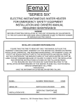
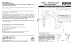
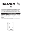
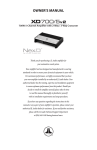
E X S ERIES
POLK AUDIO
5601 METRO DRIVE
BALTIMORE, MARYLAND 21215
(800)377-7655
POLK AUDIO EUROPE LTD.
TYTTENHANGER HOUSE
COURSERS ROAD
ST. ALBANS AL4 OPG
GREAT BRITAIN
TEL: 1727.827311
POLK AUDIO GERMANY
UNTERTUERKHEIMER STR. 24
D - 66117 SAARBRUECKEN
GERMANY
TEL: (49) 681 5800 888
http://www.polkaudio.com
"Polk Audio" and "The Speaker Specialists" are
trademarks of Britannia Investment Corporation used
under license by Polk Audio Incorporated.
Polk Audio
EX Series II Owner's Manual
POLK AUDIO – A HISTORY OF EXCELLENCE
ATTACH YOUR RECEIPT
HERE AND FILE FOR
FUTURE REFERENCE
X
Polk Audio was founded in 1972 by Matthew Polk and George Klopfer. Their dream was to
make speakers with the performance of the world’s best speakers, at a reasonable price. They
did so by applying scientific principles to speaker design and by concentrating solely on the
speaker business. That is how Polk became known as “The Speaker Specialists.”
Today Polk Audio is still headquartered in Baltimore, Maryland and is one of the world’s
largest manufacturers of home and car loudspeakers. Polk’s research has yielded over 20
patents for advances in loudspeaker performance and value. Polk speakers have earned the
praise of audio experts the world over, as well as dozens of awards for innovative, highquality design. Polk Audio speakers are sold in over 50 countries and in audio/video
specialist retail locations throughout the US.
Founders Matthew Polk and George Klopfer still work alongside 300 dedicated Polk team
members to bring you the best speakers you can buy.
A WORD FROM MATTHEW POLK
Dear Music Lover,
Thank you for purchasing Polk Audio speakers. Designing and building speakers is more
than just a business for the people of Polk Audio – it is our passion. We are all dedicated to
your complete satisfaction and delight.
Your new Polk speakers include the latest loudspeaker technology to assure outstanding
performance and unmatched quality. Please take a moment to read through this manual
for information on getting the greatest enjoyment from these fine instruments.
We make a wide variety of automotive loudspeakers, including factory replacements,
coaxials, component systems, tweeters and subwoofers. If you would like more information
on building the Polk car system of your dreams, consult your Polk Audio dealer or call our
Customer Service Department at 1-800-377-POLK (7655) from 9am to 5pm, Eastern Time,
Monday through Friday.
Sincerely,
Matthew S. Polk
Co-founder and Chairman
2
3
EX SERIES COMPONENT SYSTEMS FEATURES:
• Silk / Polymer composite tweeter dome for more accurate response and superior detail.
• Liquid Crystal Polymer driver cones for clear, well defined midrange, great bass and
ultra-high power handling.
• Rubber surround provides superior bass response and will not dry rot like foam surrounds.
• Magnetic fluid tweeter cooling ensures safe, reliable high SPL performance.
• Neodymium (NdFeb) magnets offer powerful magnetic energy from small magnets.
You get great sound and a speaker so small that’s it’s easy to fit and mount in a wide
variety of locations.
• Gold plated crossover terminals resist rust and corrosion for years of reliable performance.
GETTING STARTED
Please inspect each loudspeaker carefully. Notify your Polk dealer if you notice any
damaged or missing items. Keep the carton and packing material. They will do the best job
of protecting your speakers if they need to be transported. Check that you have the
following parts:
EX2540, EX2550, EX2560 and EX2565:
• 2 woofers
• 2 woofer grilles (except EX2565)
• 2 EX2500 tweeters with wires attached
• 2 crossover networks
• 2 tweeter flush mount cups
• 2 flush mount cup clamps
• 2 tweeter straight surface mount cups
• 2 tweeter angled surface mount cups
• speaker wires with connectors (attached)
• 4 machine screws – for flush mounting
• 16 sheet metal screws – for surface mounting (4); for crossover mounting (4);
for driver mounting (8)
• 12 speed nuts (8 driver mount; 4 surface mount)
• mounting template
• registration card
EX2500:
• 2 EX2500 tweeters with crossover and wires attached
• 2 tweeter flush mount cups
• 2 flush mount cup clamps
• 2 tweeter straight surface mount cups
• 2 tweeter angled surface mount cups
• 4 machine screws – for flush mounting
• 4 sheet metal screws – for surface mounting
• 4 speed nuts – for surface mounting
• registration card
Read this manual thoroughly first. If you have any doubts about your ability to execute any
of the installation steps, save yourself a lot of grief and contact a professional installer (your
Polk dealer is a good place to find one).
If you intend to do the installation yourself we assume that you possess some skill in the
proper use of hand and power tools. No matter how much installation experience you have,
it’s always a good idea to:
•
•
•
•
Read this manual thoroughly before you begin.
Plan your installation carefully.
Allow enough time to complete the installation without rushing.
Protect your car from unwanted scratches.
NECESSARY TOOLS
•
•
•
•
•
•
•
•
•
•
•
•
Phillips head screwdriver
Flat blade screwdriver or putty knife
Electric drill
1/4" and 1/8" drill bits
Magic marker for marking the cutout (new location installation only)
Metal cutting tool (hole saw), if you intend to cut metal
1 3/4" hole saw (for flush mount tweeter installation only)
Metal file
Soldering iron or a supply of solderless connectors
Safety glasses
Wire strippers and cutters
Crimping tool
Note: For EX2500 installation, please proceed to page 11.
4
5
INSTALLING THE COMPONENTS
;
EX2500 TWEETER
99.1
EX
AMP
(OPTIONAL)
RADIO
Crossover Network
CROSSOVER
(OPTIONAL)
MIDRANGE
FIG. 1
The EX System Crossovers
You will need to make wiring connections from your amp or radio to the crossovers and
from the crossovers to your mid/woofers and tweeters (see Figure 1). Choose crossover box
locations that are convenient for making these connections.
Your EX Series II crossovers have terminals which are clearly marked for wiring
connections. Refer to Figure 2 before making connections between your crossovers,
mid/woofers, and tweeters. The wires provided with your EX System have one red conductor.
Use this wire as the positive (+) lead and connect it to the positive (+) terminals on your
crossovers as well as to the positive (+) terminals of each speaker.
Installing The EX System Woofers in Factory Locations
Most cars have speaker grilles which blend with the rest of the car’s interior. Sometimes it is
difficult to determine how to remove these grilles to gain access to the speaker which you
intend to replace. If you have one of these grilles, you may want to consider using a
professional installer. On some cars, the grilles are held by screws or spring clips. The screws
will be obvious; however, the spring clips won’t be.
If there are screws, remove them, put them in a safe spot, and remove the grilles. To remove a
clip-on grill, use your flat-blade screwdriver or a putty knife to gently pry up the grille. If it
resists, back off and think again about the professional install. The cost of one of these can
sometimes be less than the cost of new door panels. Some grilles are integral parts of the door
panel and are not removable. In these cases you will need to remove the entire door panel to
gain access to the speaker location. This will usually require removal of door handles, window
winder mechanisms, and perhaps other parts such as door pulls and lock buttons.
1. Once you get the grille off, remove the factory speakers. Save the hardware. You may
be able to reuse it to mount your new speaker.
2. Attach speaker wires to the crossover woofer terminals. Attach the red wire to the
positive (+) terminal screw, and the black wire to the negative (-) terminal screw.
3. Slip the faston connectors onto the input terminals on the mid/woofer. Be sure to
attach the red wire to the positive (+) terminal, and the black wire to the
negative (-) terminal.
4. Using the hardware retained from the factory speaker or the screw clips supplied with
the EX speaker, secure your new speaker to the car panel.
;
AMP
WOOFER
EX
Crossover Network
TWEETER
FIG. 2
6
7
Installing the Mid/Woofers in Non-Factory Locations
EX2545 Special Instructions
If you have decided to install your EX Series II mid/woofers in locations other than those
provided by the automobile manufacturer, make certain that the location you choose is
clear of all obstructions, both in front of and behind the panel, before you proceed. Pay
particular attention to window mechanisms and any body panels critical to the structural
integrity of the vehicle. The mounting depths and cutout diameters of your EX Series II
mid/woofers are listed with all the other important specifications at the end of this manual.
The EX2545 has two break-away “tabs” to allow easy placement in tight locations
(see Figure 3). Remove only the tab(s) which allow the speaker to fit. Secure the speaker
with at least two opposing tabs.
1.
2.
3.
4.
5.
6.
A paper template for marking the cutout holes is in the speaker carton
Cut a hole in the panel
Using the paper template, mark the locations of the four screw holes
Drill the holes with a 1/8" bit
Attach the screw clips to the car panel at the hole locations
Attach speaker wires to the crossover woofer terminals. Attach the red wire to the
positive (+) terminal screw, and the black wire to the negative (-) terminal screw
7. Run wires from your amplifier or radio to the crossover. Attach these wires to the
crossover input terminals. Remember to route them away from low level electrical
cables and use grommets when passing through doors. Attach the red wire to the
positive (+) terminal screw, and the black wire to the negative (-) terminal screw
8. Remove the mesh grille from the grille frame and pass the wire through the grille frame
9. Slip the faston connectors onto the input terminals on the mid/woofers. Be sure to
attach the red wire to the positive (+) terminal, and the black wire to the negative
(-) terminal
10. Place the speaker into the grille frame and line up the screw holes with the screw
clips on the car panel
11. Secure the speaker/grille frame assembly to the car panel with the supplied screws
12. Place the mesh grille in the grille frame
8
FIG. 3
GRAY AREA BREAKS OFF
EX System Tweeters
One important advantage of component systems is their ability, when properly installed, to
improve the soundstage created by the music in your car. The soundstage is the musical
“picture” made up of the instruments and vocalists. The difference in the soundstage will be
dramatic depending on where you mount your tweeters. We recommend a simple experiment
that will help you decide the best spot for your tweeters in your car. Here are the steps:
1. Complete the installation of your entire system except for the EX2500 tweeters.
2. Connect the wires provided with your tweeters to the tweeter terminals on your
EX crossovers.
3. Without running the wires through doors or under upholstered panels, connect your
EX tweeters to these wires.
4. Have a friend sit in the passenger’s seat while you sit in the driver’s seat, with tweeters
temporarily taped in place.
5. With music playing, position the tweeters in different locations around the passenger
compartment, listening for the differences caused from these placements. We
recommend using vocals for this test. You will be able to determine in a short time
the best location for your tweeters.
9
The Polk EX2500 tweeter offers two mounting options for installation flexibility.
Mounting Option #1 – Surface mounting the EX2500 Tweeter
;
;
1. Using the base of the surface mount cup as a template, mark the two screw holes and
drill using a 1/8 inch drill bit. Drill a third hole (for the speaker wire) using the 1/4
inch drill bit.
2. Attach either surface mount cup (angled or straight) to the panel using #8 screws of
appropriate length for the panel.
3. Push the tweeter wires through the open area at the bottom of the cup and through
the 1/4" hole in the panel.
4. Connect wires from the tweeter terminals of the crossover, to the tweeter wires, using
the faston connectors. Connect the red wire strand to the (+) terminal of the
crossover tweeter output and to the red wire on your tweeters.
5. Mount the tweeter by snapping it into the mounting cup and turning the tweeter
clockwise, locking the tweeter in place.
FLUSH
MOUNT CUP
10
RETAINING
BRACKET
TWEETER
MOUNTING SCREW
Mounting Option #2 – Flush mounting the EX2500 Tweeter
1. Remove the panel on which you are going to mount the tweeter and check for proper
clearance behind it. The flush mount kit is 1/2 inch deep. Measure to make sure
there is sufficient depth behind the spot you choose.
2. Mark the center of the spot and cut a hole with the 1 3/4 inch hole saw attachment
for your power drill. Go slow. You can use a razor knife instead of a drill if you prefer.
3. Assemble cup, clamp, and machine screws loosely as shown in Figure 4.
4. Route wires through the round opening in the bottom of the cup.
5. Press the assembly into the 1 3/4 inch hole until the clamp edge is below the
mounting surface, then tighten the screw. The cup will clamp down to the surface as
the screw is tightened. In the case of a thick mounting surface, the legs of the clamp
can be bent outward by inserting a screwdriver through the holes in the cup while
still mounted.
6. Connect wires from the tweeter terminals of the crossover, to the tweeter wires, using
the faston connectors. Connect the red wire strand to the (+) terminal of the
crossover tweeter output and to the red (+) wire on the tweeter.
7. Mount the tweeter by snapping it into the mounting cup and turning the tweeter
clockwise, locking the tweeter in place.
PANEL
PANEL
FIG. 4
EX2500 Component Tweeter Hook-up
When purchased as a separate unit, the EX2500 tweeter includes a first order (6dB/octave)
crossover network integrated into the tweeter assembly. This high pass filter allows the
EX2500 to be used with other components. It is important to maintain correct polarity. The
red wire connects to the positive (+) amplifier terminal and the black to the negative (-)
amplifier terminal.
If your system contains an active crossover, you may bypass the in-line crossover and wire
the tweeter directly to the output terminals of an amplifier which has a high pass filter
(crossover) on its input. The minimum crossover point should be 2 kHz at 12dB per octave.
DO NOT USE THE TWEETER WITHOUT A CROSSOVER NETWORK. Damage to the tweeter
from thermal overload will result without the protection provided by a crossover and will
void your warranty.
11
POLARITY / BLENDING
LOW FREQUENCY CUT-OFF FOR SYSTEMS WITH SUBWOOFERS
If it seems that the tweeters and mid/woofers are not “blending” or working together in
harmony, try changing the polarity of both the tweeters by reversing the positive (+) and
negative (-) tweeter wires at the crossover. Reversing the absolute phase of the tweeters may
help the blending or integration of the system components, particularly if the tweeters and
mid/woofers are far apart.
If you have a subwoofer in your system, you may want to decrease the amount of bass going
to your mid-range speakers. This will get you better midrange sound and increase the power
handling. There are two ways to roll off the bass before it gets to the mid-range speakers.
One way is to use a “bass blocker”, a capacitor placed in series with the main input. The
other route is to use an electronic crossover device which allows filtering below 100 Hz or so.
AMPLIFIER POWER REQUIREMENTS
TECHNICAL ASSISTANCE OR SERVICE
Your speakers will work well with a variety of electronic components. As little as 20 watts per
channel will deliver adequate listening levels in most cars. If you have a noisy car or intend
to play your system at loud listening levels, more power is necessary to achieve the best
performance. Consult your Polk Audio dealer for specific recommendations.
If, after following the hook-up directions, you experience difficulty, please double check all
wire connections. Make sure that your electronic equipment is operating correctly by
hooking up another speaker to the speaker output. For example, if you are not getting
sound from the left channel speaker, connect the right channel speaker to the left output. If
you still get no sound from that side, the problem is in your amp or source electronics.
Should you isolate the problem to the speaker, contact the authorized Polk Audio dealer
where you made your purchase. Authorized Polk Audio dealers are the best source for advice
and assistance.
SAFE LIMITS OF OPERATION
Your Polk loudspeakers are made with the highest quality materials for years of trouble-free
performance. However, damage to loudspeakers can occur when an amplifier, regardless of
its wattage, is made to play at higher listening levels than its power can clearly produce
(usually beyond the “1 to 2 o’clock” position on the volume control).
This results in very high levels of audible distortion, originating in the amplifier, which
adds a harsh, gritty sound to the music. Contrary to popular belief, a speaker is more likely
to be damaged by trying to get too much volume from a low-powered amp or receiver than
from a high-powered one.
12
Polk Audio’s Customer Service Department at 1-800-377-POLK (7655) from 9am to 5pm,
Eastern Time, Monday through Friday. Please do not hesitate to call us if you have
questions about your speaker system.
13
EX SERIES II COMPONENT SPECIFICATIONS
EX SERIES II 1 YEAR WARRANTY
EX2565
two-way
system
EX2560
two-way
system
EX2550
two-way
system
EX2540
two-way
system
EX2500
tweeter
Driver complement
6 1/2"
Euro driver
with a 3/4"
tweeter
6 1/2"
driver
with a 3/4"
tweeter
5 1/4"
driver
with a 3/4"
tweeter
4"
driver
with a 3/4"
tweeter
3/4"(19mm)
dome
Mounting
diameter
5 9/16"
141mm
5 1/4"
132mm
4 7/8"
123mm
4 1/16"
103mm
N/A
N/A
Mounting depth
(top)
2 1/2"
2 1/8"
2 3/8"
1 13/16"
9/16" flush cup
Mounting depth
(bottom)
2 5/8"
2 3/8"
2 1/2"
2"
N/A
Power handling
(max)
180w
180w
150w
120w
100w
Nominal Imp.
4 ohms
4 ohms
4 ohms
4 ohms
4 ohms
Freq. response
45-22kHz
50-22kHz
70-22kHz
80-22kHz
4kHz-22kHz
Grille height
& diameter
N/A
N/A
1 1/8"
6 5/8"
7/8"
6 3/8"
3/4"
5 7/16"
N/A
N/A
Sensitivity (SPL)
92dB
92dB
92dB
91dB
92dB
Unit weight
2lbs.
1lb 12.5oz.
1lb 11oz.
1lb. 6oz.
1.2oz.
Crossover Point
4 kHz
4 kHz
4 kHz
4 kHz
4kHz
Type
Polk Audio, Inc. warrants the original purchaser only that this Polk Audio EX Series II
Product (the Product) will be free from defects in materials and workmanship for a period
of (1) one year from the date of original retail purchase from a Polk Audio Authorized
Dealer. However, this warranty will automatically terminate prior to the expiration of the
(1) one year period if the original retail purchaser sells or otherwise transfers the Product to
any other party. The original retail purchaser shall herein after be referred to as "you." To
allow Polk Audio to offer the best possible warranty service, please fill out the Product
Registration Card(s) and send them to the Factory at the address provided in the
Registration Card within (10) ten days of the date of purchase.
Defective Products must be shipped, together with a proof of purchase, prepaid insured to
the Authorized Polk Audio Dealer from whom you purchased the Product, or to the Factory
at the address given in this booklet. Products must be shipped in the original shipping
container or its equivalent; in any case the risk of loss or damage in transit is to be borne by
you. If, upon examination at the Factory or Polk Audio Authorized Dealer it is determined
that the unit was defective in materials or workmanship at any time during the Warranty
period, Polk Audio or the Polk Audio Dealer will, at its option, repair or replace this Product
at no additional charge, except as set forth below. All replaced parts and Products become
property of Polk Audio. Products replaced or repaired under this Warranty will be returned
to you, within a reasonable time, freight prepaid.
This Warranty does not include service or parts to repair damage caused by accident,
disaster, misuse, abuse, negligence, inadequate packing or shipping procedures,
commercial use, voltage inputs in excess of the rated maximum of the unit, cosmetic
appearance of the cabinetry not directly attributable to defects in materials or
workmanship, or service, repair, or modifications of the Product which has not been
authorized or approved by Polk Audio.
This Warranty is in lieu of all other expressed Warranties. If this Product is defective in
materials and workmanship as warranted above, your sole remedy shall be repair or
replacement as provided above. In no event will Polk Audio, Inc. be liable to you for any
incidental or consequential damages arising out of the use or inability to use the Product,
even if Polk Audio, Inc. or a Polk Audio Dealer has been advised of the possibility of such
damages, or any other claim by any other party. Some states do not allow the exclusion or
limitation of consequential damages, so the above limitation and exclusion may not apply
to you. This Warranty gives you specific legal rights which may vary from state to state.
This warranty applies only to Products purchased in the United States of America, its
possessions, and U.S. and NATO armed forces exchanges and audio clubs. The Warranty
terms and conditions applicable to Products purchased in other countries are available
from the Polk Audio Authorized Distributors in such countries.
14
15