1
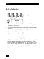
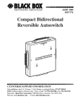
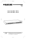
4x1 Compact VGA Switch
Model AC506A
March 2004
CUSTOMER
SUPPORT
INFORMATION
Order toll-free in the U.S. 24 hours, 7 A.M. Monday to midnight Friday:
877-877-BBOX
FREE technical support, 24 hours a day, 7 days a week:
Call 724-746-5500 or fax 724-746-0746
Mail order: Black Box Corporation, 1000 Park Drive, Lawrence, PA 15055
Web site: www.blackbox.com • E-mail: [email protected]
4x1 Compact VGA Switch
TRADEMARKS USED IN THIS MANUAL
(logo) are trademarks of Black Box Corporation. IBM
Black Box, and
is a registered trademark of International Business Machines Corporation.
Any other trademarks mentioned in this manual are acknowledged to be the
property of the trademark owners.
FEDERAL COMMUNICATIONS COMMISSION
RADIO FREQUENCY INTERFERENCE STATEMENT
This equipment generates, uses, and can radiate radio frequency energy
and if not installed and used properly, that is, in strict accordance with the
manufacturer’s instructions, may cause interference to radio
communication. It has been designed and found to comply with the limits
for a Class A computing device in accordance with the specifications in
Subpart B of Part 15 of FCC rules, which are intended to provide
reasonable protection against such interference when the equipment is
operated in a commercial environment. Operation of this equipment in a
residential area is likely to cause interference, in which case the user at his
or her own expense will be required to take whatever measures may be
necessary to correct the interference.
Changes or modifications not expressly approved by the party responsible
for compliance could void the user’s authority to operate the equipment.
This digital apparatus does not exceed the Class A limits for radio noise
emission from digital apparatus set out in the Radio Interference
Regulation of the Canadian Department of Communications.
EUROPEAN UNION DECLARATION OF CONFORMITY
This product complies with the requirements of the European EMC
directive 89/336/EEC
1
AC506A
Normas Oficiales Mexicanas (NOM)
Electrical Safety Statement
INSTRUCCIONES DE SEGURIDAD
1. Todas las instrucciones de seguridad y operación deberán ser leídas antes
de que el aparato eléctrico sea operado.
2. Las instrucciones de seguridad y operación deberán ser guardadas para
referencia futura.
3. Todas las advertencias en el aparato eléctrico y en sus instrucciones de
operación deben ser respetadas.
4. Todas las instrucciones de operación y uso deben ser seguidas.
5. El aparato eléctrico no deberá ser usado cerca del agua—por ejemplo,
cerca de la tina de baño, lavabo, sótano mojado o cerca de una alberca, etc.
6. El aparato eléctrico debe ser usado únicamente con carritos o pedestales
que sean recomendados por el fabricante.
7. El aparato eléctrico debe ser montado a la pared o al techo sólo como sea
recomendado por el fabricante.
8. Servicio—El usuario no debe intentar dar servicio al equipo eléctrico más
allá a lo descrito en las instrucciones de operación. Todo otro servicio
deberá ser referido a personal de servicio calificado.
9. El aparato eléctrico debe ser situado de tal manera que su posición no
interfiera su uso. La colocación del aparato eléctrico sobre una cama, sofá,
alfombra o superficie similar puede bloquea la ventilación, no se debe
colocar en libreros o gabinetes que impidan el flujo de aire por los orificios
de ventilación.
10. El equipo eléctrico deber ser situado fuera del alcance de fuentes de calor
como radiadores, registros de calor, estufas u otros aparatos (incluyendo
amplificadores) que producen calor.
2
4x1 Compact VGA Switch
11. El aparato eléctrico deberá ser connectado a una fuente de poder sólo del
tipo descrito en el instructivo de operación, o como se indique en el
aparato.
12. Precaución debe ser tomada de tal manera que la tierra fisica y la
polarización del equipo no sea eliminada.
13. Los cables de la fuente de poder deben ser guiados de tal manera que no
sean pisados ni pellizcados por objetos colocados sobre o contra ellos,
poniendo particular atención a los contactos y receptáculos donde salen del
aparato.
14. El equipo eléctrico debe ser limpiado únicamente de acuerdo a las
recomendaciones del fabricante.
15. En caso de existir, una antena externa deberá ser localizada lejos de las
lineas de energia.
16. El cable de corriente deberá ser desconectado del cuando el equipo no sea
usado por un largo periodo de tiempo.
17. Cuidado debe ser tomado de tal manera que objectos liquidos no sean
derramados sobre la cubierta u orificios de ventilación.
18. Servicio por personal calificado deberá ser provisto cuando:
A: El cable de poder o el contacto ha sido dañado; u
B: Objectos han caído o líquido ha sido derramado dentro del aparato; o
C: El aparato ha sido expuesto a la lluvia; o
D: El aparato parece no operar normalmente o muestra un cambio en su
desempeño; o
E: El aparato ha sido tirado o su cubierta ha sido dañada.
3
AC506A
Contents
1. Introduction ..........................................................page 5
1.1 General ................................................................page 5
1.2 Features ...............................................................page 6
2. Installation .............................................................page 6
3. Configuration and Operation...............................page 7
3.1 Modes of Operation..............................................page 7
3.2 Front Panel Switches ............................................page 7
3.3 RS-232 Control ....................................................page 8
4. Troubleshooting.....................................................page 9
Contacting Black Box ............................................page 10
Shipping & Packaging............................................page 10
5. Specifications .......................................................page 11
4
4x1 Compact VGA Switch
1. Introduction
1.1 General
The Model AC506A is a versatile, compact, high performance, solid-state,
4 input x 1 output, VGA video switch that can operate at resolutions of up
to 1600x1200.
The unit allows one monitor to be switched between 4 video sources. The
unit is housed in a small RFI shielded enclosure and is supplied with an
AC power adapter and a Serial (RS-232) control cable for connecting to a
PC or other serial control device.
The device terminates all video inputs and buffers the output to protect
signal integrity. The Model AC506A can drive video cables to 150 feet or
more. The input and output connectors are all HD15 Female.
There are several ways to control the AC506A. There are 4 buttons on the
front of the AC506A, each corresponding to a VGA input signal and there
is a serial port on the back of the AC506A. The serial port is used to
control the AC506A via a hyper terminal application on a PC. The unit
features Auto and Scan modes that can be invoked either from front panel
or by serial commands as well.
1.2 Features
q
q
q
q
q
q
q
Can be controlled manually, via Serial port, or automatically
based on video
Output can be blanked
User assigned priorities in Auto mode
Infinite switching cycle life
Can drive long cables
Terminates input signals and buffers the output for best
integrity
Includes power adapter and serial cables for control
5
AC506A
2. Installation
Figure 2.1
1.
Plug in the desired number of VGA sources to the VGA inputs on
the back of the AC506A.
2.
Connect an output device to the VGA output on the back of the
AC506A.
3.
Connect the included RS-232 cable to a PC if so desired.
4.
Connect the included power supply.
5.
Power on the included power supply
Plug-and-Play
DDC (Direct Data Channel) is a standard by which a compatible
monitor sends its identification and other parameters to a PnP
operating system such as Windows XP etc. The AC506A does not
switch the PNP signal lines to the PC. This means that, in some
instances, you may have to select a new monitor or video settings on
your PC. Also notice that most Notebook PC's have a special function
key to activate the external video output connector
6
4x1 Compact VGA Switch
3. Configuration & Operation
3.1 Modes of Operation
Auto Mode - This will select the VGA input with the highest priority
that has an active VGA signal.
Scan Mode - Will select each active VGA signal for a specified
number of seconds, 1-60, and then switch to the next active VGA input.
The AC506A can also be configured to scan the non-active VGA inputs as
well as the active VGA inputs.
Normal Mode - VGA inputs are selected based on front panel pushbutton selections.
The AC506A can only be in one of these modes at a time. You can specify
mode of operation either from the Serial port or from the front panel (by
pressing switch combinations simultaneously).
The Switch retains the last mode that it was in after power off and upon
power up, will enter the last mode that it was in.
3.2 Front-Panel Switches
The first function of the front panel buttons is to switch from one VGA
signal to another. Just press the button and the VGA signal you selected
will be displayed. If there is no VGA signal to be displayed then you will
see a black screen. The AC506A will enter Normal Mode any time a
single front panel button is pressed.
The second use of the front panel buttons is to put the AC506A into Auto
Mode. Press buttons 1 and 2 simultaneously and the AC506A will enter
Auto Mode.
The third use of the front panel buttons is to put the AC506A into Scan
Mode. Press buttons 3 and 4 simultaneously and the AC506A will enter
Scan Mode. The time interval between switching will be the time interval
last specified via the serial port. If no interval has been specified then the
default is 5 seconds. Whether or not to scan non-active VGA inputs along
7
AC506A
with active VGA inputs will be determined from the last user input via
serial port as well. If there has been no user input, the default is to not scan
the non-active VGA inputs.
3.3 RS-232 control via Hyper Terminal
To use the RS-232 control interface, start Hyper Terminal with the
following settings:
Baud rate: 4800
Data Bits: 8
Parity: None
Stop Bits: 1
Flow Control: None
This is what the menu will look like in Hyper Terminal..
-------------M E N U
-------------1 = #1 Input
2 = #2 Input
3 = #3 Input
4 = #4 Input
a = Auto Mode
s = Scan Mode
b = Blank
u = Un-Blank
p = Priorities
r = Reset
Figure 3.1
By pressing the number keys, "1", "2", "3", "4", the AC506A will switch
to that VGA input. This will also put the AC506A into Normal Mode.
Pressing "a" will put the AC506A into Auto Mode.
Pressing "s" will put the AC506A into Scan Mode. Before the AC506A
enters Scan Mode, you will be asked 2 questions. The first question will
be "Seconds between switching? (1-60)". To this question, you must input
a number between 1 and 60 then press enter. Any other input will cause
this question to be repeated. The second question will be, "Scan non-
8
4x1 Compact VGA Switch
active? (y/n)" You must answer this question with a "y" or a "n". Any
other input will result in this question being repeated.
Pressing "b" will blank all output from the AC506A until the un-blank
command is received.
Pressing "u" will un-blank the output from the AC506A if it was
previously blanked.
Pressing "p" will allow the user to input the priorities of each VGA input.
The user will be shown what the priority of each VGA input is and then
given the opportunity to change the priority. Priority can range from 1 to
4, 1 being the highest priority and 4 being the lowest priority. The user can
also press enter and the existing priority will be kept. The existing priority
will also be kept if the user enters a "0".
Pressing "r" will reset the AC506A with the factory defaults. The factory
defaults are Normal Mode, all priorities are 1, and the time interval
between scanning is 5 seconds.
4. Troubleshooting
1.
Fuzzy, blurry, or ghosting image
The VGA cables must be of high quality multi-coaxial construction. If you
are using long video cables in excess of 100 feet, the losses in the cable
could be a contributing factor, in which case, first reduce the refresh rate
to 60 HZ and if that is not enough, you may have to reduce the resolution
of the incoming video signal.
2.
The PC does not recognize a Plug-and-Play monitor
If the PC’s Operating System is setup to detect a plug-and-play monitor
(usually in Display Properties Advanced Settings), it may have trouble
finding a monitor. If the PC does not produce an image due to this, disable
the plug-and-play monitor detection in the PC’s operating system Display
Properties.
3.
Substituting power supplies
The AC506A relies on the power adapter that it comes with. Do not
substitute any other power supply or DC power source.
9
AC506A
Contacting Black Box
If you determine that your extender is malfunctioning, do not attempt to
repair the unit. Contact Black Box Tech. Support at 724-746-5500.
Before you do, make a record of the history of the problem. We will be
able to provide more efficient and accurate assistance if you have a
complete description.
Shipping and Packaging
If you need to transport or ship your extender:
• Package it carefully. We recommend that you use the original
container.
• Before you ship the units back to Black Box Corporation for repair
or return, contact us to get a Return Authorization (RA) number.
10
4x1 Compact VGA Switch
5. Specifications
Video Types
VGA through UXGA, RGBHV
Resolution
Up to 1600 x 1200 at up to 85 Hz
Bandwidth
DC to 250 MHz
Max. Distance Up to 150 ft. (50 m)
Connectors
HD15 female for input and both outputs; 3.5 mm Serial
Interfaces
Standard Analog VGA; EIA/TIA RS-232 Serial
Compliance
CE; FCC Part 15 Subpart B Class A, IC Class
Max. Altitude 10,000 ft. (3048 m)
Temperature Operating: 32 to 122°F (0 to 50°C);
Storage: –40 to +185°F (–40 to +85°C)
Humidity
Up to 95% non-condensing
Enclosure
Steel
MTBF
90,000 hours (calculated estimate)
Power
From utility-power (mains) outlet, through included
external power adapter. Output Voltage: 6v DC regulated
Center-Positive. Power :(2 watts Max)
Size
1.25” H x 2.75”W x 8.25” L (32 x 70 x 210 mm)
Weight
2 lbs. or 0.8 Kg (shipping)
11
AC506A
12
© Copyright 2004. Black Box Corporation..
All rights reserved.
1000 Park Drive
Lawrence, PA 15055-1018
724-746-5500
Fax 724-746-0746