1
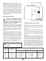
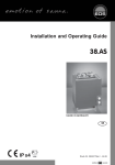
Installation and user guide
EMOTEC B6000
GB
IP x4
Druck Nr. 29342340en
GB
43.06
1
Table of Contents
General information concerning sauna bathing ..................................................... 3
Scope of delivery .................................................................................................. 4
General safety precautions ................................................................................... 4
Assembly of the control unit ................................................................................. 4
Wall mounting ............................................................................................ 4
Electrical connection ............................................................................................ 6
Connecting the sauna heater ................................................................................ 6
Connecting the sauna lamp .................................................................................. 7
Connecting the sensor lines ................................................................................. 7
Mounting the heater sensor .................................................................................. 7
Operation ............................................................................................................. 9
Button functions ......................................................................................... 9
Symbol description .................................................................................... 9
Unit initialization ....................................................................................... 10
Default parameters ............................................................................................ 11
Temperature indicator ............................................................................... 11
Heating time ............................................................................................ 11
Important notes when programming .......................................................... 12
Heating time limiter .................................................................................. 12
Changing the default temperature ............................................................. 13
Temperature setting ................................................................................. 13
Delayed start-up ....................................................................................... 13
Programming current time .................................................................................. 15
Programming fan operation ................................................................................. 15
The control unit switch ....................................................................................... 16
Error display ....................................................................................................... 16
Additional errors not displayed and their causes ...................................... 16
Technical data .................................................................................................... 17
Wiring diagram ................................................................................................... 18
Terms of warranty ............................................................................................... 19
2
GB
General information concerning sauna bathing
Dear customer,
Please note the variation in temperatures
in the cabin while sauna bathing. The
hottest area is directly under the cabin
ceiling, whereas there is a steady
temperature gradient towards the floor of
the cabin. Inversely, the relative humidity is
lowest directly under the cabin ceiling and
the highest on the cabin floor.
with purchase of this sauna control unit you
opted for a superior quality, high-tech
electronic device which was developed and
manufactured according to the highest
standards and guidelines.
Please note that an optimal interaction of
sauna cabin, sauna heater and sauna
control unit is mandatory for a pleasant
sauna climate in your cabin.
For safety reasons the temperature sensor
with the overheat safety shutdown is located
on the cabin ceiling above the heater , since
this is the hottest area in the cabin.
With this superior sauna control unit you
can "operate" your sauna system, and
thanks to the many individual
programming settings you will surely soon
find the setting that suits you best.
Therefore there will always be temperature
variations between the temperature sensor
of the control unit and the thermometer in
the cabin.
Perception in the sauna is very subjective,
therefore it really requires your own
perception, or that of your family to find the
most suitable settings.
For example, when pre-setting the cabin
temperature to 100°C, the thermometer
inside the cabin may easily show 85°C 90°C. This complies with the typical climate
inside the cabin.
By default the finnish sauna is preset to
95°C.
Always observe hygiene. Always use handor bathing towels, to avoid getting
perspiration on the wood.
The following operation instructions
describe how to pre-select "your" climate
in the cabin. Read these instructions
carefully, so that you quickly and easily find
your way though the programming process.
To avoid the perception of draft, you should
avoid using any ventilation system while
sauna bathing. It should only be used if
recommended by the cabin manufacturer.
Always make sure no objects are
located on the sauna heater before
starting the heating cycle.
GB
3
Package contents
assembly instructions, especially when
installing the temperature sensor. The
temperature above the oven is critical for
the temperature setting.
The
temperature can be held within operating
parameters and a minimal temperature
gradient inside the bench area of the
sauna cabin can be achieved only if unit
is assembled correctly.
(subject to change)
Included with the control unit are:
1. An heater-sensor board with overheat
shutoff protection, KTY-sensors with
sensor housing , two 3x25 mm
fastening screws and a 1,7 m long
sensor cable, red and white.
2. A plastic bag with three 4 x 20 mm
fastening screws and three spacer
tubes.
l The device may only be used as
intended as a control unit for sauna
heaters up to 9 kW. (Up to 36 kW when
combined with a power control unit)
3. A replacement overheat protection
module.
l
General safety precautions
lThis device has not been designed for
being used by persons (including
children) that are physically or mentally
handicapped or have sensory
disabilities. Moreover, it is not allowed
to use this device without sufficient
experience and/or knowledge, unless
these persons will be supervised by
persons responsible for their security
or in case they have been instructed how
to use this device.
Completely disconnect the control
unit from the electrical circuit, i.e. flip
all circuit breakers or the main circuit
breaker during each installation or repair.
l Please note the safety and installation
information from the sauna heater
manufacturer.
l Children are to be supervised in order
to make sure that they do not play with
this device.
l
Attention: It is forbidden to install
the control box in a closed switch
cabinet or behind a wooden panelling!
l
The electrical installation may be
done only by a qualified electrical
technician.
Assembly of the control unit
l You must comply with the regulations of
your power supply company and
applicable VDE regulations (DIN VDE
0100).
l
Wall mounting
Mount the control unit outside the sauna
cabin only. The most practical mounting
point would be the wall area onto which
the sauna heater is mounted on the inside,
except on the outside of the cabin. If
electrical conduits are present, mount the
control unit accordingly. To mount the
control unit, please follow these
instructions:
WARNING: Never attempt repairs
or installations yourself, as this
could result in serious injury or death.
Only a qualified technician may remove
the housing cover.
l Please note the dimensions in the
4
GB
3
3
Illust . 3.2
Illust. 1
Illust . 3.3
3. Hang the control unit onto the 3 mm
projecting screw. Insert the included
rubber sleeves into the openings on the
back side of the housing and lead the
electrical cable through these openings.
Screw the lower part of the housing onto
the cabin wall using the lower threaded
holes. (Illust. 4)
1. Remove the cover of the control unit. To
do this press the fastening tab inwards
with a flat screwdriver and remove the
housing top by pivoting it upwards
(Illust.1). Drill the threaded holes for the
included 4 x 20 mm wood screws
according to Illust. 2 & 3.1.
ca. 20 cm
mounting holes
eye level
upper mounting hole
2. Insert one of the wood screws into the
upper middle hole. This screw will be
the mounting point for the control unit.
Make sure the screw is projecting out
from wall about 3 mm. (Illust. 3.2)
feed-through
channel for sensor
lines
Illust. 3.1
feed-through channel
for lamp and fan
feed-through
channel for power
supply lead wire
feed-through
channel for oven
supply line
19 cm
eye level
ca. 34 cm
17,4 cm
Illust. 2
Illust . 4
GB
5
Lead wire for cabin lighting
Please note: If the sauna cabin is not
equipped with electrical conduits, the
electrical cables must be lead along the
outside of the cabin, preferably in one of
the recesses between the wood boards.
Therefore, you have to mount the control
unit farther away from the cabin wall, so
you can lead the cables into the unit. In
this case, use the included 3 spacer tubes
as shown in Illust. 3.3, which hold the lower
part at a distance.
Power supply lead wire
Electrical connection
The electrical connection may only
be done by a qualified electrical
technician under authority of the
regulations of the local power supply
company and those of the VDE.
Air intake opening
Connecting the sauna heater
In general, there can only be one permanent connection to the power supply network,
to include a device which allows the unit to
be disconnected from the power source with
a contact distance of at least 3 mm from all
terminals.
Assemble the sauna heater according to
the instructions provided by the
manufacturer in front of the air intake
opening.
Lead the silicon lines through the electrical
conduits to their respective terminals on
the control unit and connect them
according to the circuit diagram printed
there.
All electrical installations and connector
cables inside the cabin must be able to
withstand temperatures up to 140°C.
Please use the table below to determine
the required cable diameters for this task.
Please note: If no electrical conduits are
present, drill a hole with a diameter of 10
mm next to the air intake opening and lead
the heater control cables through this hole
to their corresponding terminals (U V W) in
the control unit. To protect the silicon lines
from external influences, install them in a
shielded fashion. For this task, use a fitting
cable or simple PVC conduit and lead the
silicon cable through it to the control unit.
Attach the power supply lead wire as shown
in Illust. 5 to the power supply terminals of
the control unit. Connection instructions are
printed directly in the control unit.
Warning: Always connect the
neutral conductor of the sauna
heater.
Connector
capacity in
KW
6
Appropriate for
cabin sizes
(in m³)
Illust. 5
minimum diameter in mm² (copper wire)
connection to 400 V 3N AC
safety fuse
Power supply lead wire
Connector cable
capacity in A
to the control unit
control unit for heater
4,5
4 - 6
5 x 2,5 mm²
5 x 1,5 mm²
3 x 16
6,0
6 - 10
5 x 2,5 mm²
5 x 1,5 mm²
3 x 16
7,5
8 - 12
5 x 2,5 mm²
5 x 1,5 mm²
3 x 16
9,0
10 - 14
5 x 2,5 mm²
5 x 1,5 mm²
3 x 16
GB
Mounting the oven sensor
Connecting the sauna lamp
1. Mount the oven sensor in cabins up to
2 x 2m according to Illust. 6 and 7, in larger
cabins according to Illust. 6 and 8.
The sauna lamp must be splashproof (by
Standard IPx4) and resistant to ambient
temperature. The sauna lamp can be
mounted anywhere except in the area of
the rising hot air above the oven.
Connecting the sensor lines
35 cm
19 cm
You should not install sensor and power
supply lines together, or lead them through
the same conduit. This can lead to
interferences in the electronics, such as
"fluttering" in the relays. If it is absolutely
necessary to install them together, or the
wire is longer than 3m, you should use a
shielded sensor line such as the LIYLY-O x
0.5 mm²).
Illust. 7
Illust. 8
Connect the shielding to mass in the control
unit. This is the left contact on the
corresponding sensor connector terminals.
2. Drill a hole to lead the cable through,
preferably through the middle of one of
the wooden boards.
Please note that the following
measurements are based on values
provided by the unit quality assurance by the
European Standard EN 60335-2-53. In
principle, you must mount the oven sensor
where temperatures are expected to be the
highest. Illust. 6 gives you an overview of the
mounting point of the sensor.
3. Lead the sensor cable through the
drilled hole and attach it to the sensor
line according to Illust. 9.
Hole
20 cm
Sauna ceiling
Sensor housing
Sensor line
Center sensor
housing on middle
section
Limiter Sensor
Terminals in
the control unit
Illust. 9
Illust. 6
GB
7
4. Attach the lines for the shutoff (white)
and the temperature sensor (red)
according to Illust. 10 to the sensor
board. Then insert the sensor board into
the housing.
red
red
white (Limiter)
Housing
white (Limiter)
Sensor
Ô
Sensor
board
Illust. 10
5. After you are finished installing and have
made sure the control unit is functioning
properly, check the line for overheat
shutoff protection for short circuits. To
do this, release one of the white lines in
the sensor housing. The safety relay of
the control unit should now fall; i.e. the
heating circuit should now be
interrupted.
8
GB
Operation
Button Functions
Mode
Operating switch
on - off
Lamp
on - off
Program
button
Selection
buttons
Illust. 11
Symbol description
F1
Time
P3
Heating (dry)
P1
Pre-selected time
P4
Ventilation function
P2
Heating time
GB
9
Unit initialization
After checking all connections once more,
connect the unit to the power supply by
switching on the fuse and the main switch.
On the display appears
and the clock symbol begins to blink.
After a short time (30 seconds) you can
start with programming.
12:00
You may now set the current time using the
and
buttons during the blinking of
the clock symbol.
Mode
To accept the selected time, press the
MODE-button until the selected time
begins to blink.
Mode
Briefly F1 appears on the display.
After that, the current time is displayed and
the unit is ready for operation.
F1
Turn on the unit by pressing the left
button.
Simultaneously, this turns on the cabin
lighting and the backlit display.
Mode
Display readout
10
GB
Default parameters
Finnish sauna operation
20:03
After switching on the unit, the display
alternates between the time of day and the
remaining heating time.
05:58
Temperature indicator
The temperature is displayed on the righthand side of the display by a thermometer
symbol.
preselected
temperature
An arrow on the right side of the
thermometer displays the pre-selected
temperature.
The colored area of the thermometer
displays the current temperature in the
cabin.
Current
temperature in
cabin
During the heating cycle the thermometer
rises to the preset temperature. Once
reached, the control phase begins.
Heating time
By default the heating time is limited to 6
hours. After 6 hours, the unit will shut down
for safety reasons.
20:03
The remaining heating time alternates with
the current time of day on the display.
05:58
GB
11
If you wish to end your sauna bath
prematurely, press the
button.
Mode
The symbol on the display then disappears.
Important notes when programming
Every modification of the preset parameters
must be confirmed by pressing the "MODE"
button.
If you do not press the "MODE" button,
the unit will automatically default back to
the previous parameters.
If you do not touch the unit for a longer
period of time during programming, the
display will default back to standard and
the illumination will cease after a short
time.
Heating time limiter
If you wish to individually set the heating
time for your sauna system, press the
"MODE" button and choose P2 using the
selection buttons
or .
P
Press the "MODE" button again.
2
Now you may set the heating time using
the selection buttons.
03:00
Confirm your input by holding the "MODE"
button pressed continuously until the new
heating time and the symbol expire on the
display.
Afterwards P2 shortly appears, then the
display returns to default readout. The
maximum heating time now matches the
entered value until changed again (re-start
required).
12
GB
Changing the default temperature
Temperature setting
By default the temperature for Finnish
operation is set to 95°C. To change this
parameter, press the "MODE" button.
P1
P1 then appears on the display in the
programming area.
P3
button repeatedly until P3
Press the
and the heating symbol appear on the
display, and confirm this with the "MODE"
button.
90
The thermometer symbol appears, and the
heating symbol begins to blink.
Use the selection buttons
and
to set
the temperature. The arrow on the
thermometer symbol displays the selected
temperature level.
Finally, press and hold the "MODE" button
until the heating symbol besides the entered value begins to blink.
This confirms the entered value.
Delayed startup
, you can set your
Using the time preset
sauna system to start up within 24 hours.
Always check for objects on the
sauna oven before starting up the
sauna. Fire hazard!
P1
To select an alternate start-up time, press
the "MODE" button. The selection symbol
P1 appears on the display.
15:07
Press the "MODE" button again and you
see the actual start-up time.
GB
13
Using the selection buttons
and
you
can now set heating time.
Please consider, though, that the cabin
needs 40-50 minutes for warming up, to
create a pleasant climate in the cabin. For
example, if you wish to take your sauna
bath at 6 p.m., then you should set the
startup time to 5:10 p.m.
17:10
Confirm the selected time by holding the
"MODE" button. P1 briefly appears on the
display.
As long as P1 is shown on the display,
P1
button to start the delayed
press the
start-up sequence.
After a short time, the display alternates
between current time and startup time. The
display illumination goes out.
20:03
When the pre-selected start-up time is
reached, the sauna switches itself on.
After the designated heating time it then
shuts itself back off automatically.
17:10
You are now familiar with the program
parameters needed for a sauna bath.
With this sauna control unit you may also
personalize the settings for your sauna
system.
Once you have chosen these settings, they
will be applied after every restart.
These settings are altered on the "F"-level,
i.e. "F" appears for each corresponding
function selection on the display.
14
GB
Programming current time
To reach this program level, press the
"MODE" button and the
button simultaneously until F1 is displayed, as well as
the clock symbol.
F1
You can change the time with function F1.
Confirm with the "MODE" button and the
previously set time begins to blink with the
clock symbol.
20:03
and
Set the current time using the
buttons (e.g. when adjusting daylightsavings time).
Confirm your selection by pressing and
holding the "MODE" button, until the
entered value begins to blink.
F1 briefly appears on the display, then the
unit returns to its default readout.
F1
Programming fan operation
This control unit lets you operate a fan.
By factory default, "no fan operation" is
specified.
To program the fan function, first press the
"MODE" button to reach the programming
mode.
P1 then appears on the display.
Press the
button repeatedly to reach
the program level P4. The fan symbol
appears on the display.
P1
Confirm by pressing the "MODE" button.
P4
A "0" appears on the display (no fan
button, you
operation). By pressing the
can set a "1" (fan operation).
Confirm your selection by pressing the
"MODE"..button. On the display appears
shortly P4, then the unit returns to its default
readout and in set value "1" the fan symbol
appears on the display.
without symbol
with
GB
= no fan operation
symbol = fan operation
15
The control unit switch
The control unit switch can be found on the
top end of the unit. Using this
switch, you can isolate the electronics from
the mains supply in case of a breakdown.
Please note that operating the control unit
switch returns all settings to the factory
settings.
Control unit switch
= unit
switched
on
In case of breakdown, press the control
unit switch on the left part of the rocker to
the first position (switch position 0). The
unit is now completely switched off.
= unit
switched
off
In order to switch on the light in the sauna
when the unit is switched off, press on the
left part of the rocker to the second position
(switch position II).
= light
switched
on
In order to put the unit back into operation,
switch back to the starting position (switch
position I).
Error display
To quickly diagnose possible errors, use the error code explanation below to ascertain the
type of error.
Error code
Error
E 100
temperature sensor interruption/disconnection
E 101
temperature sensor short circuit
E 211
overheat safety shutoff interruption/disconnection
The warning symbol
blinks whenever an error message is displayed, so you may
easily recognize an error.
Additional errors not displayed and their causes:
Blank display - display not backlit
Check the power supply! All three phases L1, L2, L3 must be connected to 230 V AC.
Check all fuses.
Check the microfuse on the circuit board. You may use a 100 mA / T type fuse for
replacement.
16
GB
Technical data
Rated voltage:
400 V 3 N 50 Hz AC
Schaltleistung:
max 9 kW resistive load (AC 1 operation)
upgrade to 36 kW possible through connection to power
control units
Heating time shut-off:
6h
Display:
Protection type:
LCD, backlit
IPx4 in accordance with DIN 40050 (German Standards
Institution), splashproofing
Control range, sauna operation: 30 to 115°C
Sensor system:
KTY-Sensor with overheat shutoff protection at 139° C
Control characteristics:
digital two-step control of -20° C - max. cab temperature
Fan capacity::
Light:
max. 100 W, max. 450 mA (only fan without capacitor)
max. 100 W, max. 450 mA (only ohm resistive load)
Fuse protection on the light and the ventilation can
be a maximum of 1A delay action. There is a danger
of fire if greater fuse protection is used!
Error display:
blinking warning triangle and error code on LCD
Environmental temperature:
0°C to +40°C
Storage temperatures:
-20°C to +70°C
GB
17
GB
W
W
P max 9.0 kW
V
V
N
L1
400 V 3N AC 50 Hz
L2
L3
U
U
N
N
N
N
L1
L2
L3
S2
S1
light
S1 light fan
power
control unit
fan
DC 12 V / 24 V
limiter
w
AC 400 V 3N
sensor
139 ˚C
r
18
r
Sauna control unit EMOTEC B6000
KTY 11/5
Wiring diagram
w
$
Service address:
EOS-Werke Günther GmbH
D-35759 Driedorf, Germany
Tel. +49 (0) 27 75 8 22 40
Fax +49 (0) 27 75 8 24 55
e-mail: [email protected]
Internet: www.eos-werke.de
Guarantee
-
The period of warrenty starts from the date of purchase
and lasts up to 2years for commercial use and 3 years
for private use.
Please keep this address together with the
installation guide in a safe place.
In order for us to be able to answer your
questions in a fast and competent manner,
please always state the data indicated on
the type plate like type name, item number
and production number.
-
Always include the completed warrenty certificate when
returning equipment.
-
The warrenty expires for appliances which have been
modified without manufacturer’s explicit agreement.
-
Damages caused by incorrect operation or handling
through non-authorized persons are not covered under
the terms of warranty.
-
In the event of a claim, please indicate the serial number
as well as the article code number and type name with
expressive description of the fault.
-
This warrenty covers damaged parts but no defects due
to wear and tear.
The guarantee is taken over according to the legal
regulations at present.
Manufacturer’s warrenty
In case of complaint please return the equipment in its
original packaging or other suitable packaging (caution:
danger of transport damage) to our service department.
Always include the completed warrenty certificate when
returning equipment.
Possible shipping costs arising from the transport to and
from point of repair cannot be borne by us.
Outside of Germany please contact your specialist
dealer in case of warranty claims. Direct warranty
processing with our service department is in this case not
possible.
Equipment start-up date:
Stamp and signature of the authorized electrician:
Attention!
Dear customer,
according to the valid regulations, the
electrical connection of the sauna heater
and the control box has to be carried out
through the specialist of an authorized
electric shop.
We would like to mention to the fact that
in case of a warrenty claim, you are kindly
requested to present a copy of the invoice
of the executive electric shop.
GB
19