1
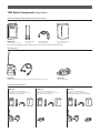
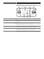
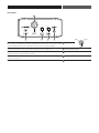
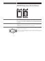
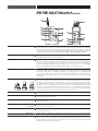
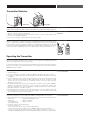
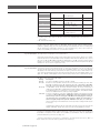
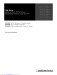
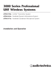
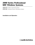
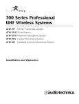
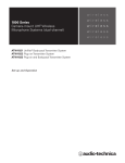
wireless
1800 Series
Camera-mount UHF Wireless
Microphone Systems (single-channel)
wireless
wireless
wireless
wireless
ATW-1811 UniPak® Body-pack Transmitter System
ATW-1812 Plug -on Transmitter System
ATW-1813 Plug-on and Body-pack Transmitter System
Set-up and Operation
2
This device complies with part 15 of the FCC Rules. Operation is subject to the condition that this device does not cause harmful interference.
This device complies with INDUSTRY CANADA R.S.S. 210, en conformité avec IC: RSS-210/CNR210.
Operation is subject to the following conditions: 1) This device may not cause harmful interference and 2) this device must accept any interference
received, including interference which may cause undesired operation. Changes or modifications not expressly approved by Audio-Technica could
void your authority to operate this equipment.
Notice to individuals with implanted cardiac pacemakers or AICD devices:
Any source of RF (radio frequency) energy may interfere with normal functioning of the implanted device. All wireless microphones have
low-power transmitters (less than 0.05 watts output) which are unlikely to cause difficulty, especially if they are at least a few inches away.
However, since a “body-pack” mic transmitter typically is placed against the body, we suggest attaching it at the belt, rather than in a shirt pocket
where it may be immediately adjacent to the medical device. Note also that any medical-device disruption will cease when the RF transmitting
source is turned off. Please contact your physician or medical-device provider if you have any questions, or experience any problems with the
use of this or any other RF equipment.
CAUTION! The circuits inside the receiver and transmitter have been precisely adjusted for optimum performance and compliance with federal
regulations. Do not attempt to open the receiver or transmitter. To do so will void the warranty, and may cause improper operation.
Warning: To prevent fire or shock hazard, do not expose this appliance to rain or moisture.
Attention: Pour prévenir feu ou choc électrique, ne pas exposé l'appareil à la pluie ou à l'humidité.
About RF Interference
Please note that wireless frequencies are shared with other radio services. According to Federal Communications Commission regulations,
“Wireless microphone operations are unprotected from interference from other licensed operations in the band. If any interference is received
by any Government or non-Government operation, the wireless microphone must cease operation...”
If you need help with operation or frequency selection, please contact your local dealer or Audio-Technica. Extensive wireless information
also is available at www.audio-technica.com.
Contents
Components and System Configurations
System Features
Quick Overview of System Operation
Receiver Controls
Operating the Receiver
Transmitter Controls
Operating the Transmitter
Tips for Best Results
Available Accessories
Specifications
Warranty
3
4
5
6
9
10
11
13
14
15
16
3
1800 Series Components (single-channel)
Receiver and Included Components/Accessories
ATW-R1810
Single-channel receiver
Two detachable
antennas
18" output cable,
TA3F to XLRM
Pouch with belt clip
(holds receiver)
Note: All model numbers have an additional letter at the end to indicate frequency band.
Transmitters
ATW-T1801
UniPak® transmitter with included omnidirectional lavalier microphone
ATW-T1802
Plug-on transmitter
System Configurations
ATW-1811
Camera-mount UHF Wireless
Microphone System (single-channel)
with Body-pack Transmitter
ATW-1812
Camera-mount UHF Wireless
Microphone System (single-channel)
with Plug-on Transmitter
ATW-1813
Camera-mount UHF Wireless
Microphone System (single-channel)
with Body-pack and Plug-on Transmitters
4
System Features
(single-channel)
•
True Diversity operation for resistance to multi-path interference and dropouts
•
UHF reception with 996 frequencies selectable in 25 kHz steps
•
Automatic frequency scanning for easy selection of open channels
•
Tone Lock™ squelch system eliminates interference when transmitter is off
•
Balanced output on receiver allows connection to a balanced microphone-level
input on camera, mixer or amplifier
•
Headphone monitor output with independent level control
•
Battery fuel-level indicators on transmitters and receiver
•
Soft-touch controls for easy frequency selection
•
LCD frequency and battery status display with backlight on receiver and
transmitters
•
Antenna and AF Peak LED indicators
•
Compact receiver ideal for on-camera use
•
Transmitters operate in low or high transmission modes to conserve battery
life/maximize power
•
Easy, user-friendly operation
•
Clear, natural sound quality
•
Powered by AA batteries or external 12V DC power (not included)
•
System components of the 1800 Series and 3000 Series UHF Wireless Systems
can be used interchangeably*
* NOTE: The 1800 Series offers operating frequencies in 25 kHz steps, while the 3000 Series
offers operating frequencies in 125 kHz steps. This means that not every frequency
selectable on the 1800 Series components will be selectable on the 3000 Series components.
Set each transmitter-receiver pair to identical frequencies.
5
Quick Overview of System Operation
Thank you for purchasing this Audio-Technica 1800 Series Single-channel Camera-mount
UHF Wireless Microphone System. All 1800 Series Single-channel systems are designed
primarily to be used with video cameras, with the ATW-R1810 Receiver mounted on a camera
and connected to the camera's audio input; they may also be used with other components
equipped with microphone-level input.
First, insert batteries. (See Receiver Battery Installation, page 8.) Note: The ATW-R1810
Single-channel Receiver also functions without batteries if connected to an external
power supply (12V DC source, 500 mA nominal current, not included).
Next, attach the antennas to the antenna input jacks, and mount the ATW-R1810 Receiver to
your camera (mounting hardware not included); or use the included pouch with belt clip to
attach the ATW-R1810 to your belt. Connect the output cable to the ATW-R1810 and your video
camera (or audio mixer). (See Output callout, page 7 ).
Turn the ATW-R1810 on: Press and hold the Power/Set button until the Power LED lights red.
Select an operating frequency. (See Selecting Frequencies on your Receiver, page 9.)
NOTE: Transmitter-Receiver pairs must be set to identical frequencies.
IF your system is equipped with a UniPak® Body-pack Transmitter and lavalier microphone:
Plug the included lavalier microphone into the UniPak® body-pack transmitter and position
microphone on your subject about six inches below the chin. Anticipate movements that may
cause the microphone to rub against or be covered by clothing, and position the microphone to
avoid it. Turn the power on (See Operating the Transmitter, page 11). Select a frequency and
choose other settings. (See Operating the Transmitter and How to Set Frequencies on your
Transmitter, page 11.)
IF your system is equipped with a Plug-on Transmitter: Attach a microphone (dynamic or
condenser) to the Plug-on Transmitter's input connector (See Microphone Input, page, 10 ).
Turn the power on (See Operating the Transmitter, page 11 ). Select a frequency and choose
other settings. (See Operating the Transmitter and How to Set Frequencies on your Transmitter,
page 11.)
6
ATW-R1810 Single-channel Receiver Controls (front panel)
2
6
1
3
5
2
4
LCD 1 Liquid Crystal Display shows battery status and frequency settings.
Antenna Input Jacks 2 BNC-type antenna connectors. Attach the antennas to the antenna input jacks. Make certain
that during operation there is a clear open-air path between the receiver antennas and the
transmitters.
Diversity Indicators 3 True Diversity operation: two antennas feed two completely independent RF sections on the
same frequency; automatic logic circuitry selects the superior signal.
Diversity Indicators A and B show which tuner has the better reception and is in operation.
Power / Set Button 4 Turns the unit on and off. Use with the Up/Down arrows to choose operating frequencies
manually or automatically (using your choice of three automatic scan groups).
Power/Peak LED 5 Indicates when the unit is on. Also indicates receiver overload by turning off; too much signal
will cause blinking LED (off during peaks). To correct overload, adjust audio gain on transmitter.
(See Audio Input Level (Gain) Adjustments on your transmitter, page 12.)
Up/Down Arrows 6 Press Up or Down arrows, in conjunction with the Power/Set button, to choose operating
frequencies manually or automatically (using your choice of three automatic scan groups).
7
(rear panel)
7
10
8
9
11
PIN 1
Balanced Audio Output Jack: TA3M-type connector. Pin 1: ground (shield); Pin 2: “audio +”; 7 Output
Pin 3: “audio –”. A standard 2-conductor shielded cable can be used to connect the receiver
output to a balanced microphone-level input on a camera, mixer or integrated amplifier.
Controls the output level of the receiver. Turn clockwise to increase output level.
8 Receiver Level Control
The level control (volume control) for headphones is independent of other level controls. Turn to 9 Monitor Level Control
the right to increase output (turn up the volume).
You may connect the unit to an external power supply (12V DC source, 500 mA nominal 10 DC Input
current, not included.)
3.5 mm TRS headphone jack.
11 Monitor Output
7
PIN 3
PIN 2
8
ATW-R1810 Single-channel Receiver Batteries
Battery Selection Each ATW-R1810 Single-channel Receiver uses four 1.5V AA batteries, not included. Alkaline
type is recommended. Always replace all batteries. Make certain the receiver power is Off
before replacing batteries. Note: The ATW-R1810 receiver also functions without batteries
if connected to an external power supply (12V DC source, 500 mA nominal current,
not included).
Battery Installation 1. Open the battery compartment door by pushing the catch back.
2. Observe correct polarity as marked and carefully insert four fresh 1.5V AA alkaline batteries
(see above).
3. Replace the door, making certain the latch clicks securely in place.
Battery Condition Indicator After the batteries are installed, turn the power on. The small red power-on LED (see a at left )
should light and the LCD window should come on. If this does not happen, the batteries are
b
installed incorrectly or they are dead.
The receiver's “fuel gauge” battery indicator (see b at left) displays a maximum of four bar
segments. When LCD flashes LOW.BAT, the batteries should be replaced immediately to
ensure continued operation.
a
9
Operating the Receiver
NOTE: Transmitter-Receiver pairs must be set to identical frequencies.
Overview…
Selecting Frequencies
1. To turn the receiver on, press and hold the Power/Set button until the Power LED lights, and on your Receiver
the LCD window comes on (about 2-3 seconds). The operating frequency will show in the
window after the power-up sequence.
2. Press the Power/Set button to enter the Frequency Selection Menu mode; the word
“MENU” will appear in the upper left corner of the LCD window.
3. Use the Up/Down arrows to cycle through functions:
– first arrow up is Automatic Scan Group 1;
– second arrow up is Automatic Scan Group 2;
– third arrow up is Automatic Scan Group 3;
– fourth arrow up is Quit, allowing exit from Menu mode.
1. Press Power/Set button to enter Menu mode. The word “MENU” will appear in the upper Setting Receiver Frequency Manually
left corner of the LCD window. The current frequency will be displayed in the LCD window.
Press Power/Set button and frequency will begin to flash and the word “EDIT” will appear
above the frequency display; use up and down arrows to adjust the frequency. Frequency
changes in 25k steps. To increase scroll speed, hold the up or down arrow for more than
4 seconds.
2. When you arrive at desired frequency, press and hold the Power/Set button until the word
“STORED” appears. Frequency (which appears on the screen) is now set.
3. To “back out” of the Manual Frequency Set mode without making a frequency choice,
simply press the Power/Set button once to exit the menu. The word “ESCAPE” will appear
in the window, and no changes in frequency setting will be made; the receiver's audio
output will again be enabled.
1. Press the Power/Set button to enter the Frequency Selection Menu mode; the word Using the Automatic Scan Function
“Menu” will appear in the upper left corner of the LCD window.
to Set Receiver Frequency
2. Use the Up or Down arrow to reach Scan 1, Scan 2, or Scan 3. Press the Power/Set button
once to select one of these three Scan groups. The word “SCAN1”, “SCAN2” or “SCAN3”
will flash in the LCD window.
3. Press the Up or Down arrow to begin the scan. Press the Up arrow to scan up from the
lowest frequency in the group; press the Down arrow to scan down from the highest
frequency in the group
4. The first available frequency will flash in the LCD window. To activate this frequency
selection, press and hold the Power/Set button until the word “STORED” appears in the LCD
window.
5. If you do not wish to use the frequency found, you may press the Up or Down arrow. The Up
arrow with scan upwards, the Down arrow will scan downwards, from the frequency you are on.
6. To “back out” without making a frequency choice, simply press the Power/Set button once
to exit the menu. The word “ESCAPE” will appear in the window, and no changes in frequency
setting will be made; the receiver's audio output will again be enabled.
10
ATW-T1801 UniPak® Body-pack &
ATW-T1802 Plug-on Transmitter Controls
1
5
2
4
6
7
POWER
MUTE
SET
12
8
11
10
3
7
SET
8
POWER/MUTE
9
ATW-T1801 UHF TRANSMITTER
3
2
6
11
Antenna 1 The ATW-T1801 UniPak® body-pack transmitter includes a field-replaceable flexible antenna. For
best results, allow the antenna to hang freely and full length from the bottom of the transmitter.
If the received signal is marginal, experiment with different transmitter positions or try repositioning the receiver. Since the transmitter antenna simply screws in, check to make certain it is
snugly attached (finger-tight). Do not change the length of the transmitting antenna.
Power-on LED 2 Green light indicates power is on and un-muted; red light indicates that audio is muted.
The light will blink when the batteries are low.
LCD 3 Liquid Crystal Display presents setup and operating information. The LCD in the transmitters is
designed for greatest contrast and best viewing with the window rotated somewhat away from
the viewer (about 30 degrees), not straight-on, for a more convenient holding/viewing
position. The display is illuminated with a backlight when you press Set to access transmitter
functions. The backlight will automatically turn off within a set period of time.
Audio Input Jack 4 Connect an audio input device (microphone or guitar cable) to the audio input jack on the bottom
of the ATW-T1801 UniPak® Body-pack Transmitter. A number of Audio -Technica professional
microphones and cables are available separately, pre-terminated with a compatible input
connector (see page 14 ). The cable connector latches automatically when inserted into the
transmitter jack. To unlatch and remove the connector, pull up on the connector’s knurled
metal collar.
a
Microphone Input 5 The ATW-T1802 plug-on transmitter has a 3-pin XLRF-type input connector with a locking collar.
Use either a dynamic or a condenser microphone. The transmitter provides power to condenser
microphones rated to operate on 12V phantom power or less. To attach the microphone, rotate
the threaded locking collar fully clockwise (“down”) until it reaches the transmitter housing (see
a at right ). Press the microphone and transmitter together (see b at right ). Rotate the threaded collar “up” until it is firmly against the end of the mic (see c at right ). Make certain the mic
is securely attached before use. To detach the microphone, reverse the steps above. Always
c
b
loosen the threaded collar fully before attempting to disconnect the mic.
Power/Mute Button 6 For on/off and mute functions.
Up/Down Arrows 7 Press Up or Down arrows, in conjunction with the Set button, to choose operating frequencies
and access transmitter functions.
Set Button 8 Use in conjunction with the Up/Down arrows, to choose operating frequencies and access
transmitter functions.
Sliding Control Cover 9 This 3-position sliding cover on the body-pack transmitter’s control panel prevents accidental
(3-position)
shut-off or channel-switching.
Sliding Control Cover 10 This sliding cover on the plug-on transmitter’s control panel helps to prevent accidental shut-off
or channel-switching.
Battery Door 11 Open by sliding the catch down (on body-pack) or pushing in direction of arrow (on plug-on transmitter).
Mounting Clip 12 The ATW-T1801 UniPak® transmitter’s mounting clip may be installed with the case positioned
either “up” or “down,” depending upon which is preferred for the application. To turn the clip
around, spring the ends of the clip out of the two holes on the sides of the transmitter case and
reinstall it facing in the opposite direction.
11
Transmitter Batteries
ATW-T1801
ATW-T1802
Each transmitter uses two 1.5V AA batteries, not included. Alkaline type is recommended. Battery Selection
Always replace both batteries. Make certain the transmitter power is Off before replacing batteries.
1. Open the battery compartment door by sliding the catch down (on body-pack) or pushing in Transmitter Battery
direction of arrow (on plug-on transmitter).
Installation
2. Observe correct polarity as marked on the metal contacts on the door and carefully insert
two fresh 1.5V AA alkaline batteries.
3. Close the door, making certain the latch clicks securely in place.
POWER
MUTE
SET
SET
POWER/MUTE
ATW-T1801 UHF TRANSMITTER
After the batteries are installed, turn the power on by pressing and holding the Power/Mute Battery Condition
button. The small power-on LED ( see a at left ) should light green and the LCD window should
come on. If this does not happen, the batteries are installed incorrectly or they are depleted.
a
The transmitter’s “fuel gauge” battery indicator in the LCD displays a maximum of four bar segments. When it flashes “LOW.BAT”, the batteries should be replaced immediately to ensure
continued operation. (Additionally, the power-on LED will flash when the batteries are low.)
Operating the Transmitter
To turn the transmitter on, press and hold the Power/Mute button until the power indicator Turning your Transmitter On & Off
lights green, and the LCD window comes on (about 1-2 seconds). The operating frequency will
show in the window after the power-up sequence.
To turn the transmitter off, press and hold the Power/Mute button again, until the power indicator
and the LCD window are extinguished (about 1-2 seconds). The LCD window will show
“PWR.OFF” before shutdown.
NOTE: Set your transmitter and receiver to identical frequencies.
How to Set Frequencies
on your Transmitter
1. Turn transmitter on.
2. Press the Set button once and the small word “MENU” will appear above the frequency.
3. Press the Set button again and the small flashing word “EDIT” will appear to the right
of “MENU”.
4. Use the Up/Down arrows to change the transmitter frequency. Press either arrow for 25 kHz
steps, or hold down either arrow for rapid cycling through the range. Frequencies “wrap
around” when the top or bottom of the band is reached. Select the exact frequency
displayed on the receiver.
5. To activate this frequency selection, press and hold the Set button until the word “STORED”
appears in the transmitter’s window. (If you do not wish to complete this selection, just
press the Set button once: the word “ESCAPE” will appear briefly in the window and the
transmitter will return to the Menu mode.)
6. When finished entering a frequency, press the Up arrow once to move to “QUIT”. Then press
the Set button once to exit the menu. The word “MENU” in the transmitter window will
go off, indicating the return to normal operation.
1. Turn transmitter on.
How to Access & Use the Function Menu
2. Press the Set button once; the small word “MENU” will appear above the frequency.
on your Transmitter
3. When in the Menu mode, use the Up and Down arrows to cycle through the following functions:
• Frequency
• Input Select (body-pack only)
• RF Power
• Reset to Defaults
• Audio Input Level
• Quit (exit menu)
• Power/Mute Locks
4. To make a change in the default setting:
• Press Set button once;
• Press Up or Down arrow until you reach desired setting;
• Press and hold Set button until the word “STORED” appears in the LCD window.
• (If you do not wish to complete this selection, just press the Set button once: the word
“ESCAPE” will appear briefly in the window and the transmitter will return to the Menu mode.)
12
Transmitter Functions
Function Menu
Frequency
Default Setting
Lowest in band
RF Power
Audio Input Level
RF LOW
+6 dB
Power/Mute Locks
NO.LOC
Input Select**
Reset to Defaults
MIC
PRESET
Quit
QUIT
Choices (Edit)
996 frequencies
(25 kHz steps)
RF LOW, RF HI
- 6 dB, 0 dB, +6 dB,
+12 dB, +18
NO.LOC, ALL.LOC,
MUT.LOC, PWR.LOC
MIC, INST
See Restore Default
Settings, page 13
Press Set to exit
Wrap-around*
Yes
Yes
No
Yes
Yes
–
–
* Continue in the same Up/Down direction and choices “wrap around” to the other end
of the range.
** On UniPak® transmitter only
RF Power Adjustments on your Transmitter RF power may be set to “RF HI” (30 mW nominal) or “RF LOW” (10 mW nominal) through the
function menu. The default setting is “RF LOW”. While the High setting normally provides
maximum operating range, the Low setting will help extend battery life. The Low setting may
also be preferred in multichannel systems, or when operating very close to the receiver, to
reduce the possibility of interference or receiver RF overload.
Audio Input Level (Gain) Adjustments Correct adjustment of transmitter audio input, receiver audio output, and mixer/amplifier input
on your Transmitter and output levels is important for best performance.
A 5-position audio input gain setting, selected through the function menu, allows you to match
the audio input level to the transmitter for best modulation with minimum distortion. The choices
are +18, +12 dB, +6 dB, 0 dB and -6 dB. The default value is +6 dB. Select the highest setting
that does not result in over-modulation with the highest audio/instrument input levels (an AF
indication on the receiver no higher than “0”).
Using the Mute and Un-Mute Functions When the transmitter is muted, it produces RF with no audio. When the transmitter is
on your Transmitter un-muted, it produces both RF and audio. To mute the transmitter (cut off the audio, but
continue the RF output), press and release the Power/Mute button once. The word “MUTE”
will appear in the LCD window, just below the frequency, and the Power-on LED will turn red.
To un-mute the transmitter (restore the audio), press and release the Power/Mute button once
again. The “MUTE” will disappear from the LCD window, and the Power-on LED will turn green.
Power/Mute Locks The Power/Mute button can be programmed (through the function menu): power can be locked
On; Mute can be locked either On or Off.
Setting
Description
NO.LOC
The Power and Mute functions operate normally.
ALL.LOC
Both the Power and Mute functions are locked into their status as of the time
“ALL.LOC” is applied. (Power On, and Mute either On or Off.) Note: “ALL.LOC”
must be re-accessed and the setting changed to turn the transmitter off.
MUT.LOC In “MUT.LOC” mode, the audio cannot be muted. The Power functioning is
unaffected. (If “MUT.LOC” is applied while the transmitter is muted, pressing the
Power/Mute button once will return to un-muted operation; thereafter the Mute
function is disabled until the setting is changed again.)
PWR.LOC Power is locked On as of the time “PWR.LOC”is applied. The Mute functioning
is unaffected. Note: When in the “PWR.LOC” mode, the transmitter may be
turned off by: (1) Re-accessing the .LOC Menu and changing the setting, or
(2) Removing and re-installing the batteries. When the transmitter is
turned on again, it will power-up in the “NO.LOC” mode. (Only the “PWR.LOC”
function will change when batteries are removed; all other settings remain stored
in memory.)
If an attempt is made to take an action that currently is locked out, the LCD will
display “LOC.KED” briefly, then return to its previously-displayed contents.
Audio Input Selector The UniPak® body-pack transmitter provides input connections for both low-impedance (Lo-Z)
microphones and high-impedance (Hi-Z) instruments. A wide range of Audio-Technica Wireless
Essentials™ microphones and cables are available pre-terminated with the appropriate
professional latching connector (see page 13 ).
Select the desired input – microphone or instrument – through the function menu; “MIC” or
“INST” will show in the LCD window, just below the frequency.
(continued on page 13)
13
Operating the Transmitter
(continued)
1. A “PRESET” selection in the menu allows you to reset all transmitter functions to their Restore Default Settings
factory-default values.
2. Press the Set button once to move to Menu mode.
3. Press the Up arrow twice to move to “PRESET” in the LCD window.
4. Press the Set button once and “LOAD” will appear in the LCD.
5. Press and hold the Set button until “DEF” appears in the LCD.
6. Press and hold the Set button until “LOADED” appears briefly in the LCD. The window will
then revert to “PRESET”.
7. Press the Down arrow once to move to “QUIT”.
8. Press the Set button once to exit the Menu mode and return to normal operation, with all
factory-default settings restored.
Tips for Best Results
1. Use only fresh alkaline batteries. Always replace all batteries.
Do not use “general purpose” (carbon-zinc) batteries.
2. Position the receiver so that it has the fewest possible obstructions between it and the
normal location of the transmitters. Line-of-sight is best.
3. The transmitters and the receiver should be as close together as conveniently possible, but
no closer together than three feet.
4. The receiver antennas should be in the open and away from any metal.
5. Each transmitter-receiver pair must be set to the same frequency.
6. When using multiple systems, only one transmitter on a given frequency should be “on” at
a time.
7. If the “Out Level” of the receiver is set too high, it may over-drive the input of the
camera/mixer or clip the output of the receiver, causing distortion. Conversely, if the receiver
output is set too low, the overall signal-to-noise ratio of the system may be reduced.
8. You need to change channels 1) when a strong interference signal is received, 2) when the
channel breaks down, or 3) during multiple-system operation in order to select an interferencefree channel. Always turn the units off before changing frequencies.
9. Turn the receiver and transmitter off when not in use. Remove the batteries during long-term storage.
14
Available Accessories
Cardioid condenser lavalier microphone
Wireless Essentials ® Microphones and Cables AT829cW
Omnidirectional condenser lavalier microphone
(all Wireless Essentials accessories are MT830cW
terminated for use with UniPak® transmitters) MT830cW-TH “Theater” model, same as MT830cW except beige-color mic and cable
AT831cW
Cardioid condenser lavalier microphone
AT889cW
Headworn noise-cancelling condenser microphone
AT892cW
MicroSet ® headworn omnidirectional condenser microphone
AT892cW-CO Same as AT892cW except cocoa-color mic, earset and cable
AT892cW-TH “Theater” model, same as AT892cW except beige-color mic, earset and cable
AT898cW
Subminiature cardioid condenser lavalier microphone
AT899cW
Subminiature omnidirectional condenser lavalier microphone
AT899cW-TH “Theater” model, same as AT899cW except beige-color mic and cable
ATM350cW Cardioid condenser instrument microphone
ATM73cW
Headworn cardioid condenser microphone
ATM75cW
Headworn cardioid condenser microphone
PRO 8HEcW Headworn hypercardioid dynamic microphone
PRO 35cW
Cardioid condenser instrument microphone
U851cW
Cardioid condenser boundary microphone
U857ALcW Cardioid condenser gooseneck microphone
AT-GCW
Hi-Z instrument/guitar cable with 1/4" phone plug
XLRW
Connecting cable for UniPak® transmitter with an XLRF-type input connector,
for Lo-Z microphones with XLRM-type output terminations
Transmitter Accessories ATW-RMS1
ATW-RCS1
Remote mute switch designed to be installed between a wireless microphone
using an HRS-type connector and its associated body-pack wireless transmitter
Remote momentary-mute/cough switch designed to be installed between a
wireless microphone using an HRS-type connector and its associated body-pack
wireless transmitter
Visit www.audio-technica.com for detailed information on all of our wireless accessories.
15
Specifications†
UHF Operating Frequencies
Band C:
Band D:
Number of Operating Frequencies
Frequency Stability
Modulation Mode
Normal Deviation
Operating Range
Operating Temperature Range
Frequency Response
Overall System
541.500 to 566.375 MHz
655.500 to 680.375 MHz
996 total per band (25 kHz increments)
±0.005%, Phase Lock Loop frequency control
FM
±10 kHz
100 m (300') typical
23˚ F (- 5˚ C) to 113˚ F (45˚ C)
70 Hz to 15 kHz
ATW-R1810 Single-channel Receiver
Dual independent RF sections,
automatic-switching diversity
Image Rejection
>50 dB typical
Signal-to-Noise Ratio
104 dB at 30 kHz deviation (A-weighted),
maximum modulation 37 kHz
Total Harmonic Distortion
<1% (±10 kHz deviation at 1 kHz)
Sensitivity
25 dBµV, (S/N 60 dB at 5 kHz deviation, A-weighted)
Audio Output (balanced)
27 mV (at 1 kHz, ±5 kHz deviation)
Output Connector
3- pin mini XLR (TA3M-type)
Monitor Headphone Output (typical) 35 mW max., 32 ohm load
Monitor Headphone Jack
3.5 mm TRS, signals on both Tip and Ring
External Power Requirements
12V DC nominal, 500 mA
Batteries (not included)
Four 1.5V AA alkaline
Current Consumption (battery)
315 mA typical
Battery Life
10 hours typical,
depending on battery type and use pattern
Dimensions
75.0 mm (2.95") W x 125.0 mm (4.92") H x 32.0 mm (1.25") D
Net Weight (without batteries)
300 grams (10.5 oz)
Accessories Included
Two flexible UHF antennas; one 18" TA3F to XLRM
output cable; belt pouch
Receiving System
RF Power Output
Spurious Emissions
Dynamic Range
Input Connections
Batteries (not included)
Current Consumption
Battery Life
Dimensions
Net Weight (without batteries)
RF Power Output
Spurious Emissions
Dynamic Range
Input Connector
Microphone Power
Batteries (not included)
Current Consumption
Battery Life
Dimensions
Net Weight (without batteries)
ATW-T1801 UniPak ® Body-pack Transmitter
High: 30 mW; Low: 10 mW, nominal
Under federal regulations
>105 dB, A-weighted
High impedance, low impedance, bias
Two 1.5V AA alkaline
High: 180 mA; Low: 160 mA, typical
Approximately 6 hours (High); 8 hours (Low),
depending on battery type and use pattern
66.0 mm (2.60") W x 87.0 mm (3.43") H x 24.0 mm (0.94") D
80 grams (2.8 oz)
High: 30 mW; Low: 10 mW, nominal
Under federal regulations
>105 dB, A-weighted
3-pin locking XLRF-type
Provides power to condenser microphones rated to
operate on 12V phantom power or less.
Two 1.5V AA alkaline
High: 180 mA; Low: 160 mA, typical
Approximately 6 hours (High); 8 hours (Low),
depending on battery type and use pattern
40.0 mm (1.57") x 111.0 mm (4.37") x 40.0 mm (1.57")
199 grams (7.0 oz)
† Specifications are subject to change without notice.
ATW-T1802 Plug-on Transmitter
One -Year Limited Warranty
Audio-Technica professional wireless systems purchased in the U.S.A. are warranted for one
year from date of purchase by Audio-Technica U.S., Inc. (A.T.U.S.) to be free of defects in
materials and workmanship. In event of such defect, product will be repaired promptly without
charge or, at our option, replaced with a new product of equal or superior value if delivered to
A.T.U.S. or an Authorized Service Center, prepaid, together with the sales slip or other proof of
purchase date. Prior approval from A.T.U.S. is required for return. This warranty excludes defects
due to normal wear, abuse, shipping damage, or failure to use product in accordance with the
instructions. This warranty is void in the event of unauthorized repair or modification, or removal
or defacing of the product labeling.
For return approval and shipping information, contact the Service Dept., Audio-Technica U.S.,
Inc., 1221 Commerce Drive, Stow, Ohio 44224.
Except to the extent precluded by applicable state law, A.T.U.S. will have no liability for any
consequential, incidental, or special damages; any warranty of merchantability or fitness for
particular purpose expires when this warranty expires.
This warranty gives you specific legal rights, and you may have other rights which vary from
state to state.
Outside the U.S.A., please contact your local dealer for warranty details.
Audio -Technica U.S., Inc.
1221 Commerce Drive, Stow, Ohio 44224 (330) 686-2600
www.audio-technica.com
P52015 ©2007 Audio -Technica U.S., Inc. Printed in U.S.A.