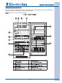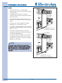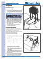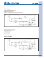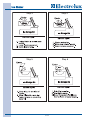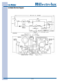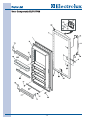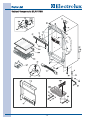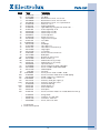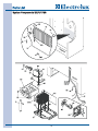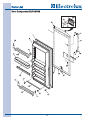
1
Technical Service Manual
Upright Freezer
EILFU17GS & EILFU21GS
FREEZER SERVICE MANUAL #5995516548
2008 ALL RIGHTS RESERVED
Basic Information
Section 1
Basic Information
1-1
Basic Information
Section 1 - Basic Information ................................
1-1
Table of Contents....................................................
Safe Servicing Practices ........................................
Features ..................................................................
Serial Number Breakdown......................................
EILFU17GS0 ..........................................................
EILFU21GS0 ..........................................................
1-2
1-3
1-4
1-4
1-5
1-6
Section 2 - Installation Information ........................
2-1
Important Safety Instructions ................................
Safety Precautions..................................................
Location ..................................................................
Electrical Information ..............................................
Leveling ..................................................................
Door Removal ........................................................
Water Supply ..........................................................
Unit Dimensions......................................................
2-2
2-2
2-4
2-5
2-6
2-6
2-7
2-8
Section 3 - Electronic Control ................................
3-1
Electronic Temperature Control ..............................
Setting Freezer Control ..........................................
Alarm Function Table ..............................................
Normal Operation ..................................................
Temperature Display ............................................
Temperature Scale................................................
Fast Freeze ..........................................................
Control Lock ........................................................
Mute Sounds ........................................................
Alarms ....................................................................
Temperature Alarm ..............................................
Power Fail Alarm ..................................................
Door Ajar ..............................................................
Communication Error ..........................................
Thermistor Error....................................................
Stuck Key Error ....................................................
Fail Safe Mode......................................................
Defrost Mode ..........................................................
Defrost Timing ........................................................
Manual Defrost ......................................................
Showroom Mode ....................................................
Test Mode ..............................................................
Service Diagnostic Mode........................................
Initiate Service Mode............................................
Model Identification ..............................................
Software Version ..................................................
Door Switch Status ..............................................
Thermistor Status ................................................
Reset Factory Defaults ........................................
Exit Diagnostics Mode..........................................
3-2
3-2
3-2
3-3
3-3
3-3
3-3
3-3
3-3
3-4
3-4
3-4
3-4
3-4
3-4
3-4
3-4
3-5
3-5
3-5
3-5
3-5
3-6
3-6
3-6
3-6
3-6
3-6
3-6
3-6
Section 4- Refrigeration System ............................
4-1
Definitions ..............................................................
Safety Warnings......................................................
Charging Sealed Systems ......................................
Soldering ................................................................
Basic Components ................................................
Perimeter Hot Tube ................................................
Refrigerant Cycle ....................................................
4-2
4-2
4-2
4-3
4-3
4-3
4-3
1-2
Low/High Side Leak or Undercharge ....................
Testing for Refrigerant Leaks..................................
Compressor Replacement ......................................
To Flush the System ..............................................
To Use Dry Nitrogen to Flush the System ..............
To Use Refrigerant to Flush the System ................
Installing a New Compressor ................................
Condenser Replacement ........................................
Filter-Drier Replacement ........................................
Evaporator and Suction Line Replacement............
Equipment Needed for Evacuation & Recharging..
Installing Evacuation and Recharging Equipment..
Evacuating System ................................................
Charging the System ..............................................
Preparing the Charging Cylinder ............................
Final Leak Test ........................................................
Verify Refrigerant Type in the System ....................
Dedicated Equipment ............................................
R-134a Refrigeration Systems................................
Miscibility of R-134a and Ester Oil ........................
Water in the Refrigeration System..........................
Vacuum Pump Maintenance ..................................
Refrigerant Leaks....................................................
Leak Detection........................................................
R-134a Properties ..................................................
HFC-134a, CFC-12 Pressure Temp. Chart ............
Inhalation Toxicity ..................................................
Cardiac Sensitization ..............................................
Spills or Leaks ........................................................
Skin and Eye Contact ............................................
Combustibility of HFC-134a ..................................
Leak Testing............................................................
Bulk Delivery and Storage ......................................
Filling and Charging Operations ............................
Refrigerant Recovery Systems ..............................
Thermal Decomposition..........................................
4-4
4-4
4-4
4-5
4-5
4-5
4-6
4-7
4-8
4-8
4-9
4-9
4-10
4-10
4-10
4-11
4-12
4-12
4-12
4-12
4-13
4-14
4-14
4-15
4-15
4-16
4-17
4-17
4-17
4-17
4-18
4-18
4-18
4-18
4-18
4-18
Section 5- Component Teardown ..........................
5-1
Warnings and Cautions ..........................................
Exterior Components..............................................
Door Handle ........................................................
Kickplate ..............................................................
Door Hinge and Door Assembly ..........................
Lower Hinge Assembly ........................................
Door Gasket and Inner Panel ..............................
Door Lock ............................................................
Control Panel ........................................................
Tilt-Out Wire Shelf ................................................
Door Shelf Guard..................................................
Door Switch ..........................................................
Interior Components ..............................................
Upper Shelf Assembly..........................................
Wire Basket ..........................................................
Wire Basket Slide ................................................
Light Shield ..........................................................
Light Fixture..........................................................
5-2
5-3
5-3
5-3
5-3
5-4
5-4
5-5
5-5
5-5
5-6
5-6
5-6
5-6
5-7
5-7
5-7
5-7
Basic Information
Baffle Plate ..........................................................
Icemaker ..............................................................
Evaporator Cover ................................................
Evaporator Fan Assembly ....................................
Defrost Thermostat ..............................................
Thermistor ............................................................
Defrost Heater ......................................................
Evaporator ..........................................................
Compressor Area....................................................
Power Cord ............................................................
Water Valve ............................................................
Filter-Drier ..............................................................
Compressor ............................................................
Drain Pan ................................................................
Condenser Fan Motor ............................................
Condenser ..............................................................
Control Module ......................................................
5-8
5-8
5-8
5-9
5-9
5-9
5-10
5-10
5-11
5-11
5-11
5-12
5-13
5-14
5-14
5-15
5-15
Section 6- Icemaker ..............................................
6-1
Safe Servicing Practices
Avoid personal injury and/or property damage by
observing important Safe Servicing Practices.
Following are some limited examples of safe
practices:
1. DO NOT attempt a product repair if you have
any doubts as to your ability to complete the
repair in a safe and satisfactory manner.
2. Always Use The Correct Replacement Parts as
indicated in the parts documentation.
Substitutions may defeat compliance with
Safety Standards Set For Home Appliances.
Do not exceed maximum recommended
wattage on light bulb replacements. Doing so
could blow fuses and/or damage transformers.
3. Before servicing or moving an appliance:
• Remove power cord from the electrical outlet,
trip circuit breaker to the OFF position, or
remove fuse.
• Turn off water supply.
4. Never interfere with the proper operation of any
safety device.
5. Use ONLY REPLACEMENT PARTS
CATALOGED FOR THIS APPLIANCE.
Substitutions may defeat compliance with
Safety Standards Set For Home Appliances.
6. GROUNDING: The standard color coding for
safety ground wires is GREEN, or GREEN with
YELLOW STRIPES. Ground leads are not to be
used as current carrying conductors. It is
EXTREMELY important that the service
technician reestablish all safety grounds prior
to completion of service. Failure to do so will
create a hazard.
7. Prior to returning the product to service, ensure
that:
• All electrical connections are correct and
secure.
• All electrical leads are properly dressed and
secured away from sharp edges, hightemperature components, and moving parts.
• All non-insulated electrical terminals,
connectors, heaters, etc. are adequately
spaced away from all metal parts and panels.
• All safety grounds (both internal and external)
are correctly and securely connected.
• All panels are properly and securely
reassembled
Rear Mounted Icemaker ........................................ 6-2
Icemaker Components .......................................... 6-3
Front Cover ............................................................ 6-3
Ice Mold .................................................................. 6-3
Mold Heater ............................................................ 6-3
Ice Stripper ............................................................ 6-3
Water Valve Assembly ............................................ 6-3
Thermostat.............................................................. 6-3
Sensing Arm and Linkage ...................................... 6-3
Timing Switches .................................................... 6-4
Thermal Cut-Out (TCO) .......................................... 6-4
Timing Cam and Coupler........................................ 6-4
Timing Gear ............................................................ 6-4
Motor ...................................................................... 6-4
On/Off Switch ........................................................ 6-4
Wiring...................................................................... 6-4
Installing Water Supply Line to Icemaker .............. 6-5
Water Valve Switch- Water Fill Volume .................. 6-5
Test Cycling Icemaker ............................................ 6-5
Operating Cycle Illustrations-Manual Cycle .......... 6-6
Operating Cycle Illustrations-Electrical .................. 6-6
Operating Cycle Illustrations-Mechanical .............. 6-13
Ice Maker Electrical Diagram.................................. 6-16
Section 7- Parts List and Exploded Views ............
7-1
Door Components EILFU17GS .............................. 7-2
Cabinet Components EILFU17GS.......................... 7-4
System Components EILFU17GS .......................... 7-6
Door Components EILFU21GS .............................. 7-8
Cabinet Components EILFU21GS.......................... 7-10
System Components EILFU21GS .......................... 7-12
Ice Maker Components ........................................ 7-14
Section 8- Troubleshooting ....................................
8-1
Troubleshooting Chart ............................................
8-2
Section 9- Wiring Diagrams ....................................
9-1
Wiring Diagram ......................................................
9-2
1-3
Basic Information
Features
21 Cu. Ft. Upright Freezer
EILFU21G S
17 Cu. Ft. Upright Freezer
EILFU17G S
Yes
Yes
Total Volume
20.6 Cu. Ft.
16.8 Cu. Ft.
Shelf Area
23.2 Sq. Ft.
20 Sq. Ft.
IQ Touch Electronic Control
Yes
Yes
Digital Exterior Control Center
Yes
Yes
Frost-Free Performance
Yes
Yes
Adjustable Temperature Control
Yes
Yes
Display Temperature Mode
Yes
Yes
Fast Freeze
Yes
Yes
High Temperature Alarm System
Yes
Yes
System Error Alarm
Yes
Yes
Interior Lighting
Yes
Yes
Power On Light
Yes
Yes
Adjustable Glass Shelves
2
2
Fixed Glass Shelves
2
2
Full Access Baskets
3
2
Adjustable Door Bins
2
2
Contour Door Shelves
1
1
Tilt Out Wire Door Shelves
3
2
Automatic Icemaker
Yes
Yes
Lock With Pop Out Key
Yes
Yes
Automatic Door Closer
Yes
Yes
Right Bottom Rear
Right Bottom Rear
Left Bottom Rear
Left Bottom Rear
115V/60Hz/15A
115V/60Hz/15A
Connected Load @ 115V
.69
.62
Minimum Circuit Required Amps
15
15
Product Weight
251 Lbs
225 Lbs
Shipping Weight (Approx.)
269 Lbs
240 Lbs
Energy Star
Specifications
Power Supply Connection
Water Inlet Location
Voltage Rating
Serial Number Breakdown
The serial plate is located on the left side wall of
the freezer interior.
1-4
Basic Information
Understanding Features And Terms
Electrolux freezers are designed for optimal convenience and storage flexibility. Use the illustration below
to familiarize yourself with product features and terminology.
NOTE: Features may vary according to model.
17 CU. FT. MODEL SHOWN
1-5
Basic Information
Understanding Features And Terms
Electrolux freezers are designed for optimal convenience and storage flexibility. Use the illustration below
to familiarize yourself with product features and terminology.
NOTE: Features may vary according to model.
21 CU. FT. MODEL SHOWN
1-6
Installation Information
Section 2
Installation Information
2-1
Installation Information
IMPORTANT SAFETY INSTRUCTIONS
Safety Precautions
Do not attempt to install or operate this appliance until you read the safety precautions in this guide.
Safety items throughout this guide are labeled with a Warning or Caution based on the risk type.
WARNING indicates a potentially hazardous situation which, if not avoided, could result in death or
serious injury.
Caution indicates a potentially hazardous situation which, if not avoided, may result in minor or
moderate injury.
WARNING
ELECTROLUX CANNOT BE HELD RESPONSIBLE FOR DAMAGE TO PROPERTY OR INJURY TO
PERSONS CAUSED BY FAILURE TO COMPLY WITH THE INSTALLATION, MAINTENANCE AND
SAFETY INSTRUCTIONS CONTAINED IN THIS SERVICE MANUAL.
WARNING
TO REDUCE THE RISK OF FIRE, ELECTRICAL SHOCK, OR INJURY WHEN USING YOUR FREEZER,
FOLLOW BASIC SAFETY PRECAUTIONS INCLUDING THE FOLLOWING:
-
READ ALL INSTRUCTIONS BEFORE OPERATING THE FREEZER.
-
BEFORE PERFORMING ANY TYPE OF SERVICE OR INSTALLATION, MAKE SURE THAT
ELECTRIC P O W E R T O T H E F R E E Z E R I S D I S C O N N E C T E D .
-
TO AVOID THE POSSIBILITY OF EXPLOSION OR FIRE, DO NOT STORE OR USE COMBUSTIBLE,
FLAMMABLE, OR EXPLOSIVE LIQUIDS OR VAPORS (SUCH AS GASOLINE) INSIDE OR IN THE
VICINITY OF THIS OR ANY OTHER APPLIANCE.
-
THIS APPLIANCE IS EQUIPPED WITH A THREE-PRONG GROUNDING PLUG FOR PROTECTION
AGAINST POSSIBLE ELECTRIC SHOCK HAZARDS. PLUG IT ONLY INTO A DEDICATED,
GROUNDED ELECTRICAL OUTLET. WHEN ONLY A STANDARD TWO-PRONG ELECTRICAL
OUTLET IS AVAILABLE, THE CUSTOMER MUST HAVE IT REPLACED WITH A DEDICATED,
PROPERLY GROUNDED THREE-PRONG ELECTRICAL OUTLET BEFORE USING THIS
APPLIANCE. DO NOT UNDER ANY CIRCUMSTANCES, CUT OR REMOVE THE THIRD (GROUND)
PRONG FROM THE POWER CORD. DO NOT USE AN ADAPTER PLUG. DO NOT USE AN
EXTENSION CORD. DO NOT USE A POWER CORD THAT IS FRAYED OR DAMAGED. THE USE
OF A GROUND FAULT INTERRUPTER (GFI) IS NOT RECOMMENDED.
-
DO NOT INSTALL OR USE A DAMAGED APPLIANCE. IF YOU RECEIVE A DAMAGED
APPLIANCE, IMMEDIATELY CONTACT YOUR DEALER OR BUILDER.
-
DO NOT USE THE FREEZER UNTIL IT HAS BEEN PROPERLY INSTALLED BY A QUALIFIED
INSTALLER ACCORDING TO THESE INSTALLATION INSTRUCTIONS. THE INSTALLER MUST
SHOW THE CUSTOMER THE LOCATION OF THE POWER PLUG SO THAT THEY KNOW WHERE
AND HOW TO DISCONNECT POWER TO THE FREEZER.
-
DO NOT INSTALL, REPAIR, OR REPLACE ANY PART OF THE FREEZER UNLESS
SPECIFICALLY RECOMMENDED IN THE LITERATURE ACCOMPANYING IT. A QUALIFIED
SERVICE TECHNICIAN SHOULD PERFORM ALL OTHER SERVICE.
2-2
Installation Information
WARNING
DESTROY CARTON, PLASTIC BAGS, AND ANY EXTERIOR WRAPPING MATERIAL IMMEDIATELY
AFTER THE FREEZER IS UNPACKED. CHILDREN SHOULD NEVER USE THESE ITEMS FOR PLAY.
CARTONS COVERED WITH RUGS, BEDSPREADS, PLASTIC SHEETS OR STRETCH WRAP MAY
BECOME AIR TIGHT CHAMBERS AND CAN QUICKLY CAUSE SUFFOCATION.
A CHILD MIGHT SUFFOCATE IF HE CRAWLS INTO THE FREEZER TO HIDE OR PLAY. REMOVE
THE DOOR/LID OF THE FREEZER WHEN NOT IN USE, EVEN IF YOU PLAN TO DISCARD THE
FREEZER. MANY COMMUNITIES HAVE LAWS REQUIRING YOU TO TAKE THIS SAFETY
PRECAUTION.
REMOVE OR DISCARD ANY SPACERS USED TO SECURE THE SHELVES DURING SHIPPING.
SMALL OBJECTS ARE A CHOKE HAZARD TO CHILDREN.
CHILD ENTRAPMENT AND SUFFOCATION ARE NOT PROBLEMS OF THE PAST. JUNKED OR
ABANDONED REFRIGERATORS OR FREEZERS ARE STILL DANGEROUS– EVEN IF THEY WILL SIT
FOR “JUST A FEW DAYS”. IF YOU ARE GETTING RID OF YOUR OLD REFRIGERATOR OR
FREEZER, PLEASE FOLLOW THE INSTRUCTIONS BELOW TO HELP PREVENT ACCIDENTS:
•REMOVE THE DOOR/LID.
•LEAVE SHELVES IN PLACE SO CHILDREN MAY NOT EASILY CLIMB INSIDE.
•HAVE THE REFRIGERANT REMOVED BY A QUALIFIED TECHNICIAN.
2-3
Installation Information
Location
1”Air Space
1. Choose a place that is near a grounded
electrical outlet. Do Not use an extension cord or
an adapter plug.
2. If possible, place the freezer out of direct
sunlight and away from the range, dishwasher or
other heat sources.
1”
3. The freezer must be installed on a floor that is
level and strong enough to support a fully loaded
freezer.
3/8”
4. Consider water supply availability for models
equipped with an automatic ice maker.
3/8”
5. The freezer should be located where surrounding
temperature will not exceed 110ºF (43ºC) or drop
below 40°F (5°C)
Installation for 17 cu. ft.
with dynamic condenser
6. For ease of installation, proper air circulation
and electrical connections, refer to the illustration
for recommended clearances.
3”Air Space
7. For dynamic condenser models, DO NOT block
the toe grille on the lower front of your freezer.
Sufficient air circulation is essential for the proper
operation of your freezer.
3”
NOTE
The exterior walls of the freezer may become
quite warm as the compressor works to transfer
heat from the inside. Temperatures as much as
30°F warmer than room temperatures can be
expected.
3”
3”
1”
Installation for 21 cu. ft.
without dynamic condenser
2-4
Installation Information
Electrical Information
These guidelines must be followed to ensure that
safety mechanisms in the design of this freezer will
operate properly.
Refer to the serial plate for correct electrical rating.
The power cord of the freezer is equipped with at
three-prong grounding plug for protection against
shock hazards. It must be plugged directly in to its
own properly grounded three-prong receptacle,
protected with a 15 amp time delay fuse or circuit
breaker. The receptacle must be installed in
accordance with the local codes and ordinances.
Consult a qualified electrician. Receptacles with
Ground Fault Circuit Interrupters (GFCI) are NOT
RECOMMENDED. DO NOT USE AN EXTENSION
CORD OR AN ADAPTER PLUG.
If the voltage varies by 10 percent or more, freezer
performance may be affected. Operating the freezer
with insufficient power can damage the motor. Such
damage is not covered under the warranty. If you
suspect your voltage is high or low, consult your
power company for testing.
To prevent the freezer from being turned off
accidentally, do not plug the unit in to an outlet
controlled by a wall switch or pull cord.
Do not pinch, knot, or bend the power cord in any
manner.
WARNING
NEVER UNPLUG THE FREEZER BY PULLING
ON THE POWER CORD. ALWAYS GRIP THE
PLUG FIRMLY AND PULL STRAIGHT OUT
FROM THE RECEPTACLE.
TURNING THE CONTROL TO “OFF” TURNS
OFF THE COMPRESSOR BUT DOES NOT
DISCONNECT POWER TO OTHER ELECTRICAL
COMPONENTS.
2-5
Installation Information
Leveling
Turn
Left To
Raise
The freezer must have all bottom corners resting
firmly on a solid floor. The floor must be strong
enough to support a fully loaded freezer. It is VERY
IMPORTANT for your freezer to be level in order to
function properly. If the freezer is not leveled during
installation,the door/lid may be misaligned and not
close or seal properly, causing cooling, frost or
moisture problems.
Turn
Right To
Lower
Plastic
Leveling F eet
Crating
Screw
To Level Unit
After discarding crating screws and wood base, use
a carpenter’s level to level the freezer from front to
back. Adjust the plastic leveling feet in front, ½
bubble higher, so that the door closes easily when
left half way open.
Door Removal
Discard The (4) Crating
Screws And Wood Base
For some installations it may be necessary to remove
the door to fit through the entrance of the installation
site.
To remove the door, follow the steps below.
1. Make sure electrical plug is disconnected from
the wall outlet.
2. Gently lay freezer on its back on a soft clean
surface.
Grille/ Kickplate
3. Lift plastic cover off upper hinge assembly.
Hinge Bolt
4. Using a 3/8” open end wrench or socket, extract
screws securing the top hinge to the unit frame.
Hinge Screw
5. Remove the toe grille by grabbing the toe grille
at the top with both hands, then pull away from
the unit until toe grille disengages from the unit.
6. Reach under bottom of cabinet and disconnect
wire leads of door connector from the cabinet
connector.
Wire
Door Connector
Cabinet Connector
7. Using a 3/8” open end wrench or socket,
extract screws securing the bottom hinge to the
unit frame. Use a phillips head screwdriver to
extract the remaining screw from the bottom
hinge assembly.
8. Lift the door assembly off of the unit frame.
2-6
Water Supply
8. Coil the excess copper tubing (about 2½ turns)
Behind your freezer as shown. Arrange
coiled tubing to avoid vibration or wear against
other surfaces.
9. Open water supply shut-off valve and tighten
any connections that leak.
10. Reconnect power to freezer.
11. Turn icemaker on and lower ice level arm to start
icemaker operation.
The automatic ice maker requires a permanent water
supply to function correctly. During installation,
establish this water supply by connecting a copper
tube from the household water system to a valve at
the rear of the freezer.
What you will need:
•
•
•
•
Access to a cold water line with pressure of 20120 psi. (System supplied with cold water only.)
Copper tubing with ¼inch (6.4mm) Outside
Diameter (OD). Length for this tubing is the
distance from the rear of the freezer to your
house hold water supply line plus seven feet
(2.1 meters).
A shut-off valve for the connection between the
household water line and the freezer supply line.
Do not use a self-piercing shut-off valve.
A compression nut and ferrule (sleeve) for the
water supply connection at the rear of freezer.
Plastic Water Tu bing
to Ice Maker
Fill Tu be
Steel
Clamp
Brass
Compression
Nut
Ferrule
(Sleeve)
Coppe r
water line
Water Valv e
Bracke t
NOTE
Valve Inlet
Kit # 5303917950 is available from your dealer
that provides all materials for a water supply
installation, including 25 feet of copper tubing, a
saddle type shutoff valve, (2) 1/4” brass
compression nuts, (2) ferrules/sleeves and full
instructions.
Water Valve
Copper water line
from household water supply
(Include enough tubing in loop
to allow moving freezer out
for cleaning)
To connect the water supply to the rear of the
freezer:
1. Ensure that the freezer is not plugged in.
2. Flush the supply line until water is clear by
placing the end of the copper tube in a sink or
bucket and opening the shut-off valve. Then turn
off water supply at valve.
3. Unscrew the plastic cap from the water valve
inlet at the rear of the freezer. Discard the cap.
4. Slide the brass compression nut, then the ferrule
(sleeve) onto copper tube.
5. Push the copper tube into water valve inlet as far
as it will go (¼ inch).
6. Slide the ferrule (sleeve) into valve and finger
tighten the compression nut onto valve. Tighten
another half turn with a wrench. Do not
over-tighten.
7. Secure the copper tube to your freezer’s rear
panel with a steel clamp and screw (See
Illustration).
2-7
Unit Dimensions
Overall depth at center
of arc 29-½”
28 ½”
Overall depth at center
of arc 27-½”
26½”
32”
CL
32”
CL
70- 5∕8” min.
71- 5∕8” max.
65-½” min.
66-½” max.
Water line
inlet location
(left bottom rear)
Water line
inlet location
(left bottom rear)
Power cord
location
(right bottom rear)
Power cord
location
(right bottom rear)
26 -¼”
24-¼”
31-¼”
29-¼”
59
(with doors 90˚ open)
Note:
To allow for proper airflow,
3”minumum surrounding
airspace required on each
side, with 1” at back and top
with 1” at bottom.
(with doors 90˚ open)
EILFU21G S
Unit Dimensions
Note:
To allow for proper airflow,
minumum surrounding
airspace required on each
side, with 1” at back and top.
EILFU17G S
Unit Dimensions
2-8
Electronic Control
Section 3
Electronic Control
3-1
Electronic Control
Electronic Temperature Control
The electronic temperature control is located on the freezer door. Temperature is factory preset to provide
satisfactory food storage temperatures. Refer to the SETTING FREEZER CONTROL Quick Reference Guide
below for more details.
SETTING FREEZER CONTROL
Press and
hold for 3
seconds to
toggle F or C
in the display.
Turns the
temperature
display ON or
OFF.
Press to
mute
audible
alarms.
Press to turn the
sounds ON or OFF.
When the LED is ON,
the sounds are muted.
Press and hold
for 3 seconds to
start or cancel
control lock.
Press to start or
cancel the fast
freeze feature.
Press to
increase the
temperature
setting
Press to
decrease the
temperature
setting
Indicates the
door has been
open 5 minutes
or more.
Indicates the
temperature was
above +23°F ( -9°C)
for at least one
hour.
Indicates the
power was
interrupted.
ALARM FUNCTION TABLE
Display
Priority
“HI”
3
Alternating “E1”
and temperature
2
Visual Alarm
Alarm Status
“HI Temp” LED ON and
mute sounds LED flashes
mute sounds LED flashes; 1
second set temperature, 1
second “E1”
Freezer temperature
over the safe limit
Fail Safe Mode
Communication Error
Alternating “CE”
and temperature
1
mute sounds LED flashes; 1
second set temperature, 1
second “CE”
Alternating “E2”
and temperature
4
Actual
Temperature
6
Set Temperature
5
mute sounds LED flashes; 1 Stuck Key Error
second set temperature, 1
second “E2”
power fail LED on and mute Cabinet greater than 10
degrees over the SET
sounds LED flashes
TEMP. at power up.
Door open for more than
door ajar LED on and mute
5 minutes
sounds LED flashes
Action(s) Required
Press the mute sounds key
to stop the audible alarm
Check thermistor status
Press the mute sounds key
to stop the audible alarm
Check connection between
UI and ECU. Press the mute
sounds key to stop the
audible alarm
Check membrane keys.
Press the mute sounds key
to stop the audible alarm
Press the mute sounds key
to stop the audible alarm
Press the mute sounds key
to stop the audible alarm
NOTE: The unit can reach as low as -35 degrees during the Fast Freeze Mode but ideally the mode is for
initial startup and the addition of product during restock.
NOTE: Standard Ice Maker Production; 3.5-4 lbs/24hrs.
NOTE: A more in depth description of the alarms is given on page 3-4.
3-2
Electronic Control
Normal Operation
+) key to
The user can select any temperature setting from -10°F to 10°F (-24°C to -12°C). Press the plus (+
increment or the minus (-- ) key to decrement the temperature setting by one degree each key press. If a key
is not pressed within 3 seconds, the confirmation tone sounds and the set temperature blinks once before
changing to the new temperature setting. The display turns off 10 seconds later.
If the temperature display is OFF, the first press of + or - key displays the current temperature setting. Then
pressing the + or - will change the current setting. If the temperature display is ON, the first press of the + or will change the current setting by one degree.
The OFF setting is the position past the 10°F setting. A confirmation tone is sounded when switching to OFF
position. In the OFF position, all functions (compressor, defrost, and alarms) will be disabled except the light
control. When a temperature alarm condition is present and the set temperature is changed to the OFF
setting, the visual and audible alarms end.
Temperature Display
Press the temp display key to toggle temperature display ON or OFF. The default setting is OFF.
The acceptance tone sounds when the option is changed. The "FREEZER TEMP" LED on the display is
always ON.
Temperature Scale
Press and hold the temp display key for 3 seconds to switch between degrees F and degrees C. The
confirmation tone sounds after the 3 seconds. Initial default setting is Fahrenheit. Temperature displayed is
rounded to the nearest whole number.
If the temperature display is OFF, the display turns on and displays the set temperature and the change in
temperature scale. The display returns to OFF state after 3 seconds. If the temperature display is ON, the
temperature scale change is visible.
Fast Freeze
Engagement of the fast freeze function turns the compressor on for 72 hours. The fast freeze LED is enabled
when fast freeze is engaged and the acceptance tone sounds. The fast freeze key toggles the state ON or
OFF. The set temperature is displayed if temp display state is ON. The user is allowed to change the set
temperature while in fast freeze mode. The new set temperature will be used when the fast freeze cycle is
complete. Defrost will function normally during fast freeze. Fast freeze will not engage if the temperature
setting is "OFF". If fast freeze is activated during defrost, the LED will turn on but the compressor will not
come on until after the defrost cycle is completed. The freezer returns to the previous temperature setting
after the 72 hours. Manual defrost is not available while in fast freeze mode.
Control Lock
Press and hold the control lock key for three seconds to activate or deactivate the freezer control lockout
feature which prevents user key entries. After the three seconds, the confirmation tone sounds and the
control lock LED will be displayed indicating that the control is locked. If a key is pressed while locked, the
control lock LED will flash twice and the invalid tone will sound. If an alarm occurs while in the locked mode,
the mute sounds key will be enabled to mute the alarm. When the lockout is deactivated, the control lock
LED will turn off.
Mute Sounds
The mute sounds key will enable or disable the audible sounds, i.e. key acceptance and confirmation tones.
The default state is mute sounds OFF and the corresponding LED is OFF. When you press mute sounds to
enable mute feature, the acceptance key tone does not sound. When you press mute sounds to disable mute
option, the acceptance key tone does sound. When you turn ON the mute sounds, the mute sounds LED
turns ON and all tones except alarms are eliminated. When the tones have been muted, the audible alarms
will still operate normally. The mute sounds key is also used for muting audible alarms.
3-3
Electronic Control
Alarms
Temperature Alarm
If the temperature of the cabinet remains above alarm activation temperature of 23.0°F +/- 3 F° (-5°C +/- 2°C)
for more than 1 hour, the high temp LED will turn ON, mute sounds LED will flash, the display will show "HI",
and the buzzer sounds the alarm tones. "HI" will continue to be displayed until the mute sounds key is
pressed even if cabinet temperature decreases. The highest temperature will display for 10-seconds. Next,
the freezer will display the set temperature if cabinet temperature is not above the upper control limit. If the
cabinet temperature is above the upper control limit, the actual cabinet temperature will be displayed until the
set temperature is reached. The display will not turn off until the temperature is below the alarm temperature.
Power Fail Alarm
The red power fail LED will illuminate when the microprocessor initiates and the cabinet temperature is greater
than 10°F over the set temperature. The current temperature will be displayed and blinking. To acknowledge
the alarm, press the mute sounds key. The audible alarm and power fail LED will then turn OFF. If the temp
display is OFF, the display will turn OFF 10 seconds after the alarm is cleared.
Door Ajar Alarm
When the door is left open for 5 or more minutes, the alarm sounds. The door ajar LED turns ON. The
display will not change. Close the door or press the mute sounds key to turn the audible alarm off. The door
ajar LED remains on until the door is closed.
Communication Error
If a communication error occurs, the freezer will operate in "Fail Safe Mode". The display will alternate
between "CE" and set temperature in 1 second intervals. The mute sounds LED flashes. Check connection
between UI & ECU. Press the mute sounds key to stop the audible alarm. No features will activate during a
communication error because the error will prevent proper operation.
Thermistor Error
If a thermistor error occurs, the freezer will operate in "Fail Safe Mode". The display will alternate between
"E1" and set temperature in 1 second intervals. The mute sounds LED flashes. Check the thermistor status.
Press the mute sounds key to stop the audible alarm.
Stuck Key Error
If a key is stuck, the freezer will maintain the current set temperature. The display will alternate between "E2"
and set temperature in 1 second intervals. The mute sounds LED flashes. Check membrane keys. Try
pressing mute sounds key to stop the audible alarm. The audible indication times out in 30 seconds.
Fail Safe Mode
When the unit goes into Fail Safe mode for a communications or thermistor error, the compressor will run
continuously.
3-4
Electronic Control
Defrost Mode
All models have an automatic defrost mode. Defrost will not engage if the control is in "OFF" position. When
defrost is manually initiated or terminated, an audible confirmation beep will occur.
Defrost Timing
After each 12 hours of accumulated compressor run time, a 30 minute defrost cycle is automatically engaged.
Before initiating the defrost cycle, the compressor is turned off. The freezer will exit defrost mode after 30
minutes and start cooling to maintain the previous control setting.
Manual Defrost
Changing defrost states has precedence over normal run mode. Defrost can be toggled ON or OFF. Each
time defrost mode is changed, it will reset the compressor run time. Defrost state can be changed by
pressing and holding both fast freeze and mute sounds keys simultaneously for 3 or more seconds.
The confirmation tone will sound to confirm that the state has changed and "dEF" will display for 3 seconds.
If the display is OFF, display returns to OFF state after 3 seconds. The user is allowed to change the set
temperature while in manual defrost. The new set temperature will be used when the defrost cycle is
complete. Diagnostic mode is not available while in manual defrost.
Showroom Mode
Showroom mode allows a sales person to demonstrate the freezer features without turning the compressor on
or going through defrost cycles. Set the control to OFF position. Press and hold the + and - keys for 3
seconds to initiate show room mode. The display will show "SS" displaying for 3 seconds and the
confirmation tone will sound. All keys should operate normally during showroom mode. The cabinet light will
operate during showroom mode but the compressor and defrost heater will remain OFF. Set the control to
OFF and press and hold the + and - key for 3 seconds to end the showroom mode. No alarms will occur
during showroom mode. The showroom mode is automatically exited after a power failure.
Test Mode
To initiate "Test Mode" the J4 pins should be shorted before power up. All LED segments will illuminate for the
duration of 2 seconds. Each key that is pressed on the control will cause an LED to illuminate and stay
illuminated while in this mode. A numeric segment will be illuminated in each display with each key press. To
test communication, TX would need to be connected to RX. Remove power to exit the test mode.
Press
Press
Press
Press
Press
Press
the
the
the
the
the
the
fast freeze key to illuminate the fast freeze LED.
temp display key to illuminate the high temp LED.
mute sounds key to illuminate the mute sounds LED.
control lock key to illuminate the control lock LED.
(minus) "--" key to illuminate the door ajar LED.
+" key to illuminate the power fail LED.
(plus) "+
ECU
Programming
Header
Neutral Input
UI
Light Out
Heater Out
5V Power
Comp. Out
Line Input L1
Thermistor
Ground
TX
RX
RX
TX
Door Switch
Keypad
3-5
Electronic Control
Service Diagnostic Mode
Initiate Service Mode
The service technician should set the temperature to 0 F, then press and hold both the + and - keys
simultaneously for 3 seconds.
When the diagnostics mode is entered, the number "88" is displayed and the confirmation tone is sounded.
The status information will be displayed for 3 seconds and then return to the diagnostics indicator.
Model Identification
+) key to display the model number.
Press the plus (+
Once you have displayed the model ID, press and hold
+) and fast freeze keys for 3 or more seconds
the plus (+
to select the option to change the model ID. The model
ID will increment or decrement by pressing the + or key. The model ID can be saved immediately by
pressing mute sounds key.
Software Version
Press the fast freeze key to display the production software version for the model. (The limitation is 00 - 99
production software versions per model.) The minus and 2 digit version number "-xx" is displayed.
Door Switch Status
Press the "--" key to display the door switch status.
dO" is displayed.
If the door switch is open, the letter "d
dC" is displayed.
If the door switch is closed, the letter "d
Thermistor Status
Press the mute sounds key to display the thermistor status.
If the thermistor is operating properly, the characters "-- -" are displayed.
If the thermistor is open, the letter "ttO" is displayed.
If the thermistor is shorted, the letter "ttS" is displayed.
The thermistor status is not updated in showroom mode. The characters "-- -" are always displayed
Reset Factory Defaults
Press the fast freeze key while the software version is displayed to reset all EEPROM values to the factory
defaults. The model ID will not be affected. The user interface will exit diagnostics mode and automatically
restart in normal power up operation.
Exit Diagnostic Mode
To exit service mode, the service technician should press and hold both the + and - keys simultaneously for 3
or more seconds. The buzzer beeps at the end of 3 seconds.
3-6
Refrigeration System
Section 4
Refrigeration System
4-1
Refrigeration System
Safety Warnings
NOTE
Instructions given here are furnished as a
guide. P e r s o n s a t t e m p t i n g t o u s e t h e s e
instructions to make repairs to the sealed
refrigeration system should have a working
knowledge of refrigeration and previous training
on sealed system repair, and an EPA certifica tion for servicing refrigeration systems.
IMPORTANT
Effective July 1, 1992, the United States clean
air act governs the disposal of refrigerants such
as R-134a. Therefore, when discharging or
purging the sealed system use an EPA approved
refrigerant recovery system as outlined in the
final rule on the protection of stratospheric
ozone and refrigerant recycling, which was
published in the Federal Register May 14, 1993.
NOTE
Electrolux does not permit the use of recovered
refrigerant in the servicing of our products for
in-warranty and out-of-warranty repairs or for
products covered by service contracts.
Therefore, only new refrigerant or refrigerant that
has been reclaimed back to new specifications
by a refrigerant manufacturer is to be used.
Definitions
Recovery:
To remove refrigerant in any condition from a
system and store it in an external container without
necessarily testing or processing it in any way.
Recycling:
To clean refrigerant for reuse by oil separation and
single or multiple passes through devices, such as
replaceable core filter-driers, which reduce
moisture, acidity and particulate matter. This term
usually applies to procedures implemented at the
field job site or at a local service shop.
Compressor Testing
Whenever testing a compressor, extreme caution
should be used to prevent damaging the terminals.
A compressor with a damaged terminal or a
grounded winding can expel a terminal from its
insulated housing when the compressor is
energized. If this happens, a mixture of refrigerant
and oil will be released that could be ignited by an
external heat source (open flame, heater, etc.).
Also, if there is air in the system when this
happens, a spark at the compressor shell could
ignite the refrigerant and oil mixture.
Charging Sealed Systems
Overcharging a refrigeration system with refrigerant
can be dangerous. If the overcharge is sufficient
to immerse the major parts of the motor and
compressor in liquid refrigerant, a situation has
been created which, when followed by a sequence
of circumstances can lead to the compressor shell
seam separating.
A hydraulic block occurs, preventing the
compressor from starting. This condition is known
as locked rotor. Electric current continues to flow
through the compressor motor windings which
become, in effect, electric resistance heaters.
The heat produced begins to vaporize the excess
refrigerant liquid causing a rapid increase in
system pressure. If the compressor protective
devices fail, the pressure within the system may
rise to extremes far in excess of the design limits.
Under these conditions, the weld seam around the
compressor shell can separate with explosive
force, spewing oil and refrigerant vapor which
could ignite.
To eliminate this exceedingly rare but potential
hazard, never add refrigerant to a sealed system.
If refrigerant is required, evacuate the existing
charge and recharge with the correct measured
amount of the refrigerant specified for the system.
Reclaim:
To reprocess refrigerant to new product
specifications by means which may include
distillation, will require chemical analysis of the
refrigerant to determine that appropriate product
specifications are met. This term usually implies
the use of processes or procedures available only
at a reprocessing or manufacturing facility.
4-2
Refrigeration System
Perimeter Hot Tube
WARNING
To reduce the possibility of condensation forming
on the exterior of the cabinet in high humidity
areas, a perimeter hot tube (refrigerant tube) has
been installed in the unit. The perimeter tube
extends up the left side,across the top of the
freezer and down the right side into the filter drier.
When the compressor operates, warm refrigerant
flows through the primary condenser, then into the
primary hot tube, warming the cabinet front
exterior.
WEAR APPROVED SAFETY GLASSES WHEN
WORKING WITH OR ON ANY PRESSURIZED
SYSTEM OR EQUIPMENT. HAVE AN
APPROVED DRY TYPE FIRE EXTINGUISHER
HANDY WHEN USING ANY TYPE OF GAS
OPERATED TORCH.
1. All joints to be soldered must have proper fit.
Clearance between tubes to be soldered
should be from .001” to .006”. It is not
practical to actually measure this; however,
you do not want a dry fit or loose fit. Tubing
joints should overlap about the distance of
their diameter except for restrictor tubes,
which should be inserted 1.25”.
2. Clean all joint areas with fine steel wool or
preferably an abrasive cloth, such as grit cloth
No. 23 or Scotch-Brite.
3. Apply a thin film of liquid flux recommended
for silver soldering to surfaces to be joined and
to surfaces immediately adjacent to joint.
The perimeter hot tube is not replaceable. In the
unlikely event of a leak in the hot tube, a kit is
available to bypass the hot tube in the sealed
system. An electrical heater wire must be installed
within the tubing. Refer to the appropriate parts list
of the model being serviced for the correct kit part
number.
Refrigerant Cycle
The refrigerant cycle is a continuous cycle that
occurs whenever the compressor is in operation.
Liquid refrigerant is evaporated in the evaporator
by the heat that enters the cabinet through the
insulated walls and by the heat from product load
and door openings. The refrigerant vapor is then
drawn from the evaporator, through the suction line
to the compressor. Compression raises the
pressure and temperature of the vapor in the
compressor and the vapor is then forced through
the discharge valve into the discharge line and into
the condenser. Air passing over the condenser
surface removes heat from the high pressure vapor
which then condenses to a liquid. The liquid
refrigerant then flows from the condenser to the
evaporator through the small diameter liquid line
(capillary tube). Before it enters the evaporator, the
liquid refrigerant is sub-cooled in the heat
exchanger by the low temperature suction vapor in
the suction line. When refrigerant is added, the
frost pattern will improve, the suction and
discharge pressures will rise, the condenser will
become hot and the wattage will increase.
CAUTION
During application of heat, use wet cloths to
prevent heat from conducting to areas other
than the soldered joint. Use a sheet of metal or
torch guard pad as a heat deflector to keep
flame away from inflammable materials and
painted surfaces.
4. Align tubing so no stress is on joint. Do not
move tubing while solder is solidifying or leaks
will result.
5. Use a torch of adequate capacity so joint can
be quickly heated with a minimum of heat
travel to other points. Use a good grade of
silver solder.
6. Solder connections. If tubing is properly
cleaned and fluxed, solder will flow readily.
Use only enough solder to make a good bond.
7. Allow joint to cool, then wash exterior with
water to remove flux.
Basic Components
The basic components of a refrigerator are a
compressor, condenser, evaporator, heat
exchanger (capillary tube and suction line), drier
and perimeter hot tube.
4-3
Refrigeration System
Low/High Side Leak or Undercharge
Testing for Refrigerant Leaks
A loss of refrigerant can result in any of the
following:
1. Excessive or continuous compressor
operation.
2. Above normal freezer compartment
temperature.
3. A partially frosted evaporator (depending on
amount of refrigerant loss).
4. Below normal freezer compartment
temperature.
5. Low suction pressure (vacuum).
6. Low wattage.
The condenser will be “warm to cool”, depending
on the amount of refrigerant lost.
In the case of a low side refrigerant leak resulting
in complete loss of refrigerant, the compressor will
run but will not refrigerate. Suction pressure will
drop below atmospheric pressure and air and
moisture will be drawn into the system saturating
the filter drier.
If there is reason to believe the system has
operated for a considerable length of time with no
refrigerant and the leak occurred in the low side of
the system, excessive amounts of moisture may
have entered the system. In such cases the two
stage service Dryer Filter part number 5303918288
and vacuum procedure listed under Refrigerant
Leaks need to be followed to prevent repetitive
service.
If a slight undercharge of refrigerant is indicated
and no leak can be found after a thorough leak
test, the charge can be corrected without changing
the compressor.
If a high side leak is located and some refrigerant
remains in the system it is not necessary to
change the compressor.
NOTE
The line piercing valve (clamp-on type) should
be used for test purposes only. It must be
removed from system after it has served its
purpose.
If the system is diagnosed as short of refrigerant
and the system has not been recently opened,
there is probably a leak in the system. Adding
refrigerant without first locating and repairing the
leak or replacing the component will not
permanently correct the difficulty. The leak must be
found. Sufficient refrigerant may have escaped to
make it impossible to leak test effectively. In such
cases, add a ¼” line piercing valve to the
compressor process tube. Add sufficient
refrigerant vapor to increase the pressure to 40 to
50 lb. per sq. in. Check the low side for leaks.
Run the compressor 2 or 3 minutes and check the
high side for leaks. Recover refrigerant using an
EPA approved recovery system.
Compressor Replacement
To check for contamination, obtain oil sample from
old compressor.
1. If the oil has burned odor, but no color change
or residue — follow instructions on page 4-6
“Installing A New Compressor”.
2. If oil has a burned odor and a sugar or gritty
feel as well as showing signs of contamination
(dark color), follow instructions in next section,
To Flush The System. Remove as much of
contamination as possible from system before
installing new compressor and filter-drier.
CAUTION
NEVER install a new compressor without first
checking for possible system contamination.
NOTE
It is recommended that system be flushed with
dry Nitrogen. However, if refrigerant is used to
flush the system you must look at the serial
plate to see what type of refrigerant is used in
the system. This is the only refrigerant that can
be used to flush the system and it must be
recovered.
4-4
Refrigeration System
To Flush The System
To Use Refrigerant To Flush The System:
CAUTION
CAUTION
Use extreme care when using Dry Nitrogen to
flush systems. Pressure in nitrogen cylinder
could be as high as 2000 psi. Nitrogen cylinder
must be equipped with approved pressure
regulator and pressure relief valve. Ensure that
your hoses have adequate ratings for pressure
involved and that all of your equipment is in
good condition. The end of the flushing hose on
this tank regulator must be equipped with a
hand shut-off valve (Robinair No. 40380). Close
hand shut-off valve and adjust nitrogen regulator
to correct pressure before proceeding with
flushing procedure.
Refrigerant used for flushing must be recovered
into a recovery system. Meter amount of
refrigerant used for flushing with your charging
cylinder. DO NOT OVERFILL THE BAG.
1. Disconnect the suction and discharge lines
from the compressor and remove the
filter-drier. Connect process coupling to outlet
and inlet tube of condenser.
2. Connect hose to outlet process coupling and
charging cylinder. Connect another hose to
inlet coupling and recovery system.
3. Open charging cylinder and allow refrigerant to
flow through condenser until discharge into
bag is clear.
To Use Dry Nitrogen To Flush The System:
1. Remove compressor and filter-drier. Connect
process coupling to outlet tube of condenser.
2. Fasten cloth over other end of coil to prevent
old oil from spraying over room.
3. Connect hand shut-off valve on flushing hose
to process coupling.
4. Slowly open hand shut-off valve and allow
nitrogen to flow through condenser until
discharge is clear.
NOTE
The line piercing valve (clamp-on type) should
be used for test purposes only. It must be
removed from system after it has served its
purpose.
4. Disconnect capillary tube from evaporator.
Flush evaporator in same manner as
condenser.
5. Flush cap tube. This is only possible if you
have proper service valve adapter.
6. Reassemble system.
CAUTION
DO NOT exceed 300 PSIG.
5. Disconnect cap tube from evaporator. Flush
evaporator in same manner as condenser.
CAUTION
DO NOT exceed 150 PSIG.
6. Flush cap tube. This is only possible if you
have proper service valve adapter.
CAUTION
DO NOT exceed 300 PSIG.
7. Reassemble system.
4-5
Refrigeration System
Installing a New Compressor
NOTE
NOTE
The following instructions are generalized to
help the technician understand the procedures
of sealed system repairs. See Section 5
Component Teardown on the exact steps of
accessing the components of the refrigeration
system.
Entirely new compressors have been developed
or use with R-134a and Ester oil refrigeration
systems. Both compressor and electric motor
have been modified. Old compressors intended
for R-12 refrigerant must not be used for new
systems charged with R-134a.
Replacement of compressor and installation of
filter-drier must be done in a continuous sequence
so system is exposed to atmosphere no longer
than necessary.
All replacement compressors are shipped with
rubber plugs in the suction, discharge and process
tubes and contain the correct oil charge and a
holding charge of inert gas. Compressors have a
low-side process tube attached to the compressor
shell. A high-side process tube is attached to the
filter-drier.
A new compressor which is cold (e.g. after having
been kept in a cold service van) should be left to
warm to the surrounding temperature before the
plugs on the compressor connections are
removed. This will help prevent condensation from
forming in the oil and the compressor. Also, avoid
opening the system when any of the components
or lines are cold.
NOTE
Release holding charge (release slowly to avoid
oil discharge) on new compressor to ensure
there is no leak in seam or tubing. Reinstall
rubber plug.
WARNING
DO NOT OPERATE RECIPROCATING
COMPRESSOR WHEN CHARGING LIQUID
REFRIGERANT INTO SYSTEM THROUGH ITS
PROCESS TUBE.
1. Disconnect electrical supply to refrigerator.
2. Remove compressor access panel.
NOTE
Replacement compressors for refrigerator may
have an oil cooler even if the original compressor
did not. If the product is not equipped for an oil
cooler, leave the plastic caps in place and install
the compressor connecting only to the suction and
discharge lines of the new compressor.
Before installing the replacement compressor
remove the discharge plug and check for the pop
sound of the inert gas leaving the compressor.
CAUTION
DO NOT use compressor if you do not hear this
sound.
If the compressor checks OK, reinstall the plug.
Do not remove any of the plugs again until the
compressor is in position and you are ready to
braze the lines.
CAUTION
On R-134a systems, compressor must NOT be
left open to atmosphere for more than 10
minutes to prevent moisture contamination of oil.
If low-side process tube is too short, silver
solder four inch piece of tubing onto process
tube at this time.
3. Remove all components needed to pull the
compressor assembly from the unit.
4. Pull compressor assembly straight out.
5. Recover refrigerant by using EPA approved
recovery system.
6. Remove leads from compressor motor
terminals.
7. Remove mounting clips and washers.
8. After refrigerant is completely recovered, cut
suction and discharge lines as close to
compressor as possible. Leave only enough
tubing to pinch off and seal defective
compressor. Plug or tape any open system
tubing to avoid entrance of moisture and air
into system. Remove inoperable
compressor and transfer mounting parts to
new compressor.
9. Install new compressor in exact same manner
as original compressor.
4-6
Refrigeration System
Condenser Replacement
10. Reform both suction and discharge lines to
align with new compressor. If they are too
short, use additional lengths of tubing. Joints
should overlap 0.5” to provide sufficient area
for good solder joint. Clean and mark area
where tubing should be cut. Cut tubing with
tubing cutter. Work as quickly as possible to
avoid letting moisture and air into system.
11. Solder all connections according to soldering
procedure.
12. Remove original filter-drier.
NOTE
The following instructions are generalized to
help the technician understand the procedures
of sealed system repairs. See Section 5
Component Teardown on the exact steps of
accessing the components of the refrigeration
system.
1. Disconnect electrical supply to refrigerator.
2. Remove compressor access panel.
3. Recover refrigerant by using EPA approved
recovery system.
4. Remove condenser fan mounting screws.
5. Unplug fan motor harness located in back of
fan motor.
6. Remove fan motor and fan blade.
7. After refrigerant is completely recovered,
disconnect inlet and discharge lines from
condenser.
CAUTION
DO NOT unbraze old filter-drier from system.
This will vaporize and drive moisture from
desiccant back into system. The old filter-drier
should be cut out of system.
13. Install new filter-drier at condenser outlet.
14. Evacuate and charge system using recommended procedure described under
Evacuating and Recharging.
15. Reconnect compressor terminal leads in
accordance with refrigerator wiring diagram.
16. Reassemble unit.
8. Lift front of condenser and pull out of retainers
mounted to the drain pan.
9. Remove old condenser out the back of
cabinet.
10. Install replacement condenser.
11. Remove original filter-drier.
CAUTION
DO NOT unbraze old filter-drier from system.
This will vaporize and drive moisture from
desiccant back into system. The old filter-drier
should be cut out of system.
12. Install new filter-drier at condenser outlet.
13. Evacuate and charge the system using
recommended procedure described under
Evacuating and Recharging.
14. Reassemble unit.
4-7
Refrigeration System
Filter-Drier Installation
Evaporator and Suction Line Replacement
Any time the sealed system is opened and the
refrigerant charge is removed, the liquid line filterdrier must be replaced and the system thoroughly
evacuated before
NOTE
The following instructions are generalized to
help the technician understand the procedures
of sealed system repairs. See Section 5
Component Teardown on the exact steps of
accessing the components of the refrigeration
system.
CAUTION
DO NOT unbraze old filter-drier from system.
This will vaporize and drive moisture from
desiccant back into system. The old filter-drier
should be cut out of system.
NOTE
The following instructions are generalized to
help the technician understand the procedures
of sealed system repairs. See Section 5
Component Teardown on the exact steps of
accessing the components of the refrigeration
system.
1. Disconnect electrical supply to freezer.
2. Recover refrigerant by using EPA approved
recovery system.
3. Using a 3 cornered file, score a groove around
capillary tube as close to old filter-drier as
possible. Break capillary tube along score
mark from filter-drier.
4. Cut condenser outlet tube at filter-drier.
Discard filter-drier.
5. Thoroughly clean condenser outlet tube and
capillary tube.
6. Place inlet connection of filter-drier over
condenser tube approximately ¼” and solder.
7. Insert capillary tube input end into filter-drier
outlet. Do not allow tube to bottom against
screen. Solder carefully so that solder does not
plug capillary tube.
8. Install process tube adapter to filter-drier.
9. Evacuate and charge system using the
recommended procedure described under
Evacuating and Recharging.
10. Reassemble unit.
1. Disconnect electrical supply to refrigerator.
2. Recover refrigerant by using EPA approved
recovery system.
3. Remove shelving.
4. Remove evaporator cover.
5. Remove evaporator from its installation
position.
6. Cut or remove suction line from compressor.
7. Cut filter-drier from condensing unit.
8. Remove sealant from cabinet where suction
line enters.
9. Remove evaporator and suction line as one
piece.
10. Install new evaporator with attached suction
line.
11. Seal cabinet.
12. Install new filter drier at condenser outlet.
13. Evacuate and charge system using the
recommended procedure described under
Evacuating and Recharging.
4-8
Refrigeration System
Equipment Needed for Evacuation &
Recharging:
CAUTION
Check the serial plate for the correct refrigerant
type. It is extremely important to verify the type
of refrigerant in the system before starting any
sealed system repairs.
•
Heated charging cylinder
•
With the possible exception of the vacuum
pump, all service equipment that comes in
contact with R-134a during evacuation and
recharging must be dedicated. Accordingly,
R-134a will require a dedicated charging
cylinder, manifold gauge set, process tube
adapters, and hoses. Any residual mineral oil on
other tools (tubing cutter, etc.) must be
thoroughly cleaned off before using on
R-134a/Ester oil systems. It will be necessary to
check with the manufacturer of your vacuum
pump for refrigerant and oil compatibility issues.
•
•
•
•
If you use a vacuum pump with mineral oil to
evacuate an R-134a system, it is ABSOLUTELY
ESSENTIAL to have a shut-off valve between the
pump and your manifold gauge set as shown on
page 4-11. The hand valve must be closed
during all times when the vacuum pump is not
operating. This will prevent the migration of
mineral oil vapor into the R134a/Ester oil system.
If the vacuum pump should stop during
evacuation for any reason, the hand pump
shut-off valve must be closed immediately.
Standard 3-port manifold gauge set:
- 4 charging hoses
- Tee fitting with valve core stem removed
(Robinair No. 40396)
- Hand shut-off valve (Robinair No.40380)
Two stage vacuum pump
Process tube adapter kit (Robinair No.12458)
Tubing cutter
Pinch-off tool capable of making leak proof
seal
Complete brazing torch set
Small 3-corner file
Grit cloth or Scotch-Brite
45% silver solder and flux
Heat Gun
Installing Evacuation and Recharging
Equipment
•
•
•
•
•
1. Disconnect freezer from electrical supply.
2. If compressor was replaced, install correct
sized process tube adapter on process tube.
If compressor was not replaced, cut process
tube with tubing cutter leaving as much tube
as possible and install correct size process
tube adapter.
3. Install correct sized process tube adapter on
high-side process tube.
4. Attach refrigeration service gauge manifold to
system in following order:
• Low-side (compound gauge) hose to
suction side process tube adapter.
• High-side (pressure gauge) hose to
high-side process tube adapter.
• Center port manifold hose before hand
shut-off valve to charging cylinder.
• Center port manifold hose after hand
shut-off valve to vacuum pump.
Insure that your refrigeration hoses are specified
for use with R-134a refrigerant. Research has
shown that compounds in standard refrigeration
hoses may enter sealed systems and ultimately
restrict the cap tube in an R-134a system.
4-9
Refrigeration System
WARNING
R-134A SYSTEMS ARE PARTICULARLY
SUSCEPTIBLE TO MOISTURE CONTAMINA TION WHICH CAN ONLY BE PREVENTED BY
EVACUATING THE SYSTEM FOR A MINIMUM
OF 30 MINUTES TO ATTAIN A MINIMUM 29.9
INCH (500 MICRON OR LOWER) VACUUM.
7. Leak test low-side. Close compound gauge.
Run compressor for a few minutes and leak
test high-side. When leak is found, recapture
refrigerant using EPA approved recovery
system Repair and go back to step 1.
Charging The System
Evacuating System
CAUTION
To achieve the required levels of evacuation, a
properly maintained two stage vacuum pump in
good condition is required. It is absolutely
essential to maintain your vacuum pump according
to the manufacturer’s instructions including
required oil changes at the recommended
intervals. Vacuum pump oil should always be
changed after evacuating a contaminated system.
Check the serial plate for the correct refrigerant
type. It is extremely important to verify the type
of refrigerant in the system before starting any
sealed system repairs. After charging the
system with liquid be certain to wait at least 5
minutes before starting the compressor to give
the refrigerant a chance to disperse throughout
the system. Otherwise the compressor could be
damaged by attempting to pump excessive
quantities of liquid.
Vacuum pump performance should be checked
periodically with a micron gauge.
1. Make certain that charging cylinder valve, hand
shut-off valve, and manifold gauge valves are
closed.
2. Start vacuum pump.
3. Open hand shut-off valve and slowly open
both manifold valves, turning counterclockwise, for two full rotations.
CAUTION
If high vacuum equipment is used, just crack
both manifold valves for a few minutes and then
open slowly for the two full turns counterclock wise. This will prevent the compressor oil from
foaming and being drawn into the vacuum
pump.
4. Operate vacuum pump for a minimum of 30
minutes to a minimum of 29.9” (500 micron)
vacuum.
5. Close hand shut-off valve to vacuum pump.
Watch compound gauge for several minutes.
If reading rises, there is a leak in the system,
go to step 6. If no leak is indicated, stop
vacuum pump. System is now ready for
charging.
6. If a leak is indicated, stop vacuum pump and
introduce a small charge of refrigerant into
system by cracking valve on bottom of
charging cylinder until system is pressurized to
40 or 50 lbs psig.
Preparing The Charging Cylinder:
1. Make certain that hand shut-off valve to
vacuum pump is closed.
2. Close high-side manifold gauge valve.
3. Set charging cylinder scale to pressure
indicated on cylinder pressure gauge.
4. Observe refrigerant level in sight glass.
Subtract amount to be charged into system
and note shut off point.
5. Open charging cylinder valve slowly and allow
proper charge to enter system.
6. As soon as refrigerant in sight glass has gone
down to predetermined level, close charging
cylinder valve.
WARNING
DISCONNECT THE CHARGING CYLINDER
HEATER AT THIS TIME TO PREVENT THE
CYLINDER PRESSURE FROM EXCEEDING ITS
MAXIMUM LIMITS.
7. Allow system to sit for five minutes.
8. Turn on refrigerator compressor. Run
compressor for a few minutes and monitor
system pressures.
9. When satisfied that the unit is operating
correctly, clamp the high-side process tube
with the pinch-off tool while the unit is still
running.
4-10
Refrigeration System
10. Slowly open the high-side manifold gauge
valve to allow the compressor to remove any
refrigerant trapped in the high-side hose and
the process fitting.
11. Close both of the manifold gauge valves. If the
high-side gauge reading rises, the pinch-off
must be corrected before proceeding.
12. Remove the high-side process tube adapter
and solder the process tube closed.
13. Clamp the low-side process tube with the
pinch-off tool while the unit is running.
Remove the low-side process tube adapter
and solder the process tube closed.
14. Check the process tubes for refrigerant leaks.
Final Leak Test
1. With the refrigerator turned OFF leak test all
low-side system components.
2. Turn the unit ON and run until the condenser is
warm. Leak test the high-side system
components.
Evacuating and Recharging Connections
4-11
Refrigeration System
NOTE
Instructions given here are furnished as a
guide. Persons attempting to use these
instructions to make repairs to the sealed
refrigeration system should have a working
knowledge of refrigeration and previous training
on sealed system repair.
Verify Refrigerant Type In The System
CAUTION
R-134a and R-12 are completely incompatible.
Before starting any sealed system repair, it is
extremely important to check serial plate of
product to verify the type of refrigerant in the
system.
R-134a Refrigeration Systems
The sealed refrigeration system will consist of the
same basic components being utilized in the R-12
systems.
There is a 10% to 15% discharge pressure
increase using R-134a, with a 5% to 10%
decrease in suction pressure when compared to
the same product with an R-12 system operating
at 90°F (32°C) ambient temperature conditions.
Lower suction pressures result from the lower
density of R-134a refrigerant which effects
refrigerant flow rate. R-134a systems commonly
operate in a 1”-2” vacuum on the suction side.
Products using R-134a refrigerant will generally
have a longer capillary tube to maintain a similar
flow rate and some models will have a larger
condenser to reduce the discharge pressures and
lower start-up sound transmission.
Dedicated Equipment
Miscibility of R-134a and Ester Oil
R-134a must not be mixed with other types of
refrigerants. R-134a must be recovered in
dedicated and properly identified recovery bags
and tanks.
It will be necessary to check with the manufacturer
of your recovery equipment to determine R-134a
compatibility. Some recovery equipment
manufacturers have changeover instructions for
switching between refrigerant types. Protect
yourself and your equipment by following all
manufacturer guidelines.
Also, ensure that your refrigeration hoses are
specified for use with R-134a refrigerant.
Research has shown that compounds in standard
refrigeration hoses may enter sealed systems and
ultimately restrict the cap tube in an R-134a
system.
A special synthetic oil known as Ester oil is used
as a lubricant in refrigeration systems operating on
R-134a. Ester oils are produced from alcohols and
fatty acids and are available in several different
variants. Ester oils have a pleasant aroma
reminiscent of fruit.
Ester oils generally include various types of
additives for improving certain properties such as
viscosity, temperature sensitivity, etc. These
additives are often aggressive, and skin contact
with Ester oils should therefore be avoided.
One of the most important requirements made on
a refrigerant system is that the oil mix with the
refrigerant. Since mineral oil and ordinary synthetic
oil DO NOT mix with R-134a, Ester oil is used for
lubrication. Ester oil dissolves in R-134a.
Ester oil is broken down by chlorine and cannot be
used with R-12 (R-12 contains chlorine) or any
other compound containing chlorine. Therefore,
R-134a refrigeration systems have virtually no
tolerance for chlorine molecules from CFC
refrigerants (R-134a is an HFC and contains no
chlorine).
CAUTION
During R-134a service, it is extremely important
to avoid using equipment that may contain
residual amounts of mineral oil, CFC’s or
HCFC’s which could enter and contaminate the
sealed system.
4-12
Refrigeration System
For example, hoses that were used for a
refrigeration system operating on R-12 may
contain small quantities of mineral oil which can
block the capillary tube in a system operating on
R-134a. As little as one milligram may be sufficient
to cause a blockage. In addition, sealed system
components that have been used with CFC
systems must not be used with R-134a systems.
These components may contain residual amounts
of refrigerant and oil which could damage an
R-134a system.
VACUUM CHART
At the earliest stage of development work on
R-134a, tests were carried out on a different type
of synthetic oil known as Poly-Alkaline Glycol
(PAG). This oil is also used in certain air
conditioning systems for cars. PAG and Ester oil
DO NOT mix with one another. Service equipment
used for R-134a / Ester oil must not come into
contact with PAG.
Water In The Refrigeration System
Even in very small quantities, water in any refrigeration system can cause the following problems:
•
•
•
•
Ice plugs in capillary tubes.
Copper plating in compressor.
Reactions with organic materials in systems.
Corrosion of metals.
Vacuum
Inches Hg.
Microns
Boiling Point
of Water °F
28.940
25000
77.9
29.530
10000
52.0
29.832
4600
32.0
29.882
1000
1.0
29.901
500
-11.2
29.915
150
-32.8
29.917
100
-38.2
29.919
50
-49.0
To achieve the required 29.9 inch (500 micron)
vacuum, a properly maintained two-stage vacuum
pump in good condition is required. A two stage
pump can reach a deeper vacuum than a single
stage because the exhaust from the first pumping
stage is discharged into the second pumping
stage. This means the second stage begins
pumping at a lower pressure so a lower ultimate
vacuum can be achieved.
R-134a and Ester oil will aggravate the problem of
water in the refrigeration system. Ester oil may
react with water vapor and is hygroscopic (it will
absorb water if it comes in contact with humid air).
Water is also more soluble in R-134a than R-12.
To minimize the water content whenever service
work is performed, the refrigeration system should
always be thoroughly evacuated through process
tube adapters on both the high and low sides of
the system. Evacuation must be for a minimum of
30 minutes to at least a 29.9 inch (500 micron)
vacuum.
4-13
Refrigeration System
Vacuum Pump Maintenance
Refrigerant Leaks
It is absolutely essential to maintain your vacuum
pump according to the manufacturer’s instructions
including required oil changes at the recommended intervals. Vacuum pump oil should always be
changed after evacuating a contaminated system.
Vacuum pump performance should be checked
periodically with a micron gauge.
A system with R-134a and Ester oil will become
saturated with moisture much faster than a system
with R-12 and mineral oil. If your leak was in the
low side of the refrigeration system when the
compressor is running the pressure in the low side
will go into a vacuum. As additional refrigerant
leaks out the system will go deeper into a vacuum.
The system running in this vacuum will allow air
and moisture to be pulled into the sealed system.
The moisture pulled in can then be mixed in to the
Ester oil in the compressor.
Vacuum pump suppliers may or may not
recommend changing the vacuum pump oil to the
same type that’s in the system being evacuated.
Some manufacturers may recommend a vacuum
pump that’s dedicated to R-134a systems.
Robinair has stated that their current and
discontinued vacuum pump models, using mineral
oil currently specified for use in their vacuum
pumps, can be used to evacuate R-134a/Ester oil
systems. Robinair also states that it is acceptable
to alternate between evacuating R-12/mineral oil
and R-134a/Ester oil systems without adversely
effecting the vacuum pump’s performance.
For other brands of vacuum pumps, check with
the manufacturer for restrictions and guidelines
when using with R-134a.
CAUTION
If you use a vacuum pump with mineral oil to
evacuate an R-134a system, it is ABSOLUTELY
ESSENTIAL to have a shut-off valve between
pump and your manifold gauge set as shown on
page 4-11. The hand valve must be closed
during all times when vacuum pump is not
operating. This will prevent migration of mineral
oil vapor into R134a/Ester oil system. If vacuum
pump should stop during evacuation for any
reason, the hand pump shut-off valve must be
closed immediately.
If the product has had a low side leak you will
need to install the two stage service dryer filter
part number 5303918288. You must heat the
crankcase area of the compressor using a heat
gun on the high heat setting throughout the 30
minutes you are running your vacuum pump to pull
a vacuum on the system. Every 4 to 5 minutes
while you are running your vacuum pump and
heating the crankcase area shake the compressor.
By heating the crankcase you are heating the oil in
the compressor. This will drive the moisture out of
the oil. By shaking the compressor this will allow
the moisture to come to the top of the oil faster so
the vacuum pump can remove the moisture from
the system.
Electrolux Home Products does not approve the
use of the Sweep Charge for sealed system repair.
This method of servicing sealed systems is often
used to repair products in the field. The Sweep
Charge does not adequately remove moisture from
the oil in the compressor. In a R-134a system you
will need to replace the compressor if the product
has had a low side leak and you are servicing with
the Sweep Charge procedure.
R-134a refrigerant molecules are smaller than R-12
molecules. This means that R-134a will pass more
minor leaks and the rate of flow will be greater
than for R-12. Therefore, it is now more important
than ever to follow good brazing practices. Use a
good grade of silver solder. A 45% silver solder is
recommended.
4-14
Refrigeration System
Leak Detection
R-134a system leaks can be pinpointed by means
of an electronic leak detector or by bubble
solution.
Electronic leak detectors for R-134a service are
currently available from several manufacturers.
The least expensive models are non-selective
detectors that will detect any type of emission or
vapor present, regardless of its chemical
composition. Some non-selective detectors
designed for use with R-12 may have a much
lower sensitivity when used with R-134a. However,
newly designed detectors with good R-134a
sensitivity are now available. Be sure to consult
with the manufacturer before selecting or using a
non-selective detector with R-134a.
Halogen-specific detectors use a specialized
sensor that allows detection of compounds
containing chlorine, fluorine, bromine, and iodine
without being activated by other species. The
major advantage of this type of detector is a
reduction in the number of “nuisance alarms”.
Halogen-specific detectors are generally more
expensive than non-selective detectors but feature
higher sensitivity.
R-134a properties
The properties of R-134a are very similar to those
of R12. The principal data for the two refrigerants
are shown in the chart below.
REFRIGERANTS
R-12
R-134a
NAME
Dichlorodifluoromethane
1,1,1,2--Tetrafluoromethane
Formula
CCI2F 2
CH2F-CF 3
Molecular Weight (g/mol)
120.93
102.3
Ozone Depletion Potential
(ODP)
1
0
Global Warming Potential
(GWP)
3.1
0.3
Boiling Point °F
-21.6
-15.7
Vapor Pressure (77°F)
80 psig
82 psig
Flammability
None
None
Solubility of Water in
Refrigerant (wt% @ 77°F)
0.009
0.11
4-15
Refrigeration System
HFC-134a, CFC-12 Pressure Temperature Chart
°F
°C
HFC-134a
CFC-12
°F
°C
HFC-134a
CFC-12
-60
-51.1
21.8*
19.0*
55
12.8
51.1
52.0
-55
-48.3
20.4*
17.3*
60
15.6
57.3
57.7
-50
-45.6
18.7*
15.4*
65
18.3
63.9
63.8
-45
-42.8
16.9*
13.3*
70
21.1
70.9
70.2
-40
-40.0
14.8*
11.0*
75
23.9
78.4
77.0
-35
-37.2
12.5*
8.4*
80
26.7
86.4
84.2
-30
-34.4
9.8*
5.5*
85
29.4
94.9
91.8
-25
-31.7
6.9*
2.3*
90
32.2
103.9
99.8
-20
-28.9
3.7*
0.6
95
35.0
113.5
108.3
-15
-26.1
0.0
2.4
100
37.8
123.6
117.2
-10
-23.3
1.9
4.5
105
40.6
134.3
126.6
-5
-20.6
4.1
6.7
110
43.3
145.6
136.4
0
-17.8
6.5
9.2
115
46.1
157.6
146.8
5
-15.0
9.1
11.8
120
48.9
170.3
157.7
10
-12.2
12.0
14.6
125
51.7
183.6
169.1
15
-9.4
15.0
17.7
130
54.4
197.6
181.0
20
-6.7
18.4
21.0
135
57.2
212.4
193.5
25
-3.9
22.1
24.6
140
60.0
227.9
206.6
30
-1.1
26.1
28.5
145
62.8
244.3
220.3
35
1.7
30.4
32.6
150
65.6
261.4
234.6
40
4.4
35.0
37.0
155
68.3
279.5
249.5
45
7.2
40.0
41.7
160
71.1
298.4
265.1
50
10.0
45.3
46.7
165
73.9
318.3
281.4
4-16
Refrigeration System
Inhalation Toxicity
Spills or Leaks
HFC-134a poses no acute or chronic hazard when
it is handled in accordance with DuPont
recommendations and when exposures are
maintained at or below the DuPont Acceptable
Exposure Limit (AEL) of 1,000 ppm (8 and 12 hour
Time-Weighted Average or TWA).
If a large release of vapor occurs, such as from a
large spill or leak, the vapors may concentrate near
the floor or low spots and displace the oxygen
available for breathing, causing suffocation.
An AEL is an airborne exposure limit established
by DuPont scientists that specifies time-weighted
average (TWA) airborne concentrations to which
nearly all workers may be repeatedly exposed
without adverse effects. The AEL for HFC-134a
has the same value as the Threshold Limit Values
(TLVs) established for CFC-12 and HCFC-22. TLVs
are established by the American Conference of
Governmental and Industrial Hygienists (ACGIH).
However, inhaling high concentrations of
HFC-134a vapor may cause temporary central
nervous system depression with narcosis, lethargy
and anesthetic effects. Other effects that may
occur include dizziness, a feeling of intoxication
and a loss of coordination. Continued breathing of
high concentrations of HFC-134a vapors may
produce cardiac irregularities (cardiac
sensitization), unconsciousness, and with gross
overexposure, death. Intentional misuse or
deliberate inhalation of HFC-134a may cause
death without warning. This practice is extremely
dangerous.
If you experience any of the initial symptoms,
move to fresh air and seek medical attention.
Cardiac Sensitization
If vapors are inhaled at a concentration of 75,000
ppm, which is well above the AEL, the heart may
become sensitized to adrenaline, leading to
cardiac irregularities and, possibly, to cardiac
arrest. The likelihood of these cardiac problems
increases if you are under physical or emotional
stress.
Medical attention must be given immediately if
exposed to high concentrations of HFC-134a. DO
NOT treat with adrenaline (epinephrine) or similar
drugs. These drugs may increase the risk of
cardiac arrhythmia and cardiac arrest. If the
person is having difficulty breathing, administer
oxygen. If breathing has stopped, give artificial
respiration.
Evacuate everyone until the area has been
ventilated. Use blowers or fans to circulate the air
at floor level. DO NOT re-enter the affected area
unless you are equipped with a self-contained
breathing apparatus or unless an area monitor
indicates that the concentration of HFC-134a
vapors in the area is below the AEL.
Always use self-contained breathing apparatus or
an air-line mask when entering tanks or other areas
where vapors might exist. Use the buddy system
and a lifeline. Refer to the Material Safety Data
Sheet (MSDS) for HFC-134a for more information.
HFC-134a vapors have a slightly sweet odor that
can be difficult to detect. Therefore, frequent leak
checks and the installation of permanent area
monitors may be necessary in enclosed spaces.
Refer to ASHRAE Standards 15 and 34 for
refrigeration machinery rooms.
To ensure safety when working with HFC-134a in
enclosed areas:
1. Route relief and purge vent piping (if present)
outdoors, away from air intakes.
2. Make certain area is well ventilated, using
auxiliary ventilation if needed to move vapors.
3. Make sure area is clear of vapors prior to
beginning work.
4. Install air monitoring equipment to detect
leaks.
Skin and Eye Contact
At room temperature, HFC-134a vapors have little
or no effect on the skin or eyes. However, in liquid
form, HFC-134a can freeze skin or eyes on
contact, causing frostbite. Following contact, soak
the exposed area in lukewarm water, not cold or
hot. If medical treatment cannot begin
immediately, apply a light coat of a nonmedicated
ointment, such as petroleum jelly. If the exposed
area is in a location where the presence of the
ointment would be awkward, such as on the eye,
apply a light bandage. In all cases of frostbite,
seek medical attention as soon as possible.
Always wear protective clothing when there is a
risk of exposure to liquid HFC-134a. Where
splashing is possible, always wear eye protection
and a face shield.
4-17
Refrigeration System
Combustibility of HFC-134a
Filling and Charging Operations
HFC-134a is nonflammable at ambient
temperatures and atmospheric pressure. However,
tests have shown HFC-134a to be combustible at
pressures as low as 5.5 psig (139.3 kPa absolute)
at 177°C (350°F) when mixed with air at
concentrations generally greater than 60% volume
air. At lower temperatures, higher pressures are
required for combustibility. (HCFC-22 is also
combustible at pressures above atmospheric in the
presence of high air concentrations). Test results
and calculations have shown:
•
Before evacuating cylinders or refrigeration
equipment, any remaining refrigerant should be
removed by recovery system.
•
Vacuum pump discharge lines should be free
of restrictions that could increase discharge
pressures above 15 psig (205 kPa) and result
in formation of combustible mixtures.
•
Cylinders or refrigeration equipment should
normally be evacuated at start of filling, and
should never be filled while under positive air
pressure.
•
Final pressures should not exceed 300 psig
(2,170 kPa).
•
Filled cylinders should periodically be analyzed
for air (nonabsorbable gas or NAG).
•
•
At ambient temperature, all concentrations of
HFC-134a in air are nonflammable at
pressures below 15 psig (205 kPa absolute).
Combustible mixtures of air and HFC-134a will
not form when liquid HFC-134a is pumped into
closed vessel if initial air pressure in vessel is
limited to one atmosphere absolute and final
pressure is limited to 300 psig (2,170 kPa
absolute). If initial air pressure is greater than
one atmosphere, combustible mixtures may
form as tank is filled.
Based on above information, the following
operating practices are recommended:
Leak Testing
•
Equipment should NEVER be leak tested with
a pressurized mixture of HFC-134a and air.
HFC-134a may be safely pressured with dry
nitrogen.
Refrigerant Recovery Systems
Efficient recovery of refrigerant from equipment or
containers requires evacuation at the end of the
recovery cycle. Suction lines to a recovery
compressor should be periodically checked for
leaks to prevent compressing air into the recovery
cylinder during evacuation. In addition, the
recovery cylinder pressure should be monitored,
and evacuation stopped in the event of a rapid
pressure rise indicating the presence of
noncondensable air. The recovery cylinder
contents should then be analyzed for NAG, and
the recovery system leak checked if air is present.
DO NOT continue to evacuate a refrigeration
system that has a major leak.
Bulk Delivery and Storage
•
Tanks should normally be evacuated at start of
filling, and should never be filled while under
positive air pressure.
•
Tank pressure should never be allowed to
exceed 300 psig (2,170 kPa) when filling with
HFC-134a. Relief devices on either tanks or
HFC-134a supply system usually prevent this.
•
Tank pressures should be monitored routinely.
•
Air lines should never be connected to storage
tanks.
Thermal Decomposition
HFC-134a vapors will decompose when exposed
to high temperatures from flames or electric
resistance heaters. Decomposition may produce
toxic and irritating compounds, such as hydrogen
fluoride. The pungent odors released will irritate
the nose and throat and generally force people to
evacuate the area. Therefore, it is important to
prevent decomposition by avoiding exposure to
high temperatures.
4-18
Component Teardown
Section 5
Component Teardown
5-1
Component Teardown
C O M P O N E N T T EARDOWN
This section explains how to access and remove components from an Electrolux Upright Freezer, and
has been arranged in such a way as to simulate which components would need to be removed first in
order to gain access to other components. When following a component removal procedure, it may be
necessary to reference another component removal procedure listed earlier in this section.
IMPORTANT NOTE: Before continuing, please take note of the WARNINGS and CAUTIONS below.
WARNING
-
IF IT IS NECESSARY TO REMOVE AN UPRIGHT FREEZER UNIT FROM ITS INSTALLATION, USE
PROPER LIFTING TECHNIQUES AS UNITS ARE HEAVY AND COULD FALL RESULTING IN
SERIOUS INJURY OR DEATH. PULLING A UNIT FROM ITS INSTALLATION SHOULD ONLY BE
PERFORMED BY A TRAINED AUTHORIZED SERVICE TECHNICIAN OR INSTALLER.
-
TO AVOID ELECTRIC SHOCK, POWER TO AN UPRIGHT FREEZER UNIT MUST BE
DISCONNECTED WHENEVER ACCESSING AND/OR REMOVING COMPONENTS POWERED BY
ELECTRICITY OR COMPONENTS NEAR OTHER ELECTRICAL COMPONENTS.
-
AFTER SERVICE IS COMPLETED, BE SURE ALL SAFETY-GROUNDING CIRCUITS ARE
COMPLETE, ALL ELECTRICAL CONNECTIONS ARE SECURE, AND ALL ACCESS PANELS ARE IN
PLACE.
-
IF UNIT WAS USED PRIOR TO SERVICE, THE COMPRESSOR ASSEMBLY WILL BE HOT.
W E A R P R O T E C T I V E G L O V E S A N D T H E A P P R O P R I A T E S A F E T Y G E A R W H E N W O R K I N G W I TH
COMPRESSORS.
-
IF REMOVING A DOOR OR DRAWER FROM A UNIT, REMEMBER THAT DOORS AND DRAWERS
ARE HEAVY. IF THEY WERE TO FALL, THEY COULD CAUSE SERIOUS PERSONAL INJURY.
CAUTION
-
Metal edges may be sharp. Use caution and wear appropriate safety equipment when servicing
evaporators and condensers to avoid personal injury.
-
If working in the compressor area, remember that compressor and tubing may be hot.
5-2
Component Teardown
Exterior Components
Shoulder Screw
Door Handle
The door handle is secured with setscrews to the
handle mounting shoulder screws that are fastened
into the front of the door assembly.
To remove the handle, use a 3/32” allen wrench
and extract the setscrew located in each handle
standoff. Pull handle assembly from door
assembly. (See Figure 5-1)
Allen
Screw
Use a 5/32” allen wrench to extract the screw
located inside the handle standoff, that secures the
handle standoff to the handle.
Shoulder Screw
Kickplate Removal
Figure 5-1. Handle Removal
Set Screw
Kickplate
The kickplate has tabs that locate within the oval
holes located under the door assembly.
To remove the kickplate, squeeze the top and
bottom of the kickplate and pull out from the unit.
(See Figure 5-2)
Squeeze
Here
Door Hinge and Door Assembly Removal
The door assembly is secured to the unit frame by
an upper and lower hinge assembly. The wiring
harness leading out through the lower hinge
assembly must be disconnected from the wire
harness before the door assembly can be
removed.
Figure 5-2. Kickplate Removal
Hinge Cover
Hex Head Screws
To remove the door assembly:
Upper Hinge
1. Gently lay freezer on its back on a soft clean
surface.
2. Lift plastic cover off upper hinge assembly.
(See Figure 5-3)
3. Using a 3/8” open end wrench or socket,
extract screws securing the upper hinge to the
unit frame.
4. Remove the grille/kickplate by grabbing the
grille/kickplate at the top with both hands, then
pull away from the unit until grille/kickplate
disengages from the unit. (See Figure 5-4)
5. Reach under bottom of cabinet and
disconnect wire leads of door connector from
the cabinet connector.
6. Using a 3/8” open end wrench or socket,
extract screws securing the lower hinge to the
unit frame. Use a phillips head screwdriver to
extract the remaining screw from the lower
hinge assembly.
7. Lift the door assembly off of the unit frame.
Figure 5-3. Upper Hinge Removal
Grille/ Kickplate
Hex Head Screw
Hinge Screw
Wire
Door Connector
Cabinet Connector
Figure 5-4. Lower Hinge Removal
5-3
Component Teardown
Lower Hinge Assembly Removal
Lower Hinge
The lower hinge assembly is secured to the
underside of the door assembly. The wire harness
for the control panel runs through the lower hinge
assembly.
Door Frame
Wire Harness
To remove the lower hinge assembly:
1. Remove door from unit.
2. Extract the two screws securing the lower
hinge and door closer to the bottom of the
door assembly. (See Figure 5-5)
Screws
Door Gasket and Inner Panel Removal
Figure 5-5. Door Lock Removal
The inner panel of the door assembly is secured
with screws that pass through the inner panel and
fasten into the door assembly. The door gasket
has an inner lip that is pressed between the inner
panel and the door assembly and is secured in
position when the inner panel screws are fastened
to the door assembly. The inner panel does not
have to be removed to extract the door gasket
from the door assembly.
Outer
Door
Panel
To remove the door gasket:
1. Lift the inside edge of the door gasket to
access the inner panel screws.
2. Loosen the inner panel screws until the door
gasket can be pulled out from under the inner
panel. (See Figure 5-6)
3. Continue around door assembly until door
gasket is free.
4. To remove the inner panel, extract all screws
from the outside edge of the inner panel and
remove from unit.
Inner Panel
Screw
Door
Gasket
Figure 5-6. Inner Panel and Door Gasket
Removal
5-4
Component Teardown
Door Lock Removal
Locking Fork
The door lock assembly is secured to the door
assembly with a locking fork located inside the
outer door panel. The inner panel must be
removed first to access the lock assembly.
To remove the lock assembly (See Figure 5-7):
1. Carefully remove enough foam from inside
outer door panel to gain access to the locking
fork.
2. Use a flat-bladed screwdriver to push up on
the locking fork until it disengages from the
lock mechanism.
3. Pull lock assembly out of door liner.
4. When re-installing, replace foam around
locking fork.
Lock Assembly
Figure 5-7. Door Lock Removal
User Interface Removal
The user interface is mounted to the front of the
unit door. The nameplate covers the screws that
secure the user interface to the door assembly.
Screws
To remove the user interface:
1. Carefully pry nameplate from user interface,
using caution not to damage the plated
plastic bezel. (See Figure 5-8)
2. Using a phillips head screwdriver extract the
screws securing the user interface to the door
assembly.
3. Pull user interface up and away from door until
the retaining hooks are free of door assembly.
Disconnect wire harness from user interface.
Figure 5-8. Control Removal
Tilt Out Wire Shelf Removal
The tilt out wire shelves have a bar that locates in
the end caps that enable the wire shelves to tilt
outward. The end caps have two standoffs that
snap into holes in the inner panel.
End Cap
To remove the tilt out wire shelves:
1. Flex the inner panel outward and lift the wire
shelf out of the end cap. Then pull the
opposite end of the wire shelf out of the
opposite end cap. (See Figure 5-9)
2. The end caps are removed by simply pulling
the end caps out of the inner panel.
Wire Shelf
End Cap
Figure 5-9. Tilt Out Wire Shelf Removal
5-5
Component Teardown
Door Shelf Guard Removal
The door shelf guard is secured to the inner door
panel with two tabs on each end.
To remove the door shelf guard, bend the door
shelf guard out in the middle and pull the tabs out
of the inner panel. (See Figure 5-10)
Bend Here
Door Switch Removal
The door switch is mounted inside a hole in the
cabinet base along the lower left hand side.
(See Figure 5-11)
Door Shelf Guard
Figure 5-10. Door Shelf Guard Removal
To remove the door switch:
1. Remove kickplate.
2. Reach into the access hole next to the door
switch and disconnect the electrical leads from
the door switch terminals.
3. Press in on the retaining latch on the switch
body and push switch through hole in cabinet
base.
Door Switch
Access Hole
Interior Components
Figure 5-11. Door Switch Removal
Upper Shelf Assembly
Locating
Holes in
Liner Wall
The upper glass shelf assemblies have metal bars
that slide into holes in the cabinet interior
sidewalls. The pizza shelf will fit on any of the
three upper glass shelves. (See Figure 5-12)
To remove the upper glass shelf assemblies:
1. If the pizza shelf is attached, remove first by
supporting the center of the shelf with one
hand and using the other hand to ease the
support tabs outward until the tabs drop
between the liner wall and the edge of the
shelf. Remove pizza shelf from unit.
2. Remove the glass shelves by pushing to the
right until the metal bars are free from the left
side liner wall. Then tilt down or up until the
shelf can be removed from the right side liner
wall.
Glass Shelf
Pizza Shelf
Tabs
Figure 5-12. Upper Shelf Assembly Removal
5-6
Component Teardown
Wire Basket Removal
The wire baskets are secured with retaining clips
to the slide assemblies. (See Figure 5-13)
Wire Basket
To remove the wire baskets:
1. Pull wire basket out from unit interior until the
slides are fully extended.
2. Pull wire basket out from the retaining clips on
each corner of the wire basket.
Screws
Wire Basket Slide Removal
The wire basket slides are secured with screws to
the liner sidewalls. (See Figure 5-13)
Slide
Assembly
To remove the wire basket slides:
Figure 5-13. Wire Basket and Slide Removal
1. Remove wire basket from slide assembly.
2. Using a phillips head screwdriver, extract the
two screws securing the slides to the liner side
wall.
Light Shield
Light Shield Removal
The light shield is secured with screws to the
interior cabinet ceiling. The light fixture and bulb
can be accessed without removing the light shield.
(See Figure 5-14)
To remove the light shield, use a phillips head
screwdriver and extract the three screws securing
the light shield to the interior cabinet ceiling.
Screws
Figure 5-14. Light Shield Removal
Light Fixture Removal
The light fixture is secured with retaining latches
into the interior cabinet ceiling behind the light
shield. (See Figure 5-15)
To remove the light fixture:
Light Fixture
1. Remove light bulb by turning counter
clockwise.
2. Pull down on the front of the light fixture while
turning the fixture a quarter turn to release the
retaining latches.
3. Disconnect wire leads from light fixture
terminals.
Light Bulb
Figure 5-15. Light Fixture Removal
5-7
Component Teardown
Baffle Plate Removal
The baffle plate is secured with a retaining clip on
each end to an opening in the compartment back
wall. (See Figure 5-16)
Push Towards Center
To remove the baffle plate, with one hand grab the
baffle plate from the center and pull while pushing
with the other hand from the side towards center
of the baffle plate.
Baffle Plate
Ice Maker Removal
Figure 5-16. Wire Basket and Slide Removal
The icemaker is mounted with two 1/4” hex head
screws to the upper left hand corner of the freezer
compartment. (See Figure 5-17)
Electrical Connection
Screws
To remove the ice maker:
1. Remove uppermost glass shelf and ice bucket.
2. Using a 1/4” extended socket or nut driver,
extract the two screws securing the icemaker
to the left sidewall of the unit.
3. Disconnect wire leads from icemaker at the
quick disconnect mounted in the upper left
corner of the freezer compartment.
Figure 5-17. Ice Maker Removal
Evaporator Cover Removal
The evaporator cover is secured with screws to the
back wall and bottom of the freezer compartment.
The evaporator cover has a gasket on each side to
create proper airflow in the compartment.
(See Figure 5-18)
Gasket
To remove the evaporator cover:
1. Remove the bottom two glass shelves.
2. Remove the wire baskets and slide
assemblies.
3. Using a phillips head screwdriver, extract the
ten (10) screws securing the evaporator cover
to the freezer compartment.
4. Carefully pull the evaporator cover away from
the back wall, using caution not to damage the
gaskets on both sides of the evaporator cover.
Screws
Figure 5-18. Evaporator Cover Removal
5-8
Component Teardown
Evaporator Fan Assembly Removal
The evaporator fan assembly consists of the fan
motor mount bracket, fan motor and fan blade.
Two screws secure the fan motor to the fan motor
mount bracket. The evaporator fan assembly is
then secured with two screws to the back wall of
the freezer compartment. (See Figure 5-19)
Fan Motor
Fan Blade
Screws
To remove the evaporator fan assembly:
1.
2.
3.
4.
Remove the bottom two glass shelves.
Remove wire baskets and slide assemblies.
Remove the evaporator cover.
Remove wires from retaining clips. Disconnect
the electrical leads of fan motor at quick
disconnect.
5. Using a 5/16” socket or nut driver, extract the
two hex head screws securing the fan motor
mounting bracket to the back wall of the unit.
6. Separate the fan motor from the mounting
bracket by extracting the two hex head screws
securing the fan motor to mounting bracket.
7. Pull fan blade from fan motor shaft.
Electrical
Connection
Screws
Fan Motor
Mounting
Bracket
Figure 5-19. Evaporator Fan Assembly
Removal
Disconnect Here
Defrost Thermostat Removal
The defrost thermostat is secured with a retaining
clip to the upper left corner of the evaporator
assembly. (See Figure 5-20)
Defrost
Thermostat
To remove the defrost thermostat:
1.
2.
3.
4.
Remove the bottom two glass shelves.
Remove wire baskets and slide assemblies.
Remove the evaporator cover.
Disconnect the defrost thermostat wire leads
from the wire harness. (See Figure 5-20)
5. Pull the defrost thermostat off of the
evaporator tubing.
Figure 5-20. Defrost Thermostat Removal
Thermistor
Thermistor Removal
The thermistor is mounted with a screw to the
back wall of the freezer compartment.
To remove the thermistor:
1. Remove the evaporator cover.
2. Extract the phillips screw securing the
thermistor to the back wall. (See Figure 5-21)
3. Cut the wires and splice the new thermistor
into place.
Figure 5-21. Defrost Thermostat Removal
5-9
Component Teardown
Defrost Heater Removal
Disconnect Here
The defrost heater is secured with two aluminum
straps to the bottom tube of the evaporator
assembly.
To remove the defrost heater:
1.
2.
3.
4.
Remove the bottom two glass shelves.
Remove wire baskets and slide assemblies.
Remove the evaporator cover.
Disconnect the defrost heater wire leads from
the wire harness. (See Figure 5-22)
5. Release the aluminum straps securing the
defrost heater to the bottom of the evaporator
assembly.
6. Remove the styrofoam insulators from both
sides of the evaporator.
7. Pull defrost heater from evaporator assembly.
Styrofoam
Styrofoam
Defrost Heater
Aluminum Straps
Figure 5-22. Defrost Heater Removal
Evaporator Removal
The evaporator sets upon the two screw standoffs
mounted to the back wall of the freezer
compartment. Two pieces of styrofoam are
pressed between the evaporator assembly and the
sidewalls of the unit, securing the assembly in
position. (See Figure 5-23)
Screw Standoffs
To remove the evaporator:
1.
2.
3.
4.
Remove the bottom two glass shelves.
Remove wire baskets and slide assemblies.
Remove the evaporator cover.
Remove the styrofoam insulators from both
sides of the evaporator.
5. Remove the defrost thermostat and defrost
heater.
Heat Exchanger
Figure 5-23. Evaporator Removal
6. Recover refrigerant by using EPA approved
recovery system.
NOTE: Whenever the sealed system is opened the
filter-drier must be replaced.
7. Remove the filter-drier.
8. Cut suction line about 1” from compressor.
9. Straighten the tubing, remove the foam sleeve,
and carefully feed the heat exchanger through
the cabinet while pulling up on the evaporator.
5-10
Component Teardown
Compressor Area Components
Electrical
Connection
Power Cord
The power cord enters the compressor area on the
lower left side and is secured to the compressor
mounting plate with a P-clamp and screw.
Ground
Screw
To remove the power cord:
1. Pull unit from its installation position to access
the rear compressor area.
2. Using a phillips head screwdriver, extract the
four screws securing the compressor area
shield to the rear of the unit. Remove shield.
3. Using a 1/4” socket or wrench, extract the
screw securing the P-clamp to the compressor
mounting plate. (See Figure 5-24)
4. Using a 1/4” socket or wrench, extract the
screw securing the ground wires to the
compressor mounting plate.
5. Disconnect the power cord from the wire
harness at the quick disconnect.
Remove power cord from unit.
P-Clamp
and Screw
Figure 5-24. Power Cord Removal
Water Valve
Household Inlet
The water valve is secured with two screws to the
right hand side of the unit behind the compressor
area shield.
Electrical
Terminals
To remove the water valve:
1. Pull unit from its installation position to access
the rear compressor area.
2. Using a phillips head screwdriver, extract the
four screws securing the compressor area
shield to the rear of the unit. Remove shield.
3. Disconnect water valve from household water
supply. (See Figure 5-25)
4. Using fingers, disconnect the icemaker
water line from water valve.
5. Using a 1/4” socket or wrench, extract screws
securing water valve to unit frame.
6. Disconnect electrical connections from
terminals of water valve.
Screws
To Icemaker
Figure 5-25. Water Valve Removal
5-11
Component Teardown
Filter-Drier Removal
Cut Here
The filter-drier is located in the compressor area on
the left side of the compressor. (See Figure 5-26)
To remove the filter-drier:
1. Pull unit from its installation position.
2. Extract the screws securing the fiber board
cover to the unit frame. and remove from unit.
CAUTION
On R-134a systems, the system must NOT be
left open to the atmosphere for more than 10
minutes to prevent moisture contamination of
compressor oil.
Cut Here
Figure 5-26. Filter-Drier Removal
3. Recover refrigerant by using EPA approved
recovery system.
4. Using a 3 cornered file, score a groove around
capillary tube as close to old filter-drier as
possible. Break capillary tube along score
mark from filter-drier.
5. Cut condenser outlet tube at filter-drier.
Discard filter-drier.
6. Thoroughly clean condenser outlet tube and
capillary tube.
7. Place inlet connection of filter-drier over
condenser tube approximately ¼” and solder.
8. Insert capillary tube input end into filter-drier
outlet. Do not allow tube to bottom against
screen. Solder carefully so that solder does
not plug capillary tube.
9. Install process tube adapter to filter-drier.
10. Evacuate and charge system using the
recommended procedure described under
Evacuating and Recharging in the Refrigeration
section.
11. Reassemble unit.
5-12
Component Teardown
Compressor Removal
The compressor sits on four grommets and is
secured with four screws to the compressor
mounting plate. (See Figure 5-27)
To remove the filter-drier:
Ground Wire
1. Pull unit from its installation position.
2. Extract the screws securing the compressor
shield to the unit frame and remove from unit.
3. Using a small flat bladed screwdriver, release
the locking tab from the wire harness
connection and disconnect from compressor
controller.
4. Using a needlenose pliers, remove spring wire
holding the controller to the compressor.
5. Recover refrigerant by using EPA approved
recovery system.
6. Using a 7/16” socket, remove the (4) bolts, one
in each corner, holding the compressor to the
base. (See Figure 5-28)
7. After refrigerant is completely recovered, cut
suction and discharge lines as close to
compressor as possible. Leave only enough
tubing to pinch off and seal defective
compressor. Plug or tape any open system
tubing to avoid entrance of moisture and air
into system. Remove inoperable compressor
and transfer mounting parts to new
compressor.
8. Install new compressor inexact same manner
as original compressor.
9. Reform both suction and discharge lines to
align with new compressor. If they are too
short, use additional lengths of tubing. Joints
should overlap 0.5” to provide sufficient area
for good solder joint. Clean and mark area
where tubing should be cut.
10. Cut tubing with tubing cutter. Work as
Work as quickly as possible to avoid letting
moisture and air into system.
11. Reassemble unit.
5-13
Wire Harness
Connection
Spring Wire
Figure 5-27. Compressor Removal
Spring Wire
Screw
Capacitor
Controller
Sleeve
Grommet
Figure 5-28. Compressor Components
Component Teardown
Drain Pan Removal
The drain pan is secured with four screws to the
bottom of the unit frame.
To remove the drain pan:
1. Pull unit from its installation position. The front
of the unit will need to be raised to access the
drain pan screws.
Condenser
Retainers
CAUTION
Use caution when tilting a freezer unit. Use
sturdy blocking materials that will not allow the
freezer to rock or tip over when servicing the
unit.
2. Using a short phillips head screwdriver, extract
the four screws securing the drain pan to the
bottom of the unit frame. (See Figure 5-29)
3. Allow the drain pan to drop down. Pull drain
tube from drain pan.
4. Pull condenser tubes out of the retainers
mounted to the drain pan.
Condenser Fan Motor Removal
Drain Pan
Screw
The condenser fan motor is secured with three
screws to the condenser fan motor bracket. Two
hooks and two screws at the base of the
condenser fan motor bracket secure the assembly
to the unit base. (See Figure 5-30)
Figure 5-29. Drain Pan Removal
To remove the condenser fan motor:
Electrical Connection
Bracket
Screws
1. Pull unit from its installation position. The front
of the unit will need to be raised to access the
drain pan screws.
2. Extract the screws securing the compressor
shield to the unit frame and remove from unit.
3. Disconnect wire harness from the wire leads of
condenser fan at quick disconnect.
4. Remove the four drain pan screws. Allow the
drain pan to drop from its installation position.
5. With a needle nose pliers, reach behind air
divider and compress the plastic retainers
while pushing them out of the condenser fan
mounting bracket. Remove air divider.
6. Using a 1/4” socket or wrench, extract the two
screws securing the fan mounting bracket to
the unit frame.
7. Using a phillips head screwdriver, extract the
three screws securing the fan motor to the fan
mounting bracket.
8. Pull fan motor and fan blade out from behind
the mounting bracket. Remove fan blade by
pulling the fan blade from the motor shaft.
Fan Blade
Fan Motor
Plastic
Retainers
Fan
Motor
Screws
Air Divider
Figure 5-30. Condenser Fan Components
5-14
Component Teardown
Condenser Removal
The condenser is mounted to the drain pan by four
retaining clips.
Cut Here
To remove the drain pan:
1. Pull unit from its installation position.
2. Extract the screws securing the compressor
shield to the unit frame and remove from unit.
3. Recover refrigerant by using EPA approved
recovery system.
4. Remove condenser fan assembly from unit.
5. Disconnect inlet and outlet lines from
condenser. (See Figure 5-31)
6. The front of the unit will need to be raised to
access the drain pan screws.
7. Using a short phillips head screwdriver, extract
the four screws securing the drain pan to the
bottom of the unit frame.
8. Allow the drain pan to drop down. Pull drain
tube from drain pan.
9. Pull condenser tubes out of the retainers
mounted to the drain pan. Remove condenser
from unit.
10. Replace old filter-drier after installing the new
condenser.
Figure 5-31. Condenser Removal
Control Module Assembly
Screw
The control module assembly is secured with
screws to the lower right side of the compressor
area.
To remove the control module assembly:
1. Pull unit from its installation position.
2. The front of the unit will need to be raised to
access the control module assembly.
CAUTION
Use caution when tilting a freezer unit. Use
sturdy blocking materials that will not allow the
freezer to rock or tip over when servicing the
unit.
Screw
3. Disconnect all wire leads from control module
assembly either at the board or at the molex
connectors. (See Figure 5-32)
4. Extract the screws securing the control module
assembly to the inner compartment side wall.
5-15
Figure 5-32. Condenser Removal
Component Teardown
Notes
5-16
Ice Maker
Section 6
Ice Maker
6-1
Ice Maker
Rear Mounted Ice Maker
The Ice Maker is designed to produce ice automatically. The length of time between harvest cycles will
vary, depending on load conditions, door openings, ambient temperature and freezer temperature and
water temperature. These factors must be taken into consideration when checking the ice production rate.
With a temperature of -2°F to +5°F in the freezer, the rate of harvest will be 40 to 96 cubes per 24 hour
period.
The ice maker is wired across the line and will harvest ice in the refrigeration or defrost cycles.
The water valve and solenoid assembly are both mounted in the compressor compartment.
A tube extends from the water valve up the rear wall of the refrigerator to a water inlet spout that directs
the water into the fill trough. The water fill spout will twist lock into a housing in the back of the refrigerator and direct water flow into the ice maker from the side of the mold.
Ice Ejector
Bearing / Inlet
Ice Sensing Arm
Wiring Plug
Ice Stripper
Ice Mold and Heater
Thermal Cutout
Thermostat
Drive Motor
Timing Cam
Support Plate
Holding Switch
Timing Gear
Shut-Off Switch
Linkage Arm
Solenoid Switch
Adjusting Screw
ON
Water Valve
Solenoid Switch
OF
F
MOV
LOC E ARM
KED UP
INTO UNTI
PLA L
CE
Front Cover
6-2
Ice Maker
Ice Maker Components
Water Valve Assembly
Front Cover
The water valve is solenoid operated and when
energized, releases water from the household
supply into the ice mold. The amount of water
released is directly proportional to the length of
time the water valve switch is energized. A flow
washer, inside the water valve, maintains a
constant rate of water flow over a supply line with
pressure ranging from 20 to 100 psig. It will not
compensate for pressures below 20 psig, or
greater than 100 psig. A No. 80-mesh screen,
placed ahead of the flow washer, filters out foreign
materials.
A decorative front cover, made of molded plastic,
encloses the operating mechanism of the ice
maker, protecting it from moisture. It is essential
that the cover be in place on an operating ice
maker to protect against possible contact with the
mechanism by the user.
Ice Mold
The ice mold is die-cast aluminum with the ice
maker thermostat bonded to its front surface. The
mold has a semi-circular interior partitioned into
equal size compartments. Water enters at the side
of the mold, through a fill trough. A film of silicon
grease on the top edge of the mold prevents
siphoning of water by capillary action.
The solenoid coil draws 10 to 20 watts of power.
The coil is wired in series with the mold heater,
across the supply voltage.
Thermostat
The thermostat is a single-pole, single throw
(SPST), bimetallic, disk-type, thermal switch. It
automatically starts the harvest cycle when the ice
is frozen. The thermostat closes at a temperature
of 9°F ± 2°. Wired in series with the mold heater,
the thermostat acts as a safety device against
overheating in the event of mechanical failure. A
thermal mastic bond is provided where the
thermostat is mounted against the mold. A gasket
prevents water from leaking into the support
housing.
Mold Heater
A mold heater, rated at 112 watts at 115volts, 108
ohms ± 10% it is covered with an aluminum
sheath and embedded in the grooved section on
the underside of the ice mold. When the mold
heater is energized, the ice contact surface within
the mold is heated enough to allow harvest of the
ice pieces.
The mold heater is wired in series with the ice
maker thermostat, which acts as a safety device.
The heater is staked in place, and is replaced as
part of the ice maker mold.
Sensing Arm & Linkage
The sensing arm is cam-driven and operates a
switch that controls the quantity of ice produced.
In the harvest cycle, the arm is raised and lowered
during each of the two revolutions of the timing
cam. If the sensing arm comes to rest on top of
ice in the storage compartment during either
revolution, the switch will remain open and stop
the ice maker at the end of that revolution. When
sufficient ice is removed from the storage
container, the sensing arm lowers and ice
production resumes. To manually stop the ice
maker turn the switch located on the housing at
the left end of the ice maker to off. Operation is
resumed when the switch is turned back to on.
A thermal mastic sealer is placed between the
heater and the mold to ensure good thermal
contact.
Ice Stripper
An ice stripper is attached to the mold to prevent
ice pieces from falling back into the mold. It also
serves as a decorative side cover.
Ice Ejector
The ejector blades are molded from delrin, and
extend from a central shaft, which turns in nylon
bearings at the front and rear. Each blade sweeps
an ice section out of the mold. The drive end of
the ice ejector is “D” shaped. Food grade silicone
grease is used to lubricate the bearing surfaces.
6-3
Ice Maker
Timing Switches
The three timing switches used are single- pole,
double throw (SPDT). They are identical except for
function, and can be used interchangeably.
1. Hold Switch - assures completion of a revolution once the ice maker operation has started.
2. Water Fill Switch - opens the water valve during the fill cycle. It is the only adjustable component in the ice maker.
3. Shut-off Switch - stops ice maker operation
when the storage container is full of Ice. The
switch is opened after the sensing arm is
raised to its most upright position. The switch
is mounted to the top right wall of the ice
maker support.
On/Off Switch
A single-pole, single-throw switch is mounted on
the right side of the housing at the front of the ice
maker. This switch is used to turn the ice maker
off. Unlike the switch on the bail arm the on/off
switch will stop the ice maker as soon as it is
pushed, and it will not allow the ice maker to
complete the revolution.
Wiring
A four-prong plug connects the ice maker wiring to
the cabinet wiring harness. The ice maker
assembly is wired across the line and will harvest
in either the refrigeration or defrost cycles. A wiring
diagram is located inside the front cover of the ice
maker.
Thermal Cut-Out (TCO)
The thermal cut-out is a one-time limit fuse used
as a safety device. It is located under the mounting
plate, in the head of the ice maker, between the
thermostat and wire connector.
If the thermal cut-out opens, the cause of failure
must be determined and corrected prior to
replacing the TCO. Normals causes of the TCO
failing are a bad thermostat or a shorted coil on
the water valve.
Timing Cam & Coupler
Three separate cams are combined in one molded
Delrin part:
1. Inner cam operates shut-off switch lever arm.
2. Center cam operates hold switch.
3. Outer cam operates water fill switch.
One cam end is attached to a large timing gear.
The other cam end is coupled to the ejector.
Timing Gear
This large molded plastic gear is driven by the
motor and, in turn, rotates the cam and ejector.
A “D” shaped hole in the gear fits over the timing
cam hub. Spacer tabs on the backside of the gear
prevent the gear from binding on the mounting
plate.
Motor
A low wattage, stall-type motor drives the timing
gear. This gear turns the timing cam and ejector
blades approximately one revolution every three
minute (1/3 RPM).
6-4
Ice Maker
Installing Water Supply Line to Ice Maker
Test Cycling Ice Maker
Supply line installation must comply with all
applicable plumbing codes. The ¼” tubing, and
any other plumbing materials required, should be
obtained locally.
Operation of the ice Maker, water refilling, and
controlled ice storage, require proper functioning
and timing of all components.
Consider the following:
The ice maker should be connected to a frequently
used cold water line to ensure a fresh water
supply. Be sure to leak test all connections after
the water supply has been turned on.
•
•
Water Valve Switch – Water Fill Volume
•
The amount of water fill is directly proportional to
the length of time terminals “C-NC” of the water fill
switch are closed. Closing occurs when the switch
plunger drops into a cavity formed in the cam.
•
•
Different water valves have different flow rates. For
this reason, anytime a water valve is replaced, the
water fill must be checked and the fill switch must
be adjusted if needed.
•
Has refrigerator been properly installed and
connected to sources of electrical power and
water?
Has freezer compartment evaporator pulled
down to temperature?
Is the ice maker turned on?
Have several ice making cycles been
completed to remove all the air form the water
lines?
Do the ejector blades make two revolutions
per cycle? Is ice stored on blades after
harvest?
Is the water solenoid wired in series with the
mold heater?
It may be necessary, on occasion, to test-cycle an
ice maker to check its operation. This can be done
on the repair bench or while mounted in the
refrigerated compartment.
The correct water fill volume is 80 to 100 cc. To
measure the fill volume, test-cycle the Ice Maker
and collect the water. Measure in a container
calibrated in cubic centimeters (CC) the fill time is
5.0 seconds.
If the ice maker is in an operating freezer, take
precautions against the formation of condensate
by allowing the cold, metal components to warm
up before removing the front cover. This can be
expedited by cycling the assembly with the cover
in place and the water supply valve closed.
The fill volume is adjusted by increasing or
decreasing the length of time the water fill switch
remains closed.
To adjust the water fill switch, first determine how
much water is needed. The adjusting screw is
calibrated so that one complete revolution
changes the water fill about 18 cubic centimeters.
Turning the screw clockwise decreases the fill,
while turning counterclockwise increases the fill.
To manually cycle the ice maker, push the on off
switch to the on position then push in harder
against the spring loaded second set of contacts
in the switch and hold in until the hold switch
circuit to the motor is completed. When the motor
starts, all components except the ice maker
thermostat should perform normally. Once the ice
maker completes its cycle, if additional testing is
necessary you can you can push in on the switch
again to start the ice maker into another cycle.
NOTE
A vertical cold water line should be selected for
the water supply. If a vertical line is not available,
a horizontal line may be used, providing the con nection is on the side or top of the pipe, but not
on the bottom. Scale and foreign material in the
pipe could cause stoppage of water flow if the
connection is on the bottom.
6-5
Ice Maker
Operating Cycle Illustrations - Manual Cycle
To manually cycle ice maker:
1. Turn the On Off switch to ON
2. Press in on switch holding the spring loaded contact set closed, this will allow the motor to start.
3. Hold in on the switch for 10 seconds to allow hold switch contacts to close allowing the ice maker to
continue through a cycle.
Operating Cycle Illustrations - Electrical
The following wiring diagrams illustrate the electrical operation of an ice maker.
•
•
•
•
•
•
•
•
•
Ice Maker connected to electricity.
Mold temperature above 9°F.
Thermostat open.
Motor not rotating.
Mold Heater off.
Control Arm in the down position.
Feeler Arm Switch closed C to NO.
Hold Switch closed C to NC.
Water Fill Switch open.
1
6-6
Ice Maker
•
•
•
•
•
•
•
•
•
Maker connected to electricity.
Mold temperature above 9°F.
Thermostat closes.
Motor starting.
Mold starting to heat.
Control Arm in the down position.
Feeler Arm Switch closed C to NO.
Hold Switch closed C to NC.
Water Fill Switch open.
2
•
•
•
•
•
•
•
•
•
Ice Maker connected to electricity.
Mold temperature above 9°F.
Thermostat closed.
Motor starting to rotate.
Mold starting to heat.
Control Arm in the down position.
Feeler Arm Switch closed C to NO.
Hold Switch closed C to NC.
Water Fill Switch open.
3
6-7
Ice Maker
•
•
•
•
•
•
•
•
•
Maker connected to electricity.
Mold temperature above 9°F.
Thermostat closed.
Motor rotating.
Mold heating.
Control Arm swinging up.
Feeler Arm Switch closed C to NC.
Hold Switch closed C to NC.
Water Fill Switch open.
4
•
•
•
•
•
•
•
•
•
Ice Maker connected to electricity.
Mold temperature above 9°F.
Thermostat closed.
Motor stalls as ejector hits ice in mold.
Mold heating.
Control Arm swinging down.
Feeler Arm Switch closed C to NC.
Hold Switch closed C to NO.
Water Fill Switch open.
5
6-8
Ice Maker
•
•
•
•
•
•
•
•
•
Maker connected to electricity.
Mold temperature above 9°F.
Thermostat closed.
Motor starts to rotate as ice breaks loose.
Mold heating.
Control Arm is down.
Feeler Arm Switch closed C to NO.
Hold Switch closed C to NO.
Water Fill Switch closed but shorted open by thermostat.
6
•
•
•
•
•
•
•
•
•
Ice Maker connected to electricity.
Mold temperature above 9°F.
Thermostat closed.
Motor is rotating.
Mold heating.
Control Arm is down.
Feeler Arm Switch closed C to NO.
Hold Switch closed C to NC.
Water Fill Switch open.
7
6-9
Ice Maker
•
•
•
•
•
•
•
•
•
Maker connected to electricity.
Mold temperature above 9°F.
Thermostat closed.
Motor is rotating.
Mold heating.
Control Arm swinging up.
Feeler Arm Switch closed C to NO.
Hold Switch closed C to NO.
Water Fill Switch open.
8
•
•
•
•
•
•
•
•
•
Ice Maker connected to electricity.
Mold temperature above 9°F.
Thermostat closed.
Motor is rotating.
Mold heating.
Control Arm swinging up.
Feeler Arm Switch closed C to NC.
Hold Switch closed C to NO.
Water Fill Switch open.
9
6-10
Ice Maker
•
•
•
•
•
•
•
•
•
Maker connected to electricity.
Mold temperature above 40°F.
Thermostat opens.
Motor is rotating.
Mold heater off.
Control Arm swinging up.
Feeler Arm Switch closed C to NC.
Hold Switch closed C to NO.
Water Fill Switch open.
10
•
•
•
•
•
•
•
•
•
Ice Maker connected to electricity.
Mold temperature above 9°F.
Thermostat open.
Motor is rotating.
Mold heater off.
Control Arm swinging down.
Feeler Arm Switch closed C to NO.
Hold Switch closed C to NO.
Water Fill Switch open.
11
6-11
Ice Maker
•
•
•
•
•
•
•
•
•
Maker connected to electricity.
Mold temperature above 9°F.
Thermostat open.
Motor is rotating.
Mold heater is in series with water valve.
Control Arm swinging down.
Feeler Arm Switch closed C to NO.
Hold Switch closed C to NO.
Water Fill Switch closed.
12
•
•
•
•
•
•
•
•
•
Ice Maker connected to electricity.
Mold temperature above 9°F.
Thermostat open.
Motor is rotating.
Mold heater off.
Control Arm swinging down.
Feeler Arm Switch closed C to NO.
Hold Switch closed C to NO.
Water Fill Switch open.
13
6-12
Ice Maker
•
•
•
•
•
•
•
•
•
Maker connected to electricity.
Mold temperature above 9°F.
Thermostat open.
Motor not rotating.
Mold heater off.
Control Arm down.
Feeler Arm Switch closed C to NO.
Hold Switch closed C to NC.
Water Fill Switch open.
14
Operating Cycle Illustrations - Mechanical
The following diagrams illustrate the mechanical operation of an ice maker.
Step 1
Step 2
6-13
Ice Maker
Step 3
Step 4
Step 5
Step 6
6-14
Ice Maker
Step 7
Step 8
Step 9
Step 10
6-15
Ice Maker
Ice Maker Electrical Diagram
6-16
Parts List
Section 7
Parts Lists
and
Exploded Views
7-1
Parts List
Door Components EILFU17GS
7-2
Parts List
Ref #
Part #
1.
2#.
2A.
5.
9.
11.
12.
18.
*
22.
26.
27.
27*.
28.
32.
49.
64.
72.
72A.
73.
74.
79.
80.
93.
151#.
7216522311
7297090000
7297090900
7297147700
7216527903
7297203800
7241873301
7241761010
7240537301
7216970800
7216524200
75303212828
75304406520
7216806103
75309950074
7216514300
7216403700
7297154900
7297155000
7216513900
7216514000
7218755401
7218755504
75304460605
7297166400
*
*
#
Description
................
................
................
................
................
................
................
................
................
................
................
................
................
................
................
................
................
................
................
................
................
................
................
................
................
Gasket-door, black
Lock Assy
Clip, SPRING
Key, lock
Panel-inner door, frzr
Panel-outer door, stainless
Nameplate, Electrolux, stainless
Handle
Nut-anchor, door hdl screw
Bearing, hinge w/o'ring, top
Gasket, secondary
Clip, panel mtg
Clip, panel mtg kit, (40)
Rack-door, contour
Valve, breather
Bin-door, adjustable, (2)
Plug-button, hole filler, door base
Shelf, tilt out, wire, tall
Shelf, tilt out, wire, short
End Cap, shelf, LH, (2), tilt-out
End Cap, shelf, RH, (2), tilt-out
Screw-set, 10-32 x 0.375
Screw-shoulder, #10 AB, handle mounting
Screw, ph truss head, 8-18AB x 0.500
Electronic control, assy
7297048000 ................ Screw, anchor, #8, white
Not Illustrated
Functional Component
7-3
Parts List
Cabinet Components EILFU17GS
7-4
Parts List
Ref #
Part #
Description
3.
5#.
6.
7.
9.
13.
14.
15.
16.
19.
19.
25.
26.
28.
29.
32.
34.
35.
37.
38.
40.
41.
47.
50.
59B.
60.
60.
*
63.
71A.
72.
79.
93.
93A.
107.
132.
144.
144A.
*
156A.
157.
163.
169.
7216503100
7216325600
7297200600
7297200800
7297200100
7216934100
7216472301
7216988100
7216817601
7297078700
7297078800
7297099255
7216503300
7297164500
7216313501
75308005500
7297153100
7216273000
7241611303
7297154600
7297154700
7240578902
7297133000
7216394050
7297152900
7297054200
7297054201
7297049500
7216396900
7297146800
7297153200
73017666
75304460605
7216629601
7297165400
75304460601
7297178105
7297178106
7216502400
7297071801
7297071901
7297072101
7216912401
..............
..............
..............
..............
..............
..............
..............
..............
..............
..............
..............
..............
..............
..............
..............
..............
..............
..............
..............
..............
..............
..............
..............
..............
..............
..............
..............
..............
..............
..............
..............
..............
..............
..............
..............
..............
..............
..............
..............
..............
..............
..............
..............
Screen-drain
Fan Blade
Breaker Kit w/corners, no lock slot
Breaker Kit w/corners, incl lock catch
Breaker Kit w/corners, 32", top and bottom
Motor, fan, 115 V
Switch-light plunger
Light Bulb/Lamp, long, blue tint, 40 W, 120V
.
Socket, light/lamp, 25 W
Gasket-evap cover RH
Gasket-evap cover LH
Cover-evaporator
Ramp, door closer
Hinge, bottom step pin
Hose-drain
Drain
Shield-light
Clip, drain hose
Trim-cabinet corner, black, (2)
Hinge-upper
Cover-hinge
Screw, hex head, 1/4-20 x 5/8
Baffle-plate
Bracket, fan motor mount
Basket, shallow, (2)
Slide-basket, RH, (2), w/clips
Slide-basket, LH, (2), w/clips
Clip-slide, basket
Screw, leveling foot, plastic, adjustable
Screw, 8-18AB x 0.470, EVAP PANEL
Grille/Kickplate
Nut-insert
Screw, ph truss head, 8-18AB x 0.500
Screw, hex washer head, 10-16 x 0.500, tapping
Shield, compressor, Compartment
Screw, 6-20AB x 3/8
Shelf-assy, fixed glass, upper, (3)
Shelf-assy, fixed glass, lower
Grommet-shelf mtg
Divider, basket, (2)
Shelf, small items
Shelf, pizza
Screw, hex washer head, 8-32 x 0.500, bracket fan mtr, (2)
*
*
*
*
7216910405
7297001704
7297013100
7297048000
..............
..............
..............
..............
Energy Guide
Insulation, 24", drain tube
Instructions, water line
Screw, anchor, #8, white
*
#
Not Illustrated
Functional Component
7-5
Parts List
System Components EILFU17GS
7-6
Parts List
Ref #
Part #
Description
1.
2.
4.
5#.
14#.
15#.
15A#.
18.
19.
20.
27.
29#.
30.
31.
32.
34.
35.
54#.
55#.
60#.
61.
86.
87.
93.
130.
136.
141.
141A.
146.
7297152201
165546
7216987500
7297173600
7216730700
7216997300
7297217900
7297078700
7297078800
7216872200
75308002681
7297068202
7216954212
7297165800
7241544101
75306594529
75304460607
7216979700
7218909912
7241584301
7241639501
7216036601
75304463290
75304460605
7216486800
7240405201
7297164200
7297194700
7297164000
................
................
................
................
................
................
................
................
................
................
................
................
................
................
................
................
................
................
................
................
................
................
................
................
................
................
................
................
................
Condenser
Strap-evap/heater, aluminum, (2)
Drier-filter
Harness-main
Heater-defrost
Evaporator
Heat Exchanger, suct/cap tube
Insulator-evap, styrofoam
Insulator-evap, styrofoam
Thermostat, defrost
Grommet, compressor
Compressor, w/grommets, w/o electricals
Controller, compressor
Pan-drain
Clamp, elec cont mtg, compressor, bale wire
Sleeve-compressor
Screw, Ind hex sems, 1/4-28 unfx, compressor
Electronics, high voltage
Capacitor, run, 220 VAC, 12 microfarad
Motor-condenser fan
Blade-condenser fan
Screw, RWHD, 8-32A x 0.500, GX-CA
Screw, hi-lo blunt, #8-18X1/2
Screw, ph truss head, 8-18AB x 0.500
Support, evaporator mtg
Grommet, rubber, black, cond tube/wire
Divider, air flow
Divider, small, air flow
Shroud-fan orifice
*
*
*
*
* #
*
7216502500
7297014500
7297018400
7297102800
7297169901
7297048400
................
................
................
................
................
................
Sleeve, suction line
Plug-suction line
Thermistor
Spacer-tube
Cord-power, flat
Clip
*
#
Not Illustrated
Functional Component
7-7
Parts List
Door Components EILFU21GS
7-8
Parts List
Ref #
Part #
1.
2#.
2A.
5.
9.
11.
12.
18.
*
22.
26.
27.
27*.
28.
32.
49.
64.
72.
72A.
73.
74.
79.
80.
93.
151#.
7216522317
7297090000
7297090900
7297147700
7216528201
7297203900
7241873301
7241761010
7240537301
7216970800
7216524200
75303212828
75304406520
7216806103
75309950074
7216514300
7216403700
7297154900
7297155000
7216513900
7216514000
7218755402
7218755504
75304460605
7297166400
*
*
#
Description
................
................
................
................
................
................
................
................
................
................
................
................
................
................
................
................
................
................
................
................
................
................
................
................
................
Gasket-door, black
Lock Assy
Clip, SPRING
Key, lock
Panel-inner door, frzr
Panel-outer door, stainless
Nameplate, Electrolux, stainless
Handle
Nut-anchor, door hdl screw
Bearing, hinge w/o'ring, top
Gasket, secondary
Clip, panel mtg
Clip, panel mtg kit, (40)
Rack-door, contour
Valve, breather
Bin-door, adjustable, (2)
Plug-button, hole filler, door base
Shelf, tilt out, wire, tall
Shelf, tilt out, wire, short
End Cap, shelf, LH, (2), tilt-out
End Cap, shelf, RH, (2), tilt-out
Screw-set, 10-32 x 0.375
Screw-shoulder, #10 AB, handle mounting
Screw, ph truss head, 8-18AB x 0.500
Electronic control, assy
7297048000 ................ Screw, anchor, #8, white
Not Illustrated
Functional Component
7-9
Parts List
Cabinet Components EILFU21GS
7-10
Parts List
Ref #
Part #
Description
3.
5#.
6.
7.
9.
13.
14.
15.
16.
19.
19.
25.
26.
28.
29.
32.
34.
35.
37.
38.
40.
41.
47.
50.
59B.
60.
60.
*
63.
71A.
72.
79.
93.
93A.
107.
132.
144.
*
156A.
157.
163.
169.
7216503100
7216325600
7297200900
7297201100
7297200100
7216934100
7216472301
7216988100
7216817601
7297078700
7297078800
7297099255
7216503300
7297164500
7216313503
75308005500
7297153100
7216273000
7241611303
7297154600
7297154700
7240578902
7297133000
7216394050
7297152900
7297054200
7297054201
7297049500
7216396900
7297146800
7297153200
73017666
75304460605
7216629601
7297194800
75304460601
7297178107
7216502400
7297071801
7297071901
7297072101
7216912401
................
................
................
................
................
................
................
................
................
................
................
................
................
................
................
................
................
................
................
................
................
................
................
................
................
................
................
................
................
................
................
................
................
................
................
................
................
................
................
................
................
................
Screen-drain
Fan Blade
Breaker Kit w/corners
Breaker Kit w/corners, incl lock catch
Breaker Kit w/corners, 32", top and bottom
Motor, fan, 115 V
Switch-light plunger
Light Bulb/Lamp, long, blue tint, 40 W, 120V
.
Socket, light/lamp, 25 W
Gasket-evap cover RH
Gasket-evap cover LH
Cover-evaporator
Ramp, door closer
Hinge, bottom step pin
Hose-drain
Drain
Shield-light
Clip, drain hose
Trim-cabinet corner, black, (2)
Hinge-upper
Cover-hinge
Screw, hex head, 1/4-20 x 5/8
Baffle-plate
Bracket, fan motor mount
Basket, shallow, (2)
Slide-basket, RH, (2), w/clips
Slide-basket, LH, (2), w/clips
Clip-slide, basket
Screw, leveling foot, plastic, adjustable
Screw, 8-18AB x 0.470, EVAP PANEL
Grille/Kickplate
Nut-insert
Screw, ph truss head, 8-18AB x 0.500
Screw, hex washer head, 10-16 x 0.500, tapping
Panel, access
Screw, 6-20AB x 3/8
Shelf-assy, fixed, glass, (4), complete
Grommet-shelf mtg
Divider, basket, (2)
Shelf, small items
Shelf, pizza
Screw, hex washer head, 8-32 x 0.500, bracket fan mtr, (2)
*
*
*
*
7216977203
7297001704
7297013100
7297048000
................
................
................
................
Energy Guide
Insulation, 24", drain tube
Instructions, water line
Screw, anchor, #8, white
*
#
Not Illustrated
Functional Component
7-11
Parts List
System Components EILFU21GS
7-12
Parts List
Ref #
Part #
Description
1.
2.
4.
5#.
14#.
15#.
15A#.
18.
19.
20.
27.
29#.
30.
31A.
32.
34.
35.
43B.
54#.
55#.
86.
93.
130.
75300083897
165546
7216987500
7297170300
7216730700
7216997300
7297217900
7297078700
7297078800
7216872200
75308002681
7297068202
7216954212
7216994100
7241544101
75306594529
75304460607
7297048400
7216979700
7218909912
7216036601
75304460605
7216486800
..............
..............
..............
..............
..............
..............
..............
..............
..............
..............
..............
..............
..............
..............
..............
..............
..............
..............
..............
..............
..............
..............
..............
*
*
*
*
* #
7216502500
7297014500
7297018400
7297102800
7297169901
................
................
................
................
................
*
#
Condenser
Strap-evap/heater, aluminum, (2)
Drier-filter
Harness-main
Heater-defrost
Evaporator
Heat Exchanger, suct/cap tube
Insulator-evap, styrofoam
Insulator-evap, styrofoam
Thermostat, defrost
Grommet, compressor
Compressor, w/grommets, w/o electricals
Controller, compressor
Pan-drain
Clamp, elec cont mtg, compressor, bale wire
Sleeve-compressor
Screw, Ind hex sems, 1/4-28 unfx, compressor
Clip
Electronics, high voltage
Capacitor, run, 220 VAC, 12 microfarad
Screw, RWHD, 8-32A x 0.500, GX-CA
Screw, ph truss head, 8-18AB x 0.500
Support, evaporator mtg
Sleeve, suction line
Plug-suction line
Thermistor
Spacer-tube
Cord-power, flat
Not Illustrated
Functional Component
7-13
Parts List
Icemaker Components
19
18
60
22
20
12
21
61
26
29
17
10
23
11
62
7
9
26
6
3
23
5
27
8
16
13
2
34
30
35
34
33
15
14
15
25
29
4
24
15
31
ON
28
OF
F
34
51
32
36
MOV
LOCE ARM
KED UP
INTO UNTI
PLA L
CE
55
65
1
INSTALLATION PARTS
7-14
Parts List
Ref #
Part #
Description
1.
1*.
2.
3.
4.
5.
6.
7#.
7*.
8.
9.
10.
11#.
12.
13.
14.
15#.
16.
17.
18.
18*.
19.
20.
21.
22.
23.
24.
25.
26.
27.
28.
29.
30.
31.
32.
33.
34.
35.
36.
36*.
51.
55#.
60.
61.
62.
65.
7297044900
7240561701
75304456650
75304456657
75304456658
75304456659
75304456691
75304445222
75304445223
75304456661
75304456662
75304456689
75304456663
75304456664
75304456665
75304455676
75304456667
75304456668
75304456669
75304456670
7240352602
75304456671
75304455677
75304456672
75304456673
75304456674
75304456675
75304456676
75304455680
75304456677
75304456660
75304456678
75304456679
75304456680
75304456681
75304456682
75304456683
75304456684
75304456685
75304456690
7216887500
7240519601
75304455852
75304456686
75304456687
7240385201
................
................
................
................
................
................
................
................
................
................
................
................
................
................
................
................
................
................
................
................
................
................
................
................
................
................
................
................
................
................
................
................
................
................
................
................
................
................
................
................
................
................
................
................
................
................
Tube-water inlet, inlet valve, to ice maker
Seal-water inlet, inlet valve, to ice maker
Spring-shutoff arm, ice maker
Nameplate
Gear
Plate-mounting
Screw, M 3x20 #3, valve plate
Motor-ice maker Svo
Spring Beam
Spacer-hold switch
Cam
Washer, nylon
Thermal Cutoff, ice maker, complete assy
Harness-wiring
Thermostat, ice maker
Screw, plask, 4x14x3/4
Switch-micro, (3)
Support
Mold-ice maker, w/therm cut off
Ejector-ice
Wiring Harness, internal, wiring harness
Bearing & Inlet, fill cup
Screw, 8-32 x 3/8
Ice Stripper
Shut-off Arm
Screw, M 4x25 #2, mold-to-support, (2)
Lever Arm
Screw, M 4x12.8 #2, lever arm/sprt
Screw, plask, 4-14 x 3/8
Screw, M 3x25 #3, hold switch mtg, (2)
Screw, M 4x6 #2
Screw, M 3x12 #3, (2)
Screw-timing adj, M 4x25 #3
Insulator
Plate-valve switch
Spring, timing adjust
Screw, M 4x12 #2, (3)
Screw
Cover-ice maker
Label, ID plate
Tube, water, ice maker
Valve-water, single solenoid, 60 Hz, 105/120 V
Screw, hex washer head, 8-15A x 1.000
Bracket-leveling, ice maker
Screw-IM brkt mtg, pan hd phillips, 8-32T x 0.375
Container, ice bin
*
*
*
*
*
*
*
*
7241642503
7241642601
7241806601
75304456666
75304456688
75304456692
75304456693
75304456737
................
................
................
................
................
................
................
................
Ice Maker, radius cube, 115 V, Svce
Harness-wiring Svo
Connector-water, straight
Screw, M 3x20 #2, (6)
Terminal
Washer
Nut, M 3.5
Washer
*
#
Not Illustrated
Functional Component
7-15
Parts List
Notes
7-16
Troubleshooting
Section 8
Troubleshooting
8-1
Troubleshooting
Problem
Freezer compressor
does not run.
Cause
Correction
Freezer is plugged into a circuit
that has a ground fault interrupt.
Use another circuit. Check circuit for proper
voltage.
Temperature control is in the
"OFF" position.
Set control to a temperature setting. Instruct
customer.
Freezer may not be plugged in, or
plug may be loose.
Ensure plug is tightly pushed into outlet.
House fuse blown or tripped
circuit breaker.
Check/replace fuse with a 15 amp time delay fuse.
Reset circuit breaker.
Power outage.
Check house lights. Call local Electric Company.
Room or outside weather is hot.
It's normal for the Freezer to work harder under
these conditions.
Freezer has recently been
disconnected for a period of time.
It takes 24 hours for the Freezer to cool down
completely.
Large amount of warm or hot
food have been stored recently.
Warm food will cause Freezer to run more until the
desired temperature is reached.
Door is opened too frequently or
kept open too long.
Warm air entering the Freezer causes it to run
more. Open the door less often.
Freezer door may be slightly
open.
See Problem section "Door will not close".
Temperature control is set too
low.
Set control to a warmer setting. Allow
several hours for the temperature to stabilize.
Freezer gaskets are dirty, worn,
cracked or poorly fitted.
Clean or change gasket. Leaks in the door seal will
cause Freezer to run longer in order to
maintain desired temperature.
Interior Freezer
temperature is too cold.
Temperature control is set too
low.
Set control to a warmer setting. Allow
several hours for the temperature to stabilize.
Interior Freezer
temperature is too
warm.
Temperature control is set too
warm.
Set control to a colder setting. Allow
several hours for the temperature to stabilize.
Door is opened too frequently or
kept open too long.
Warm air entering the Freezer causes it to run
more. Open the door less often.
Freezer door may be slightly
open.
See Problem section "Door will not close".
Large amount of warm or hot
food have been stored recently.
Wait until the Freezer has had a chance to reach its
selected temperature.
Freezer has recently been
disconnected for a period of time.
Freezer requires 24 hours to cool down
completely.
The external Freezer walls can be
as much as 30ºF warmer than
room temperature.
This is normal while the compressor works to
transfer heat from inside the Freezer cabinet.
Freezer runs too much
or too long.
Freezer external
surface temperature is
warm.
8-2
Troubleshooting
Problem
Cause
Louder sound levels
whenever Freezer is on.
Modern Freezers have increased
storage capacity and more stable
temperatures. They require heavy
duty compressors.
This is normal. When the surrounding noise level is
low, you might hear the compressor running while it
cools the interior.
Louder sound levels
when compressor
comes on.
Freezer operates at higher pressures during the start of the ON
cycle.
This is normal. Sound will level off or disappear as
Freezer continues to run.
Popping or cracking
sound when
compressor comes on.
Metal parts undergo expansion
and contraction, as in hot water
pipes.
This is normal. Sound will level off or disappear as
Freezer continues to run.
Bubbling or gurgling
sound.
Refrigerant used to cool Freezer
is circulating throughout system.
This is normal.
Vibrating or rattling
noise.
Freezer is not level. It rocks on
the floor when it is moved slightly.
Level the Freezer.
Floor is uneven or weak.
Ensure floor can adequately support Freezer. Level
the Freezer by putting wood or metal shims under
part of the Freezer.
Freezer is touching the wall.
Re-level Freezer or move Freezer slightly.
Weather is hot and humid, which
increases internal rate of frost
build-up.
This is normal.
Door is slightly open.
See Problem section "Door will not close".
Door is opened too frequently or
kept open too long.
Open the door less often.
Interior needs to be cleaned.
Clean interior with sponge, warm water, and
baking soda. Replace air filter.
Foods with strong odors are in
the Freezer.
Cover the food tightly.
Freezer is not level. It rocks on
the floor when it is moved slightly.
This condition can force the cabinet out of square
and misalign the door. Level unit.
Floor is uneven or weak.
Ensure floor can adequately support Freezer. Level
the Freezer by putting wood or metal shims under
part of the Freezer.
The fluorescent lamp or light bulb
is burned out.
Replace lamp or light bulb.
No electric current is reaching the
Freezer.
See Problem section "Freezer compressor does not
run" on previous page.
Moisture forms on
inside Freezer walls.
Odors in Freezer.
Door will not close.
Light bulb is not on.
Correction
8-3
Troubleshooting
Problem
Ice maker is not making
any ice.
Cause
Correction
Ice maker power switch is Off.
Turn on power switch.
Water supply is not connected
to refrigerator.
Connect water supply (see Installation Instructions).
Household water line valve is
not open.
Turn on household water line valve.
Freezer is not cold enough.
See Problem section, Cabinet temperature not
within limits on next page.
Valve on cold water pipe is
clogged or restricted by foreign
material. If valve is of the selfpiercing type, it may not have
created a sufficiently sized hole in
tube for water to pass through.
Turn off household water line valve. Remove valve.
Ensure that valve is not a self-piercing valve. Clean
valve. Replace valve if necessary.
Ice maker is producing less ice
than you expect.
Ice maker should produce approximately 4-5
pounds of ice every 24 hours. Fast Ice should
produce up to 6 pounds of ice every 24 hours.
Freezer is not cold enough.
See Problem section, Cabinet temperature not
within limits on next page.
Household water line valve is
not completely open.
Turn on household water line valve.
Ice maker will not stop
making ice.
Ice maker wire signal arm is being
held down by some item in the
freezer.
Move item and release wire signal arm. Remove
any ice cubes frozen together over wire signal arm.
Ice maker is not
separating the ice
cubes.
Ice cubes are not being used
frequently enough.
Remove and shake ice bin to separate cubes.
Ice cubes are hollow or smaller
than normal.
Check water supply .
Ice has picked up odor or
flavor from strong food stored in
refrigerator or freezer.
Cover foods tightly. Discard stale ice.
Ice maker will produce fresh supply.
Ice not used frequently enough.
Discard stale ice.
Ice maker is not making
enough ice.
Ice has bad odor and
taste.
8-4
Troubleshooting
The following table relates to troubleshooting the electronic control and associated components.
Problem
Compressor does not
run.
User interface display
shows “CE”. This indicates a communication
error between the user
interface and electronic
module.
Cabinet temperature
not within limits.
Cause
Correction
1. Do any of the LED’s on the control
illuminate?
Yes. Go to step 2.
No. Check power to freezer and make sure
unit is plugged in.
2. Is the temperature control set to off?
Yes. Set temperature control lower.
No. Go to step 3.
3. Remove interface from the door and
disconnect the wire harness from the
interface. Measure the voltage
between the brown and orange wires
in the plug. Is the reading greater
than 4.3VDC?
Yes. Go to step 4
No. Go to step 5.
4. Is the voltage greater than 5.7VDC.
Yes. Replace defective electronic module.
No. Replace user interface. If problem is
not corrected replace electronic module.
5. Disconnect the user interface cable
from the electronic module. Measure the
voltage between the red wire and the
black wire in the harness plug that is
connected to the electronic module. Is
the voltage 0.3VDC greater than the voltage reading in step 3.
Yes. open wire or connection. Check all
connections and wiring. If defects cannot
be found, replace door.
No. Replace defective electronic module.
1. Check the connectors in the wiring
between the user interface and
electronic module. Is there a wiring
problem?
Yes. Correct wiring problem.
No. Go to step 2.
2. Replace the user interface. Does this
correct the problem?
Yes. Problem solved.
No. Go to step 3.
3. Replace electronic module. Does this
correct the problem?
Yes. Problem solved.
No. Recheck wiring. If problem still exists,
replace the door.
1. Initiate service mode and check
thermistor. What appears in the
display?
If “C” or “O” appear in the display, replace
thermistor.
If “-” appears in the display, replace
electronic module.
Freezer does not go
into fast freeze mode
when the fast freeze
key is pushed.
1. Check wiring and the connections
between the user interface and
electronic module. Is the wiring
defective?
Yes. Correct wiring problem.
No. Replace interface board. If problem is
not corrected, replace electronic module.
Alarm system does not
sound when freezer
temperature is above
23°F.
1. Does either the alarm sound or the
indicator light illuminate?
Yes. If the indicator light illuminates, but
the alarm does not sound, replace electronic module. If alarm sounds but light does
not illuminate, replace the user interface. If
problem is not corrected, replace electronic
module.
No. Replace electronic module.
8-5
Troubleshooting
Problem
Cause
Correction
Freezer interior light
does not illuminate
when door is opened.
1. Program to control for the service
mode and check door switch
contacts with the door open. Does
the display show “C” or “O”?
If the display shows “O” the light bulb or
wiring is defective.
If the display shows “C” the door switch is
defective.
Door ajar alarm does
not operates.
1. Program to control for the service
Yes. Replace electronic module.
No. Replace door switch.
Compressor and
evaporator fan motor
do not run.
1. Does the display show the internal
temperature of the freezer?
Yes. Go to step 2.
No. Refer to User interface display shows
“CE” on prior page.
2. Disconnect the wire harness from the
compressor controller and measure
voltage drop between the two pins in
the harness. Does the meter read line
to neutral voltage or zero?
If the meter reads line to neutral voltage,
the evaporator fan motor is defective and
either the controller or the compressor is
also defective.
If the meter reads zero, the electronic
module is defective.
The compressor runs
but the evaporator fan
does not.
1. Is the evaporator fan blocked or
restricted?
Yes. Remove the restriction.
No. Replace evaporator fan motor.
The evaporator fan
motor runs but the
compressor does not.
1. Check compressor and compressor
controller.
Replace defective item.
Freezer does not automatically defrost.
1. Program the control for a manual
defrost. Does the defrost operate?
Yes. Replace electronic module.
No. Go to step 2.
2. Disconnect the orange wire from the
defrost thermostat and the white wire
from the defrost heater. Measure the
resistance between the wire on the
thermostat and the wire at the end of
the heater. Is the reading about 25
omhs?
Yes. Replace electronic module.
No. Go to step 3.
3. Disconnect defrost thermostat from
the defrost heater and measure the
resistance of the defrost heater. Is
the reading about 25 omhs?
Yes. replace defrost thermostat.
No. Replace defrost heater.
mode and check the door switch
contacts with the door open. Does
the display show “O”.
8-6
Wiring Diagrams
Section 9
Wiring Diagrams
9-1
Wiring Diagrams
EILFU17GS & EILFU21GS
Power
L
A=
B=
C=
D=
E=
F=
G=
H=
J=
N
Water Valve
A
B
B
C
Ice Maker
A
Condenser Fan
Fan
User
Interface
B
A
Compressor
J DGH
Defrost
Heater
G
Defrost
Thermostat
H
J
HJ G D
Interior Light
B
F
A
D
Electronic
Module
A
A
9V Battery
G
F
A
F
H
Door Switch
Thermistor
9-2
Black
White
Purple
Blue
Gray
Red
Yellow
Brown
Orange