1
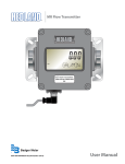
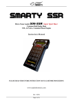
In-line Pneumatic Flow Meter Installation & Maintenance Instructions FORM #HLIT 208-2G DIVISION OF RACINE FEDERATED INC. 8635 Washington Avenue • Racine • Wisconsin 53406-3738 TEL 1-800-HEDLAND • FAX 1-800 CHK-FLOW I. INTRODUCTION The In-line Pneumatic Flow Meter is a rugged industrial class flow rate indicator, offered in aluminum, brass, T303 and T316 stainless steel models to monitor pressurized air lines and/or a wide range of other compressed gases. Available in seven port sizes from ¼” to 3” for flow ranges from 0.5-5 scfm (0.2-2.2 l/sec) through 200-2200 scfm (75-1130 l/sec), meters are calibrated at 1.0 specific gravity. In addition to the basic model, the aluminum, brass and T303 stainless steel models are offered in 3 other configurations: an extended inlet cap fitted with a pressure gauge, an extended inlet cap with a ¼” NPTF plugged gauge port, and a test kit with an extended inlet cap fitted with a 160 psi pressure gauge and control valve on the outlet. The Flow Meter is equipped with a 360° rotatable guard/scale which allows the meter to be installed in any orientation without regard to scale direction. Once the meter is permanently installed, the guard/scale can be rotated 360° to optimize readability. The unique spring loaded design of this variable area flow meter allows it to be installed in any position, including inverted, without affecting accuracy. An optional inverted scale is available for these applications. Aluminum models are offered as a rugged, low cost flow meter for monitoring noncorrosive pneumatic systems under operating pressures up to 1000 psi (69 bar), 250 psi (17 bar) for 3” models, and 600 psi (41 bar) for test kits. Brass meters are recommended for applications with operating pressures up to 1000 psi (69 bar) where corrosion inhibitors are not present. Stainless Steel is available for monitoring systems operating at pressures up to 1500 psi (103 bar). The all T316 stainless steel models are recommended for monitoring caustic or corrosive gases, such as hydrogen chloride or sulfur dioxide. The T303 stainless steel test kit is rated to 600 psi (41 bar); presure rating is limited by the valve. For further construction material information, see “Fluid Selection Chart” in the Appendix. Page 1 In-Line Pneumatic Flow Meter Installation & Maintenance Instructions II. OPERATING PRINCIPLE The Flow Meter is a variable area instrument. A sharp-edged Orifice, located within the Piston Assembly, forms an annular opening with the contoured Metering Cone. The piston assembly carries a cylindrical PPS/Ceramic Magnet that is magnetically coupled to an external Indicating Magnet which moves precisely in direct response to movement of the piston. A calibrated Spring opposes flow in the forward direction. Page 2 The Hedland variable area flow meters are the most readable products in their class. Brightly colored indicators move over the graduated, linear Flow Scale which contains bold, easy to read numeral and gauge marks. The enhanced resolution virtually eliminates parallax problems associated with competitive, direct reading flow meters. Form #HLIT 208-2G 11/10 In-line Pneumatic Flow Meter Installation & Maintenance Instructions III. SPECIFICATIONS Temperature Range • Standard: -20 to +240 °F (-29 to +116 °C) • Hostile Environment: -20 to +400 °F (-29 to +205 °C) Continuous; +400 to +500 °F (+205 to +260 °C) Intermittent • See Appendix for Pressure vs. Temperature correlation information Pressure Rating (10:1 safety factor) • Aluminum/Brass Models: 1000 psi (69 bar) maximum 3” Sizes; 250 psi (17 bar) maximum • Stainless Steel Models: 1500 psi (103 bar) maximum • Test Kit Models - Aluminum/Brass/SS: 600 psi (41 bar) maximum Pressure Drop • See Appendix for specific meter information Accuracy • ±2% of full scale Repeatability • ±1% Threads • SAE J1926/1, NPTF ANSI B2.2, BSPP ISO1179, BSPT (BS21) Test Kit Pressure Gauge - Glycerin Dampened • 0-160 psi (0-10 bar) Test Kit Load Valve • Ball valve with chrome-plated brass ball and Teflon® seals Dimensions • See Appendix Materials of Construction Basic Flow Meters and Test Kits Body Piston Cone Spider Plate Spring Fasteners T316SS T302SS Pressure Seals Guard Retaining Ring Retaining Spring Indicator & Internal Magnet Guard Seal/Bumper Scale Support End Caps Viton® Polycarbonate T316SS T316SS PPS/Ceramic Buna N 6063-T6 Aluminum Nylon ST 2024-T351 Anodized Alumininum C360 Brass 1 T303SS 2 T303SS 2024-T351 Anodized Alumininum 1 3 Inch models have Celcon® piston/piston ring 2 3 Inch models not available in T303SS Caustic and Corrosive Air and Gases - Standard Model Body Piston Cone T316SS Spider Plate Spring Fasteners T316SS T316SS T316SS Pressure Seals Guard Retaining Ring Retaining Spring Indicator & Internal Magnet Guard Seal/Bumper Scale Support End Caps Viton® Polycarbonate T316SS T316SS PPS/Ceramic Buna N 6063-T6 Aluminum Nylon ST Bumper Scale Support End Caps T316SS T316SS T316SS Caustic and Corrosive Air and Gases - Hostile Environment Model Body Piston Cone T316SS Form #HLIT 208-2G 11/10 Spider Plate Spring Fasteners T316SS T316SS T316SS Pressure Seals Guard Retaining Ring Retaining Spring Viton® Cylindrical Pyrex® Glass T316SS T316SS Indicator & Internal Magnet Indicator: T416SS Magnet: Teflon® Coated Alnico 8 Page 3 In-Line Pneumatic Flow Meter Installation & Maintenance Instructions IV. INSTALLATION CAUTION CAUTION This product should be installed and serviced by technically qualified personnel trained in maintaining industrial class flow instrumentation and processing equipment. This meter may contain residual amounts of test fluid at the time of shipment. This fluid should be removed prior to installation as the fluid may be incompatible or hazardous with some liquids or gases. Failure to follow these instructions could result in damage to the equipment. CAUTION Read instructions thoroughly before installing the unit. If you have any questions regarding product installation or maintenance, call your local supplier for more information. CAUTION A line snubber is recommended for applications in which rapid valve actuation or pulsation is anticipated. This not only reduces the risk of decoupling the flow meter’s magnetic piston, it also reduces excessive wear on other components in the system. CAUTION This standard meter is unidirectional. Attempts to flow fluids in the opposite direction of the flow arrow will result in the meter acting as a check valve, creating a deadheading situation. If the differential pressure magnitude is great enough, damage to the internal parts of the meter will result. Compressiblity of Gases Since gases are significantly compressible, the density of any compressed gas will vary according to changes in operating pressure levels. In other words, volumetric flow rates will vary significantly with changes in line pressure. Therefore, pneumatic flow meters should be installed with a pressure gauge located as close as possible to the inlet port. The psig range capacity of this pressure gauge should be at least 125% of the anticipated pressure in the system, or be suitable for the maximum expected line pressure (if higher). For example, if the anticipated operating pressure is 100 psig, a pressure gauge with a capacity of at least 125 psig should be installed as close as possible to the inlet port. Page 4 Form #HLIT 208-2G 11/10 In-line Pneumatic Flow Meter Installation & Maintenance Instructions Installation Recommendations The in-line flow meter is a simple device to install. However, the following measures are recommended for reliable, trouble-free operation: Do - Align pipe accurately. Piping should be accurately aligned and of correct length. The high pressure body of the flow meter can withstand shock and flow/pressure pulsation. However, the piping should be firmly supported by external mounting brackets, both upstream and downstream of the meter, to avoid any pipe flexing actions that could reduce meter life. Do - Use rigid mounting. If the flow meter inlet or outlet are to be rigidly mounted, and the opposing port is to be connected to flexible hose, the end connected with the flexible hose must be rigidly mounted. Do - Use Teflon® tape for sealing NPT fitting. Do - Install unions. Install a union near the inlet or outlet of the meter. This will facilitate quick, easy meter removal and inspection during periodic maintenance procedures. Do - Mount the meter either horizontally or vertically (flow arrow pointing to either side or straight up). If the meter must be mounted inverted, special inverted scales are available from the factory. Do - Ensure the fluid is traveling in the direction of the flow arrow (Figure 3 on page 6). Form #HLIT 208-2G 11/10 Do - Use at least a 200 mesh (74 micron) filter. The meter will allow particulate to pass that would jam most valves and flow controls. Systems that do not have filtration should be equipped with at least a 200 mesh (74 micron) filter. Most systems already have much finer filtration. Dirt, ferrous metal or sealing agents, such as Teflon® tape may lodge and cause malfunction. If the meter is jammed at a fixed position, follow cleaning and maintenance instructions. Don’t - Use thread locking compounds as thread sealant. Don’t - Install the flow meter near turbulence producing fittings such as elbows, reducers, close coupled valves, etc. The in-line flow meter does not require flow straighteners or special lengths of straight inlet/outlet piping to stabilize turbulent flow patterns. However, to assure maximum operational reliability, avoid installation of elbows, valves and/or reducers immediately adjacent to the meter inlet. Don’t - Install the meter near fast-acting valves. Fast-acting valves have the potential to create high magnitude hydraulic pressure spikes. These spikes can damage the internal components of the meter, resulting in inaccuracies or malfunction. Don’t - Allow unidirectional meters to be operated against the direction of the flow arrow. The standard flow meter is an unidirectional flow meter. The piston acts as a check valve to block flow in the reverse direction. This causes an excessive pressure differential, which can result in damage to internal meter components. Page 5 In-Line Pneumatic Flow Meter Installation & Maintenance Instructions Installing the Flow Meter 1. Mount the meter so fluid is traveling in the direction of the flow arrow. See Figure 3. 2. Select a mounting location that is suitable for viewing and product service. To connect the flow meter into the piping system, place an open-ended wrench onto the flow meter wrench flats adjacent to the pipe connection being installed. DO NOT wrench on the opposite end of the flow meter or leakage may result. See Figure 4. Place wrench on meter flats on the same side plumbing is being tightened 3. After installation, rotate meter by hand to view flow scale. See Figure 5. Flow Direction Arrow Never place wrench on meter flats opposite plumbing being tightened Figure 4. Installing Meter AIR Figure 3. Flow Direction Arrow Rotate meter by hand to view flow scale Never use wrench to rotate meter body when viewing flow scale Figure 5. Rotating Meter Page 6 Form #HLIT 208-2G 11/10 In-line Pneumatic Flow Meter Installation & Maintenance Instructions Installing the Test Kit Flow Meter 1. Mount the VA High Pressure Test Kit Flow Meter so fluid is traveling in the direction of the flow arrow. See Figure 3 on page 6. 2. Install the test kit at any location in the pneumatic circuit that is suitable for viewing. To connect the test kit into the piping system, place an open-ended wrench onto the test kit extended cap on the inlet side or on the test kit wrench flat on the outlet side adjacent to the pipe connection being installed. DO NOT wrench on the opposite end of the test kit or leakage may result. See Figure 6. Or, use quick disconnect couplings for easy connections and to keep the test kit sealed and clean when not in use. 3. After installation, rotate meter by hand to view flow scale. See Figure 7. Place wrench on valve body on the same side plumbing is being tightened Never place wrench on valve body opposite plumbing being tightened Figure 6. Installing Test Kit Rotate meter by hand to view flow scale Never use wrench to rotate meter Figure 7. Rotating Test Kit Form #HLIT 208-2G 11/10 Page 7 In-Line Pneumatic Flow Meter Installation & Maintenance Instructions IV. OPERATION Multi-Pressure Flow Scales The in-line pneumatic flow meter is offered with a multi-pressure flow scale to visually indicate air flow rates in standard cubic feet per minute (scfm) at 1.0 s.g. (70 °F at 100 psi) or liters per second (l/sec) at 1.0 s.g. (21 °C at 6.9 bar). The multi-pressure scale design allows for use at line pressures from 40 to 130 psi in 10 psi increments (3.0 to 9.0 bar in 1 bar increments). This configuration requires that a pressure gauge be installed at the meter inlet. The operator reads the inlet gauge pressure, selects the appropriate vertical line or interpolated value closest to the gauge reading and follows the line until it intersects the brightly colored horizontal indicator bar. The flow rate is read by taking the intersection points, following the slope of the closest diagonal line to a scale value and interpolating the scfm (l/sec) flow rate. No further calculations are required. See Figure 8. Single Pressure Flow Scales An optional single pressure flow scale is available in U.S. or metric units. This graduated scale is calibrated for air in standard cubic feet per minute (scfm) at 1.0 s.g. (70 °F at 100 psi), or liters per second (l/sec) at 1.0 s.g. (21 °C at 6.9 bar). See Figure 9. A standard cubic foot of air is defined as a cubic foot of air at 70 °F at atmospheric pressure 14.7 psia at sea level. Since it is impossible to flow air at “standard” conditions, the scale is calibrated for an inlet condition of 100 psi (6.9 bar) at 70 °F (21 °C). A correction factor must be calculated to determine the actual air volume. Each meter is supplied with the Conversion Chart shown in Figure 10. SCFM 100 PSIG @ 70 ºF 25 25 25 20 20 20 15 15 15 10 10 10 5 3 5 3 5 3 AIR FIGURE 9 Single pressure Flow Scale Application Information FIGURE 8 Multi-Pressure Flow Scale Page 8 Compressibility of Gases Since gases are significantly compressible, their density varies with pressure and temperature. Tables 1 & 2 of the Conversion Chart are used to convert “indicated” scfm flow rates to “actual” scfm flow rates for your application. Form #HLIT 208-2G 11/10 In-line Pneumatic Flow Meter Installation & Maintenance Instructions To adjust for Pressures beyond (above or below) scale limits: 1. Locate point at which the brightly colored indicator line intersects the vertical 100 psig pressure line. 2. Divide this reading by the Pressure Correction Factor (f1) indicated in the conversion Chart. Effects of Specific Gravity Standard scales are calibrated for air with a specific gravity of 1.0. Table 3 of the Conversion Chart is used to calculate “actual” scfm flow rates of gases with a specific gravity other than 1.0. Conversion Chart The Conversion Chart provides a series of simplified mathematical formulas to “correct” the graduated scale for changes in pressure (Table 1), temperature (Table 2), and/or specific gravity (Table 3). Special scales can be made to accommodate other pressures, temperatures and specific gravity. The Conversion Chart can also be used to “correct” (adjust) the Multi-Pressure Flow Scale to indicate flow rates in applications beyond the parameters stated on the scale. To adjust for changes in Temperature: 1. Divide the 100 psig flow rate reading by Temperature Correction Factor (f2). To adjust for changes in Specific Gravity: 1. Establish the square root of the new specific gravity. 2. Divide the 100 psig flow rate reading by the Specific Gravity Correction Factor (f3). DETERMINE FLOW RATES USING DIFFERENT PRESSURE & TEMPERATURES scfm (actual) = Where f1 = Conversion factor for inlet pressure f2 = Conversion factor for temperature f3 = Conversion factor for specific gravity scfm (indicated) f1 x f2 x f3 TABLE 1 - PRESSURE CORRECTION FACTOR (f1) Operating Pressure psig 25 50 75 100 125 150 175 200 225 250 bar 1.7 3.5 5.2 6.9 8.6 10.4 12.1 13.8 15.5 17.2 kPa 172 345 517 689 862 1034 1207 1379 1551 1724 1.700 1.331 1.131 1.000 0.902 0.835 0.778 0.731 0.692 0.658 f1 f1 = √ 114.7 14.7 + psig f1 = √ 7.914 1.014 + bar f1 = √ 790.857 101.357 + kPa TABLE 2 - TEMPERATURE CORRECTION FACTOR (f2) Operating Temperature °F +10 +30 +50 +70 +90 +110 +130 +150 +170 °C -12.2 -1.1 +909 +21.0 +32.1 +43 +54 +65 +76 +88 f2 .942 .962 .981 1.000 1.018 1.037 1.055 1.072 1.090 1.107 f2 = √ 460 + °F 530 f2 = √ +190 273 + °C 293 TABLE 3 - SPECIFIC GRAVITY CORRECTION FACTOR (f3) f3 = √ SP. GR. FIGURE 10 Conversion Chart Form #HLIT 208-2G 11/10 Page 9 In-Line Pneumatic Flow Meter Installation & Maintenance Instructions VI. MAINTENANCE WARNING Before attempting to remove the flow meter from the line, check the system to confirm that line pressure has been reduced to zero PSI. Failure to follow these instructions could result in serious personal injury or death and/ or damage to the equipment. 1. Remove the flow meter from the line. Remove excess piping from meter. NOTE: It is not necessary to remove the transparent dust guard from the meter to remove the meter from the line. If you choose to remove the dust guard assembly, refer to Removal of Dust Guard section. 2. Thoroughly wipe off the entire flow meter surface using mild detergent or isopropyl alcohol. CAUTION D o n o t u s e a ro m a t i c hyd ro c a r b o n s, halogenated hydrocarbons, ketones or ester based fluids on polycarbonate lens. Failure to follow these instructions could result in damage to the meter. 3. Remove the inlet cap from the flow meter, noting the sequence of disassembly for later reference (during reassembly). 4. The internal parts are secured with a retaining ring. Remove the retaining ring and the internal wetted parts from the flow meter. NOTE: If internal parts do not slide freely from flow meter, use a wooden dowel inserted into the outlet port of the meter to push parts out. Page 10 5. Place all parts on a clean work surface. Clean and inspect all parts. Replace any that appear worn or damaged. Check inlet port O-ring for damage and replace if required. CAUTION Fiel d repl acem ent o f the s pr ing, m e te r i n g co n e a n d / o r p i s to n / m a gn e t a s s em bl y m ay res u l t in c hang es to the calibration of the flow meter. 6. Reassemble spring, then piston/magnet assembly and retaining ring into flow meter. 7. Install metering cone/spider plate assembly, retaining spring, and secure with inlet cap. 8. Reinstall meter to the line. Removal of Dust Guard To remove the dust guard for cleaning or replacement, simply loosen the end fitting located at the bottom of the meter and slide the end cap, dust bumper, and the dust guard off the bottom of the meter, taking care to avoid damaging the O-ring seal between the end cap and the dust gland. Quick Re-Coupling This piston-type variable area flow meter is inherently less sensitive to shock and vibration than other variable area designs. The unique magnetic coupling also eliminates the need for mechanical linkages that can wear or loosen over the functional life of the meter. However, on occasion, a pressure spike or extreme flow surge can cause the piston to Form #HLIT 208-2G 11/10 In-line Pneumatic Flow Meter Installation & Maintenance Instructions EPR Viton® External Pressure Seals R R R R R R R R R R R R R R R R R R R R R R R R R R R R R R R R R R R C R C R N C R R R R R R R R R R R R R N C - Consult Factory Dust Guard Pyrex Air 1.00 1.000 R Argon (A) 1.38 1.175 R Carbon Dioxide (CO2) 1.53 1.237 R Freon 11 (CCI3F) 4.92 2.218 R Freon 12 (CCI2F) 4.26 2.060 R Helium (HE) 0.14 0.374 R Hydrogen (H2) 0.07 0.265 R Natural Gas 0.60 0.775 C Nitrogen (N2) 0.97 0.985 C Oxygen (O2) 1.10 1.049 R Propane (C3H8) 1.57 1.253 R R - Recommended N - Not Recommended T303SS Specific Correction Gravity Factor of Standard Scale T316SS Fluid Brass Internal Body Material Nylon Load Valve If the valve fails to load the system, remove the valve body and check for foreign material, worn parts or seals. Fluid Selection Chart Polycarbonate Test Kit Maintenance VII. APPENDIX Aluminum move at such rapid speed that it disconnects the piston magnet and the external indicator ring. If this occurs, use one of these procedures to recouple the magnet and the external indicator ring: • If the system permits, simply change flow rate from “no flow” to “full flow” allowing the moving piston to magnetically recouple to the indicator ring. • For rigorous cyclical applications where de-coupling may occur frequently, consult the technical services staff for further recommendations. R R R R R R R C R R N R R R R R R R R R R R R R R R R R R R R R R Pressure vs. Temperature Chart Flow The absence of any flow reading may indicate a seized piston assembly. Remove any material that may be preventing the piston to slide. If the Test Kit still fails to indicate flow, it is recommended to return the Test Kit to the factory. For return procedures, see the Return Goods Authorization section of this manual on page 15. Form #HLIT 208-2G 11/10 Page 11 In-Line Pneumatic Flow Meter Installation & Maintenance Instructions Flow vs. Pressure Drop * Air / Compressed Gases 3-30 ¼" PRESSURE DROP, PSI 2-20 PRESSURE DROP, PSI 15-150 ½" 1-10 0.5-5 10-100 5-50 3-25 FLOW, SCFM FLOW, SCFM 100-1000 1-¼" / 1-½" PRESSURE DROP, PSI PRESSURE DROP, PSI ¾" / 1" 25-250 10-100 15-150 3-25 80-800 60-600 40-400 20-200 5-50 FLOW, SCFM FLOW, SCFM 3" 200-2200 PRESSURE DROP, PSI 100-1400 FLOW, SCFM * 1. The pressure drop curves are valid for fluids with density and viscosity similar to factory test fluids. Fluids, especially with higher viscosity than these test fluids, will yield a higher pressure drop through the flow meter and piping system per a given flow volume. 2. A system must have adequate fluidic horsepower available to move the system fluid at a prescribed rate at a pressure adequate to overcome all pressure reducing devices – including the flow meter. Page 12 Form #HLIT 208-2G 11/10 In-line Pneumatic Flow Meter Installation & Maintenance Instructions Air / Compressed Test Kits 3-30 ¼" PRESSURE DROP, PSI 2-20 PRESSURE DROP, PSI 15-150 ½" 1-10 0.5-5 10-100 5-50 3-25 FLOW, SCFM FLOW, SCFM 100-1000 1-¼" / 1-½" 25-250 10-100 15-150 3-25 PRESSURE DROP, PSI PRESSURE DROP, PSI ¾" / 1" 80-800 60-600 40-400 20-200 5-50 FLOW, SCFM FLOW, SCFM Air / Caustic and Corrosive Gases 3-30 ¼" 15-150 ½" PRESSURE DROP, PSI PRESSURE DROP, PSI 2-20 10-100 5-50 3-25 FLOW, SCFM FLOW, SCFM 100-1000 1-¼" / 1-½" 25-250 10-100 15-150 3-25 PRESSURE DROP, PSI PRESSURE DROP, PSI ¾" / 1" 80-800 60-600 40-400 20-200 5-50 FLOW, SCFM Form #HLIT 208-2G 11/10 FLOW, SCFM Page 13 In-Line Pneumatic Flow Meter Installation & Maintenance Instructions Dimensions Standard Meters: ¼ to 1-½ inch models A Nominal Port Size B Length in (mm) B1 Length in (mm) C Width in (mm) D Depth in (mm) E Offset in (mm) F Flats in (mm) G Height in (mm) ¼ (SAE 6) 4.80 (122) 6.12 (155) 1.68 (43) 1.90 (48) .82 (21) .88 (22) 5.00 (127) ½ (SAE 10) 6.60 (168) 8.00 (203) 2.07 (53) 2.40 (61) 1.04 (26) 1.25 (32) 5.40 (137) ¾ (SAE 12) 7.20 (183) 8.90 (226) 2.48 (63) 2.85 (72) 1.24 (32) 1.50 (38) 5.90 (150) 1 (SAE 16) 7.20 (183) 8.90 (226) 2.48 (63) 2.85 (72) 1.24 (32) 1.75 (44) 5.90 (150) 1-¼ (SAE 20) 12.20 (310) 13.80 (351) 4.12 (105) 4.72 (120) 2.06 (52) 2.75 (70) 7.20 (183) 1-½ (SAE 24) 12.20 (310) 13.80 (351) 4.12 (105) 4.72 (120) 2.06 (52) 2.75 (70) 7.20 (183) A G D E F C B1 B Standard Meter Standard Meter with EP & EG Option 3 inch; SAE, NPTF, BSPT models - Inches (mm) 5.75 (146.0) 4.50 (114.3) Across Flats 3” Ports 16.18 (411) Page 14 Form #HLIT 208-2G 11/10 In-line Pneumatic Flow Meter Installation & Maintenance Instructions Test Kits: A Nominal Port Size B Length in (mm) B1 Length in (mm) C Width in (mm) D Depth in (mm) E Offset in (mm) F Flats in (mm) ½ (SAE 10) 6.60 (168) 9.60 (245) 2.07 (53) 2.40 (61) 1.04 (26) 1.25 (32) ¾ (SAE 12) 7.20 (183) 10.70 (272) 2.48 (63) 2.85 (72) 1.24 (32) 1.50 (38) 1 (SAE 16) 7.20 (183) 10.70 (272) 2.48 (63) 2.85 (72) 1.24 (32) 1.75 (44) 1-¼ (SAE 20) 12.20 (310) 20.50 (521) 4.12 (105) 4.72 (120) 2.06 (52) 2.75 (70) 1-½ (SAE 24) 12.20 (310) 20.50 (521) 4.12 (105) 4.72 (120) 2.06 (52) 2.78 (70) A G C B F B1 (Ref. Dim.) E D Return Goods Authorization When returning equipment for service, a Returned Goods Authorization (RGA) number must be obtained from our Service Department. Please contact them by phone at 800-433-5263 or 262-639-6770 or by e-mail to [email protected]. All returns go to the following address and must include the RGA number on the outside of the box: Hedland Division of Racine Federated Inc. 8635 Washington Avenue Racine, WI 53406-3738 USA Attn: RGA # xxx-xxxx Form #HLIT 208-2G 11/10 Page 15 In-line Liquid Flow Meter Installation & Maintenance Instructions LIMITED WARRANTY and DISCLAIMER Hedland, Division of Racine Federated Inc. warrants to the end purchaser, for a period of one year from the date of shipment from the factory, that all flow meters manufactured by it are free from defects in materials and workmanship. This warranty does not cover products that have been damaged due to misapplication, abuse, lack of maintenance, or improper installation. Hedland’s obligation under this warranty is limited to the repair or replacement of a defective product, at no charge to the end purchaser, if the product is inspected by Hedland and found to be defective. Repair or replacement is at Hedland’s discretion. A returned goods authorization (RGA) number must be obtained from Hedland before any product may be returned for warranty repair or replacement. The product must be thoroughly cleaned and any process chemicals removed before it will be accepted for return. The purchaser must determine the applicability of the product for its desired use and assumes all risks in connection therewith. Hedland assumes no responsibility or liability for any omissions or errors in connection with the use of its products. Hedland will under no circumstances be liable for any incidental, consequential, contingent or special damages or loss to any person or property arising out of the failure of any product, component or accessory. All expressed or implied warranties, including the implied warranty of merchantability and the implied warranty of fitness for a particular purpose or application are expressly disclaimed and shall not apply to any products sold or services rendered by Hedland. The above warranty supersedes and is in lieu of all other warranties, either expressed or implied and all other obligations or liabilities. No agent or representative has any authority to alter the terms of this warranty in any way. 8635 Washington Avenue, Racine, WI 53406-3738 USA Telephone: 262-639-6770 or 800-HEDLAND Fax: 262-639-2267 or 800-CHK-FLOW www.hedland.com [email protected] Materials & specifications are subject to change without notice. DIVISION OF RACINE FEDERATED INC. HEDLAND is a registered trademark of Racine Federated Inc. VITON is a registered trademark of DuPont Dow Elastomers. CELCON is a registered trademark of Hoeschst Celanese Corporation. PYREX is a registered trademark of Corning Glass Works Corporation. TEFLON is a registered trademark of E.I. du Pont de Nemours and Company. UL is a registered trademark of Underwriters Laboratories. Form # HLIT208-2G 11/10 © 2010 Racine Federated Inc. Printed in USA