1
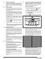
Users
Instructions
THESE INSTRUCTIONS
TO BE RETAINED
BY USER
Contents
Introduction
2
2
Things you should know
1.1
1.2
1.3
1.4
1.5
1.6
1.7
1.8
Gas appliances
Electrical supply
Guarantee registration card
Benchmark log book
How does it work?
Dimensions
Clearances required
Frost protection system
Getting started
2.1
2.2
2.3
2.4
2.5
2.6
How to...
Page
Dear customer
Do’s and don’t’s
3.1
3.2
3.3
3.4
3.5
Page
3
3
3
3
3
3
3
3
What if...
4.1
4.2
4.3
4.4
4.5
3
3
4
4
4
5
5.1
5.2
6
6
6
6
6
Page
I suspect a gas leak
I frequently have to top-up the system
The status led is red
The appliance is due its annual service
I need to call an engineer
Setting the Vokera
Page
Before switching on
Appliance controls
Lighting the boiler
Adjusting the operating temperature
Digital display
Fault code table
Page
Top-up the system pressure
Reset the appliance
Shut down the system for short periods
Shut down the system for long periods
Care for the appliance
6
6
6
6
6
Page
Mechanical clock
Digital clock
7
7
INTRODUCTION
Dear Customer
Your Vokera Pinnacle boiler has been designed to meet and exceed the very latest standards in gas central heating
technology, and if cared for, will give years of reliable use and efficiency. Please therefore take some time to read
these instructions carefully.
Do’s and don’t’s
● Do ensure that the system pressure is periodically checked
● Do ensure that you know how to isolate the appliance in an emergency
● Do ensure that you are familiar with the appliance controls
● Do ensure that your installer has completed the appliance log book
● Do not attempt to remove the appliance casing or gain internal access
● Do not hang clothes etc. over the appliance
● Do not forget to have the appliance serviced annually.
5
4
6
7
3
2
8
1
9
10
2
1=
step button
6=
reset button
2=
increase button
7=
decrease button
3=
mode button
8=
heating selector
4=
digital display
9=
clock aperture
5=
status LED
10= pressure gauge
Fig. 1
THINGS YOU SHOULD KNOW
1.1
1.2
1.3
1.4
1.5
GAS APPLIANCE
Gas Safety (Installations and Use) Regulations.
In the interests of your safety and that of others it
is a legal requirement that all gas appliances are
installed and correctly maintained by a competent
person and in accordance with the latest
regulations.
ELECTRICAL SUPPLY
Please ensure that this appliance has been
properly connected to the electrical supply by
means of a double pole isolator or un-switched
socket, and that the correct size of fuse (3 amp)
has been fitted.
Warning: this appliance must be earthed!
GUARANTEE REGISTRATION CARD
Please take the time to fill out your guarantee
registration card. The completed warranty card
should be posted within 30 days of installation.
BENCHMARK LOG BOOK
The Benchmark Log Book is supplied with your
boiler. This important document must be
completed during the installation/commissioning
of your boiler. All CORGI Registered Installers
carry a CORGI ID card and have a registration
number. Both should be recorded in your
Benchmark Log Book. You can check your
installer by calling CORGI direct 01256 372300.
Failure to install and commission the appliance in
accordance with the manufacturers instructions
may invalidate the warranty. This does not affect
your statutory rights.
HOW DOES IT WORK?
Your Pinnacle boiler is a high efficiency central
heating boiler, which supplies heated water to
your radiators and hot water cylinder.
The central heating and hot water is controlled via
a programmer and any thermostats that your
installer may have fitted. The Pinnacle boiler
lights electronically and does not have a pilot
light. In the unlikely event of a fault developing
with your boiler, the supply of gas to the burner
will be terminated automatically.
1.6
DIMENSIONS
HEIGHT
WIDTH
DEPTH
1.7
CLEARANCES REQUIRED
ABOVE
BELOW
SIDES
FRONT
1.8
820 mm
450 mm
355 mm
150 mm
120 mm
12 mm
600 mm
FROST PROTECTION SYSTEM
The Pinnacle is equipped with a built-in frost
protection system, this enables the boiler to override the time controls – if switched off – and
operate the burner and/or pump, should the
temperature drop below 7 °C.
Please note that the frost protection system is
designed to protect the appliance only, should
frost protection be required for the central heating
system, additional controls may be required.
NOTE
The frost protection system is reliant on the
appliance having a permanent electrical supply,
and being in a non-fault condition.
GETTING STARTED
2.1
BEFORE SWITCHING ON
Before switching the appliance on please
familiarise yourself with:
● how to isolate the appliance from the gas,
water, and electricity supplies;
● how to check and top-up – if necessary – the
system water pressure;
● the time clock or programmer;
● any external thermostats and their functions;
● the appliance controls.
2.2
APPLIANCE CONTROLS (fig. 1)
The appliance controls are concealed behind the
front cover. To gain access to the controls simply
press the cover inwards to release the catch. The
appliance is equipped with a simple keypad that
can be used to alter the following function:
the outlet flow temperature to the central heating
system and hot water cylinder;
The pressure gauge shows the current pressure
of the system, the gauge should be set between
1 and 1.5 bar. When the appliance is operating
the gauge may rise or fall slightly, this is quite
normal. The minimum permissible level for the
safe and efficient operation of the appliance is 0.5
bar. Should the pressure fall below 0.5 bar, the
boiler may lockout.
Depending on the type of controls specified by
your installer you may have an integral Vokera
time clock fitted to the appliance, if so, instructions
can be found on page 8-9. If an external time
clock or programmer has been fitted, please refer
to the instructions supplied with such.
●
3
2.3
2.3.1
LIGHTING THE BOILER
Ensure the gas and electrical supply to the boiler
are turned on. The boiler will now go through a
self-test and purge sequence indicated by the
letter ‘A’ shown on the left side of the digital
display.
ON/OFF MODES
The heating mode can be switched ON or OFF
at the boiler irrespective of the current
programmer setting. This is indicated by the
status LED (fig. 1).
If the status LED is permanently illuminated green,
this indicates that the heating mode is enabled
and is controlled via the programmer and any
external controls such as a room thermostat or
cylinder thermostat.
If the status LED is flashing green, the boiler will
not respond to any heat requests from the
programmer or room thermostat etc. (only frost
protection is active).
To switch the heating mode ON or OFF, press
and hold the
2.3.3
4
ADJUSTING THE OPERATING TEMPERATURE
Usually your installer will have adjusted the
operating temperatures to suit your requirements,
however should you wish to view or alter them,
please use the following procedure:
Operating temperature
● to view or alter the heating operating
temperature, briefly press the
●
●
button;
the operating temperature will be shown on the
right side of the display (see fig. 2);
use the + or
- button to adjust the operating
temperature if required;
●
press the
button to save the new setting.
button (fig. 2) whilst looking at
the digital display:
● c OF indicates the heating mode is switched
OFF
● c 55 (or any other number, indicating the central
heating operating temperature), indicates the
heating mode is switched ON.
2.3.2
2.4
HEATING REQUEST
When there is a demand for heating via the
programmer, the boiler will go through an ignition
sequence, whereby the burner will light. When
the appliance reaches the set temperature, the
burner will go off for minimum period of
approximately 90 seconds. When the
programmer/time clock or external thermostats
heating request has been satisfied, the appliance
will switch off automatically.
NOTE
If the appliance fails to ignite during the ignition
sequence, it will re-attempt ignition several times
before going to a lockout condition. Should this
occur, please allow a period of two minutes
before re-setting.
STATUS LED (fig. 1)
The appliance status LED indicates whether the
boiler is in OFF mode, ON mode or fault condition.
Status LED flashing Green
Indicates the appliance is in the OFF mode, with
electrical supply and frost protection active.
Status LED permanently Green*
Indicates the appliance is ON mode, with heating
or hot water or both activated.
Status LED permanently Red
This indicates that the appliance is in a permanent
fault condition and may require to be reset
(indicated by the relevant fault code displayed)
see section 2.6.
*Also illuminated during a temporary fault
condition.
Fig. 2
2.5
DIGITAL DISPLAY
The digital display shows the current mode of
operation and/or status of the boiler.
Should a fault develop, the display will show a
unique fault code that can be used to help rectify
the cause of the fault. During the normal operation,
the left side of the display indicates the current
mode of operation, whilst the right side will show
the current temperature.
Left display shows
0
1
2
3
4
5
6
7
8
A
Current status
Stand-by mode
Purging
Ignition
Heating mode
N/A
Fan operation
Timer delay
Pump over run
N/A
Self check
Displays during normal operation
Should a fault occur, the left side of the display will
show whether the fault is temporary or permanent
(indicated by ‘b’ or ‘E’), whilst the right side of the
display indicates the unique fault code.
Should a fault code be displayed, check the
fault code table to identify the cause and
course of action to take. Always wait 2minutes before pressing the reset button.
2.6
FAULT CODE TABLE
Code
E 00
E 02
E 03
E 04
E 05
E 06
E 07
E 11
E 12
E 13
E 14
E 15
E 16
E 17
B 18
E 18
B 19
E 19
B 24
B 25
E 25
B 26
B 28
E 28
B 29
E 29
B 30
E 30
E 31
E 32
E 33
E 36
E 37
E 38
E 44
E 60
B 65
Reason
Ignition anomaly
No flame detected
Internal fault
Power failure
Internal fault
Internal fault
Internal fault
Internal fault
Appliance overheat
Internal fault
Internal fault
Internal fault
Internal fault
Internal fault
Appliance overheat
Appliance overheat
Appliance overheat
Appliance overheat
Temperature anomaly
Temperature anomaly
Temperature anomaly
Condensate pipe blocked
Insufficient fan speed
Fan problem
Fan speed problem
Fan problem
Temperature anomaly
Temperature anomaly
Internal fault
Internal fault
Internal fault
Internal fault
Internal fault
Internal fault
Internal fault
Programming fault
Insufficient fan speed
Action required
Reset appliance, if fault continues, call engineer
Check gas is on, reset appliance, if fault continues, call engineer
Call engineer
Reset appliance, if fault continues, call engineer
Call engineer
Call engineer
Call engineer
Call engineer
Reset appliance, if fault continues, call engineer
Call engineer
Call engineer
Call engineer
Call engineer
Call engineer
Ensure radiators are on
Reset appliance, if fault continues, call engineer
Ensure radiators are on
Reset appliance, if fault continues, call engineer
If fault continues, call engineer
Check pressure gauge
Check pressure gauge, reset appliance, if fault continues, call engineer
Check outlet of condense pipe, if problem persists, call engineer
If fault continues, call engineer
Reset appliance, if fault continues, call engineer
If fault continues, call engineer
Reset appliance, if fault continues, call engineer
Check pressure gauge
Check pressure gauge, reset appliance, if fault continues, call engineer
Call engineer
Call engineer
Call engineer
Call engineer
Call engineer
Call engineer
Call engineer
Call engineer
If fault continues, call engineer
5
HOW TO...
3.1
HOW TO TOP-UP THE SYSTEM PRESSURE (fig. 3)
The system pressure must be checked periodically
to ensure the correct operation of the boiler. The
needle on the gauge should be reading between
1 and 1.5 bar when the boiler is in an off position
and has cooled to room temperature. If the
pressure requires ‘topping-up’ use the following
instructions as a guide.
● Locate the filling valve connections (usually
beneath the boiler).
● Attach the temporary filling connection to both
control vales.
● Open both control valves slowly until you hear
water water entering the system.
● Close the control valves when the pressure
gauge (on the boiler) reads between 1 and 1.5
bar.
● Remove the temporary connection from the
control valves.
3.2
HOW TO RESET THE APPLIANCE
When the status light is illuminated red, the
appliance will require to be reset manually. Before
resetting the boiler ensure that the pressure
gauge is indicating the correct level. Allow a
period of two minutes to elapse before pressing
the reset button.
IMPORTANT
If the appliance requires to be reset frequently, it may
be indicative of a fault, please contact your installer or
Vokera Customer Services for further advice.
3.3
HOW TO SHUT DOWN THE SYSTEM FOR
SHORT PERIODS
The system and boiler can be shut down for short
periods by simply turning the time clock to the off
position. It is also advisable to turn off the main
water supply to the house.
3.4
HOW TO SHUT DOWN THE SYSTEM FOR
LONG PERIODS
If the house is to be left unoccupied for any length
of time – especially during the winter – the system
should be thoroughly drained of all water.
The gas, water and electricity supply to the house
should also be turned off. For more detailed
advice contact your installer.
3.5
HOW TO CARE FOR THE APPLIANCE
To clean the outer casing use only a clean damp
cloth. Do not use any scourers or abrasive
cleaners.
4.4
WHAT IF THE APPLIANCE IS DUE ITS
ANNUAL SERVICE
Advice for tenants only
Your landlord should arrange for servicing.
Advice for homeowners
Please contact Vokera Customer Services (0870
333 0220 (UK) or 05655057 (ROI) if you would
prefer a Vokera service engineer or agent to
service your appliance. Alternatively your local
CORGI registered engineer may be able to service
the appliance for you.
4.5
WHAT IF I NEED TO CALL AN ENGINEER
If you think your boiler may have developed a
fault please contact your installer or Vokera
Customer Services (0870 333 0220 (UK) or
05655057 (ROI) have all your details to hand
including full address and postcode, relevant
contact numbers, and your completed appliance
log book.
control valve
temporary
connection
flow/return
pipe
double check
valve
control valve
supply pipe
Fig.3
WHAT IF...
4.1
WHAT IF I SUSPECT A GAS LEAK
If you suspect a gas leak, turn off the gas supply
at the gas meter, and contact your installer or
local gas supplier. If you require further advice
please contact your nearest Vokera office.
4.2
WHAT IF I HAVE FREQUENTLY TO TOP-UP
THE SYSTEM
If the system regularly requires topping-up, it may
be indicative of a leak. Please contact your installer
and ask him to inspect the system.
4.3
WHAT IF THE STATUS LED IS RED
If the reset light is on it indicates that the boiler has
failed to ignite or has overheated, when this
happens the boiler automatically shuts down and
requires to be reset manually (see section 3.2).
6
VOKERA TIMECLOCKS
5.1
VOKERA MECHANICAL CLOCK
Setting the time
The time of day can be set by grasping the outer
edge of the black dial and turning it in a clockwise
direction until the correct time is in line with the
white pointer.
Setting the ‘switching times’
The ‘ON’ periods are set by sliding the black
tappets, adjacent to the time periods required, to
the outer edge of the dial.
The tappets that remain at the centre of the dial
will be the ‘OFF’ periods.
The smallest switching time (ON or OFF) is 15
minutes.
To select ‘Timed’ mode move the selector switch
in the middle of the clock face to the ‘ ‘ position.
To select ‘Constant’ mode move the selector switch
in the middle of the clock face to the ‘I’ position.
To select ‘Off’ mode move the selector switch in
the middle of the clock face to the ‘O’ position.
VOKERA DIGITAL TIME CLOCK
Select button
Reset button
Minute button
Clock button
Day button
5.2.1
BEFORE PROGRAMMING
Gently press and release the ‘Res.’ button with a
pencil or similar, this will clear the memory of all
information. This should only be done when you
want to change or insert a complete new
programme.
5.2.2
SETTING THE TIME OF DAY
The ‘real time’ clock has to be set to the actual
day of the week and time of day, to do this:
● Press and hold the
button (see fig 7).
● Press the ‘Day’ button until the actual day
shows in the display (1= Monday, 2= Tuesday,
3= Wednesday, etc.).
● If setting the clock during ‘British summertime’
press the ‘+/-1h’ button once (use a pencil or
similar).
● Press the ‘h’ button until the actual hour is
shown in the display.
● Press the ‘m’ button until the actual minutes
are showing in the display.
● Now release the
button.
● The ‘:’ symbol between the hours and minutes
display will start to flash, this indicates that the
clock is now keeping time (see fig. 8).
Selector
switch
Fig. 5
VOKERA DIGITAL CLOCK
The Vokera digital time clock will automatically
switch your boiler on and off. It has a total of
twenty different switching commands, consisting
of ten ‘on’ commands and ten ‘off’ commands.
Each ‘on’ or ‘off’ command can be used to switch
the boiler ‘on’ or ‘off’ at the same time:
● Every day of the week
● Monday to Saturday
● Monday to Friday
● Saturday and Sunday
● Any particular day
Group of days
Mon. to Fri.
Mon. to Fri.
Sat. & Sun.
Sat. & Sun.
Fig. 7
On
Off
06.00
16.00
08.30
17.00
09.00
21.00
10.30
23.00
Total
Commands ‘free’
Commands
used
2
2
2
2
8 used
12 unused
Display
Fig. 6
OFF period
Example
Hour button
Programme
button
ON period
5.2
“British summertime”
button
5.2.3
Fig. 8
ENTERING
(on) COMMANDS
● Repeatedly press the Prog. Button until the —
:— symbol appears in the clock display (see
fig. 9).
● Press the Day button until the desired group of
days or desired day is shown.
● Press the ‘h’ button until the desired hour for
switching the boiler on is shown.
7
●
●
●
Press the ‘m’ button until the desired minutes
are shown.
Press the Select button until the
symbol is
shown (see fig. 10).
Press the
button.
Fig. 9
5.2.4
Fig. 10
ENTERING
(off) COMMANDS
● Repeatedly press the Prog. Button until the —
:— symbol appears in the clock display (fig. 5).
● Press the Day button until the desired group of
days or desired day is shown.
● Press the ‘h’ button until the desired hour for
switching the boiler off is shown.
● Press the ‘m’ button until the desired minutes
are shown.
● Press the Select button until the
symbol is
shown (see fig. 11).
● Press the
button.
Once the programming has been completed you
will have to press the Select button – once only
(on) position if the boiler has been
– to the
programmed to be ‘on’ at that particular time.
Fig. 11
5.2.5
ADVANCING OR LOCKING PROGRAMME
COMMANDS
By pressing the Select button you can advance the
time clock to the next command setting (from ‘on’ to
‘off’ or ‘off’ to ‘on’) or lock the time clock to a particular
command (‘on’ continuously or ‘off’ continuously).
●
- ON
- OFF
●
●
[
] – ON CONTINUOUSLY
[ ] – OFF CONTINUOUSLY
NOTE
The actual time can be changed to account for
British summertime by simply pressing then releasing the +/- 1h button.
HELPFUL HINTS
● You can check and/or alter the programme
settings at any time by pressing the Prog button.
● The number of unused ‘commands’ can be checked
by pressing the Prog button until FR is displayed
alongside the number of unused commands.
● In the event of a power failure, the clock has a
battery back-up. The programme will be held
in the memory for approximately 2 weeks.
Charging time is 70 hours.
● Take a note of the settings you have programmed, as local power surges can sometimes reset the memory of the clock.
●
8
NOTE
9
10
11
Cod. 10023767 - 49/03 - Ed. 2
energizing home heating
Vokèra Ltd.
4th Floor, Catherine House, Boundary Way, Hemel Hempstead, Herts, HP2 7RP
Email: [email protected] Web: www.vokera.co.uk
Sales, Technical Advice, General Enquiries - Tel: 0870 333 0520 Fax: 01442 281403
After Sales Service - Tel: 0870 333 0220
Vokèra Ireland
West Court, Callan, Co Kilkenny
Tel: 05677 55057 Fax: 05677 55060
Vokèra Ltd. reserve the right to change the specifications without prior notice. Consumers’ statutory rights are not affected.
A Riello Group Company
COLLECTIVE MARK
“Vokèra”
supports Benchmark