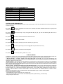
1
BURNER ADJUSTMENT
1) Burner "MINIMUM" adjustment:
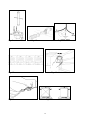
Work surface burner adjustment: follow the instructions below to adjust the work surface burner minimum:
1) Light the burner and set the knob to the MINIMUM position (small flame).
2) Remove the knob of the valve that is press fit on the rod of that valve.
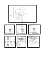
3) If the cooker is not equipped with safety valves on the surface burners, insert a small slotted screwdriver into the hole
on the valve rod (Fig. 14) and turn the choke screw to the right or left until the burner flame is adjusted to minimum. If the
cooker is equipped with safety valves, the choke valve is not located in the rod hole, but on the valve body (see fig. 15).
4) Make sure that the flame does not go out when switching quickly from the MAXIMUM to the MINIMUM position.
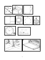
Oven burner adjustment: follow the instructions below to adjust the minimum:
WARNING: The above-mentioned adjustment should be made only with methane gas burners, while for those
operating with liquid gas the screw must be locked at the end in a clockwise direction. The grill
burner always operates at maximum and therefore no minimum adjustment is required.
APPLIANCE ELECTRIC CONNECTION:
The electric connection must comply with the current legal standards and regulations.
Before making the connection, check that:
- The system electrical rating and the current outlets are adequate for the maximum power output of the appliance (see
the label applied to the bottom of the casing).
- The outlet or the system is equipped with an efficient ground connection in accordance with the current legal standards
and regulations. The company will not be responsible for the non-compliance with these instructions.
When the connection to the power supply network is made using an outlet:
- If the power cord is supplied without a plug, apply a standard plug that is suitable for the load indicated on the label.
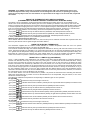
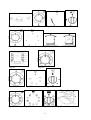
Connect the wires according to the diagram shown in FIG.17 and check that:
letter L (phase) = brown wire;
letter N (neutral) = blue wire;
= green-yellow wire;
ground symbol
- The power cord must be positioned so that an overtemperature of 75 K will not be reached at any point.
- Do not use reductions, adapters or splitters since they might cause false contacts and lead to dangerous overheating.
When the connection is made directly to the electric network:
- Use a device that ensures disconnection from the mains in which the contacts are opened to a distance that permits
complete disconnection according to the conditions for over-voltage category III.
- Remember that the ground wire must not be interrupted by the circuit-breaker.
- As an alternative, the electric connection can also be protected by a high-sensitivity residual current circuit-breaker.
- It is highly recommended to attach the special green-yellow ground wire to an efficient ground system.
WARNING: If the power cord is replaced, the ground wire (yellow-green) connected to the terminal, should be
longer than the other wires by about 2 cm.
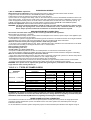
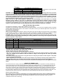
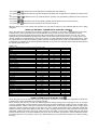
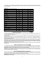
TABLE N°4 : TYPES OF POWER CORDS
Work surface
operation
Oven
operation
Only gas burner
Electric Oven
Gas burner + 1 hot plate
Ventilated Electric Oven
Electric Oven
Gas burner + 2 hot plate
4 hot plate
Ceran
230V ~
3x1mm² (M6)
3x1,5mm² (M9
3x1,5mm²
3x1,5mm² (M6)
3x2,5mm² (M9
3x2,5mm²
3x2,5mm²
3x2,5mm²
3x2,5mm²
3x2,5mm²
3x2,5mm²
3x4mm²
Ventilated Electric Oven
Forno elettrico statico
Forno elettrico ventilato multi-9
Forno elettrico statico
Forno elettrico ventilato multi-9
Forno elettrico statico
Forno elettrico ventilato multi-9
Cross section
230V 3~ 400V 2N~ 400V 3N~
-
-
-
-
-
-
4x1,5mm²
4x1,5mm²
4x1,5mm²
4x1,5mm²
4x1,5mm²
4x1,5mm²
4x1,5mm²
4x1,5mm²
4x1,5mm²
4x1,5mm²
4x1,5mm²
4x1,5mm²
5x1,5mm²
5x1,5mm²
5x1,5mm²
5x1,5mm²
5x1,5mm²
5x1,5mm²
ATTENTION: The appliance conforms with the regulations of directives 90/396EEC (Gas Directive) regarding gas
appliances for domestic use and the like, 93/68 and 73/23 (Low Voltage Directive) regarding electrical safety and
2004/108/CE, 93/68 and 89/336 (EMC Directive) regarding electromagnetic compatibility.
THREE-PHASE ELECTRIC CONNECTION
The cookers that can also be connected to three-phase systems normally are factory built for the single-phase 230V
connection and are supplied with a power cord. Based on the connection system used, install the power cord type
indicated in table No.4.
To use the selected connection system change the jumpers on the terminal strip as indicated in the diagram of Fig.18
4