1
SERVICING
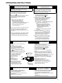
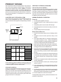
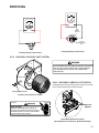
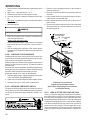
A
GAS
STREAM B
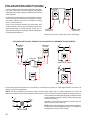
.023" - .027"
Beckett Burner
WARNING
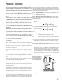
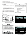
The length of Dimension "A" determines the angle of Gas
Stream "B".
DENT OR
BURR
DISCONNECT ALL GAS AND ELECTRICAL POWER SUPPLY.
In checking main burners, look for signs of rust, oversized
and undersized carry over ports restricted with foreign material, etc, refer to previous drawing. Burner cross-over slots
must not be altered in size.
S-306
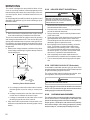
CHECKING ORIFICES
A predetermined fixed gas orifice is used in all of these
furnaces. That is an orifice which has a fixed bore and position as shown in the following drawing.
No resizing should be attempted until all factors are taken
into consideration such as inlet and manifold gas pressure,
alignment, and positioning, specific gravity and BTU content of the gas being consumed.
The only time resizing is required is when a reduction in
firing rate is required for an increase in altitude.
Orifices should be treated with care in order to prevent damage. They should be removed and installed with a box-end
wrench in order to prevent distortion. In no instance should
an orifice be peened over and redrilled. This will change the
angle or deflection of the vacuum effect or entraining of primary air, which will make it difficult to adjust the flame properly. This same problem can occur if an orifice spud of a
different length is substituted.
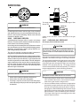
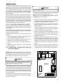
GAS
STREAM B
A dent or burr will cause a severe deflection of the gas
stream.
S-307 CHECKING GAS PRESSURE
Gas Supply Pressure Measurement
CAUTION
TO PREVENT UNRELIABLE OPERATION OR EQUIPMENT DAMAGE, THE
INLET GAS SUPPLY PRESSURE MUST BE AS SPECIFIED ON THE UNIT
RATING PLATE WITH ALL OTHER HOUSEHOLD GAS FIRED APPLIANCES
OPERATING.
Gas inlet and manifold pressures should be checked and
adjusted in accordance to the type of fuel being consumed.
The line pressure supplied to the gas valve must be within
the range specified below. The supply pressure can be measured at the gas valve inlet pressure tap or at a hose fitting
installed in the gas piping drip leg. The supply pressure
must be measured with the burners operating. To measure
the gas supply pressure, use the following procedure.
WARNING
WARNING
DISCONNECT ALL GAS AND ELECTRICAL POWER SUPPLY.
DISCONNECT
1. Check orifice visually for distortion and/or burrs.
2. Check orifice size with orifice sizing drills.
3. If resizing is required, a new orifice of the same physical size and angle with proper drill size opening should
be installed.
ELECTRICAL POWER AND SHUT OFF GAS SUPPLY.
1. After turning off gas to furnace at the manual gas shutoff
valve external to the furnace, remove burner compartment door to gain access to the gas valve.
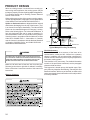
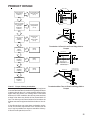
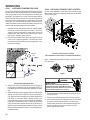
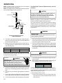
2. Connect a calibrated water manometer (or appropriate
gas pressure gauge) at either the gas valve inlet pressure tap or the gas piping drip leg as shown in the following figures. Refer to Measuring Gas Pressure: Single
Stage Valves figure for single stage valve inlet pressure
tap connections. Refer to Measuring Gas Pressure:
Two-Stage Valves figure for two-stage gas valve inlet
pressure tap connections.
53