1
Dear Custolller,
Congratulations on your purchase and welcome to the world's finest brand
of car audio. Through years of critical testing procedures and hand
craftsmanship. MA Audio has created a wide range of products that reproduce
music \,\Iith all the clarity and richness you deserve. The MA Audio
qll~·"'\I;t.,,··s '1"'" "('SPOI1S;I"'\I'~ ro '- nl'I~''''I'OlIS (JB
D·",n I IS J'--\
ACI & IdBL \l/
1
'\ ol "d
Records. This amplifier is more than capable of sending your subwoofers back
to the factory for repair, so please take caution when using this amplifier.
U
I. )
I 1 1\,.,1.....
(. 1 \,...
I '"' ~
• I V
\,..0
I
1
I I U
I I\,."
IUS ~
\J
I
For maximum performance we recommend you have your new MA
Audio product installed by an Authorized MA Audio Dealer. Please read
""U~
""'~~ant"
"",.J ~,,",,:n "" ...... ",,,,,,:,, .. " .. ,.J " •• : .. :",,1 ",,~fO" .',., .. ~OSS:J,I"
I
nOlI I · II J a l l u I \:"lalll JUUI I \:~\:IPl a l l u VI I b i l l a l ~al l
II lUI P
lUI\:"
JU
future use.
To learn more about MA Audio products and the current World Records held,
pleasc visit us at:
www.MaAudio.com
!! Attention !!
Continuous, exccssi ve exposure to sound pressure levels in excess of 85 dB
can cause a loss in hearing. While Ma Audio sound systems are capable of
producing sound pressure levels greater than 85dB.they are also designed for
enjoyment at reasonable levels. Please observe all local sound ordinances
while listening to your MA Audio sound system
TABLE OF CONTENTS
Features and Specifications
1
Control and Connection Locations
3
Control And Functions
4
Planning / Mounting Your System
5
Adjustment and Tuning
6
Wiring Diagram (2 CHANNEL)
7
Wiring Diagram ( Mono Block)
8
Wiring Diagram (4 CHANNEL)
9
Trouble Shooting Guide
10
Warranty
12
Warning
14
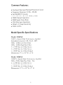
Common Features:
•
•
•
•
•
•
_
Overload, Short and Thennal Protection Circuit
Frequency Response: 20 Hz - 20 kHz
Full MOSFET Circuitry
Selectable Bass Boost 0-18dB @ 45Hz
50dB Channel Separation
90dB Signal Noise Ratio
'"' '"' T T
• LLl'\...
'"L
...
unrn
T ..
... L
...l
_
HlpUL llllVCUdl1CC
• 200mV-2V Input Sensitivity
• THD <0.05%
Model Specific Specifications
Model: M300XE
SO()W 2 channel High Pel/orl71ance Ampl{fier
Selectable Crossover: LPF, FLAT, HPF
50Hz - 250Hz Low Pass Filter
50Hz - 250Hz High Pass Filter
2 x 12S W Rms @ 4 Ohm Stereo
2 x 2S0WRms @ 2 Ohnl Stereo
I x SOOW Max @ 4 Ohm Bridged
Dimensions: 9" LxI 0" W x 2" H
Model: MSOOXE
1000W 4 channel High PeJ.j"orl1wnce AI71plifier
50Hz- 250Hz High Pass Filter / Flat
4 x 12SW Rms @ 4 Ohl11 Stereo
4 x 22SW Rl1ls @ 2 Ohm Stereo
2 x SOOW Max @ 4 Ohm Bridged
Dimensions: 13" Lx 10" W x 2" H
1
Model Specific Specifications Continued..
Model: M600XE
700W 2 channel High Performance Amplifier
Selectable Crossover: LPF, FLAT, HPF
50Hz - 250Hz Low Pass Filter
50Hz - 250Hz High Pass Filter
2 x J75W Rms @ 4 Ohm Stereo
2 x 350W Rms @ 2 Ohm Stereo
J x 700W Max @ 4 Ohm Bridged
Dimensions: 10.25" Lx 10" W x 2" H
Model: M700XE
JOOOW 2 channel High Performance Amplifier
50Hz - 250Hz Low Pass Filter
50Hz - 250Hz High Pass Filter
2 x 250W Rms @ 4 Ohm Stereo
2 x 500W Rms @ 2 Ohm Stereo
J x JOOOW Max @ 4 Ohm Bridged
Dimensions: 13" Lx 10" W x 2" H
Model: M1900XE
JOOOW Mono-Block High Performance Amplifier
50Hz - 250Hz Low Pass Filter
J x 500W Rms @ 4 Ohm Mono
J x JOOOW Max @ 2 Ohm Mono
Dimensions: 13" LxI 0" W x 2" H
2
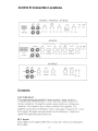
Control & Connection Locations
M300XE - M600XE - M700XE
X-OVER
PROT
HPF
..-(j'..
..
~
-.JIL
LPFFULLHPF
50Hz
HIGH INPUT
POWER
0
0
250Hz
M500XE
O@l@l[][] ICHQ.~\
~ '.-
;fIp.~.
:--
~o·
G
.~-~.
HIGH INPUT
X-OVER
0)'
3C~O·
. '.•
~...
@l@l@l@l@J~'
.
GAIN
2CH .
HPF
BS;~;T
GAIN
·0'··· '0'.'. '0'.'.
.-n
~.
,•
• •••
-.JIL
MIN
LPFFULLHPF 50Hz 250Hz
MAX
CH3i'
I
r--CH112~
LOWINPUT
••
MIN MAX OdS
X-OVER
I
LPF
·0···· 0
• .-n
~.
-.JIL
PROT POWER
18dS LPFFULLHPF 50Hz
•
0
.
250Hz
'CH
M1900XE
LOW
OUTPUT
LOW
INPUT
RCHO ORCH
~
LCH
o~o
LCH
GAIN
MODE
·:d:·
..
Q]
MIN
LPF
.
'd'
. ..
,
,
--l L-
50Hz 250Hz
LPF FULLHPF
MAX
PROT POW
Controls
Gain Adjustment:
This control adjusts the amplifier's input scnsitivity. Input sensitivity
is variable fi'om 100 Millivolts to 2 Volt. Turn the control clockwise to
inercase sensitivity. Turning the control counter-clockwise \vill decrease
sensitivity. This control is not a volume control for the amplifier. The
ampl ifier can be dri ven to full power with a wide rangc of signal levels. A low
level signal will require increased sensitivity for full power. A high level
signal will require dcereased sensitivity.
RCA Inputs:
These inputs arc for signal cables from a source unit. Always use high L]ulity
RCA cables.
3
Controls Continued...
Bass Boost Switch:
By using the bass boost function, bass notes at 50 Hz are amplified in
increments of OdB, 6dB and 12dB.
Crossover: Adjust the crossover for your chosen installation method.
- LPF: Low Pass Filter-only (50 Hz - 250 Hz)
- FLAT: No filtering for speakers. Use with full-range speakers.
- HPF: High pass filter (50 Hz - 250 Hz)
B- Terminal (Chassis ground):
To avoid unwanted ignition noise caused by ground loops, it is essential
that the amplifier be grounded to a clean, bare metal surface of the
vehicles chassis.
B+ Terminal (Battery positive):
Due to the power requirements of the Amplifier, this connection should
be made directly to the positive (+)terminal of the battery. For safety
measure, install an in-line fuse Holder (not included) as close to the
battery positive (+) terminal as possible with an ampere rating not to
exceed total value of fuses on the Amplifier.
Remote Turn-On Input:
Connect to remote turn-on wire of head unit. The amplifier is turned
"ON" remotely when the vehicle's head unit is turned "ON".
Variable Low-Pass Filter (50 Hz-250 Hz):
For use as a dedicated subwoofer channel. set filter switch to "LPF".
Adjust variable crossover frequency with control as desired. The
amplifier input circuit filters out everything above 50Hz to 250Hz
(dependent on the adjustment of the frequency control), so only the
deepest bass notes are amplified.
Variable High-Pass Filter (50 Hz-250 Hz):
For use as a dedicated mid-range channel, set filter switch to "HPF". The
circuit filters out all frequencies below 50 Hz to 250 Hz.
Power Indicator LEO:
This Blue LED will illuminate when the amplifier is turned "ON
4
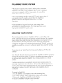
PLANNING YOUR SYSTEM
• If you plan to expand your system by adding other components
sometime in the future. ensure adequate space is left. If your head
unit/source is equipped with Pre-Amp outputs. it is possible to
utilize them to drive this Amplifier.
• Are your component speakers matched'! The peak power rating of
your speakers must be equal or greater than the Amplifier's.
Speakers connect to this ampli fier must have a I-X Ohm
impedance.
• Consider both the length of your leads, and routing when
determining the mounting location. Pre-Amp input Jacks require
high quality shielded RCA patch cords.
MOUNTING YOUR SYSTEM
The mounting position of your Amplifier will have a great effect 011 its
ability to dissipate the heat generated during normal operation. The Amplifier
has an efficient heat sink for proper heat dissipation. also integrated with a
thermal shutdown (for heat protection) circuit. Allowing air around the
cooling fins will improve heat dissipation dramatically. DO NOT enclose the
amplifier in a small box or cover it so that air cannot flow around the cooling
fins.
Temperatures in car trunks have been measured as high as
sum mer
(15~'
F) in the
time. Since the thermal shut-down point for the Amplifier is (160' F) it must be
mounted for maximum cooling. To achieve maximum convection air flow in
an enclosed trunk, mount the amplifier in a vertical position. on a vertical
surface.
Cooling requirements are considerably relaxed when mounting inside the
passenger compal1ment since the driver "viII not often allow temperatures to
reach a critical point. Floor mounting under the seat is usually satist~tctory as
long as there is at least 1 inch (2.54cm) above the Ampl itier's fins for
ventilation.
To mount the Amplifier:
I. Use the amplifier as a template to mark the mounting holes.
2. Use extreme caution, inspect underneath surface before drilling.
3. Remove the Amplifier an.d drill the marked holes.
4. Secure the Amplifier using the screws provided.
5
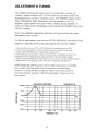
ADJUSTMENT & TUNING
The amplifier automatically turns on a few seconds after you turn your
vehicle's ignition switch to ACC or ON or turn on your auto sound system,
depending on how you have wired the system. The POWER indicator on the
side of the amplifier lights illuminates when the amplifier is on. Your
amplifier requires power from your vehicle's battery during operation. To
protect your battery from discharging, do not operate the amplifier unless your
vehicle is running.
Note: Your amplifier temporarily shuts down if it gets too hot, then restarts
automatically once it cools.
For the best performance, you must set LEVEL (MIN/MAX) on the side of the
amplifier to adjust the level of the audio signals that enter the amplifier.
1. Use a screwdriver to turn LEVEL (MIN/MAX) fully counterclockwise to MIN.
2. Turn the auto sound system's volume control to about one -third of its full range.
3. Adjust LEVEL (MIN/MAX) to a comfortable listening level.
4. Turn up the auto sound system's volume control until the sound begins to distort. Then
immediately turn the volume down to a point just before where the distortion began.
5. Adjust LEVEL (MIN/MAX) until the sound is at the level you want the amplifier to produce.
6. Adjust the auto sound systems volume control to a comfortable listening level.
NOTE Raising the LPFfrequency allows higherfrequencies to reach the
bass speakers while blocking lower frequencies.fi-om midrange
speakers. Lowering the Bass frequency allows lower frequencies to
reach the midrange speakers while blocking higherfrequenciesfrom
bass speakers.
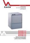
FREQUENCY RESPONSE
/ t"\.
+20dB
m
::2UJ
en
:z:
+10dB
OdB
0
0....
en
\.
/
-
BASS BOOST ON
/
\
V
~
-10dB
UJ
0:::
-20dB
-30dB
10
45
100
500
1K
FREQENCY (Hz)
6
5K
20K
50K
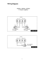
Wiring Diagram
M300XE, M600XE, M700XE
2 Channel Amplifiers
SPEAKER
e
LEFT
e
ffi
RIGHT
LEFT SPEAKER
2-8 OHM
e
RIGHT SPEAKER
2-8 OHM
STEREO MODE
SPEAKER
ffi
LEFT
e
ffi
RIGHT
e
@@
- - BRIDGED--
e
SUB WOOFER
8'---{ (~~ 4-8 OHM
1 . . . - -_ _
MONO MODE
7
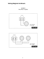
Wiring Diagram Continued...
M1900XE
Mono Block Amplifier
SPEAKER
e
EB
SUB WOOFER
2-4-8 OHM
MONO MODE
SPEAKER
L...-_,
+ -
+ -
---lL,
-----J1
SUB WOOFER
(2) - 4 OHM
MONO MODE
8
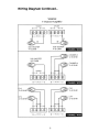
Wiring Diagram Continued...
M500XE
4 Channel Amplifier
SPEAKER
E!J
CH1
e
E!J
CH2
e
SPEAKER
E!J
CH3
e
E!J
CH4
e
SUB WOOFER
4-8 OHM
SUB WOOFER
4-8 OHM
2 CHANNEL MODE
CHANNEL 3
2-8 OHM
SUB WOOFER
4-8 OHM
CHANNEL4
2-8 OHM
E!J -
BRIDGED -
e
E!J -
BRIDGED -
e
3 CHANNEL MODE
CH 3
CH 3
2-8 OHM
2-8 OHM
CH 4
CH 4
2-8 OHM
2-8 OHM
E!J -
BRIDGED -
e
E!J -
9
BRIDGED -
e
4 CHANNEL MODE
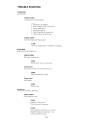
TROUBLE SHOOTING
SYMPTOM
NO SOUND.
CHECK POINT
Is the power LED illuminated?
CURE
I.
2.
J.
4.
Check fuses in amplifier.
Be sure Turn-on lead is connected.
Check signal leads.
Check gain control.
S. Check Tuner/Deck volume level.
6. Clean contacts on fuse holders.
CHECK POINT
Is the Overload LED illuminated?
CURE
Check for speaker short or ampldier overheating.
SYMPTOM
AMP NOT SWITCHING ON.
CHECK POINT
No power to power wire.
CURE
Repair power wire or connections.
Check point
No power to remote wire with Head Unit on.
CURE
Check connections to radio.
Check point
Fuse broken.
CURE
Replace Fuse.
SYMPTOM
NO SOUND IN ONE CHANNEL.
CHECK POINT
Check Speaker Leads.
CURE
Inspect for short circuit.
Check for open Connection.
CURE
Check Speaker Leads Reverse Left and
Right RCA inputs to determine if it is
occurring be fore the amp.
10
TROUBLE SHOOTING continued ...
SYMPTOM
AMP TURNING OFF AT MED/HIGH VOLUME.
CHECK POINT
Check Speaker load impedance.
CURE
Inspect that speaker load Impedance recommendations are
followed. Check wiring configuration for speakers.(To Verify
proper load impedance, use an OHM meter to measure the total
load for each channel of the amplifier.
SYMPTOM
SYSTEM PROTECTION LED IS LIT
CHECK POINT
Temperature Shut-down.
CURE
Check for proper air ventilation
Change amplifier location
CHECK POINT
output shorted.
CURE
Check speaker wiring
Check for blown speaker by disconnecting
one at a time and check for LED change.
??Need More Technical Support??
Please Visit The Technical Support Page at:
www.MaAudio.com
11
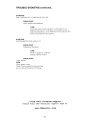
LIMITED WARRANTY INFORMATION
• LEngth of Warranty
I year on Video Products 2 years on Electronic Products 2 years on
Spe~lkers
• What is COVErEd
WJITC1nty applies only to 1\1;\ Audio products sold to consumers by Autl1llrized 1\1;\ Audio
Dcalers Ji1 the UnIted States of America or its possessions. Products purchased by consumers
from Authorized 1'.1A Audil) Deaier outside of the USA are covered only by that country's
distributor.
• Who is COVErEd
This warranty covers only the original purchaser or M!\ i\udio product purchased from an
Authorized 1\1;\ Audio De~l!er in the United States. For a list of AuthoJ'lzed Internet Retail Stores
go to http:/\vww.l\vIaAudio.com. In order to receive service. the purchaser must proVide MA
Audi(l with a copy of the r~'ceipt stating the customer name. MA Audio Authorized dealer name,
product purchased and date of purchase. Products found to be delcctive during the warranty
period will be rqxlII'ed or replaced (with C1 product deemed to be equivalent) at rvlA Audio's
discret ion.
• What is Not (OVErEd
J.
2.
:\.
4.
5.
6.
Damag~' caused by accident, abuse. improper operations. water, or theft.
Any co,t or expense related to the removal or reinstallation of product.
Repair Servicc performcd by anyone other than 1'.1A Audio's Repair Department.
Any product which has had the serial number det'aced. altered, or removed.
Any product purchascd outside the United States.
Any product not purchased from an Authorized 1'.1A Audio Dealer.
• limit on ImpliEd WarrantiES
An)' implied warranties IIlcluding warranties of fitness fill' usc and merchantability arc limited
in duration to the period of the c"press walTanty set fonh abovc. Some stales do not ililow
limitations onlhe length of an implied warranty, so this limitation may not apply. No person is
authorized to assumc for 1'.1A AudiO any other liability in conncctlon with the sale of the product.
• How to Obtain SErvice
I. Please call (310) 223-0400 for MA Audio Customer Service.
Customer Service hours: Monday-Friday. 8am-5pm Pacific Standard Time.
2. Obtain an RA +1 (Rctull1 Authorization Number) Ii'om Customer Service.
3. Obtain a "Cashiers Check" or "Money Order" for $lJ.OO pCI' item for return postage.
(No personal Cheeks will be accepted)
4. Once you receivc your return authorization number hom our Warranty Departll1l:nt.
please Pl'lnt thiS number LAnGE 011 the outside ufthe packaging.
5. No products will be accepted without a Return Authol'l7.ation nUll1ber.
6. Please include the followlIlg items wi th the returned product:
a. Copy of the Original Receipt of purchase (Required)
b. Cashiers Check or Money Order fur S1500 per item
e. Return Address for shipment.
7. Ship to:
1\1A Audio
Warranty Department
18601 South Susana noad
nancho Dominguez, CA 90221
RA#:
_
12
notes
13
WARNING
Investigate the layout of your automobile thoroughly before drilling or cutting any
holes. Use extreme care when you work ncar the gas tanks, gas or hydraulic lines.
and electrical wiring. Always make sure the power amplifier is securely mounted.
Mounting the amplifier securely to the automobile will prevent damage to the car or
injury to a person, pat1icularly in the event of an accident.
Don't mount the system so that the wire connections are unprotected or are subject
to pinching or damage from nearby objects.
The + 12 VDC pov:er wire must be fused at the battery positive terminal
connection. Before making or breaking power connections at the system power
terminals, disconnect the + 12V wire at the battery. Confirm your head unit and/or
other equipment is turned off v.:hile connecting the input RCA jacks and speaker
terminals.
If you need to replace the amplifier fuses, replace it only with a fusc identical to
that supplied with the systcm, Using a fuse of different type or rating may result in
damage to this system which isn't covered by the warranty.
14
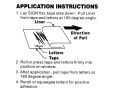
APPLICATION INSTRUCTIONS
1. Lay SIGN flat, tape side down. Pull Liner
from tape and letters at 180 degree angle.
Liner -----.
Direction
of Pull
Letters
Tape
2. Roll or press tape and letters firmly into
position on window~
3. After application, pull tape from letters at
180 degree angle.
4. Reroll or squeegee letters for positive
adhesion.
Stamp
~
N
N
o
'"•
•
N
Q)
::l
C\
l:
E
o
o
o
.s:
...l:
,~
•
"C
'o"
cr:
'l":
'"'::l"
VI
VI
~
N
'".....
~
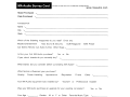
MA Audio Survey Card
Fill this out and send it in or suffer the consequences.
www.maaudio.com
Model Purchased '"
'----------------------------------,
Date Purchased
"'~
______,
Purchased From
Name "'~
___,
"'~
....,
City
State
"'~
___,
Which of the following magazines do you read? Circle any_
Mobile Entertainment
Auto Sound & Security
DUB Magazine
MAX Power
Car Stereo Review Car Audio & Elec Other Mags '"
~--------------------,
Is this your first MA Audio purchase?
Yes
If yes, which brands do you normally buy?
or
No
'"
'----------------------,
What brands did you consider before purchasing MA Audio? '"
~--------------,
What factors influenced your purchase?
Quality
Power Handling
Appearance
Your MA Audio equipment was installed by?
Friend
Reputation
Yourself
or
Other
Professional Installer
Was your MA Audio purchase an upgrade for your existing car stereo?
Your Age '"
~---'
Gender
M or
F or Other
'"~-----....,
Favorite Music Type
Yes
'"
or
No
~------....,
Fold and Tear Here ..
I stpm,
0000000000000.00
L
T
M
E
w
o
A
R
R
A
N
y
T
www.maaudio.com
What is Covered
Who is Covered
What is Not Covered
Warranty applies only
to MA Audio products
sold to consumers by
authorized MA Audio
dealers in the United
States of America or its
possessions. Products
purchased by consumers from authorized
MAAudio dealer outside
of the USA are covered
only by that country's
distributor.
This warranty covers only
the original purchaser of
MA Audio Inc. product
purchased from an authorized MA Audio dealer in
the United States. For a
list of authorized Internet
retail
stores
go
to
http://www.maaudio.com. In
order to receive service.
the purchaser must provide
MA Audio with a copy of the
receipt
stating
the
customer name, MA Audio
authorized dealer name,
product purchased and
date of purchase Products found to be defective
during the warranty period
mill be repaired or replaced
[with a product deemed to
be equivalent] at MA Audio's
discretion.
1> Damage caused by
accident, abuse, improper
operations, water or theft,
2> Any cost or expense
related to the removal or
reinstallation of product.
3> Repair service performed by anyone other
than MA Audio's repair
department.
4> Any product which has
had the serial number
defaced. altered or removed.
5> Any product purchased
outside the USA.
6> Any
product not
purchased from an authorized MA Audio dealer.
Limitll~~I~~~a~~:ranties
Any implied werrenties
including warranties of
fitness for use and
merchantability are limited in duration to the
period of the express
warranty set forth above.
Some states do not allow
limitations on the length
of an implied warranty, so
this limitation may not
apply.
No person is
authorized to assume for
MA Audio any other liability in connection with
the sale of the product.
Length of Warranty. 1 year on Video Products· 2 years on Electronic Products· 2 years on Speakers and Subwoofers
Your Records
Model Number
,'-
Date Purchased
Place of Purchase
---,
,'----------------------------------,
,'----------------------------------,
Fold and Tear Here .
This registration must be filled out and mailed within 10 days of purchase to validate warranty.
Name ,'Street
City
_,
,~------------------------------------,
,~
Model Number
Place Purchased
Purchased For
__,
,~_ _--'-
___,
State
Zip
Date Purchased
,~
' ......
• [Circle One]
' ......
-,
...,
___,
Gift
Replacement Speakers
Competition Use
To Cause Mayhem
If replacement, what is the name and model number of the system replaced?
Name
---,
,~
Model Number ,~
Why did you purchase MA Audio speakers?
Other
, ......
--,
•
[Circle One]
Sound
Price
Dealer Recommendation
--,