1
AXD - AXL - AXS - AXS12 - AXS6 - Aastra 5000 Server
Installation and Maintenance Manual
AMT/PTD/PBX/0058/4/6/EN
01/2011
Installation and Maintenance Manual - Aastra 5000
01/2011
AMT/PTD/PBX/0058/4/6/EN
Page 1
AASTRA
1 rue Arnold Schoenberg
78280 Guyancourt - France
Tel: +33 1 30 96 42 00
Fax: +33 1 30 96 43 00
www.aastra.com
Copyright © AASTRA
AMT/PTD/PBX/0058/4/6/ENInstallation and Maintenance Manual - Aastra 5000
Page 2
01/2011
Préliminaires
1
2
INTRODUCTION . . . . . . . . . . . . . . . . . . . . . . . . . . . . . . . . . . . . . . . . . . . . . . . .
27
1.1
PURPOSE OF THIS DOCUMENT . . . . . . . . . . . . . . . . . . . . . . . . . . . . . . . . . . .
27
1.2
TARGET AUDIENCE FOR THE DOCUMENT . . . . . . . . . . . . . . . . . . . . . . . . . .
28
1.3
REFERENCE DOCUMENTS . . . . . . . . . . . . . . . . . . . . . . . . . . . . . . . . . . . . . . .
29
1.4
ABBREVIATIONS . . . . . . . . . . . . . . . . . . . . . . . . . . . . . . . . . . . . . . . . . . . . . . . .
30
1.5
TERMS AND EXPRESSIONS. . . . . . . . . . . . . . . . . . . . . . . . . . . . . . . . . . . . . . .
31
1.6
DEFINITION . . . . . . . . . . . . . . . . . . . . . . . . . . . . . . . . . . . . . . . . . . . . . . . . . . . .
31
PRESENTATION. . . . . . . . . . . . . . . . . . . . . . . . . . . . . . . . . . . . . . . . . . . . . . . .
37
2.1
PRESENTATION OF AASTRA X SERIES PRODUCTS. . . . . . . . . . . . . . . . . . .
37
2.2
FUNCTIONAL AND PHYSICAL ARCHITECTURE OF THE IPBXS . . . . . . . . . .
39
2.2.1
Aastra XD . . . . . . . . . . . . . . . . . . . . . . . . . . . . . . . . . . . . . . . . . . . . . . . . . . .
39
2.2.2
Aastra XS/XL . . . . . . . . . . . . . . . . . . . . . . . . . . . . . . . . . . . . . . . . . . . . . . . .
40
OVERVIEW OF THE FUNCTIONS . . . . . . . . . . . . . . . . . . . . . . . . . . . . . . . . . . .
41
DESCRIPTION ET CARACTÉRISTIQUES D’UN PBX . . . . . . . . . . . . . . . . . .
43
3.1
PHYSICAL DESCRIPTION . . . . . . . . . . . . . . . . . . . . . . . . . . . . . . . . . . . . . . . . .
43
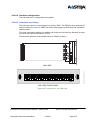
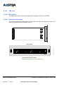
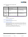
3.1.1 General description of AXD iPBXs . . . . . . . . . . . . . . . . . . . . . . . . . . . . . . . .
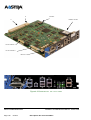
3.1.1.1 Internal description . . . . . . . . . . . . . . . . . . . . . . . . . . . . . . . . . . . . . . . .
43
44
3.1.2
General description of AXL iPBXs . . . . . . . . . . . . . . . . . . . . . . . . . . . . . . . .
55
3.1.3
General description of AXS iPBXs . . . . . . . . . . . . . . . . . . . . . . . . . . . . . . . .
60
3.1.4
Internal description . . . . . . . . . . . . . . . . . . . . . . . . . . . . . . . . . . . . . . . . . . . .
61
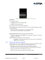
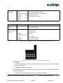
3.1.5 Physical description of an Aastra XS12 iPBX . . . . . . . . . . . . . . . . . . . . . . .
3.1.5.1 Control keys. . . . . . . . . . . . . . . . . . . . . . . . . . . . . . . . . . . . . . . . . . . . . .
3.1.5.2 Internal description . . . . . . . . . . . . . . . . . . . . . . . . . . . . . . . . . . . . . . . .
65
65
66
3.1.6 Physical description of an Aastra XS6 iPBX . . . . . . . . . . . . . . . . . . . . . . . .
3.1.6.1 Control keys. . . . . . . . . . . . . . . . . . . . . . . . . . . . . . . . . . . . . . . . . . . . . .
3.1.6.2 Internal description . . . . . . . . . . . . . . . . . . . . . . . . . . . . . . . . . . . . . . . .
69
69
70
2.3
3
3.2
CHARACTERISTICS. . . . . . . . . . . . . . . . . . . . . . . . . . . . . . . . . . . . . . . . . . . . . .
73
3.2.1
Physical specifications . . . . . . . . . . . . . . . . . . . . . . . . . . . . . . . . . . . . . . . . .
73
3.2.2
Electrical specifications . . . . . . . . . . . . . . . . . . . . . . . . . . . . . . . . . . . . . . . .
73
3.2.3
Environmental conditions . . . . . . . . . . . . . . . . . . . . . . . . . . . . . . . . . . . . . . .
75
3.3
CAPACITY. . . . . . . . . . . . . . . . . . . . . . . . . . . . . . . . . . . . . . . . . . . . . . . . . . . . . .
76
3.4
PHYSICAL BREAKDOWN . . . . . . . . . . . . . . . . . . . . . . . . . . . . . . . . . . . . . . . . .
77
3.4.1
Aastra XD . . . . . . . . . . . . . . . . . . . . . . . . . . . . . . . . . . . . . . . . . . . . . . . . . . .
77
3.4.2
Aastra XS/XL . . . . . . . . . . . . . . . . . . . . . . . . . . . . . . . . . . . . . . . . . . . . . . . .
82
CONFIGURATION RULES . . . . . . . . . . . . . . . . . . . . . . . . . . . . . . . . . . . . . . . . .
84
3.5
3.5.1
AXD iPBX . . . . . . . . . . . . . . . . . . . . . . . . . . . . . . . . . . . . . . . . . . . . . . . . . . .
Installation and Maintenance Manual - Aastra 5000
01/2011
AMT/PTD/PBX/0058/4/6/EN
Page 3
84
3.5.1.1 AXD main cabinet . . . . . . . . . . . . . . . . . . . . . . . . . . . . . . . . . . . . . . . . .
3.5.1.2 A2XD and A3XD expansion cabinet . . . . . . . . . . . . . . . . . . . . . . . . . . .
84
86
3.5.2 AXL iPBX . . . . . . . . . . . . . . . . . . . . . . . . . . . . . . . . . . . . . . . . . . . . . . . . . . .
3.5.2.1 AXL main cabinet. . . . . . . . . . . . . . . . . . . . . . . . . . . . . . . . . . . . . . . . . .
3.5.2.2 A2XL and A3XL expansion cabinets . . . . . . . . . . . . . . . . . . . . . . . . . . .
87
87
90
3.5.3
AXS/AXS12/AXS6 iPBX. . . . . . . . . . . . . . . . . . . . . . . . . . . . . . . . . . . . . . . .
91
3.6
I-BUTTON DONGLE AND SOFTWARE LOCKING . . . . . . . . . . . . . . . . . . . . . .
92
3.7
AXS/AXL/AXD IPBX SOFTWARE KEY CODES. . . . . . . . . . . . . . . . . . . . . . . . .
92
3.8
FUNCTIONAL DESCRIPTION PLATE 9.1 TO PLATE 9.4) . . . . . . . . . . . . . . . .
93
3.8.1 Command and processing unit . . . . . . . . . . . . . . . . . . . . . . . . . . . . . . . . . .
3.8.1.1 Data and voice switching function . . . . . . . . . . . . . . . . . . . . . . . . . . . . .
3.8.1.2 Duplex and start logic function (Aastra XD only) . . . . . . . . . . . . . . . . . .
3.8.1.3 Signal processing function. . . . . . . . . . . . . . . . . . . . . . . . . . . . . . . . . . .
3.8.1.4 Voice mail server function . . . . . . . . . . . . . . . . . . . . . . . . . . . . . . . . . . .
3.8.1.5 Defence function . . . . . . . . . . . . . . . . . . . . . . . . . . . . . . . . . . . . . . . . . .
3.8.1.6 Command management function. . . . . . . . . . . . . . . . . . . . . . . . . . . . . .
3.8.1.7 Synchronisation function . . . . . . . . . . . . . . . . . . . . . . . . . . . . . . . . . . . .
93
93
94
94
95
95
95
95
3.8.2
Connection to the communication networks and terminals . . . . . . . . . . . . .
96
3.8.3
Duplication (Aastra XD) . . . . . . . . . . . . . . . . . . . . . . . . . . . . . . . . . . . . . . . .
97
3.8.4 Synchronisation chain (Plate 9.1) . . . . . . . . . . . . . . . . . . . . . . . . . . . . . . . .
3.8.4.1 Synchronisation of an isolated or master iPBX in a multi-site network .
3.8.4.2 Management of the master/slave mode (multisite network) . . . . . . . . .
3.8.4.3 Propagation of the synchronisations inside a multisite network
(Plate 9.4) . . . . . . . . . . . . . . . . . . . . . . . . . . . . . . . . . . . . . . . . . . . . 102
100
100
101
3.8.5 Defence chain . . . . . . . . . . . . . . . . . . . . . . . . . . . . . . . . . . . . . . . . . . . . . . .
3.8.5.1 Overview . . . . . . . . . . . . . . . . . . . . . . . . . . . . . . . . . . . . . . . . . . . . . . . .
3.8.5.2 Monitoring . . . . . . . . . . . . . . . . . . . . . . . . . . . . . . . . . . . . . . . . . . . . . . .
3.8.5.3 Alarm management . . . . . . . . . . . . . . . . . . . . . . . . . . . . . . . . . . . . . . . .
3.8.5.4 Self protection . . . . . . . . . . . . . . . . . . . . . . . . . . . . . . . . . . . . . . . . . . . .
102
102
103
103
104
3.8.6 Power supply chain (figure 3.23) . . . . . . . . . . . . . . . . . . . . . . . . . . . . . . . . .
3.8.6.1 Aastra XD . . . . . . . . . . . . . . . . . . . . . . . . . . . . . . . . . . . . . . . . . . . . . . .
3.8.6.2 Aastra XS/XL . . . . . . . . . . . . . . . . . . . . . . . . . . . . . . . . . . . . . . . . . . . . .
104
104
108
3.8.7 Internal monitoring of AXS/AXL/AXD . . . . . . . . . . . . . . . . . . . . . . . . . . . . . .
3.8.7.1 Battery . . . . . . . . . . . . . . . . . . . . . . . . . . . . . . . . . . . . . . . . . . . . . . . . . .
3.8.7.2 Ventilation . . . . . . . . . . . . . . . . . . . . . . . . . . . . . . . . . . . . . . . . . . . . . . .
112
112
118
3.9
DIFFERENT CONFIGURATION OPTIONS . . . . . . . . . . . . . . . . . . . . . . . . . . . .
3.9.1
Configuration ex factory . . . . . . . . . . . . . . . . . . . . . . . . . . . . . . . . . . . . . . . .
118
3.9.2
Standard configuration . . . . . . . . . . . . . . . . . . . . . . . . . . . . . . . . . . . . . . . . .
119
3.9.3
Multi-company configuration . . . . . . . . . . . . . . . . . . . . . . . . . . . . . . . . . . . .
119
AMT/PTD/PBX/0058/4/6/EN
Page 4
118
01/2011
Installation and Maintenance Manual - Aastra 5000
4
3.9.4
Multi-site configuration . . . . . . . . . . . . . . . . . . . . . . . . . . . . . . . . . . . . . . . . .
119
3.9.5
Hotel/motel configuration . . . . . . . . . . . . . . . . . . . . . . . . . . . . . . . . . . . . . . .
119
3.9.6
Hospital configuration. . . . . . . . . . . . . . . . . . . . . . . . . . . . . . . . . . . . . . . . . .
119
3.10 THE USER INTERFACE . . . . . . . . . . . . . . . . . . . . . . . . . . . . . . . . . . . . . . . . . . .
120
DESCRIPTION DES SOUS-ENSEMBLES . . . . . . . . . . . . . . . . . . . . . . . . . . . .
121
4.1
121
EXPANSION CARDS . . . . . . . . . . . . . . . . . . . . . . . . . . . . . . . . . . . . . . . . . . . . .
4.1.1
DescriptionDescription des sous-ensembles . . . . . . . . . . . . . . . . . . . . . . . .
121
4.1.2
Loading CLX cards. . . . . . . . . . . . . . . . . . . . . . . . . . . . . . . . . . . . . . . . . . . .
123
POWER SUPPLY MODULE . . . . . . . . . . . . . . . . . . . . . . . . . . . . . . . . . . . . . . . .
124
4.2.1 ADS 350XD (AXD iPBX) . . . . . . . . . . . . . . . . . . . . . . . . . . . . . . . . . . . . . . .
4.2.1.1 Description. . . . . . . . . . . . . . . . . . . . . . . . . . . . . . . . . . . . . . . . . . . . . . .
4.2.1.2 Functional description . . . . . . . . . . . . . . . . . . . . . . . . . . . . . . . . . . . . . .
4.2.1.3 Monitoring . . . . . . . . . . . . . . . . . . . . . . . . . . . . . . . . . . . . . . . . . . . . . . .
4.2.1.4 Physical description . . . . . . . . . . . . . . . . . . . . . . . . . . . . . . . . . . . . . . . .
4.2.1.5 Hardware configuration . . . . . . . . . . . . . . . . . . . . . . . . . . . . . . . . . . . . .
4.2.1.6 Installation and wiring . . . . . . . . . . . . . . . . . . . . . . . . . . . . . . . . . . . . . .
124
124
124
125
125
126
126
4.2.2 ADS 300XD (AXD iPBX) . . . . . . . . . . . . . . . . . . . . . . . . . . . . . . . . . . . . . . .
4.2.2.1 Description. . . . . . . . . . . . . . . . . . . . . . . . . . . . . . . . . . . . . . . . . . . . . . .
4.2.2.2 Functional description (Figure 3.21 ) . . . . . . . . . . . . . . . . . . . . . . . . . . .
4.2.2.3 Monitoring . . . . . . . . . . . . . . . . . . . . . . . . . . . . . . . . . . . . . . . . . . . . . . .
4.2.2.4 Physical description (Figure 4.3 ) . . . . . . . . . . . . . . . . . . . . . . . . . . . . .
4.2.2.5 Hardware configuration . . . . . . . . . . . . . . . . . . . . . . . . . . . . . . . . . . . . .
4.2.2.6 Installation and wiring . . . . . . . . . . . . . . . . . . . . . . . . . . . . . . . . . . . . . .
127
127
127
128
129
129
130
4.2.3 ADS 350X (AXL iPBX) . . . . . . . . . . . . . . . . . . . . . . . . . . . . . . . . . . . . . . . . .
4.2.3.1 Description. . . . . . . . . . . . . . . . . . . . . . . . . . . . . . . . . . . . . . . . . . . . . . .
4.2.3.2 Functional description . . . . . . . . . . . . . . . . . . . . . . . . . . . . . . . . . . . . . .
4.2.3.3 Monitoring . . . . . . . . . . . . . . . . . . . . . . . . . . . . . . . . . . . . . . . . . . . . . . .
4.2.3.4 Physical description (Figure 4.5 ) . . . . . . . . . . . . . . . . . . . . . . . . . . . . .
4.2.3.5 Hardware configuration . . . . . . . . . . . . . . . . . . . . . . . . . . . . . . . . . . . . .
4.2.3.6 Installation and wiring . . . . . . . . . . . . . . . . . . . . . . . . . . . . . . . . . . . . . .
130
130
130
131
132
133
133
4.2.4 ADS 300X (AXL iPBX) . . . . . . . . . . . . . . . . . . . . . . . . . . . . . . . . . . . . . . . . .
4.2.4.1 Description. . . . . . . . . . . . . . . . . . . . . . . . . . . . . . . . . . . . . . . . . . . . . . .
4.2.4.2 Functional description (Figure 3.23 ) . . . . . . . . . . . . . . . . . . . . . . . . . . .
4.2.4.3 Monitoring . . . . . . . . . . . . . . . . . . . . . . . . . . . . . . . . . . . . . . . . . . . . . . .
4.2.4.4 Physical description (Figure 4.5 ) . . . . . . . . . . . . . . . . . . . . . . . . . . . . .
4.2.4.5 Hardware configuration . . . . . . . . . . . . . . . . . . . . . . . . . . . . . . . . . . . . .
4.2.4.6 Installation and wiring . . . . . . . . . . . . . . . . . . . . . . . . . . . . . . . . . . . . . .
134
134
134
135
136
137
137
4.2.5
138
4.2
ADS 150X (AXS and AXS12 iPBXs) . . . . . . . . . . . . . . . . . . . . . . . . . . . . . .
Installation and Maintenance Manual - Aastra 5000
01/2011
AMT/PTD/PBX/0058/4/6/EN
Page 5
4.2.5.1
4.2.5.2
4.2.5.3
4.2.5.4
4.2.5.5
4.2.5.6
4.3
Description. . . . . . . . . . . . . . . . . . . . . . . . . . . . . . . . . . . . . . . . . . . . . . .
Functional description . . . . . . . . . . . . . . . . . . . . . . . . . . . . . . . . . . . . . .
Monitoring . . . . . . . . . . . . . . . . . . . . . . . . . . . . . . . . . . . . . . . . . . . . . . .
Physical description . . . . . . . . . . . . . . . . . . . . . . . . . . . . . . . . . . . . . . . .
Hardware configuration . . . . . . . . . . . . . . . . . . . . . . . . . . . . . . . . . . . . .
Installation and wiring . . . . . . . . . . . . . . . . . . . . . . . . . . . . . . . . . . . . . .
138
138
138
138
139
139
UCV-D CARD . . . . . . . . . . . . . . . . . . . . . . . . . . . . . . . . . . . . . . . . . . . . . . . . . . .
140
4.3.1
Functional description . . . . . . . . . . . . . . . . . . . . . . . . . . . . . . . . . . . . . . . . .
140
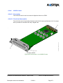
4.3.2 Physical description . . . . . . . . . . . . . . . . . . . . . . . . . . . . . . . . . . . . . . . . . . .
4.3.2.1 Indicators . . . . . . . . . . . . . . . . . . . . . . . . . . . . . . . . . . . . . . . . . . . . . . . .
143
145
4.3.3
Hardware and software configuration . . . . . . . . . . . . . . . . . . . . . . . . . . . . .
146
4.3.4
Installation and wiring. . . . . . . . . . . . . . . . . . . . . . . . . . . . . . . . . . . . . . . . . .
146
IUCV-D CARD . . . . . . . . . . . . . . . . . . . . . . . . . . . . . . . . . . . . . . . . . . . . . . . . . . .
148
4.4
4.4.1
Functional description . . . . . . . . . . . . . . . . . . . . . . . . . . . . . . . . . . . . . . . . .
148
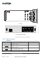
4.4.2 Physical description . . . . . . . . . . . . . . . . . . . . . . . . . . . . . . . . . . . . . . . . . . .
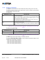
4.4.2.1 Connectors . . . . . . . . . . . . . . . . . . . . . . . . . . . . . . . . . . . . . . . . . . . . . .
4.4.2.2 Indicators . . . . . . . . . . . . . . . . . . . . . . . . . . . . . . . . . . . . . . . . . . . . . . . .
151
152
155
4.4.3
Hardware and software configuration . . . . . . . . . . . . . . . . . . . . . . . . . . . . .
156
4.4.4
Installation and wiring. . . . . . . . . . . . . . . . . . . . . . . . . . . . . . . . . . . . . . . . . .
156
RUCV-D CARD . . . . . . . . . . . . . . . . . . . . . . . . . . . . . . . . . . . . . . . . . . . . . . . . . .
157
4.5
4.5.1
Functional description . . . . . . . . . . . . . . . . . . . . . . . . . . . . . . . . . . . . . . . . .
157
4.5.2 Physical description . . . . . . . . . . . . . . . . . . . . . . . . . . . . . . . . . . . . . . . . . . .
4.5.2.1 Connectors . . . . . . . . . . . . . . . . . . . . . . . . . . . . . . . . . . . . . . . . . . . . . .
4.5.2.2 Indicators . . . . . . . . . . . . . . . . . . . . . . . . . . . . . . . . . . . . . . . . . . . . . . . .
157
157
157
4.5.3
Hardware and software configuration . . . . . . . . . . . . . . . . . . . . . . . . . . . . .
159
4.5.4 Installation and wiring. . . . . . . . . . . . . . . . . . . . . . . . . . . . . . . . . . . . . . . . . .
4.5.4.1 Connecting an expansion cabinet (A2XD). . . . . . . . . . . . . . . . . . . . . . .
4.5.4.2 Connecting two expansion cabinets (A3XD) . . . . . . . . . . . . . . . . . . . . .
159
160
161
4.6
UCV-L CARD. . . . . . . . . . . . . . . . . . . . . . . . . . . . . . . . . . . . . . . . . . . . . . . . . . . .
4.6.1
Functional description . . . . . . . . . . . . . . . . . . . . . . . . . . . . . . . . . . . . . . . . .
164
4.6.2 Physical description . . . . . . . . . . . . . . . . . . . . . . . . . . . . . . . . . . . . . . . . . . .
4.6.2.1 Connectors . . . . . . . . . . . . . . . . . . . . . . . . . . . . . . . . . . . . . . . . . . . . . .
4.6.2.2 Indicators . . . . . . . . . . . . . . . . . . . . . . . . . . . . . . . . . . . . . . . . . . . . . . . .
167
167
172
4.6.3
Hardware and software configuration . . . . . . . . . . . . . . . . . . . . . . . . . . . . .
173
4.6.4
Installation and wiring. . . . . . . . . . . . . . . . . . . . . . . . . . . . . . . . . . . . . . . . . .
174
UCV-S CARDS . . . . . . . . . . . . . . . . . . . . . . . . . . . . . . . . . . . . . . . . . . . . . . . . . .
175
4.7
4.7.1
Functional description . . . . . . . . . . . . . . . . . . . . . . . . . . . . . . . . . . . . . . . . .
175
4.7.2
Physical description . . . . . . . . . . . . . . . . . . . . . . . . . . . . . . . . . . . . . . . . . . .
177
AMT/PTD/PBX/0058/4/6/EN
Page 6
164
01/2011
Installation and Maintenance Manual - Aastra 5000
4.7.2.1 Connectors . . . . . . . . . . . . . . . . . . . . . . . . . . . . . . . . . . . . . . . . . . . . . .
4.7.2.2 Indicators . . . . . . . . . . . . . . . . . . . . . . . . . . . . . . . . . . . . . . . . . . . . . . . .
177
180
4.7.3
Hardware and software configuration. . . . . . . . . . . . . . . . . . . . . . . . . . . . . .
183
4.7.4
Installation and wiring. . . . . . . . . . . . . . . . . . . . . . . . . . . . . . . . . . . . . . . . . .
183
EXT1-S CARD . . . . . . . . . . . . . . . . . . . . . . . . . . . . . . . . . . . . . . . . . . . . . . . . . . .
184
4.8
4.8.1
Functional description . . . . . . . . . . . . . . . . . . . . . . . . . . . . . . . . . . . . . . . . .
184
4.8.2 Physical description . . . . . . . . . . . . . . . . . . . . . . . . . . . . . . . . . . . . . . . . . . .
4.8.2.1 Connectors . . . . . . . . . . . . . . . . . . . . . . . . . . . . . . . . . . . . . . . . . . . . . .
4.8.2.2 Indicators . . . . . . . . . . . . . . . . . . . . . . . . . . . . . . . . . . . . . . . . . . . . . . . .
186
186
187
4.8.3 Hardware and software configuration. . . . . . . . . . . . . . . . . . . . . . . . . . . . . .
4.8.3.1 Installation and wiring . . . . . . . . . . . . . . . . . . . . . . . . . . . . . . . . . . . . . .
187
188
4.8.4
Hardware and software configuration. . . . . . . . . . . . . . . . . . . . . . . . . . . . . .
190
4.8.5
Installation and wiring. . . . . . . . . . . . . . . . . . . . . . . . . . . . . . . . . . . . . . . . . .
190
EXT1-S12 CARD . . . . . . . . . . . . . . . . . . . . . . . . . . . . . . . . . . . . . . . . . . . . . . . . .
191
4.9
4.9.1
Functional description . . . . . . . . . . . . . . . . . . . . . . . . . . . . . . . . . . . . . . . . .
191
4.9.2 Physical description . . . . . . . . . . . . . . . . . . . . . . . . . . . . . . . . . . . . . . . . . . .
4.9.2.1 Connectors . . . . . . . . . . . . . . . . . . . . . . . . . . . . . . . . . . . . . . . . . . . . . .
4.9.2.2 Indicators . . . . . . . . . . . . . . . . . . . . . . . . . . . . . . . . . . . . . . . . . . . . . . . .
193
193
193
4.9.3 Hardware and software configuration. . . . . . . . . . . . . . . . . . . . . . . . . . . . . .
4.9.3.1 Installation and wiring . . . . . . . . . . . . . . . . . . . . . . . . . . . . . . . . . . . . . .
194
194
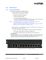
4.10 EXT1-S6 CARD . . . . . . . . . . . . . . . . . . . . . . . . . . . . . . . . . . . . . . . . . . . . . . . . . .
197
4.10.1 Functional description . . . . . . . . . . . . . . . . . . . . . . . . . . . . . . . . . . . . . . . . .
197
4.10.2 Physical description . . . . . . . . . . . . . . . . . . . . . . . . . . . . . . . . . . . . . . . . . . .
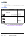
4.10.2.1 Connectors . . . . . . . . . . . . . . . . . . . . . . . . . . . . . . . . . . . . . . . . . . . . . .
4.10.2.2 Indicators . . . . . . . . . . . . . . . . . . . . . . . . . . . . . . . . . . . . . . . . . . . . . . . .
198
198
198
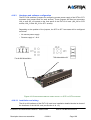
4.10.3 Hardware and software configuration. . . . . . . . . . . . . . . . . . . . . . . . . . . . . .
4.10.3.1 Installation and wiring . . . . . . . . . . . . . . . . . . . . . . . . . . . . . . . . . . . . . .
199
199
4.11 RUCV-L CARD . . . . . . . . . . . . . . . . . . . . . . . . . . . . . . . . . . . . . . . . . . . . . . . . . .
202
4.11.1 Functional description . . . . . . . . . . . . . . . . . . . . . . . . . . . . . . . . . . . . . . . . .
202
4.11.2 Physical description . . . . . . . . . . . . . . . . . . . . . . . . . . . . . . . . . . . . . . . . . . .
4.11.2.1 Connectors . . . . . . . . . . . . . . . . . . . . . . . . . . . . . . . . . . . . . . . . . . . . . .
4.11.2.2 Indicators . . . . . . . . . . . . . . . . . . . . . . . . . . . . . . . . . . . . . . . . . . . . . . . .
202
202
203
4.11.3 Hardware and software configuration. . . . . . . . . . . . . . . . . . . . . . . . . . . . . .
203
4.11.4 Installation and wiring. . . . . . . . . . . . . . . . . . . . . . . . . . . . . . . . . . . . . . . . . .
204
4.12 RUCV-S CARD . . . . . . . . . . . . . . . . . . . . . . . . . . . . . . . . . . . . . . . . . . . . . . . . . .
206
4.12.1 Functional description . . . . . . . . . . . . . . . . . . . . . . . . . . . . . . . . . . . . . . . . .
206
4.12.2 Physical description . . . . . . . . . . . . . . . . . . . . . . . . . . . . . . . . . . . . . . . . . . .
4.12.2.1 Connectors . . . . . . . . . . . . . . . . . . . . . . . . . . . . . . . . . . . . . . . . . . . . . .
206
206
Installation and Maintenance Manual - Aastra 5000
01/2011
AMT/PTD/PBX/0058/4/6/EN
Page 7
4.12.2.2 Indicators . . . . . . . . . . . . . . . . . . . . . . . . . . . . . . . . . . . . . . . . . . . . . . . .
206
4.12.3 Hardware and software configuration . . . . . . . . . . . . . . . . . . . . . . . . . . . . .
207
4.12.4 Installation and wiring. . . . . . . . . . . . . . . . . . . . . . . . . . . . . . . . . . . . . . . . . .
207
4.13 APPLICATION CARDS (CLX) . . . . . . . . . . . . . . . . . . . . . . . . . . . . . . . . . . . . . . .
209
4.13.1 LD4 card. . . . . . . . . . . . . . . . . . . . . . . . . . . . . . . . . . . . . . . . . . . . . . . . . . . .
4.13.1.1 Description. . . . . . . . . . . . . . . . . . . . . . . . . . . . . . . . . . . . . . . . . . . . . . .
4.13.1.2 Functional description . . . . . . . . . . . . . . . . . . . . . . . . . . . . . . . . . . . . . .
4.13.1.3 Physical description . . . . . . . . . . . . . . . . . . . . . . . . . . . . . . . . . . . . . . . .
209
209
209
210
4.13.2 Hardware configuration . . . . . . . . . . . . . . . . . . . . . . . . . . . . . . . . . . . . . . . .
4.13.2.1 Installation and wiring . . . . . . . . . . . . . . . . . . . . . . . . . . . . . . . . . . . . . .
4.13.2.2 Description of the signal processing daughter card: . . . . . . . . . . . . . . .
212
213
216
4.13.3 LD4NX card . . . . . . . . . . . . . . . . . . . . . . . . . . . . . . . . . . . . . . . . . . . . . . . . .
4.13.3.1 Description. . . . . . . . . . . . . . . . . . . . . . . . . . . . . . . . . . . . . . . . . . . . . . .
4.13.3.2 Functional description . . . . . . . . . . . . . . . . . . . . . . . . . . . . . . . . . . . . . .
4.13.3.3 Physical description . . . . . . . . . . . . . . . . . . . . . . . . . . . . . . . . . . . . . . . .
4.13.3.4 Hardware configuration . . . . . . . . . . . . . . . . . . . . . . . . . . . . . . . . . . . . .
4.13.3.5 Installation and wiring . . . . . . . . . . . . . . . . . . . . . . . . . . . . . . . . . . . . . .
217
217
217
220
223
224
4.13.4 LT2 card . . . . . . . . . . . . . . . . . . . . . . . . . . . . . . . . . . . . . . . . . . . . . . . . . . . .
4.13.4.1 Description. . . . . . . . . . . . . . . . . . . . . . . . . . . . . . . . . . . . . . . . . . . . . . .
4.13.4.2 Functional description (see Figure 4.35 ) . . . . . . . . . . . . . . . . . . . . . . .
4.13.4.3 Physical description (see Figure 4.37 ) . . . . . . . . . . . . . . . . . . . . . . . . .
4.13.4.4 Hardware configuration . . . . . . . . . . . . . . . . . . . . . . . . . . . . . . . . . . . . .
4.13.4.5 Installation and wiring . . . . . . . . . . . . . . . . . . . . . . . . . . . . . . . . . . . . . .
228
228
228
230
232
237
4.13.5 PT2 card. . . . . . . . . . . . . . . . . . . . . . . . . . . . . . . . . . . . . . . . . . . . . . . . . . . .
4.13.5.1 Overview . . . . . . . . . . . . . . . . . . . . . . . . . . . . . . . . . . . . . . . . . . . . . . . .
4.13.5.2 Functional description . . . . . . . . . . . . . . . . . . . . . . . . . . . . . . . . . . . . . .
4.13.5.3 Physical description (see Figure 4.44 ) . . . . . . . . . . . . . . . . . . . . . . . . .
4.13.5.4 Hardware configuration . . . . . . . . . . . . . . . . . . . . . . . . . . . . . . . . . . . . .
4.13.5.5 Installation and wiring . . . . . . . . . . . . . . . . . . . . . . . . . . . . . . . . . . . . . .
238
238
238
240
241
242
4.13.6 CS1 card . . . . . . . . . . . . . . . . . . . . . . . . . . . . . . . . . . . . . . . . . . . . . . . . . . .
4.13.6.1 Description. . . . . . . . . . . . . . . . . . . . . . . . . . . . . . . . . . . . . . . . . . . . . . .
4.13.6.2 Physical description . . . . . . . . . . . . . . . . . . . . . . . . . . . . . . . . . . . . . . . .
4.13.6.3 Connectors . . . . . . . . . . . . . . . . . . . . . . . . . . . . . . . . . . . . . . . . . . . . . .
4.13.6.4 Hardware configuration . . . . . . . . . . . . . . . . . . . . . . . . . . . . . . . . . . . . .
4.13.6.5 Installation and wiring . . . . . . . . . . . . . . . . . . . . . . . . . . . . . . . . . . . . . .
4.13.6.6 CA1 card . . . . . . . . . . . . . . . . . . . . . . . . . . . . . . . . . . . . . . . . . . . . . . . .
4.13.6.7 Description. . . . . . . . . . . . . . . . . . . . . . . . . . . . . . . . . . . . . . . . . . . . . . .
4.13.6.8 Physical description (see Figure 4.48 ) . . . . . . . . . . . . . . . . . . . . . . . . .
4.13.6.9 Hardware configuration . . . . . . . . . . . . . . . . . . . . . . . . . . . . . . . . . . . . .
243
243
245
245
246
247
249
249
250
252
AMT/PTD/PBX/0058/4/6/EN
Page 8
01/2011
Installation and Maintenance Manual - Aastra 5000
4.13.6.10Installation and wiring . . . . . . . . . . . . . . . . . . . . . . . . . . . . . . . . . . . . . .
252
4.13.7 CP1 card . . . . . . . . . . . . . . . . . . . . . . . . . . . . . . . . . . . . . . . . . . . . . . . . . . .
4.13.7.1 Description. . . . . . . . . . . . . . . . . . . . . . . . . . . . . . . . . . . . . . . . . . . . . . .
4.13.7.2 Physical description (see Figure 4.49 ) . . . . . . . . . . . . . . . . . . . . . . . . .
4.13.7.3 Hardware configuration . . . . . . . . . . . . . . . . . . . . . . . . . . . . . . . . . . . . .
4.13.7.4 Installation and wiring . . . . . . . . . . . . . . . . . . . . . . . . . . . . . . . . . . . . . .
254
254
255
255
255
4.13.8 MUM card. . . . . . . . . . . . . . . . . . . . . . . . . . . . . . . . . . . . . . . . . . . . . . . . . . .
4.13.8.1 Description. . . . . . . . . . . . . . . . . . . . . . . . . . . . . . . . . . . . . . . . . . . . . . .
4.13.8.2 Functional description . . . . . . . . . . . . . . . . . . . . . . . . . . . . . . . . . . . . . .
4.13.8.3 Physical description (see Figure 4.50 ) . . . . . . . . . . . . . . . . . . . . . . . . .
4.13.8.4 Hardware configuration . . . . . . . . . . . . . . . . . . . . . . . . . . . . . . . . . . . . .
4.13.8.5 Installation and wiring . . . . . . . . . . . . . . . . . . . . . . . . . . . . . . . . . . . . . .
256
256
256
258
259
259
4.14 EQUIPMENT CARDS . . . . . . . . . . . . . . . . . . . . . . . . . . . . . . . . . . . . . . . . . . . . .
260
4.14.1 LA16X card. . . . . . . . . . . . . . . . . . . . . . . . . . . . . . . . . . . . . . . . . . . . . . . . . .
4.14.1.1 Description. . . . . . . . . . . . . . . . . . . . . . . . . . . . . . . . . . . . . . . . . . . . . . .
4.14.1.2 Functional description . . . . . . . . . . . . . . . . . . . . . . . . . . . . . . . . . . . . . .
4.14.1.3 Physical description (see Figure 4.51 ) . . . . . . . . . . . . . . . . . . . . . . . . .
4.14.1.4 Hardware configuration . . . . . . . . . . . . . . . . . . . . . . . . . . . . . . . . . . . . .
4.14.1.5 Installation and wiring . . . . . . . . . . . . . . . . . . . . . . . . . . . . . . . . . . . . . .
260
260
260
262
262
262
4.14.2 LA16X-8 card . . . . . . . . . . . . . . . . . . . . . . . . . . . . . . . . . . . . . . . . . . . . . . .
4.14.2.1 Description. . . . . . . . . . . . . . . . . . . . . . . . . . . . . . . . . . . . . . . . . . . . . . .
4.14.2.2 Functional description . . . . . . . . . . . . . . . . . . . . . . . . . . . . . . . . . . . . . .
264
264
264
4.14.3 Physical description (see Figure 4.53 ) . . . . . . . . . . . . . . . . . . . . . . . . . . . .
4.14.3.1 Hardware configuration . . . . . . . . . . . . . . . . . . . . . . . . . . . . . . . . . . . . .
4.14.3.2 Installation and wiring . . . . . . . . . . . . . . . . . . . . . . . . . . . . . . . . . . . . . .
265
265
265
4.14.4 LA8 card . . . . . . . . . . . . . . . . . . . . . . . . . . . . . . . . . . . . . . . . . . . . . . . . . . .
4.14.4.1 Description. . . . . . . . . . . . . . . . . . . . . . . . . . . . . . . . . . . . . . . . . . . . . . .
4.14.4.2 Functional description . . . . . . . . . . . . . . . . . . . . . . . . . . . . . . . . . . . . . .
4.14.4.3 Physical description (see Figure 4.54 ) . . . . . . . . . . . . . . . . . . . . . . . . .
4.14.4.4 Hardware configuration . . . . . . . . . . . . . . . . . . . . . . . . . . . . . . . . . . . . .
4.14.4.5 Installation and wiring . . . . . . . . . . . . . . . . . . . . . . . . . . . . . . . . . . . . . .
266
266
266
267
267
267
4.14.5 LN16X card . . . . . . . . . . . . . . . . . . . . . . . . . . . . . . . . . . . . . . . . . . . . . . . . .
4.14.5.1 Description. . . . . . . . . . . . . . . . . . . . . . . . . . . . . . . . . . . . . . . . . . . . . . .
4.14.5.2 Functional description . . . . . . . . . . . . . . . . . . . . . . . . . . . . . . . . . . . . . .
4.14.5.3 Physical description (see Figure 4.55 ) . . . . . . . . . . . . . . . . . . . . . . . . .
4.14.5.4 Hardware configuration . . . . . . . . . . . . . . . . . . . . . . . . . . . . . . . . . . . . .
4.14.5.5 Installation and wiring . . . . . . . . . . . . . . . . . . . . . . . . . . . . . . . . . . . . . .
268
268
268
269
269
269
4.14.6 LN16X-8 card . . . . . . . . . . . . . . . . . . . . . . . . . . . . . . . . . . . . . . . . . . . . . . . .
4.14.6.1 Description. . . . . . . . . . . . . . . . . . . . . . . . . . . . . . . . . . . . . . . . . . . . . . .
271
271
Installation and Maintenance Manual - Aastra 5000
01/2011
AMT/PTD/PBX/0058/4/6/EN
Page 9
4.14.6.2 Functional description . . . . . . . . . . . . . . . . . . . . . . . . . . . . . . . . . . . . . .
271
4.14.7 Physical description (see Figure 4.56 ) . . . . . . . . . . . . . . . . . . . . . . . . . . . .
4.14.7.1 Hardware configuration . . . . . . . . . . . . . . . . . . . . . . . . . . . . . . . . . . . . .
4.14.7.2 Installation and wiring . . . . . . . . . . . . . . . . . . . . . . . . . . . . . . . . . . . . . .
272
272
272
4.14.8 LN8 card. . . . . . . . . . . . . . . . . . . . . . . . . . . . . . . . . . . . . . . . . . . . . . . . . . . .
4.14.8.1 Description. . . . . . . . . . . . . . . . . . . . . . . . . . . . . . . . . . . . . . . . . . . . . . .
4.14.8.2 Functional description . . . . . . . . . . . . . . . . . . . . . . . . . . . . . . . . . . . . . .
4.14.8.3 Physical description (see Figure 4.57 ) . . . . . . . . . . . . . . . . . . . . . . . . .
4.14.8.4 Hardware configuration . . . . . . . . . . . . . . . . . . . . . . . . . . . . . . . . . . . . .
4.14.8.5 Installation and wiring . . . . . . . . . . . . . . . . . . . . . . . . . . . . . . . . . . . . . .
274
274
274
274
275
275
4.14.9 LM8 card . . . . . . . . . . . . . . . . . . . . . . . . . . . . . . . . . . . . . . . . . . . . . . . . . . .
4.14.9.1 Description. . . . . . . . . . . . . . . . . . . . . . . . . . . . . . . . . . . . . . . . . . . . . . .
4.14.9.2 Functional description . . . . . . . . . . . . . . . . . . . . . . . . . . . . . . . . . . . . . .
4.14.9.3 Physical description (see Figure 4.58 ) . . . . . . . . . . . . . . . . . . . . . . . . .
4.14.9.4 Hardware configuration . . . . . . . . . . . . . . . . . . . . . . . . . . . . . . . . . . . . .
4.14.9.5 Installation and wiring . . . . . . . . . . . . . . . . . . . . . . . . . . . . . . . . . . . . . .
276
276
276
277
277
277
4.14.10LH8 card. . . . . . . . . . . . . . . . . . . . . . . . . . . . . . . . . . . . . . . . . . . . . . . . . . . .
4.14.10.1Description . . . . . . . . . . . . . . . . . . . . . . . . . . . . . . . . . . . . . . . . . . . . . .
4.14.10.2Functional description. . . . . . . . . . . . . . . . . . . . . . . . . . . . . . . . . . . . . .
4.14.10.3Physical description (see Figure 4.58 ) . . . . . . . . . . . . . . . . . . . . . . . .
4.14.10.4Installation and wiring . . . . . . . . . . . . . . . . . . . . . . . . . . . . . . . . . . . . . .
278
278
278
278
278
4.14.11LH16X card . . . . . . . . . . . . . . . . . . . . . . . . . . . . . . . . . . . . . . . . . . . . . . . . .
4.14.11.1Description . . . . . . . . . . . . . . . . . . . . . . . . . . . . . . . . . . . . . . . . . . . . . .
4.14.11.2Functional description. . . . . . . . . . . . . . . . . . . . . . . . . . . . . . . . . . . . . .
4.14.11.3Physical description (see Figure 4.51 ) . . . . . . . . . . . . . . . . . . . . . . . .
4.14.11.4Hardware configuration . . . . . . . . . . . . . . . . . . . . . . . . . . . . . . . . . . . .
4.14.11.5Installation and wiring . . . . . . . . . . . . . . . . . . . . . . . . . . . . . . . . . . . . . .
280
280
280
280
281
281
4.14.12LH16X-8 card . . . . . . . . . . . . . . . . . . . . . . . . . . . . . . . . . . . . . . . . . . . . . . . .
4.14.12.1Description . . . . . . . . . . . . . . . . . . . . . . . . . . . . . . . . . . . . . . . . . . . . . .
4.14.12.2Functional description. . . . . . . . . . . . . . . . . . . . . . . . . . . . . . . . . . . . . .
4.14.12.3Physical description (see Figure 4.53 ) . . . . . . . . . . . . . . . . . . . . . . . .
4.14.12.4Hardware configuration . . . . . . . . . . . . . . . . . . . . . . . . . . . . . . . . . . . .
4.14.12.5Installation and wiring . . . . . . . . . . . . . . . . . . . . . . . . . . . . . . . . . . . . . .
282
282
282
282
283
283
4.14.13LR4 card. . . . . . . . . . . . . . . . . . . . . . . . . . . . . . . . . . . . . . . . . . . . . . . . . . . .
4.14.13.1Description . . . . . . . . . . . . . . . . . . . . . . . . . . . . . . . . . . . . . . . . . . . . . .
4.14.13.2Functional description. . . . . . . . . . . . . . . . . . . . . . . . . . . . . . . . . . . . . .
4.14.13.3Physical description (see Figure 4.62 ) . . . . . . . . . . . . . . . . . . . . . . . .
4.14.13.4Hardware configuration . . . . . . . . . . . . . . . . . . . . . . . . . . . . . . . . . . . .
4.14.13.5Installation and wiring . . . . . . . . . . . . . . . . . . . . . . . . . . . . . . . . . . . . . .
284
284
284
286
287
288
4.14.14LI1 card . . . . . . . . . . . . . . . . . . . . . . . . . . . . . . . . . . . . . . . . . . . . . . . . . . . .
289
AMT/PTD/PBX/0058/4/6/EN
Page 10
01/2011
Installation and Maintenance Manual - Aastra 5000
5
4.14.14.1Description . . . . . . . . . . . . . . . . . . . . . . . . . . . . . . . . . . . . . . . . . . . . . .
4.14.14.2Functional description. . . . . . . . . . . . . . . . . . . . . . . . . . . . . . . . . . . . . .
4.14.14.3Physical description (see Figure 4.63 ). . . . . . . . . . . . . . . . . . . . . . . . .
4.14.14.4Hardware configuration. . . . . . . . . . . . . . . . . . . . . . . . . . . . . . . . . . . . .
4.14.14.5Installation and wiring . . . . . . . . . . . . . . . . . . . . . . . . . . . . . . . . . . . . . .
4.14.14.6Installing and wiring an LI1 card . . . . . . . . . . . . . . . . . . . . . . . . . . . . . .
289
289
292
293
294
294
4.14.15BTX card . . . . . . . . . . . . . . . . . . . . . . . . . . . . . . . . . . . . . . . . . . . . . . . . . . .
4.14.15.1Description . . . . . . . . . . . . . . . . . . . . . . . . . . . . . . . . . . . . . . . . . . . . . .
4.14.15.2Functional description. . . . . . . . . . . . . . . . . . . . . . . . . . . . . . . . . . . . . .
4.14.15.3Physical description (see Figure 4.50 ). . . . . . . . . . . . . . . . . . . . . . . . .
298
298
298
299
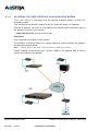
PRESENTATION OF PERIPHERAL DEVICES . . . . . . . . . . . . . . . . . . . . . . . .
301
5.1
301
5.1.1
Overview . . . . . . . . . . . . . . . . . . . . . . . . . . . . . . . . . . . . . . . . . . . . . . . . . . .
301
5.1.2
INSTALLATION . . . . . . . . . . . . . . . . . . . . . . . . . . . . . . . . . . . . . . . . . . . . . .
301
ANALOGUE SETS . . . . . . . . . . . . . . . . . . . . . . . . . . . . . . . . . . . . . . . . . . . . . . .
302
5.2
5.2.1
Description . . . . . . . . . . . . . . . . . . . . . . . . . . . . . . . . . . . . . . . . . . . . . . . . . .
302
5.2.2
INSTALLATION . . . . . . . . . . . . . . . . . . . . . . . . . . . . . . . . . . . . . . . . . . . . . .
302
IP SETS . . . . . . . . . . . . . . . . . . . . . . . . . . . . . . . . . . . . . . . . . . . . . . . . . . . . . . . .
303
5.3
5.3.1
Description . . . . . . . . . . . . . . . . . . . . . . . . . . . . . . . . . . . . . . . . . . . . . . . . . .
303
5.3.2
INSTALLATION . . . . . . . . . . . . . . . . . . . . . . . . . . . . . . . . . . . . . . . . . . . . . .
303
COMPUTER TERMINALS. . . . . . . . . . . . . . . . . . . . . . . . . . . . . . . . . . . . . . . . . .
304
5.4
5.4.1
Description . . . . . . . . . . . . . . . . . . . . . . . . . . . . . . . . . . . . . . . . . . . . . . . . . .
304
5.4.2
INSTALLATION . . . . . . . . . . . . . . . . . . . . . . . . . . . . . . . . . . . . . . . . . . . . . .
304
ATTENDANT CONSOLES (ATDC) . . . . . . . . . . . . . . . . . . . . . . . . . . . . . . . . . . .
305
5.5
5.5.1
Description . . . . . . . . . . . . . . . . . . . . . . . . . . . . . . . . . . . . . . . . . . . . . . . . . .
305
5.5.2
INSTALLATION . . . . . . . . . . . . . . . . . . . . . . . . . . . . . . . . . . . . . . . . . . . . . .
305
MISCELLANEOUS EQUIPMENT . . . . . . . . . . . . . . . . . . . . . . . . . . . . . . . . . . . .
306
5.6.1 External music source . . . . . . . . . . . . . . . . . . . . . . . . . . . . . . . . . . . . . . . . .
5.6.1.1 Description. . . . . . . . . . . . . . . . . . . . . . . . . . . . . . . . . . . . . . . . . . . . . . .
5.6.1.2 INSTALLATION . . . . . . . . . . . . . . . . . . . . . . . . . . . . . . . . . . . . . . . . . . .
306
306
306
5.6.2 Common bell . . . . . . . . . . . . . . . . . . . . . . . . . . . . . . . . . . . . . . . . . . . . . . . .
5.6.2.1 Overview . . . . . . . . . . . . . . . . . . . . . . . . . . . . . . . . . . . . . . . . . . . . . . . .
5.6.2.2 Installation . . . . . . . . . . . . . . . . . . . . . . . . . . . . . . . . . . . . . . . . . . . . . . .
306
306
307
5.6.3 Alarm bell . . . . . . . . . . . . . . . . . . . . . . . . . . . . . . . . . . . . . . . . . . . . . . . . . . .
5.6.3.1 Description. . . . . . . . . . . . . . . . . . . . . . . . . . . . . . . . . . . . . . . . . . . . . . .
5.6.3.2 Installation . . . . . . . . . . . . . . . . . . . . . . . . . . . . . . . . . . . . . . . . . . . . . . .
307
307
308
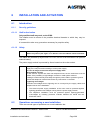
INSTALLATION AND ACTIVATION. . . . . . . . . . . . . . . . . . . . . . . . . . . . . . . . .
309
5.6
6
DIGITAL SETS . . . . . . . . . . . . . . . . . . . . . . . . . . . . . . . . . . . . . . . . . . . . . . . . . .
Installation and Maintenance Manual - Aastra 5000
01/2011
AMT/PTD/PBX/0058/4/6/EN
Page 11
6.1
INTRODUCTION . . . . . . . . . . . . . . . . . . . . . . . . . . . . . . . . . . . . . . . . . . . . . . . . .
309
6.1.1 Security guidelines . . . . . . . . . . . . . . . . . . . . . . . . . . . . . . . . . . . . . . . . . . . .
6.1.1.1 Staff authorisation . . . . . . . . . . . . . . . . . . . . . . . . . . . . . . . . . . . . . . . . .
6.1.1.2 Safety . . . . . . . . . . . . . . . . . . . . . . . . . . . . . . . . . . . . . . . . . . . . . . . . . .
309
309
309
6.2
OPERATIONS CONCERNING A NEW INSTALLATION . . . . . . . . . . . . . . . . . .
309
6.2.1 Preliminary operations . . . . . . . . . . . . . . . . . . . . . . . . . . . . . . . . . . . . . . . . .
6.2.1.1 Site inspection . . . . . . . . . . . . . . . . . . . . . . . . . . . . . . . . . . . . . . . . . . . .
6.2.1.2 Location . . . . . . . . . . . . . . . . . . . . . . . . . . . . . . . . . . . . . . . . . . . . . . . . .
6.2.1.3 Environment. . . . . . . . . . . . . . . . . . . . . . . . . . . . . . . . . . . . . . . . . . . . . .
6.2.1.4 Space. . . . . . . . . . . . . . . . . . . . . . . . . . . . . . . . . . . . . . . . . . . . . . . . . . .
6.2.1.5 Earth connection . . . . . . . . . . . . . . . . . . . . . . . . . . . . . . . . . . . . . . . . . .
6.2.1.6 Electrical power supply . . . . . . . . . . . . . . . . . . . . . . . . . . . . . . . . . . . . .
6.2.1.7 Equipment identification. . . . . . . . . . . . . . . . . . . . . . . . . . . . . . . . . . . . .
310
310
310
311
311
312
312
312
6.2.2
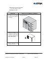
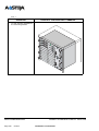
Installing an AXD cabinet . . . . . . . . . . . . . . . . . . . . . . . . . . . . . . . . . . . . . . .
314
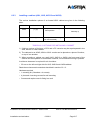
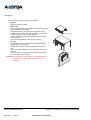
6.2.3
Installing a cabinet (AXL, AXS, AXS12 and AXS6) . . . . . . . . . . . . . . . . . . .
317
6.2.4 Wiring (AXD, AXL, AXS, AXS12 and AXS6) . . . . . . . . . . . . . . . . . . . . . . . .
6.2.4.1 Powering on the system . . . . . . . . . . . . . . . . . . . . . . . . . . . . . . . . . . . .
6.2.4.2 Viewing the status of the indicators located on the CPU card(s). . . . . .
319
320
320
6.2.5
320
Starting up a new system. . . . . . . . . . . . . . . . . . . . . . . . . . . . . . . . . . . . . . .
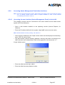
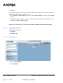
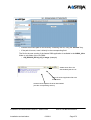
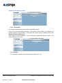
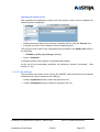
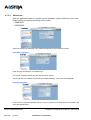
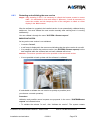
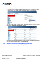
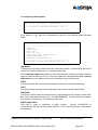
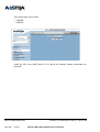
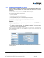
6.2.6 Accessing Aastra Management Portal (User interface). . . . . . . . . . . . . . . .
327
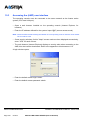
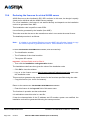
6.2.6.1 Accessing the user interface (Aastra Management Portal) via the LAN
327
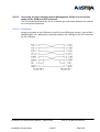
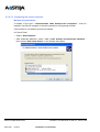
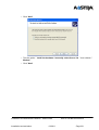
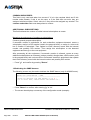
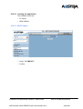
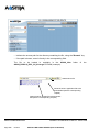
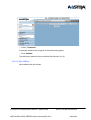
6.2.6.2 Accessing the user interface (Aastra Management Portal) in local access mode via
the COM port (PPP protocol). . . . . . . . . . . . . . . . . . . . . . . . . . . . . . 329
6.2.6.3 Backup remote access to AMP in SSH mode . . . . . . . . . . . . . . . . . . . .
337
6.2.7
Modifying the factory settings. . . . . . . . . . . . . . . . . . . . . . . . . . . . . . . . . . . .
339
6.2.8 Resetting the manufacturer's password (in case of loss). . . . . . . . . . . . . . .
6.2.8.1 Massive import from the massive creation form . . . . . . . . . . . . . . . . . .
6.2.8.2 Additional configurations . . . . . . . . . . . . . . . . . . . . . . . . . . . . . . . . . . . .
348
350
350
6.3
OPERATIONS ON A SITE ALREADY INSTALLED . . . . . . . . . . . . . . . . . . . . . .
6.3.1
Equipment checklist . . . . . . . . . . . . . . . . . . . . . . . . . . . . . . . . . . . . . . . . . . .
351
6.3.2
Handling cards . . . . . . . . . . . . . . . . . . . . . . . . . . . . . . . . . . . . . . . . . . . . . . .
352
6.3.3
Adding a CLX card (AXD, AXL, AXS, AXS12 and AXS6) . . . . . . . . . . . . . .
353
6.3.4
Adding an equipment card (AXD, AXL, AXS, AXS12 and AXS6) . . . . . . . .
355
6.3.5
Adding a daughter card on an expansion card (AXD, AXL, AXS, AXS12 and AXS6)
356
6.3.6 Adding EIP cards to an UCV CPU card . . . . . . . . . . . . . . . . . . . . . . . . . . . .
6.3.6.1 Adding EIP cards for AXD configuration . . . . . . . . . . . . . . . . . . . . . . . .
6.3.6.2 Adding EIP card(s) for AXL, AXS, AXS12 and AXS6 configuration . . .
357
359
361
6.3.7
362
Adding an expansion cabinet . . . . . . . . . . . . . . . . . . . . . . . . . . . . . . . . . . . .
AMT/PTD/PBX/0058/4/6/EN
Page 12
351
01/2011
Installation and Maintenance Manual - Aastra 5000
6.3.7.1 Adding an expansion cabinet (AXD) . . . . . . . . . . . . . . . . . . . . . . . . . . .
6.3.7.2 Adding an expansion cabinet (AXL) . . . . . . . . . . . . . . . . . . . . . . . . . . .
6.3.7.3 Adding an AXS, AXS12 and AXS6 expansion cabinet . . . . . . . . . . . . .
362
363
363
6.3.8 Adding an AXD power module . . . . . . . . . . . . . . . . . . . . . . . . . . . . . . . . . . .
6.3.8.1 ADS350XD and ADS300XD compatibility . . . . . . . . . . . . . . . . . . . . . . .
6.3.8.2 Cabinet fitted with ADS300XD module . . . . . . . . . . . . . . . . . . . . . . . . .
365
365
365
6.3.9
Changing to DUPLEX configuration for AXD . . . . . . . . . . . . . . . . . . . . . . . .
367
6.4
STOPPING THE SYSTEM (AXD, AXL, AXS, AXS12 AND AXS6) . . . . . . . . . . .
369
6.5
STOPPING THE SYSTEM (AXD, AXL, AXS, AXS12 AND AXS6) . . . . . . . . . . .
369
6.6
VIEWING THE IP ADDRESS IN CASE OF LOSS (OFFLINE) . . . . . . . . . . . . . .
370
6.7
UPDATING THE SOFTWARE OF A SIMPLEX AASTRA SYSTEM R5.1 TO R5.2
371
6.7.1
Principle . . . . . . . . . . . . . . . . . . . . . . . . . . . . . . . . . . . . . . . . . . . . . . . . . . . .
371
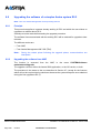
6.7.2 Upgrading the software from AMP . . . . . . . . . . . . . . . . . . . . . . . . . . . . . . . .
6.7.2.1 Loading update files. . . . . . . . . . . . . . . . . . . . . . . . . . . . . . . . . . . . . . . .
6.7.2.3 Switchover . . . . . . . . . . . . . . . . . . . . . . . . . . . . . . . . . . . . . . . . . . . . . . .
371
372
376
6.8
UPGRADING THE SOFTWARE OF A SIMPLEX AASTRA SYSTEM R5.2 . . . .
378
6.8.1
Principle . . . . . . . . . . . . . . . . . . . . . . . . . . . . . . . . . . . . . . . . . . . . . . . . . . . .
378
6.8.2
Upgrading the software from AMP . . . . . . . . . . . . . . . . . . . . . . . . . . . . . . . .
378
6.8.3
Restarting and validating the new version . . . . . . . . . . . . . . . . . . . . . . . . . .
379
6.8.4
Upgrading the software from Aastra Management AM 7450 . . . . . . . . . . . .
380
UPGRADING AN AXD IN DUPLEX CONFIGURATION MODE . . . . . . . . . . . . .
381
6.10 BACKING UP AND RESTORING THE CONFIGURATION . . . . . . . . . . . . . . . .
381
6.11 REMOTE ACCESS MODES . . . . . . . . . . . . . . . . . . . . . . . . . . . . . . . . . . . . . . . .
381
6.11.1 ACCESSING THE USER INTERFACE VIA AN ANALOGUE MODEM . . . .
382
6.11.2 ACCESSING THE USER INTERFACE (AMP) VIA AN ISDN MODEM . . . .
385
6.11.3 ACCESSING THE USER INTERFACE (AMP) VIA AN ISDN ROUTER . . .
6.11.3.1 CONNECTIONS . . . . . . . . . . . . . . . . . . . . . . . . . . . . . . . . . . . . . . . . . .
388
388
6.9
6.12 UPGRADING FROM A 1 GB COMPACT FLASH CARD TO A 2 GB COMPACT FLASH
CARD. . . . . . . . . . . . . . . . . . . . . . . . . . . . . . . . . . . . . . . . . . . . . . . . . . . . . . 389
7
6.12.1 Migration process . . . . . . . . . . . . . . . . . . . . . . . . . . . . . . . . . . . . . . . . . . . . .
6.12.1.1 Preliminary operations . . . . . . . . . . . . . . . . . . . . . . . . . . . . . . . . . . . . . .
6.12.1.2 Backing up data on the USB key (1 GB recommended) . . . . . . . . . . . .
6.12.1.3 Replacing the compact flash card . . . . . . . . . . . . . . . . . . . . . . . . . . . . .
6.12.1.4 Restart with the new 2 GB card in TOTAL mode, using Ctrl + i. . . . . . .
6.12.1.5 Restoring data from the USB key . . . . . . . . . . . . . . . . . . . . . . . . . . . . .
390
390
390
392
392
393
MAINTENANCE . . . . . . . . . . . . . . . . . . . . . . . . . . . . . . . . . . . . . . . . . . . . . . . .
395
7.1
395
SECURITY GUIDELINES . . . . . . . . . . . . . . . . . . . . . . . . . . . . . . . . . . . . . . . . . .
Installation and Maintenance Manual - Aastra 5000
01/2011
AMT/PTD/PBX/0058/4/6/EN
Page 13
7.2
MAINTENANCE OVERVIEW . . . . . . . . . . . . . . . . . . . . . . . . . . . . . . . . . . . . . . .
7.2.1
395
Role and possibilities available . . . . . . . . . . . . . . . . . . . . . . . . . . . . . . . . . .
395
7.2.2 Maintenance resources . . . . . . . . . . . . . . . . . . . . . . . . . . . . . . . . . . . . . . . .
7.2.2.1 Role of Aastra Management Portal (AMP) in maintenance . . . . . . . . . .
396
396
7.2.3
Preventive maintenance. . . . . . . . . . . . . . . . . . . . . . . . . . . . . . . . . . . . . . . .
397
7.2.4
Corrective maintenance . . . . . . . . . . . . . . . . . . . . . . . . . . . . . . . . . . . . . . . .
397
7.2.5
Restarting. . . . . . . . . . . . . . . . . . . . . . . . . . . . . . . . . . . . . . . . . . . . . . . . . . .
398
7.2.6
Returning subassemblies to be repaired . . . . . . . . . . . . . . . . . . . . . . . . . . .
398
7.2.7 List of interchangeable subassemblies, fuses, batteries, cables and securing kits 398
7.2.7.1 Interchangeable AXD iPBX subassemblies. . . . . . . . . . . . . . . . . . . . . .
399
7.2.7.2 Interchangeable AXS/AXL iPBX subassemblies . . . . . . . . . . . . . . . . . .
401
7.2.7.3 Interchangeable AXD/AXL/AXS/AXS12/AXS6 iPBX cables . . . . . . . . .
402
7.2.7.4 Interchangeable fuses . . . . . . . . . . . . . . . . . . . . . . . . . . . . . . . . . . . . . .
403
7.2.7.5 lithium batteries of UCV cards . . . . . . . . . . . . . . . . . . . . . . . . . . . . . . .
403
7.2.7.6 Optional interchangeable batteries . . . . . . . . . . . . . . . . . . . . . . . . . . . .
403
7.2.7.7 Interchangeable cabinets (AXD iPBX with ADS350XD) . . . . . . . . . . .
404
7.2.7.8 Interchangeable cabinets (AXL iPBX with ADS350 XL) . . . . . . . . . . . .
404
7.2.7.9 Mounting kits . . . . . . . . . . . . . . . . . . . . . . . . . . . . . . . . . . . . . . . . . . . . .
404
7.3
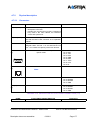
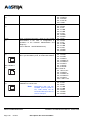
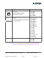
ALARM MESSAGES AND CODES. . . . . . . . . . . . . . . . . . . . . . . . . . . . . . . . . . .
7.3.1
Description of errors . . . . . . . . . . . . . . . . . . . . . . . . . . . . . . . . . . . . . . .
7.3.2
Operating system errors . . . . . . . . . . . . . . . . . . . . . . . . . . . . . . . . . . . .
405
405
405
7.3.3
Programming error codes . . . . . . . . . . . . . . . . . . . . . . . . . . . . . . . . . . . . . .
405
7.3.4
Additional error codes . . . . . . . . . . . . . . . . . . . . . . . . . . . . . . . . . . . . . . . . .
405
CORRECTIVE MAINTENANCE . . . . . . . . . . . . . . . . . . . . . . . . . . . . . . . . . . . . .
406
7.4.1 Description . . . . . . . . . . . . . . . . . . . . . . . . . . . . . . . . . . . . . . . . . . . . . . . . . .
7.4.1.1 Structure of exchange records. . . . . . . . . . . . . . . . . . . . . . . . . . . . . . . .
7.4.1.2 Conventions used in the sheets. . . . . . . . . . . . . . . . . . . . . . . . . . . . . . .
7.4.1.3 Guidelines . . . . . . . . . . . . . . . . . . . . . . . . . . . . . . . . . . . . . . . . . . . . . . .
406
406
408
408
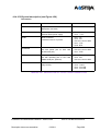
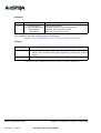
7.4.2
List of E sheets. . . . . . . . . . . . . . . . . . . . . . . . . . . . . . . . . . . . . . . . . . . . . . .
409
8
INSTALLING AND USING THE IPS CARD . . . . . . . . . . . . . . . . . . . . . . . . . . .
451
9
FUNCTIONAL DIAGRAMS . . . . . . . . . . . . . . . . . . . . . . . . . . . . . . . . . . . . . . . .
453
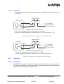
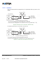
10 INSTALLING A5000 SERVER (NON-REDUNDANT) . . . . . . . . . . . . . . . . . . . .
459
10.1 IMPORTANT PRE-REQUISITE . . . . . . . . . . . . . . . . . . . . . . . . . . . . . . . . . . . . .
459
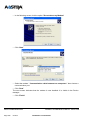
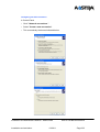
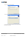
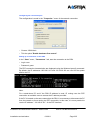
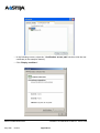
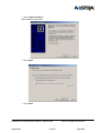
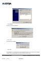
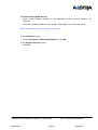
10.2 INSTALLING THE A5000 SERVER APPLICATION . . . . . . . . . . . . . . . . . . . . . .
459
10.3 ACCESSING THE (AMP) USER INTERFACE . . . . . . . . . . . . . . . . . . . . . . . . . .
470
10.4 DECLARING THE LICENCES FOR VIRTUAL A5000 SERVER. . . . . . . . . . . . .
472
7.4
AMT/PTD/PBX/0058/4/6/EN
Page 14
01/2011
Installation and Maintenance Manual - Aastra 5000
10.5 RESETTING THE MANUFACTURER'S PASSWORD (IN CASE OF LOSS) . . .
473
10.6 MASSIVE IMPORT FROM THE MASSIVE CREATION FORM . . . . . . . . . . . . .
475
10.7 ADDITIONAL CONFIGURATIONS . . . . . . . . . . . . . . . . . . . . . . . . . . . . . . . . . . .
476
10.7.1 Starting and viewing the services. . . . . . . . . . . . . . . . . . . . . . . . . . . . . . . . .
476
10.7.2 Declaring an NTP time server . . . . . . . . . . . . . . . . . . . . . . . . . . . . . . . . . . .
476
10.8 UPGRADING AASTRA 5000 SERVER SOFTWARE R5.1 TO R5.2 . . . . . . . . .
477
10.8.1 Principle . . . . . . . . . . . . . . . . . . . . . . . . . . . . . . . . . . . . . . . . . . . . . . . . . . . .
477
10.8.2 Upgrading Red Hat 5.4. . . . . . . . . . . . . . . . . . . . . . . . . . . . . . . . . . . . . . . . .
477
10.8.3 Checking the release of Red Hat Enterprise . . . . . . . . . . . . . . . . . . . . . . . .
478
10.8.4 Installing the A5000 Server R5.2 application . . . . . . . . . . . . . . . . . . . . . . . .
478
10.8.5 Restoring the R5.1 data . . . . . . . . . . . . . . . . . . . . . . . . . . . . . . . . . . . . . . . .
478
10.9 UPGRADING AASTRA 5000 SERVER R5.2 SOFTWARE. . . . . . . . . . . . . . . . .
479
10.9.1 Principle . . . . . . . . . . . . . . . . . . . . . . . . . . . . . . . . . . . . . . . . . . . . . . . . . . . .
479
10.9.2 Upgrading the software from AMP . . . . . . . . . . . . . . . . . . . . . . . . . . . . . . . .
10.9.2.1 Loading the application . . . . . . . . . . . . . . . . . . . . . . . . . . . . . . . . . . . . .
479
481
10.9.3 Switchover . . . . . . . . . . . . . . . . . . . . . . . . . . . . . . . . . . . . . . . . . . . . . . . . . .
484
10.9.4 Restarting and validating the new version . . . . . . . . . . . . . . . . . . . . . . . . . .
485
10.9.5 Via Aastra Management AM 7450 . . . . . . . . . . . . . . . . . . . . . . . . . . . . . . . .
486
10.10UPGRADING THE REDUNDANT A5000 SERVER . . . . . . . . . . . . . . . . . . . . . .
486
10.11BACKING UP AND RESTORING THE CONFIGURATION . . . . . . . . . . . . . . . .
486
11 APPENDICES . . . . . . . . . . . . . . . . . . . . . . . . . . . . . . . . . . . . . . . . . . . . . . . . . .
487
11.1 TAKING THE SECURITY CERTIFICATE INTO ACCOUNT . . . . . . . . . . . . . . . .
487
11.2 ACTIVATING/DEACTIVATING SELINUX IN RED HAT 5. . . . . . . . . . . . . . . . . .
492
11.3 CONFIGURING THE FIREWALL FOR ACS . . . . . . . . . . . . . . . . . . . . . . . . . . . .
493
11.4 USING THE MASSIVE CREATION FORM . . . . . . . . . . . . . . . . . . . . . . . . . . . . .
496
11.4.1 Considerations . . . . . . . . . . . . . . . . . . . . . . . . . . . . . . . . . . . . . . . . . . . . . . .
496
11.4.2 Introduction. . . . . . . . . . . . . . . . . . . . . . . . . . . . . . . . . . . . . . . . . . . . . . . . . .
496
11.4.3 Structure and content of the Excel form . . . . . . . . . . . . . . . . . . . . . . . . . . . .
11.4.3.1 Structure . . . . . . . . . . . . . . . . . . . . . . . . . . . . . . . . . . . . . . . . . . . . . . . .
11.4.3.2 Instructions for use . . . . . . . . . . . . . . . . . . . . . . . . . . . . . . . . . . . . . . . .
11.4.3.3 Backing up the file in .csv format . . . . . . . . . . . . . . . . . . . . . . . . . . . . . .
497
497
497
499
11.4.4 External record creation tab . . . . . . . . . . . . . . . . . . . . . . . . . . . . . . . . . . . . .
500
11.4.5 Selection keys tab . . . . . . . . . . . . . . . . . . . . . . . . . . . . . . . . . . . . . . . . . . . .
501
11.4.6 Multi-lines tab . . . . . . . . . . . . . . . . . . . . . . . . . . . . . . . . . . . . . . . . . . . . . . . .
502
Installation and Maintenance Manual - Aastra 5000
01/2011
AMT/PTD/PBX/0058/4/6/EN
Page 15
AMT/PTD/PBX/0058/4/6/EN
Page 16
01/2011
Installation and Maintenance Manual - Aastra 5000
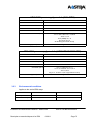
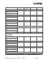
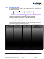
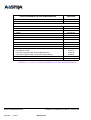
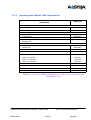
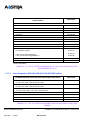
LIST OF TABLES
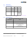
Table 3.1
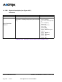
Physical characteristics of AXD, AXL, AXS, AXS12, and AXS6 PBXs . . . . . .
73
Tableau 3.2 List of AXD iPBX subassemblies . . . . . . . . . . . . . . . . . . . . . . . . . . . . . . . . .
82
Tableau 3.3 List of the sub-assemblies in AXL, AXS, AXS12 and AXS6 iPBXs. . . . . . . . .
83
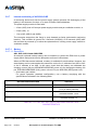
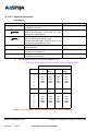
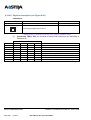
Tableau 3.4 Slot numbers on the backplane of an AXD iPBX . . . . . . . . . . . . . . . . . . . . . .
84
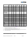
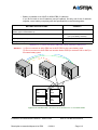
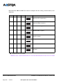
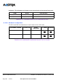
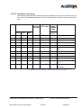
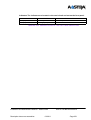
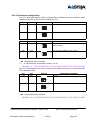
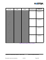
Tableau 3.5 Possible basic AXD iPBX back plane equipment configuration . . . . . . . . . . .
85
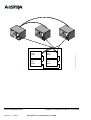
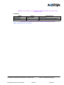
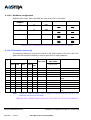
Tableau 3.6 Possible configurations of the two expansion backplanes of an AXD iPBX . .
86
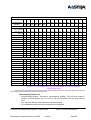
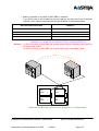
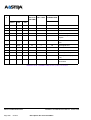
Tableau 3.7 Slot numbers on the backplane of an AXL iPBX. . . . . . . . . . . . . . . . . . . . . . .
87
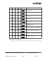
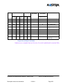
Tableau 3.8 Possible basic AXL iPBX back plane equipment configuration. . . . . . . . . . . .
88
Tableau 3.9 Possible configurations of the two expansion backplanes of an AXL iPBX . .
90
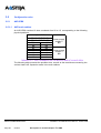
Tableau 3.10 Slot numbers on the backplane of an AXS/AXS12/AXS6 iPBX . . . . . . . . . . .
91
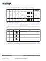
Tableau 3.11 Possible basic backplane and extension equipment configuration of an AXS/AXS12/
AXS6 iPBX . . . . . . . . . . . . . . . . . . . . . . . . . . . . . . . . . . . . . . . . . . . . . . . 91
Tableau 3.12 AXD, AXL, AXS, AXS12 and AXS6 iPBX battery characteristics . . . . . . . . . .
112
Tableau 3.13 A3XD or A3XL iPBX battery characteristics . . . . . . . . . . . . . . . . . . . . . . . . . .
113
Tableau 3.14 A2XD or AXL iPBX battery characteristics . . . . . . . . . . . . . . . . . . . . . . . . . . .
115
Tableau 3.15 Battery specifications for an A2XS iPBX. . . . . . . . . . . . . . . . . . . . . . . . . . . . .
117
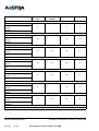
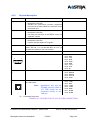
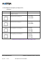
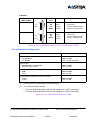
Tableau 4.1 Presentation of ADS 350XD power supply module indicators . . . . . . . . . . . .
126
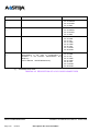
Tableau 4.2 Presentation of ADS 300XD power supply module indicators . . . . . . . . . . . .
129
Tableau 4.3 Presentation of ADS 350X power supply module indicators. . . . . . . . . . . . . .
133
Tableau 4.4 Presentation of ADS 300X power supply module indicators. . . . . . . . . . . . . .
137
Tableau 4.5 Description of UCV-D card connectors . . . . . . . . . . . . . . . . . . . . . . . . . . . . . .
143
Tableau 4.6 Overview of the UCV-D card indicators . . . . . . . . . . . . . . . . . . . . . . . . . . . . .
145
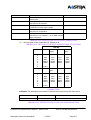
Tableau 4.7 DESCRIPTION OF IUCV-D CARD CONNECTOTRS (1/2) . . . . . . . . . . . . . .
152
Tableau 4.8 Description of IUCV-D card connectors (2/2) . . . . . . . . . . . . . . . . . . . . . . . . .
153
Tableau 4.9 Description of iUCV card relays . . . . . . . . . . . . . . . . . . . . . . . . . . . . . . . . . . .
154
Tableau 4.10 Presentation of IUCV-D card indicators . . . . . . . . . . . . . . . . . . . . . . . . . . . . .
155
Tableau 4.11 Description of RUCV-D card connectors. . . . . . . . . . . . . . . . . . . . . . . . . . . . .
157
Tableau 4.12 Overview of RUCV-D card indicators. . . . . . . . . . . . . . . . . . . . . . . . . . . . . . .
157
Tableau 4.13 Description of UCV-L card connectors (1/3) . . . . . . . . . . . . . . . . . . . . . . . . . .
167
Tableau 4.14 . . . . . . . . . . . . . . . . . . . . . . . . . Description of UCV-L card connectors (2/3)
168
Tableau 4.15 Description of UCV-L card connectors (3/3) . . . . . . . . . . . . . . . . . . . . . . . . . .
169
Tableau 4.16 Description of UCV card relays . . . . . . . . . . . . . . . . . . . . . . . . . . . . . . . . . . . .
170
Tableau 4.17 Presentation of UCV-L card indicators . . . . . . . . . . . . . . . . . . . . . . . . . . . . . .
172
Tableau 4.18 Description of UCV-S card connectors (1/3) . . . . . . . . . . . . . . . . . . . . . . . . . .
177
Tableau 4.19 Description of UCV-S card connectors (2/3) . . . . . . . . . . . . . . . . . . . . . . . . . .
178
Tableau 4.20 Description of UCV-S card connectors (3/3) . . . . . . . . . . . . . . . . . . . . . . . . . .
179
Tableau 4.21 Presentation of UCV-S card indicators (1/2) . . . . . . . . . . . . . . . . . . . . . . . . .
180
Tableau 4.22 Presentation of UCV-S card indicators (2/2) . . . . . . . . . . . . . . . . . . . . . . . . .
181
Tableau 4.23 Description of EXT1-S card connectors . . . . . . . . . . . . . . . . . . . . . . . . . . . . .
186
Tableau 4.24 S0 interface link with DECT base station (twisted cable) . . . . . . . . . . . . . . . .
189
Tableau 4.25 Description of EXT1-S12 card connectors . . . . . . . . . . . . . . . . . . . . . . . . . . .
193
Tableau 4.26 S0 interface link with DECT base station (twisted cable) . . . . . . . . . . . . . . . .
196
Tableau 4.27 Description of EXT1-S6 card connectors . . . . . . . . . . . . . . . . . . . . . . . . . . . .
198
Tableau 4.28 S0 interface link with DECT base station (twisted cable) . . . . . . . . . . . . . . . .
201
Tableau 4.29 Description of RUCV-L card connectors . . . . . . . . . . . . . . . . . . . . . . . . . . . . .
202
Tableau 4.30 Description of RUCV-L card INDICATORS. . . . . . . . . . . . . . . . . . . . . . . . . . .
203
Tableau 4.31 Description of RUCV-S card connectors . . . . . . . . . . . . . . . . . . . . . . . . . . . .
206
Tableau 4.32 Description of RUCV-S card INDICATORS . . . . . . . . . . . . . . . . . . . . . . . . . .
207
Tableau 4.33 Description of LD4 card connectors . . . . . . . . . . . . . . . . . . . . . . . . . . . . . . . .
211
Tableau 4.34 Details of the S0/T0 connections of LD4 card connectors . . . . . . . . . . . . . . .
211
Tableau 4.35 Presentation of the LD4 card indicators . . . . . . . . . . . . . . . . . . . . . . . . . . . . .
211
Tableau 4.36 Configuration of the CA2.1 microswitch on the lD4 card. . . . . . . . . . . . . . . . .
212
Tableau 4.37 Configuration of the CA2.2 microswitch on the LD4 card . . . . . . . . . . . . . . . .
212
Tableau 4.38 S0 interface link with DECT base station . . . . . . . . . . . . . . . . . . . . . . . . . . . .
215
Tableau 4.39 Description of LD4NX card connectors . . . . . . . . . . . . . . . . . . . . . . . . . . . . . .
220
Installation and Maintenance Manual - Aastra 5000
01/2011
AMT/PTD/PBX/0058/4/6/EN
Page 17
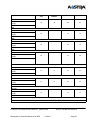
Tableau 4.40 Details of the S0/T0 connections of LD4NX card connectors . . . . . . . . . . . . .
Tableau 4.41 Presentation of LD4NX card indicators . . . . . . . . . . . . . . . . . . . . . . . . . . . . .
Tableau 4.42 Configuration of the microswitch CA1 (HVAL) on the LD4NX card . . . . . . . .
Tableau 4.43 . . . . . . . . . . . . . . . . . . . . . . . . . . . . . . . . . . . . . . . . . . . . . . . . . . . . . . . . . . . .
Tableau 4.44 S0 interface link with DECT base station . . . . . . . . . . . . . . . . . . . . . . . . . . . .
Tableau 4.45 Description of LT2 card connectors . . . . . . . . . . . . . . . . . . . . . . . . . . . . . . . .
Tableau 4.46 Presentation of LT2 card indicators . . . . . . . . . . . . . . . . . . . . . . . . . . . . . . . .
Tableau 4.47 Configuration of microswitch CA8 on the LT2 card (1/2) . . . . . . . . . . . . . . . .
Tableau 4.48 Configuration of the CA5 microswitch on the LT2 card. . . . . . . . . . . . . . . . . .
Tableau 4.49 Configuration of the CA7 microswitch on the LT2 card. . . . . . . . . . . . . . . . . .
Tableau 4.50 Configuration of the CA6, CA3 and CA2 microswitches on the LT2 card. . . .
Tableau 4.51 Configuration of the CA4 microswitch on the LT2 card. . . . . . . . . . . . . . . . . .
Tableau 4.52 Description of PT2 card connectors . . . . . . . . . . . . . . . . . . . . . . . . . . . . . . . .
Tableau 4.53 Presentation of the PT2 card indicators . . . . . . . . . . . . . . . . . . . . . . . . . . . . .
Tableau 4.54 Hardware configuration of the PT2 card . . . . . . . . . . . . . . . . . . . . . . . . . . . . .
Tableau 4.55 Description of CS1 card connectors . . . . . . . . . . . . . . . . . . . . . . . . . . . . . . . .
Tableau 4.56 Contacts of the synchronous connectors on the CS1 card. . . . . . . . . . . . . . .
Tableau 4.57 Presentation of CS1 card indicators . . . . . . . . . . . . . . . . . . . . . . . . . . . . . . . .
Tableau 4.58 Hardware configuration of the CS1 card. . . . . . . . . . . . . . . . . . . . . . . . . . . . .
Tableau 4.59 Connecting a DCE (CS1) to a DTE. . . . . . . . . . . . . . . . . . . . . . . . . . . . . . . . .
Tableau 4.60 Connecting a DTE (CS1) to a DCE. . . . . . . . . . . . . . . . . . . . . . . . . . . . . . . . .
Tableau 4.61 Description of CA1 card connectors . . . . . . . . . . . . . . . . . . . . . . . . . . . . . . . .
Tableau 4.62 Description of CA1 card connectors TE0 - Te3 . . . . . . . . . . . . . . . . . . . . . . .
Tableau 4.63 Presentation of the cA1 card indicators . . . . . . . . . . . . . . . . . . . . . . . . . . . . .
Tableau 4.64 Hardware configuration of the CA1 card. . . . . . . . . . . . . . . . . . . . . . . . . . . . .
Tableau 4.65 Connecting a DCE (CA1) to a DTE (PC or VT100 console) . . . . . . . . . . . . . .
Tableau 4.66 Connecting a DTE (CA1) to a DCE (modem or V24 adapter) . . . . . . . . . . . .
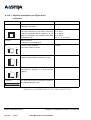
Tableau 4.67 Presentation of the CP1 card indicators . . . . . . . . . . . . . . . . . . . . . . . . . . . . .
Tableau 4.68 Description of MUM card connectors . . . . . . . . . . . . . . . . . . . . . . . . . . . . . . .
Tableau 4.69 Presentation of mum card indicators . . . . . . . . . . . . . . . . . . . . . . . . . . . . . . .
Tableau 4.70 Description of the LA16X card connectors . . . . . . . . . . . . . . . . . . . . . . . . . . .
Tableau 4.71 Description of LA16X-8 card connectors . . . . . . . . . . . . . . . . . . . . . . . . . . . .
Tableau 4.72 Description of LA8 card connectors . . . . . . . . . . . . . . . . . . . . . . . . . . . . . . . .
Tableau 4.73 Description of LN16x card connectors . . . . . . . . . . . . . . . . . . . . . . . . . . . . . .
Tableau 4.74 Description of LN16X-8 card connectors . . . . . . . . . . . . . . . . . . . . . . . . . . . .
Tableau 4.75 Description of the LN8 card connectors . . . . . . . . . . . . . . . . . . . . . . . . . . . . .
Tableau 4.76 description of the lm8 card connectors . . . . . . . . . . . . . . . . . . . . . . . . . . . . . .
Tableau 4.77 Description of LH16X card connectors . . . . . . . . . . . . . . . . . . . . . . . . . . . . . .
Tableau 4.78 Description of LH16X-8 card connectors . . . . . . . . . . . . . . . . . . . . . . . . . . . .
Tableau 4.79 description of the lr4 card connectors . . . . . . . . . . . . . . . . . . . . . . . . . . . . . . .
Tableau 4.80 Presentation of the lr4 card indicators . . . . . . . . . . . . . . . . . . . . . . . . . . . . . .
Tableau 4.81 configuration of the S1 microswitch on the LR4 card . . . . . . . . . . . . . . . . . . .
Tableau 4.82 configuration of the S2 microswitch on the LR4 card . . . . . . . . . . . . . . . . . . .
Tableau 4.83 Description of LI1 card connectors . . . . . . . . . . . . . . . . . . . . . . . . . . . . . . . . .
Tableau 4.84 Presentation of the li1 card indicators. . . . . . . . . . . . . . . . . . . . . . . . . . . . . . .
Tableau 4.85 configuring the LI1 card . . . . . . . . . . . . . . . . . . . . . . . . . . . . . . . . . . . . . . . . .
Tableau 4.86 Wiring the LI1 cable . . . . . . . . . . . . . . . . . . . . . . . . . . . . . . . . . . . . . . . . . . . .
Tableau 4.87 description of the BTX card connectors . . . . . . . . . . . . . . . . . . . . . . . . . . . . .
Tableau 4.88 Presentation of the BTX card indicators . . . . . . . . . . . . . . . . . . . . . . . . . . . . .
Tableau 4.89 Presentation of the BTX card jumpers . . . . . . . . . . . . . . . . . . . . . . . . . . . . . .
Tableau 6.1 Options for installing an AXD cabinet . . . . . . . . . . . . . . . . . . . . . . . . . . . . . . .
Tableau 6.2 Options for installing a cabinet . . . . . . . . . . . . . . . . . . . . . . . . . . . . . . . . . . . .
Tableau 7.1 List of interchangeable AXD iPBX subassemblies . . . . . . . . . . . . . . . . . . . .
Tableau 7.2 List of interchangeable AXL, AXS, AXS12, AXS6 iPBX sub-assemblies (1/2)
Tableau 7.3 List of interchangeable AXL, AXS, AXS12 and AXS6 iPBX sub-assemblies (2/2)
Tableau 7.4 List of interchangeable AXD/AXL/AXS/AXS12/AXS6 iPBX cables. . . . . . . . .
Tableau 7.5 List of interchangeable FUSES. . . . . . . . . . . . . . . . . . . . . . . . . . . . . . . . . . . .
Tableau 7.6 List of lithium batteries . . . . . . . . . . . . . . . . . . . . . . . . . . . . . . . . . . . . . . . . . .
AMT/PTD/PBX/0058/4/6/EN
Page 18
01/2011
221
221
223
227
227
230
231
232
234
235
236
236
240
241
241
245
245
246
246
247
248
250
250
251
252
252
253
255
258
259
262
265
267
269
272
274
277
281
283
286
286
287
287
292
293
293
295
299
300
300
314
317
400
401
402
402
403
403
Installation and Maintenance Manual - Aastra 5000
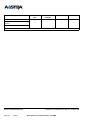
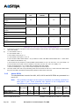
Tableau 7.7 List of optional interchangeable batteries . . . . . . . . . . . . . . . . . . . . . . . . . . . .
Tableau 7.8 List of interchangeable cabinets (AXD iPBX) . . . . . . . . . . . . . . . . . . . . . . . . .
Tableau 7.9 List of mounting kits . . . . . . . . . . . . . . . . . . . . . . . . . . . . . . . . . . . . . . . . . . . .
Tableau 7.10 List of E sheets . . . . . . . . . . . . . . . . . . . . . . . . . . . . . . . . . . . . . . . . . . . . . . . .
Installation and Maintenance Manual - Aastra 5000
01/2011
AMT/PTD/PBX/0058/4/6/EN
Page 19
403
404
404
409
AMT/PTD/PBX/0058/4/6/EN
Page 20
01/2011
Installation and Maintenance Manual - Aastra 5000
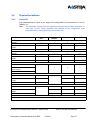
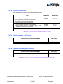
LIST OF PLATES
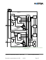
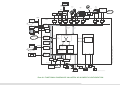
PLATE 9.1
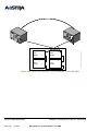
FUNCTIONAL DIAGRAM OF AN AASTRA XD IN SIMPLEX CONFIGURATION
455
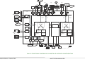
PLATE 9.2
FUNCTIONAL DIAGRAM OF AN AASTRA XD IN DUPLEX CONFIGURATION
456
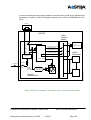
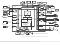
PLATE 9.3
FUNCTIONAL DIAGRAM OF AN AASTRA XL, XS AND XS12
457
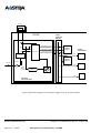
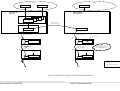
PLATE 9.4
PRINCIPLE OF MULTI-SITE SYNCHRONISATION
458
Installation and Maintenance Manual - Aastra 5000AMT/PTD/PBX/0058/4/6/EN
Préliminaires01/2011
Page 21
AMT/PTD/PBX/0058/4/6/EN
Page 22
01/2011
Installation and Maintenance Manual - Aastra 5000
LIST OF FIGURES
Figure 3.1
Figure 3.2
Figure 3.3
Figure 3.4
Figure 3.5
Figure 3.6
Figure 3.7
Figure 3.8
Figure 3.9
Figure 3.10
Figure 3.11
Figure 3.12
Figure 3.13
Figure 3.14
Figure 3.15
Figure 3.16
Figure 3.17
Figure 3.18
Figure 3.19
Figure 3.20
Figure 3.21
Figure 3.22
Figure 3.23
Figure 3.24
Figure 3.25
Figure 3.26
Figure 3.27
Figure 3.28
Figure 3.29
Figure 3.30
Figure 4.1
Figure 4.2
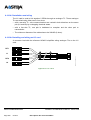
Figure 4.3
Figure 4.4
Figure 4.5
Figure 4.6
Figure 4.7
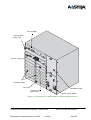
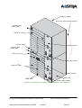
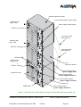
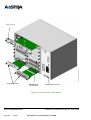
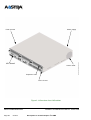
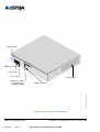
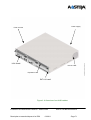
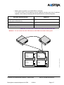
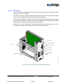
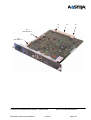
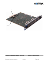
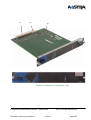
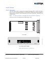
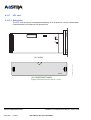
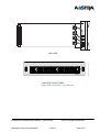
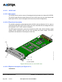
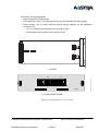
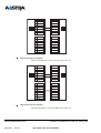
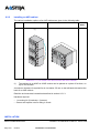
Overview of an AXD cabinet in simplex configuration. . . . . . . . . . . . . . . . . . .
45
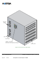
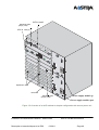
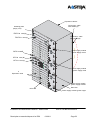
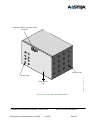
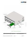
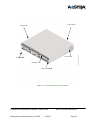
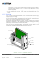
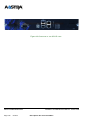
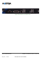
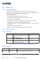
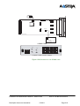
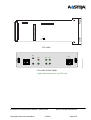
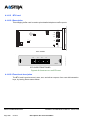
Rear view of an AXD cabinet . . . . . . . . . . . . . . . . . . . . . . . . . . . . . . . . . . . . .
46
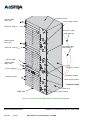
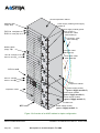
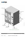
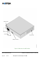
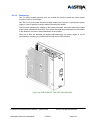
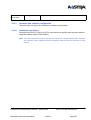
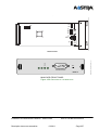
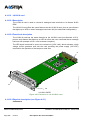
Overview of an A2XD cabinet in simplex configuration. . . . . . . . . . . . . . . . . .
47
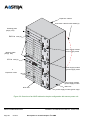
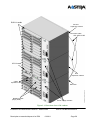
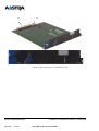
Overview of an A3XD cabinet in simplex configuration. . . . . . . . . . . . . . . . . .
48
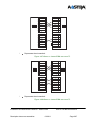
Overview of an AXD cabinet in simplex configuration with secure power unit
49
Overview of an A2XD cabinet in simplex configuration with secure power unit
50
Overview of an A3XD cabinet in simplex configuration with secure power unit
51
Overview of an AXD cabinet in duplex configuration . . . . . . . . . . . . . . . . . . .
52
Overview of an A3XD cabinet in duplex configuration . . . . . . . . . . . . . . . . . .
54
Overview of an AXL cabinet . . . . . . . . . . . . . . . . . . . . . . . . . . . . . . . . . . . . . .
56
Rear view of an AXL cabinet. . . . . . . . . . . . . . . . . . . . . . . . . . . . . . . . . . . . . .
57
Overview of an A2XL cabinet . . . . . . . . . . . . . . . . . . . . . . . . . . . . . . . . . . . . .
58
Overview of an A3XL cabinet . . . . . . . . . . . . . . . . . . . . . . . . . . . . . . . . . . . . .
59
Overview of an AXS cabinet . . . . . . . . . . . . . . . . . . . . . . . . . . . . . . . . . . . . . .
62
Overview of an A2XS cabinet . . . . . . . . . . . . . . . . . . . . . . . . . . . . . . . . . . . . .
63
Rear view of an AXS cabinet . . . . . . . . . . . . . . . . . . . . . . . . . . . . . . . . . . . . .
64
Overview of an AXS12 cabinet . . . . . . . . . . . . . . . . . . . . . . . . . . . . . . . . . . . .
67
Rear view of an AXS12 cabinet . . . . . . . . . . . . . . . . . . . . . . . . . . . . . . . . . . .
68
Overview of an AXS6 cabinet . . . . . . . . . . . . . . . . . . . . . . . . . . . . . . . . . . . . .
71
Rear view of an AXS6 cabinet . . . . . . . . . . . . . . . . . . . . . . . . . . . . . . . . . . . .
72
Block diagram of the power supply chain in an AXD cabinet
in simplex configuration. . . . . . . . . . . . . . . . . . . . . . . . . . . . . . . . . . . . . . . 106
Block diagram of the power supply chain in an AXD cabinet in duplex configuration.107
Block diagram of the power supply chain in an AXL cabinet . . . . . . . . . . . . .
109
Block diagram of the power supply chain in an AXS cabinet . . . . . . . . . . . . .
110
Block diagram of the power supply chain on an AXS12/AXS6 cabinet. . . . . .
111
Connecting a battery pack in parallel to an A3XD iPBX . . . . . . . . . . . . . . . . .
113
Connecting a battery pack in parallel to an A3XL iPBX . . . . . . . . . . . . . . . . .
114
Connecting a battery pack in parallel to an A2XD iPBX . . . . . . . . . . . . . . . . .
115
Connecting a battery pack in parallel to an A2XL iPBX . . . . . . . . . . . . . . . .
116
Connecting a battery pack in parallel to an A2XS iPBX . . . . . . . . . . . . . . . . .
117
Procedure for locking a card or blanking plate . . . . . . . . . . . . . . . . . . . . . . . .
122
Overview of the ADS350 XD module . . . . . . . . . . . . . . . . . . . . . . . . . . . . . . .
125
Overview of the ADS300 XD module . . . . . . . . . . . . . . . . . . . . . . . . . . . . . . .
128
OVERVIEW OF THE ADS 350X MODULE . . . . . . . . . . . . . . . . . . . . . . . . . .
131
OVERVIEW OF THE ADS 300X MODULE . . . . . . . . . . . . . . . . . . . . . . . . . .
135
Overview of the UCV-D card. . . . . . . . . . . . . . . . . . . . . . . . . . . . . . . . . . . . . .
142
IUCV-D interface between two UCV-D cards . . . . . . . . . . . . . . . . . . . . . . . . .
148
Installation and Maintenance Manual - Aastra 5000 AMT/PTD/PBX/0058/4/6/EN
Préliminaires01/2011
Page 1-23
Figure 4.8
Figure 4.9
Figure 4.10
Figure 4.11
Figure 4.12
Figure 4.13
Figure 4.14
Figure 4.15
Figure 4.16
Figure 4.17
Figure 4.18
Figure 4.19
Figure 4.20
Figure 4.21
Figure 4.22
Figure 4.23
Figure 4.24
Figure 4.25
Figure 4.26
Figure 4.27
Figure 4.28
Figure 4.29
Figure 4.30
Figure 4.31
Figure 4.32
Figure 4.33
Figure 4.34
Figure 4.35
Figure 4.36
Figure 4.37
Figure 4.38
Figure 4.39
Figure 4.40
Figure 4.41
Figure 4.42
Figure 4.43
Figure 4.44
Figure 4.45
Figure 4.46
Figure 4.47
Overview of the IUCV-D card . . . . . . . . . . . . . . . . . . . . . . . . . . . . . . . . . . . . .
150
iUCV card relay contacts . . . . . . . . . . . . . . . . . . . . . . . . . . . . . . . . . . . . . . . .
154
Presentation of IUCV-D card indicators . . . . . . . . . . . . . . . . . . . . . . . . . . . . .
155
Overview of the RUCV-D card . . . . . . . . . . . . . . . . . . . . . . . . . . . . . . . . . . . .
158
Colour code for connection to the expansion cabinet(s) . . . . . . . . . . . . . . . .
159
Connecting an expansion cabinet (simplex configuration, UCV-D(A)/RUCV-D(A)) 160
Connecting an expansion cabinet (simplex configuration, UCV-D(B)-RUCV-D(B)) 160
Connecting an expansion cabinet (duplex configuration) . . . . . . . . . . . . . . . .
161
Connecting two expansion cabinets (simplex configuration, UCV-D(A)/RUCV-D(A))161
Connecting two expansion cabinets (simplex configuration, UCT-D(B)-RUCT-D(B))162
Connecting two expansion cabinets (duplex configuration) . . . . . . . . . . . . . .
163
Overview of the UCV-L card . . . . . . . . . . . . . . . . . . . . . . . . . . . . . . . . . . . . . .
166
UCV CARD RELAY CONTACTS . . . . . . . . . . . . . . . . . . . . . . . . . . . . . . . . . .
171
Presentation of UCV-L card indicators . . . . . . . . . . . . . . . . . . . . . . . . . . . . . .
173
Overview of the ucv-s card . . . . . . . . . . . . . . . . . . . . . . . . . . . . . . . . . . . . . .
176
Presentation of UCV-S card indicators . . . . . . . . . . . . . . . . . . . . . . . . . . . . .
181
Overview of the EXT1-S card . . . . . . . . . . . . . . . . . . . . . . . . . . . . . . . . . . . . .
185
Configuring remote power supply of S/T0 to S/T3 accesses . . . . . . . . . . . . .
187
Connecting a DECT base station to an S0 interface of the EXT1-S card. . . .
188
Overview of the EXT1-S12 card . . . . . . . . . . . . . . . . . . . . . . . . . . . . . . . . . . .
192
Configuring remote power supply of S/T0 to S/T3 accesses . . . . . . . . . . . . .
194
Connecting a DECT base station to an S0 interface of the EXT1-S12 card. .
196
Overview of the EXT1-S6 card . . . . . . . . . . . . . . . . . . . . . . . . . . . . . . . . . . . .
197
Configuring remote power supply of S/T0 to S/T3 accesses . . . . . . . . . . . . .
199
Connecting a DECT base station to an S0 interface of the EXT1-S6 card. . .
201
Overview of the RUCV-L card. . . . . . . . . . . . . . . . . . . . . . . . . . . . . . . . . . . . .
205
Overview of the RUCV-S card . . . . . . . . . . . . . . . . . . . . . . . . . . . . . . . . . . . .
208
Overview of the LD4 card . . . . . . . . . . . . . . . . . . . . . . . . . . . . . . . . . . . . . . . .
210
wiring the t0 interface of an LD4 card . . . . . . . . . . . . . . . . . . . . . . . . . . . . . . .
213
wiring an S0 bus . . . . . . . . . . . . . . . . . . . . . . . . . . . . . . . . . . . . . . . . . . . . . . .
214
Connecting a DECT base station to an LD4 card . . . . . . . . . . . . . . . . . . . . . .
215
Overview of the LD4NX card . . . . . . . . . . . . . . . . . . . . . . . . . . . . . . . . . . . . .
219
Wiring the t0 interface of an LD4NX card . . . . . . . . . . . . . . . . . . . . . . . . . . . .
225
wiring an S0 bus . . . . . . . . . . . . . . . . . . . . . . . . . . . . . . . . . . . . . . . . . . . . . . .
226
Connecting a DECT base station to an LD4NX card . . . . . . . . . . . . . . . . . . .
227
Overview of the LT2 card . . . . . . . . . . . . . . . . . . . . . . . . . . . . . . . . . . . . . . . .
229
Overview of the PT2 card . . . . . . . . . . . . . . . . . . . . . . . . . . . . . . . . . . . . . . . .
239
wiring a pt2 card . . . . . . . . . . . . . . . . . . . . . . . . . . . . . . . . . . . . . . . . . . . . . . .
242
How to use a CS1 or CA1 card built into an iPBX . . . . . . . . . . . . . . . . . . . . .
243
Overview of the CS1 card . . . . . . . . . . . . . . . . . . . . . . . . . . . . . . . . . . . . . . . .
244
AMT/PTD/PBX/0058/4/6/EN
Page 24
01/2011
Installation and Maintenance Manual - Aastra 5000
Figure 4.48
Figure 4.49
Figure 4.50
Figure 4.51
Figure 4.52
Figure 4.53
Figure 4.54
Figure 4.55
Figure 4.56
Figure 4.57
Figure 4.58
Figure 4.59
Figure 4.60
Figure 4.61
Figure 4.62
Figure 4.63
Figure 4.64
Figure 4.65
Figure 4.66
Figure 4.67
Figure 4.68
Figure 4.69
Figure 5.1
Figure 5.2
Figure 5.3
Figure 5.4
Figure 5.5
Figure 6.1
Figure 6.2
Figure 7.1
Overview of the CA1 card . . . . . . . . . . . . . . . . . . . . . . . . . . . . . . . . . . . . . . . .
Overview of the Cp1 card . . . . . . . . . . . . . . . . . . . . . . . . . . . . . . . . . . . . . . . .
Overview of the mum card . . . . . . . . . . . . . . . . . . . . . . . . . . . . . . . . . . . . . . .
Overview of the LA16X card . . . . . . . . . . . . . . . . . . . . . . . . . . . . . . . . . . . . . .
wiring an lax or lmx card . . . . . . . . . . . . . . . . . . . . . . . . . . . . . . . . . . . . . . . . .
Overview of the LA16X-8 card . . . . . . . . . . . . . . . . . . . . . . . . . . . . . . . . . . . .
Overview of the LA8 card . . . . . . . . . . . . . . . . . . . . . . . . . . . . . . . . . . . . . . . .
Overview of the LN16X card . . . . . . . . . . . . . . . . . . . . . . . . . . . . . . . . . . . . . .
Overview of the LN16X-8 card . . . . . . . . . . . . . . . . . . . . . . . . . . . . . . . . . . . .
Overview of the LN8 card . . . . . . . . . . . . . . . . . . . . . . . . . . . . . . . . . . . . . . . .
Overview of the LM8 card . . . . . . . . . . . . . . . . . . . . . . . . . . . . . . . . . . . . . . . .
Overview of the LH8 card . . . . . . . . . . . . . . . . . . . . . . . . . . . . . . . . . . . . . . . .
Overview of the LH16X card . . . . . . . . . . . . . . . . . . . . . . . . . . . . . . . . . . . . . .
Overview of the LH16X-8 card . . . . . . . . . . . . . . . . . . . . . . . . . . . . . . . . . . . .
Overview of the LR4 card . . . . . . . . . . . . . . . . . . . . . . . . . . . . . . . . . . . . . . . .
Overview of the LI1 card . . . . . . . . . . . . . . . . . . . . . . . . . . . . . . . . . . . . . . . . .
lI1 cable. . . . . . . . . . . . . . . . . . . . . . . . . . . . . . . . . . . . . . . . . . . . . . . . . . . . . .
Wiring a 50 Hz 2-wire analogue TL. . . . . . . . . . . . . . . . . . . . . . . . . . . . . . . . .
Wiring a 2-wire+E&M analogue TL . . . . . . . . . . . . . . . . . . . . . . . . . . . . . . . . .
Wiring a 4-wire+E&M analogue TL . . . . . . . . . . . . . . . . . . . . . . . . . . . . . . . . .
Wiring a 4-wire+E&M analogue TL . . . . . . . . . . . . . . . . . . . . . . . . . . . . . . . . .
Overview of the BTX card . . . . . . . . . . . . . . . . . . . . . . . . . . . . . . . . . . . . . . . .
EXTERNAL MUSIC / UCV wiring . . . . . . . . . . . . . . . . . . . . . . . . . . . . . . . . . .
Connecting a common bell (IUCV-D card) . . . . . . . . . . . . . . . . . . . . . . . . . . .
Connecting a common bell (UCV card). . . . . . . . . . . . . . . . . . . . . . . . . . . . . .
Connecting an alarm bell (IUCV-D card). . . . . . . . . . . . . . . . . . . . . . . . . . . . .
Connecting an alarm bell (UCV card) . . . . . . . . . . . . . . . . . . . . . . . . . . . . . . .
CPU card fitted with an EIP card. . . . . . . . . . . . . . . . . . . . . . . . . . . . . . . . . . .
CPU card fitted with two EIP cards . . . . . . . . . . . . . . . . . . . . . . . . . . . . . . . . .
Overview of an exchange sheet (E sheet) . . . . . . . . . . . . . . . . . . . . . . . . . . .
Installation and Maintenance Manual - Aastra 5000
01/2011
AMT/PTD/PBX/0058/4/6/EN
Page 25
249
254
257
261
263
264
266
268
271
275
276
279
280
282
285
291
294
296
296
297
297
298
306
307
307
308
308
357
358
407
AMT/PTD/PBX/0058/4/6/EN
Page 26
01/2011
Installation and Maintenance Manual - Aastra 5000
1
Introduction
1.1
Purpose of this document
The Aastra 5000 documentation for installers comprises several manuals covering all
aspects of system installation, use and maintenance, namely:
• An Aastra Management Portal (AMP) manual
• An installation and maintenance manual.
The purpose of this document called "Installation and maintenance manual" is to describe
Aastra 5000 series products, and provide the information required for their installation and
maintenance at 0 level.
This document is broken down as follows:
• Chapter 0 :
Préliminaires
• Chapter 1 :
Introduction
This chapter gives general information (abbreviations, definitions).
• Chapter 2 :
Présentation
This chapter defines the various products in the Aastra 5000 range.
• Chapter 3 :
Description et caractéristiques d’un PBX
This chapter gives the following iPBX-related information:
- Main characteristics (physical, electrical, environment, interfaces, connection
capacities, dimensions),
- Physical description (structure, components)
- Configuration rules, specifying the possible slots for and restrictions on the various
Aastra 5000 range expansion cards
- Functional description, presenting the functions provided by the iPBX, this
description is based on a functional diagram.
• Chapter 4 :
Description des sous-ensembles
This chapter provides a full description of each of the subassemblies in an iPBX:
- Functional description
- Physical description (connectors, indicators, push-buttons)
- Possible hardware configuration (microswitches, jumpers)
- Installation and wiring
Installation and Maintenance Manual - Aastra 5000
Introduction
01/2011
AMT/PTD/PBX/0058/4/6/EN
Page 27
• Chapter 5 :
Présentation des équipements périphériques
This chapter presents the type of peripheral device which can be connected to the
iPBXs.
• Chapter 6 :
Installation
This chapter describes the operations used to implement, configure, and make an
iPBX operational.
• Chapter 7 :
Maintenance
This chapter describes iPBX maintenance operations. It describes in particular:
- Maintenance in general: safety instructions, organisation of maintenance, list of
support equipment, etc.
- The preventive maintenance operations to be performed periodically on the
equipment
- Test procedures
- How to replace the subassemblies.
• Chapter 8: Installing and using the IPS card
This chapter contains the reference for the special volume that describes how to install
and use the NAT access point services of the IPS card.
• Chapter 9: :
Planches
This chapter contains the functional maps.
• Chapter 10 :
Installing Aastra 5000 Server
This chapter describes the installation of Aastra 5000 Server.
• Chapter 11 :
Appendices
Certain specific procedures or additional information are contained in this chapter.
1.2
Target audience for the document
This document is meant for:
• Installers of A5000 series iPBXs
• Maintenance operators of A5000 series iPBXs
• Trainers.
AMT/PTD/PBX/0058/4/6/EN
Page 28
01/2011
Installation and Maintenance Manual - Aastra 5000
Introduction
1.3
Reference documents
[1]
Aastra Management Portal AXD-AXL-AXS-AXS12-A5000 Server – Operating
manual
AMT/PTD/PBX/0080
[2]
Multi-site Management
AMT/PTD/PBX/0081
[3]
Installation Manual Kit B0F3
AMT/PTD/PBX/0059
[4]
Aastra Management 7450 (AM 7450) Installation manual
AMT/PTD/NMA/0040
[5]
Aastra Management 7450 (AM 7450) User manual
AMT/PUD/NMA/0003
[6]
Installation and Implementation Manual for "Integrated DECT Service"
AMT/PTD/PBX/0020
[7]
Installation and Implementation Guide for MUM Multiplexer card
PS8913A
[8]
M7xx digital set and i7xx IP set Installation manual
AMT/PTD/TR/0001
[9]
Aastra i2052 Installation manual
AMT/PTD/TR/0002
[10] Aastra i2070 Installation manual
AMT/PTD/TR/0003
[11]
“IP DECT” Installation and implementation manual
AMT/PTD/PBX/0062/1/3/EN
[12] Red Hat OS installation manual
AMT/PTD/NMA/0041
[13] Installation and operating manual for SIP access point, NAT and TFTP services
AMT/PTD/PBX/0064
[14] Installation manual for redundancy and double attachment on A5000 Server
AMT/PTD/PBX/0083
[15] Installation manual Aastra 53xxip and Aastra 67xxi Aastra 53xx sets
AMT/PTD/TR/0014
[16] Manuel de Mise en Oeuvre Séparation des Flux téléphonie et Administration
AMT/PTD/PBX/0101
Installation and Maintenance Manual - Aastra 5000
Introduction
01/2011
AMT/PTD/PBX/0058/4/6/EN
Page 29
1.4
Abbreviations
ACD
Automatic Call Distribution
AM7450
Aastra Management 7450
LSB
Logical Security Block
IVB
Integrated Voice Box
CSTA
CTI
Computer Supported Telecommunications Applications
Computer-Telephone Interface
PTC
Positive Temperature Coefficient
DECT
Digital Enhanced Cordless Telephony
DISA
Direct Inward System Access
DTMF
Dial Tone multi frequency
ESF
Extended Single Frame
DCTE
Data Communication Terminal Equipment
DTE
Data Terminal Equipment
FIFO
HDLC
First In First Out
High-level Data Link Control
IP
Internet Protocol
TS
Time Slot
LAN
Local Area Network
LCR
Least Cost Routing
TL
Tie-Line
PLL
Permanent Logical Link
MEVO
MEssagerie VOcale (Voice mail)
MIB
Management Information Base
PCM
Pulse and Coding Modulation
MOVACS
Multi-switch Original Virtual Addressing Communications System
NC
Not connected
NTP
Network Time Protocol
iPBX
IP Private Branch eXchange
MMI
Man-Machine Interface
ISDN
Integrated Services Digital Network
ROHS
PSTN
Public Switched Telephone Network
DID
Direct Inward Dialling
SF
SNA
Single Frame
Systems Network Architecture
AMT/PTD/PBX/0058/4/6/EN
Page 30
Restriction Of the use of certain Hazardous Substances in electrical and
electronic equipment
01/2011
Installation and Maintenance Manual - Aastra 5000
Introduction
IVS
Integrated Voice Server
DLT
Digital Link Terminal
DNT
Digital Network Terminal
TWP
Telephony Web Portal
DAU
Delocated Acquisition Unit
CPU
Central Processing Unit
UCV
VPIM
VTI/XML
VU
WAN
Central Processing Unit card
Voice Profil for Internet Mail
Virtual Terminal Interface / eXtended MarKup Language
Version Upgrade
Wide Area Network
1.5
Terms and expressions
Aastra X series
: This term refers to all AXS, AXL and AXD PBXs.
Aastra 5000 or A5000 Server: Telephone switching system hosted on a PC running with
Linux Redhat
AXS, AXL, AXD: A5000 series physical gateways
Aastra Management 7450 or AM7450: Systems management centre
1.6
Definition
Synchronous announcements
Announcements synchronised with start of call.
ACD
Automatic call distribution used to optimise the number of replies and response time
relating to the number of operator sets in a single or multisite installation.
dect base stations
Base stations providing radio coverage over a given zone, and offering several
simultaneous communication channels with wireless telephones.
B-channel
Speech or data transmission channel in circuit mode.
D-channel
Data transmission channel in packet mode.
Signalling channel
Virtual link between 2 sites, for conveying MOVACS signals when setting up a telephone
call. Used for proprietary signalling and system data (billing tickets, management centre,
directory).
BTX card
Installation and Maintenance Manual - Aastra 5000
Introduction
01/2011
AMT/PTD/PBX/0058/4/6/EN
Page 31
Charging buffer card used to print detailed telephone traffic reports.
CA1 card
Asynchronous serial interface card used for connecting 4 data transmission terminals.
CLX card
Interface card with a microprocessor having access to a memory area on the UCV card
through the system bus. This category includes network access cards.
CP1 card
Circuit/Packet card used to connect to an X25 network for sending data in packet mode
over a B channel in a Numeris link.
CS1 card
Synchronous serial interface card, used to connect 2 X25 synchronous interfaces.
DTOC card
Busy tone detection daughter card, fitted on LR4 card.
FTXA card
Detection card 50 kHz for billing pulses, fitted on LR4 card.
FTXC card
12 kHz or 16 kHz detection card for billing pulses, fitted on LR4 card.
EXT1-S card
Card to which all the network and subscriber trunks of the Aastra XS cabinet are
connected.
EXT1-S12 card
Card to which all the network and subscriber trunks of the Aastra XS12 cabinet are
connected.
EXT1-S6 card
Card to which all the network and subscriber trunks of the Aastra XS6 cabinet are
connected.
Equipment card
Interface card with microprocessor and access to the UCV card memory. This category
comprises the subscriber cards and cards for connecting with tie lines.
IPS card
Aastra XS, XL and XD expansion card. This card acts like an SIP access point which
enables the iPBXs to offer connections to SIP terminals, to alternative SIP operators (SIP
trunk), or to remote SIP servers.
LA16X card
Interface card used for connecting 16 analogue sets.
AMT/PTD/PBX/0058/4/6/EN
Page 32
01/2011
Installation and Maintenance Manual - Aastra 5000
Introduction
LA16X-8 card
Interface card used for connecting 8 analogue sets.
LA8 card
Interface card used for connecting 8 analogue sets.
LD4 card
4 S0/T0 ISDN interface card used to connect to 2- or 4-channel DECT base stations, or to
ISDN terminals (S0), or to an ISDN BRI interface (T0).
LD4NX card
4 S0/T0 ISDN interface card used to connect to 2- or 4-channel DECT base stations, or to
ISDN terminals (S0), or to an ISDN BRI interface (T0). The LD4X mode allows you to
deploy additional functions by removing a specific jumper.
LH8 card
Interface card used for connecting 8 hotel analogue sets.
LH16X card
Interface card used for connecting 16 hotel analogue sets.
LH16X-8 card
Interface card used for connecting 8 hotel analogue sets.
LI1 card
Interface card used in connecting 2 tie lines.
LM8 card
Interface card used for connecting 4 analogue sets and 4 digital sets.
LN16X card
Interface card used for connecting 16 digital sets.
LN16X-8 card
Interface card used for connecting 8 digital sets.
LN8 card
Interface card used for connecting 8 digital sets.
LR4 card
Interface card used for connecting 4 telephone lines in analogue mode.
LT2 card
Primary rate S2/T2 ISDN access trunk card or PCM digital trunk card.
MUM card
Voice / Fax multiplexer/demultiplexer card.
PT2 card
TCP/IP-X25 and voice over IP gateway card used for connection to a 10/100 Mbits
Installation and Maintenance Manual - Aastra 5000
Introduction
01/2011
AMT/PTD/PBX/0058/4/6/EN
Page 33
Ethernet LAN.
RJ cards
Expansion cards in RJ45 format; these cards are fitted with a front panel.
RUCV card
Bus interface card of an expansion cabinet providing the interface between the UCV card
of the main cabinet and the expansion cards in an expansion cabinet.
RUCV/RUCV-D
Bus interface card of an expansion cabinet providing the interface between the UCV-D
card of the main cabinet and the expansion cards in an expansion cabinet.
UCV card
Central Processing Unit card of an Aastra XS/XL iPBX.
UCV-D card
Central Processing Unit card of an Aastra Duplicated iPBX (AXD).
CSTA
Communication standard enabling telephone and computer applications to communicate
in client/server mode. Connection with the server is via either an X25 or TCP/IP link.
DISA (Direct Inward System Access)
Service used to provide users outside the installation with the same features as a set
connected directly to the iPBX.
Ethernet
Local area network (LAN) protocol using twisted (10 base T) or coaxial cable (10 Base 2
or 10 base 5) and which allows transfer at 10 Mbps in its basic version and 100 Mbps in
its fast version (Fast Ethernet).
TS
Time slot for a frame carried over a PCM link, which can be used notably as a medium for
voice or data communication.
LCR
Least Cost Routing service. Based on the number requested, this service provides
automatic selection of the optimum route, according to the distances and billing zones or
caller rights.
The extended LCR service is used to take into account the pricing offers of the various
operators.
iPBX
Private branch exchange: electronic device used to automatically route a company's
internal and external communications.
Class set
AMT/PTD/PBX/0058/4/6/EN
Page 34
01/2011
Installation and Maintenance Manual - Aastra 5000
Introduction
Name given to an analogue set connected to a line on which detection has been
authorised for the call's number, date and time. The rights are given to the iPBX from a
management console (AMP).
HDLC
Data link control protocol.
Signalling
Exchange of information using supervision signals or transmission of DTMF code.
Signalling concerns the transmission of the communication or the called party
identification.
Basic or extended RON/TRON signalling
Signalling method in which information is transferred between the switching and
transmission equipment through specialised wires, called TRON (transmission by the
iPBX) and RON (reception by the iPBX).
RON (ReceptiON) and TRON (TRansmissiON) signals are conveyed over specific wires
transmitting a status or a pulse in each direction; it is basic when it uses a single RON
wire and a single TRON wire, and extended when it includes 2 (or more).
VU
Conversion tools (Version Upgrade). VUs are run to transmit data in the form of a new
software packet.
X25
Protocol for the connection between a DTE and a DCE, or between two DTEs for
transmitting data in packet mode.
Installation and Maintenance Manual - Aastra 5000
Introduction
01/2011
AMT/PTD/PBX/0058/4/6/EN
Page 35
AMT/PTD/PBX/0058/4/6/EN
Page 36
01/2011
Installation and Maintenance Manual - Aastra 5000
Introduction
2
Présentation
2.1
Presentation of Aastra X series products
Aastra X series products include a set of homogeneous and scalable systems used to
manage 8 to 1000 subscribers, based on a single software package and a range of
subassemblies (cards) common to all products in the range.
Aastra Duplicated PBX (Aastra XD) is a secure upgrade of Aastra XS/XL PBXs. It is used
to secure the functions of the iPBX by duplicating the CPU card, some integrated services
and power supply. This security guarantees 100% iPBX resources availability.
Aastra XD exists in form of one, two or three cabinets used to manage 8 to 1000
extensions. Like the other products, it is based on a single software application and a
range of subassemblies common to all Aastra products.
Aastra XD can be configured in three different ways:
• Simplex configuration, comprising a single UCV-D CPU card in the main cabinet, a
single RUCV-D card in the expansion cabinet(s), and a single power supply module
per cabinet. In this case, none of its elements is duplicated.
• Simplex configuration, with secure power supply, comprising a single UCV-D CPU card
in the main cabinet, a single RUCV-D card in the expansion cabinet(s), and two power
supply modules per cabinet.
• Duplex configuration with two UCV-D CPU cards in the main cabinet, two RUCV-D
cards in the expansion cabinet(s), and two power supply modules per cabinet.
The Aastra X series is used for connecting to traditional analogue or digital
communication networks or using the IP protocol.
It provides a high level of integration of telephone services (messaging, IVS, answering
machine, announcements, etc.) and remote management (IP, HDLC, downloading).
It is based on total operation (monitoring, configuration, downloading) of the iPBXs
through remote management.
Aastra X series comprises four products:
• Aastra XD (AXD)
• Aastra XL (AXL)
• Aastra XS (AXS)
• Aastra XS12 (AXS12)
• Aastra XS6 (AXS6)
These iPBXs are differentiated mainly by their management and switching power:
• 1000 physical extensions for an AXD
• 1000 physical extensions for an AXL
Installation and Maintenance Manual - Aastra 5000
Présentation
01/2011
AMT/PTD/PBX/0058/4/6/EN
Page 37
• 500 physical extensions for an AXS
• 500 physical extensions for an AXS12
AXD, AXL, AXS, AXS12 and AXS6 iPBXs can be fitted with a broad range of expansion
cards, used to configure the iPBXs optimally in order to meet your needs:
• IP PBXs
• Trunk gateways (gateways optimising the resources actually used at a given time),
• Voice gateways (voice gateways: resources used to set up a voice circuit between two
sites on a network).
Aastra X series is compatible with an already existing multi-site configuration as of
software release R4.1 and R4.2, with functional restrictions on inter-operation.
Aastra XD was designed to optimise:
• The available iPBX resources
- CPU card duplication
- the duplication of certain integrated services
- power supply duplication.
Aastra XD also benefits from the following enhancements, which triggered the designing
of the Aastra XS/XL range:
• the hardware installation time:
- All the cards in the AXS and AXL cabinets are rackable.
- The new cards are "plug and play".
• It is possible to move on around site thanks to the following features:
- secure software downloading
- remote management of voice services
- remote operation.
AMT/PTD/PBX/0058/4/6/EN
Page 38
01/2011
Installation and Maintenance Manual - Aastra 5000
Présentation
2.2
Functional and physical architecture of the iPBXs
2.2.1
Aastra XD
The architecture of Aastra XD is as follows:
• A main cabinet including:
- one (simplex configuration) or two main UCV-D cards (duplex configuration), the
core of the iPBX, mainly perform tasks such as process management, switching
and interfacing with the management devices; it includes:
- the basic equipment of an iPBX
- management ports
- an IUCV-D card which supports the system’s external connections
- if necessary, expansion cards. These cards interface with the communication
devices and connected networks. They are added to increase the connection
possibilities of:
- One or two ADS350XD or ADS300XD power supply modules:
- one (ADS350XD or ADS300XD) power supply module and one VADS ventilation
module, in case of simplex configuration
- two ADS350XD or ADS300XD power supply modules, for a simplex
configuration with secure power supply, or duplex
• One or two expansion cabinets, optionally each linked by a wire to the main cabinet
with:
- one card (simplex configuration) or two RUCV-D cards (duplex configuration)
installed instead of UCV-D card(s)
- additional expansion cards
- one or two ADS350XD or ADS300XD power supply modules:
- one (ADS350XD or ADS300XD) power supply module and one VADS ventilation
module, in case of simplex configuration
- two ADS350XD or ADS300XD power supply modules, for a simplex
configuration with secure power supply, or duplex
Installation and Maintenance Manual - Aastra 5000
Présentation
01/2011
AMT/PTD/PBX/0058/4/6/EN
Page 39
Aastra XD accepts only one physical format of expansion cards: a card with a front panel
(RJ card) fitted with RJ45 connectors.
The CPU card of Aastra XD (UCV-D) exists in a single RJ45 format.
All products in the range have the same width (standard 19''), colours and materials.
2.2.2
Aastra XS/XL
Aastra XS/XL iPBXs are based on a common architecture:
• A main cabinet including:
- The CPU card (UCV), the core of the iPBX, handles basically processing and
switching management tasks; it contains the basic equipment of an iPBX.
- The EXT1-S cards for AXS and EXT1-S12 for AXS12 and EXT1-S6 for AXS6
basically provide the interface with the management devices;
they have
management ports.
- Possibly expansion cards for AXS, AXS12, AXS6 and AXL PBXs. These cards
interface with the communication devices and connected networks. They are added
to increase the connection possibilities of:
• An optional expansion cabinet for AXS and AXS12 PBXs and up to two for AXL, each
one connected by a cable to the main cabinet with additional expansion cards.
AXL and AXS/AXS12/AXS6 PBXs accept an expansion card fitted with a front panel (RJ
card) for RJ45 connectors.
The analogue and digital equipment interfaces available on the front panel of the EXT1-S
card in the AXS PBX, EXT1-S12 card in the AXS-12 PBX and the EXT1-S6 card in the
AXS-6 PBX are in (RJ45) format.
All products in the range have the same width (standard 19''), colours and materials.
AMT/PTD/PBX/0058/4/6/EN
Page 40
01/2011
Installation and Maintenance Manual - Aastra 5000
Présentation
2.3
Overview of the functions
Aastra XS/XL/XD platforms basically:
• Provide temporary links between subscriber lines, various types of networks, and
possibly other platforms or private installations
• Handle subscriber services
• Secure the device operation (Aastra XD only).
To this end, they perform the following functions:
• Managing access to various types of networks:
- RTCP
- ISDN
- X25
- Ethernet
• Managing access to various types of peripheral devices:
- digital sets
- analogue sets
- IP sets
- SIP set
- computer terminals
- DECT base stations
• Managing access to other platforms (multi-site access) through interfaces:
- PCM (E1/T1)
- Ethernet network
- analogue line
- tie line
• Call switching:
- circuit switching
- packet switching
• Signal generation and detection
• Subscriber services:
- Voice mail server
- directory server
- answering machine
- automated attendant
- storing the information and data required for connected devices (voice messages,
directories, etc.)
• Internal management:
- operating and supervising the peripheral devices and networks connected to the
system, together with Aastra Management Portal
- collecting internal or external alarms
- managing expansion cards (AXD, AXL, AXS, AXS12 and AXS6 PBXs):
Installation and Maintenance Manual - Aastra 5000
Présentation
01/2011
AMT/PTD/PBX/0058/4/6/EN
Page 41
- reset and supervision
- storing the information and data required for card operations
• Managing duplicated services (Aastra XD only):
- duplication of power supply (switchover)
- duplication of CPU cards:
- switchover
- duplication of hardware functions
- data synchronisation
- software synchronization
- duplication of the integrated answering service
- duplication of the voice mail system
- duplication of the integrated charging services
- duplication of IP network connections.
AMT/PTD/PBX/0058/4/6/EN
Page 42
01/2011
Installation and Maintenance Manual - Aastra 5000
Présentation
3
DESCRIPTION ET CARACTÉRISTIQUES D’UN PBX
3.1
Physical description
3.1.1
General description of AXD iPBXs
An Aastra XD (AXD) iPBX in simplex or duplex configuration consists of one main cabinet
and, if necessary, one expansion cabinet (version A2XD) or two expansion cabinets
(version A3XD).
The main cabinet and expansion cabinets are in the form of a 19" metal cabinet, 10 U, in
which the subassemblies required for the iPBX to operate are inserted.
The cabinets are adapted to 19" racks using securing brackets. They can also simply be
placed on the floor or on a piece of furniture.
The cabinets can be stacked, but not installed next to each other to prevent blocking the
air inlets located on the left hand side.
The main cabinet and expansion cabinets have the same structure, the slot identification
is indicated by a diagram on the power suply module:
• One slot A, located in the upper part of the cabinet:
- reserved for the main UCV-D (A) card in the main cabinet
- reserved for the RUCV-D (A) card in the expansion cabinet
• One slot B, located in the upper part of the cabinet:
- reserved for the secondary UCV-D (B) card in the main cabinet in a duplex
configuration
- reserved for the blanking plate in expansion cabinets.
• One slot C, located in the upper part of the cabinet:
- reserved for the IUCV-D card in the main cabinet
- reserved for the blanking plate in expansion cabinets.
• One slot D on the right side, in the lower part of the cabinet, reserved for the power
Installation and Maintenance Manual - Aastra 5000
Description et caractéristiques d’un PBX
01/2011
AMT/PTD/PBX/0058/4/6/EN
Page 43
supply module
• One slot E on the right side, in the upper part of the cabinet, reserved for one
ventilation module or a second power supply module
• 2 rows of 8 slots (1 to 16 and 2 to 14) in the main cabinet and expansion cabinet:
- The first 14 slots are reserved for plug-in expansion cards along the guides on
the sides of the cabinet (RJ45 format).
- The last two slots are reserved for the BTX expansion cards.
- In the expansion card(s), the 16 slots are reserved for the plug-in expansion cards
along the guides on the side of the cabinet (RJ45 format).
- RJ cards are locked on the front panel of the cabinet, blanking plates must be fitted
in unused slots.
• Air inlets/outlets for ventilating the elements in the cabinet are available on:
- the left-hand side: fresh air inlet
- rear panel: hot air outlet.
The external cables are connected on the front panel of the subassemblies which can be
inserted in the cabinet (main card, expansion cards, mains unit).
Connections to the expansion cabinets and to an aoptional battery are made at the back
of the cabinet (see Figure 3.2 and Figure 4.12 to 4.18).
The list of the subassemblies that can be inserted in the main cabinet and expansion
cabinets is given in 3.4.
3.1.1.1
Internal description
The main cabinet and expansion cabinets include, in addition to the slots for removable
subassemblies, a backplane card integrating the connectors required for connecting the
main card, or the RUCV-D card for an expansion cabinet, and the card supporting the
external connections and expansion cards.
Nota :
Fans are fixed on the power supply module and on the ventilation module.
AMT/PTD/PBX/0058/4/6/EN
Page 44
01/2011
Installation and Maintenance Manual - Aastra 5000
Description et caractéristiques d’un PBX
.
IUCV-D
card
Blanking plate
(empty slot)
UCV-D card (A)
Expansion cards
BTX card
Ventilation module
Blanking plate
(empty slot)
Power supply module
Figure 3.1 OVERVIEW OF AN AXD CABINET IN SIMPLEX CONFIGURATION
Installation and Maintenance Manual - Aastra 5000
Description et caractéristiques d’un PBX
01/2011
AMT/PTD/PBX/0058/4/6/EN
Page 45
Connector
Battery
Earth connection
Hot air outlet
4 DB25-F connectors
Connection to the expansion cabinet(s)
Fresh air inlet
Figure 3.2 REAR VIEW OF AN AXD CABINET
AMT/PTD/PBX/0058/4/6/EN
Page 46
01/2011
Installation and Maintenance Manual - Aastra 5000
Description et caractéristiques d’un PBX
Expansion cabinet
Connection cable for AXD-A2XD (A
Blanking plate
(empty slot)
RUCV-D card (A)
IUCV-D card
Ventilation module
Blanking plate
(empty slot)
UCV-D card (A)
Power supply modul
Expansion cards
Ventilation module
Main rack
BTX card
Power supply module
Figure 3.3 OVERVIEW OF AN A2XD CABINET IN SIMPLEX CONFIGURATION
Installation and Maintenance Manual - Aastra 5000
Description et caractéristiques d’un PBX
01/2011
AMT/PTD/PBX/0058/4/6/EN
Page 47
Ventilation module
Blanking plate
mpty slot)
Power supply module
RUCV-D card (A)
Connection cable
AXD-A3XD (A)
Blanking plate
mpty slot)
Connection cable
AXD-A2XD (A)
RUCV-D card (A)
IUCV-D card
Blanking plate
empty slot)
First
expansion cabinet
UCV-D card (A)
Ventilation module
Expansion cards
Power supply module
Ventilation modu
Main rack
BTX card
Power supply module
Figure 3.4 Overview of an A3XD cabinet in simplex configuration
AMT/PTD/PBX/0058/4/6/EN
Page 48
01/2011
Installation and Maintenance Manual - Aastra 5000
Description et caractéristiques d’un PBX
IUCV-D card
Blanking plate
(empty slot)
UCV-D card (A)
Expansion cards
BTX card
Blanking plate
(empty slot)
Power supply module (p
Power supply module (pow
Figure 3.5 Overview of an AXD cabinet in simplex configuration with secure power unit
Installation and Maintenance Manual - Aastra 5000
Description et caractéristiques d’un PBX
01/2011
AMT/PTD/PBX/0058/4/6/EN
Page 49
Expansion cabinet
Connection cable for AXD-A2XD (A)
Blanking plate
(empty slot)
RUCV-D card (A)
Power supply module
(power supply modul
Blanking plate
(empty slot)
UCV-D card (A)
Power supply module
(power supply modu
Expansion cards
Power supply module
(power supply module
Main rack
BTX card
Power supply module (power suppl
Figure 3.6 Overview of an A2XD cabinet in simplex configuration with secure power unit
AMT/PTD/PBX/0058/4/6/EN
Page 50
01/2011
Installation and Maintenance Manual - Aastra 5000
Description et caractéristiques d’un PBX
Second expansion cabinet
Power supply module (power supply
Blanking plate
(empty slot)
Power supply module (power
RUCV-D card (A)
Connection cable
AXD-A3XD (A)
Blanking plate
empty slot)
RUCV-D card (A)
Connection cable
AXD-A2XD (A)
IUCV-D card
Blanking plate
(empty slot)
First
expansion cabinet
UCV-D card (A)
Power supply module
(power supply modu
Expansion cards
Power supply module
(power supply module 1)
Power supply module
(power supply module 2
Main rack
BTX card
Power supply module
(power supply module 1)
Figure 3.7 Overview of an A3XD cabinet in simplex configuration with secure power unit
Installation and Maintenance Manual - Aastra 5000
Description et caractéristiques d’un PBX
01/2011
AMT/PTD/PBX/0058/4/6/EN
Page 51
IUCV-D card
UCV-D card (B)
UCV-D card (A)
Blanking plate
(empty slot)
BTX card
Power supply module
Expansion cards
(power supply module 2)
Power supply module
(power supply module 1)
Figure 3.8 Overview of an AXD cabinet in duplex configuration
AMT/PTD/PBX/0058/4/6/EN
Page 52
01/2011
Installation and Maintenance Manual - Aastra 5000
Description et caractéristiques d’un PBX
Expansion cabinet
Connection cable
AXD-A2XD (A)
Blanking plate
(empty slot)
RUCV-D card (B)
Connection cable
AXD-A2XD (B)
RUCV-D card (A)
Power supply module
(power supply modul
IUCV-D card
UCV-D card (B)
UCV-D card (A)
Power supply module
(power supply modu
Expansion cards
Power supply module
(power supply module
Main rack
BTX card
Power supply module (power suppl
Installation and Maintenance Manual - Aastra 5000
Description et caractéristiques d’un PBX
01/2011
AMT/PTD/PBX/0058/4/6/EN
Page 53
Second expansion cabinet
Blanking plate
empty slot)
Power supply module (power supply
module 2)
Power supply module (power
supply module 1)
Connection cable
AXD-A3XD (A)
RUCV-D card (B)
RUCV-D card (A)
Connection cable
AXD-A3XD (B)
Blanking plate
(empty slot
)
Connection cable
AXD-A2XD (A)
RUCV-D card (B)
Connection cable
AXD-A2XD (B)
UCV-D card (A)
IUCV-D card
UCV-D card (B)
UCV-D card (A)
First
expansion cabinet
Power supply module
Expansion cards
(power supply module 2)
Power supply module
(power supply module 1)
Power supply module
(power supply module 2)
Main rack
BTX card
Power supply module
(power supply module 1)
Figure 3.9 Overview of an A3XD cabinet in duplex configuration
AMT/PTD/PBX/0058/4/6/EN
Page 54
01/2011
Installation and Maintenance Manual - Aastra 5000
Description et caractéristiques d’un PBX
3.1.2
General description of AXL iPBXs
An Aastra XL (AXL) iPBX comprises one main cabinet and possibly one (A2XL version)
or two (A3XL version) expansion cabinets.
The main cabinet and expansion cabinets are in the form of a 19" metal cabinet, 7 U, in
which the subassemblies required for the iPBX to operate are inserted. The cabinets are
adapted to 19" racks with the help of brackets. They can also simply be placed on the
floor or on a piece of furniture.
The cabinets can be stacked, but not installed next to each other to prevent blocking the
air inlets located on the left hand side.
The main cabinet and expansion cabinets have a common structure:
• On the right-hand side a slot for the power supply module
• A slot, in the upper part of the cabinet, reserved for the main card
• 2 rows of 7 slots (i.e. 14 slots) reserved for plug-in expansion cards along the guides
on the sides of the cabinet (RJ45 format)
• RJ cards are locked on the front panel of the cabinet, blanking plates must be fitted in
unused slots.
• Air inlets/outlets for ventilating the elements in the cabinet are available on:
- the left-hand side: fresh air inlet
- rear panel: hot air outlet.
The external cables are connected on the front panel of the subassemblies which can be
inserted in the cabinet (main card, expansion cards, optional battery). The expansion
cabinets are connected at the back of the cabinet.
The list of subassemblies which can be inserted into the main cabinet and expansion
cabinets is provided in Section3.4.
The main cabinet and expansion cabinets include, in addition to the slots for removable
subassemblies, a backplane card integrating the connectors required for the main card, or
the RUCV card for an expansion cabinet, and the expansion cards.
Nota :
The fans are fitted onto the power supply module.
Installation and Maintenance Manual - Aastra 5000
Description et caractéristiques d’un PBX
01/2011
AMT/PTD/PBX/0058/4/6/EN
Page 55
UCV-L card
Expansion cards
Blanking plate
(empty slot)
Power supply module
Figure 3.10 Overview of an AXL cabinet
AMT/PTD/PBX/0058/4/6/EN
Page 56
01/2011
Installation and Maintenance Manual - Aastra 5000
Description et caractéristiques d’un PBX
Expansion cabinet connection cable
connector
Fresh air inlet
PBX_MATRIX_XL_COFFRJ_3/4ARRIERE_01_01
Hot air outlet
Earth connection
Figure 3.11 REAR VIEW OF AN AXL CABINET
Installation and Maintenance Manual - Aastra 5000
Description et caractéristiques d’un PBX
01/2011
AMT/PTD/PBX/0058/4/6/EN
Page 57
RUCV-L card
Expansion cabinet
UCV-L card
Connection cable
AXL-A2XL
Main rack
Expansion cards
Blanking plates
(empty slots)
Power supply modules
Figure 3.12 Overview of an A2XL cabinet
AMT/PTD/PBX/0058/4/6/EN
Page 58
01/2011
Installation and Maintenance Manual - Aastra 5000
Description et caractéristiques d’un PBX
RUCV-L cards
Second
expansion cabinet
Connection cable
AXL-A2XL-A3XL
UCV-L card
First
expansion cabinet
Cards
expansion cabinet
Main rack
Blanking plates
(empty slots)
Power supply modules
Figure 3.13 Overview of an A3XL cabinet
Installation and Maintenance Manual - Aastra 5000
Description et caractéristiques d’un PBX
01/2011
AMT/PTD/PBX/0058/4/6/EN
Page 59
3.1.3
General description of AXS iPBXs
An Aastra XS (AXS) iPBX includes a main cabinet, and possibly an expansion cabinet
(A2XS version).
The main cabinet and the expansion cabinets are in the form of a 19" metal cabinet, 2 U,
in which the subassemblies required for the iPBX to operate are inserted.
The cabinets are adapted to 19" racks with the help of brackets. They can also simply be
placed on the floor or on a piece of furniture, or wall-mounted.
The cabinets can be stacked or set side by side. In the case of wall-mounting, the
expansion cabinet can only be fitted beside the basic cabinet.
The two cabinets present a common structure:
• A slot, located at the base of the cabinet, reserved for the main UCV-S card.
• An EXT1-S card, fitted with:
• Extension and T0/S0 interface sockets
• RJ45 sockets for the analogue and digital equipment interfaces on the front panel.
• 3 slots, located in the upper part of the cabinet, reserved for expansion cards (RJ45
format). RJ cards are locked on the front panel of the cabinet, blanking plates must be
fitted in unused slots.
• Air inlets/outlets for ventilating the elements in the cabinet are available on:
• left-hand side: fresh air inlet
• right-hand side: hot air outlet.
• You can add or remove an expansion card from the front panel without opening the
cover.
• The external cables (for the main card and the expansion cards) are connected on the
front panel of the cabinet. The mains, battery (optional) connection, as well as the
connection to the expansion cabinet are at the back of the cabinet.
• The list of subassemblies which can be inserted in the main cabinet and expansion
cabinets is provided in Section3.4.
AMT/PTD/PBX/0058/4/6/EN
Page 60
01/2011
Installation and Maintenance Manual - Aastra 5000
Description et caractéristiques d’un PBX
3.1.4
Internal description
The main cabinet and expansion cabinet include, in addition to the slots for the CPU cards
and removable subassemblies:
• A backplane (UCV-S for a main cabinet or RUCV-S for an expansion cabinet) meant to
host expansion cards
• The expansion cards can be plugged in along the guides located on the sides of the
cabinets.
• A power unit connected to the backplane (UCV-S or RUCV-S)
• A fan.
Installation and Maintenance Manual - Aastra 5000
Description et caractéristiques d’un PBX
01/2011
AMT/PTD/PBX/0058/4/6/EN
Page 61
Fresh air inlet
Power supply
UCV-Scard
Hot air outlet
Expansion card
EXT1-S card
Figure 3.14 Overview of an AXS cabinet
AMT/PTD/PBX/0058/4/6/EN
Page 62
01/2011
Installation and Maintenance Manual - Aastra 5000
Description et caractéristiques d’un PBX
RUCV-Scard
UCV-Scard
Expansion cabinet
Main rack
Expansion cards
EXT1-S card
Figure 3.15 Overview of an A2XS cabinet
Installation and Maintenance Manual - Aastra 5000
Description et caractéristiques d’un PBX
01/2011
AMT/PTD/PBX/0058/4/6/EN
Page 63
Mains socket
Earth connection
Fuse holder
"I/O" switch
Expansion cabinet
connection with
expansion cabinet
Fresh air inlet
Battery connector
Figure 3.16 Rear view of an AXS cabinet
AMT/PTD/PBX/0058/4/6/EN
Page 64
01/2011
Installation and Maintenance Manual - Aastra 5000
Description et caractéristiques d’un PBX
3.1.5
Physical description of an Aastra XS12 iPBX
3.1.5.1
Control keys
An Aastra XS12 (AXS12) iPBX includes a main cabinet, and possibly an expansion
cabinet (version A2XS12).
The main cabinet and the expansion cabinets are in the form of a 19" metal cabinet, 2 U,
in which the subassemblies required for the iPBX to operate are inserted.
The cabinets are adapted to 19" racks with the help of brackets. They can also simply be
placed on the floor or on a piece of furniture, or wall-mounted.
The cabinets can be stacked or set side by side. In the case of wall-mounting, the
expansion cabinet can only be fitted beside the basic cabinet.
The two cabinets present a common structure:
• A slot, located at the base of the cabinet, reserved for the main UCV-S card.
• An EXT1-S12 card, fitted with:
• Extension and T0/S0 interface sockets
• RJ45 sockets for the analogue and digital equipment interfaces on the front panel.
• 3 slots, located in the upper part of the cabinet, reserved for expansion cards (RJ45
format). RJ cards are locked on the front panel of the cabinet, blanking plates must be
fitted in unused slots.
• Air inlets/outlets for ventilating the elements in the cabinet are available on:
• left-hand side: fresh air inlet
• right-hand side: hot air outlet.
• You can add or remove an expansion card from the front panel without opening the
cover.
• The external cables (for the main card and the expansion cards) are connected on the
front panel of the cabinet. The mains, battery (optional) connection, as well as the
connection to the expansion cabinet are at the back of the cabinet.
• The list of subassemblies which can be inserted in the main cabinet and expansion
cabinets is provided in Section3.4.
Installation and Maintenance Manual - Aastra 5000
Description et caractéristiques d’un PBX
01/2011
AMT/PTD/PBX/0058/4/6/EN
Page 65
3.1.5.2
Internal description
The main cabinet and expansion cabinet include, in addition to the slots for the CPU cards
and removable subassemblies:
• A backplane (UCV-S for a main cabinet or RUCV-S for an expansion cabinet) meant to
host expansion cards
• The expansion cards can be plugged in along the guides located on the sides of the
cabinets.
• A power unit connected to the backplane (UCV-S or RUCV-S)
• A fan.
AMT/PTD/PBX/0058/4/6/EN
Page 66
01/2011
Installation and Maintenance Manual - Aastra 5000
Description et caractéristiques d’un PBX
Power supply
Fresh air inlet
Hot air outlet
CV-S12card
Expansion card
EXT1-S12
card
Figure 3.17 Overview of an AXS12 cabinet
Installation and Maintenance Manual - Aastra 5000
Description et caractéristiques d’un PBX
01/2011
AMT/PTD/PBX/0058/4/6/EN
Page 67
Mains socket
Earth connection
Fuse holder
Fresh air inlet
"I/O" switch
Battery connector
Figure 3.18 Rear view of an AXS12 cabinet
AMT/PTD/PBX/0058/4/6/EN
Page 68
01/2011
Installation and Maintenance Manual - Aastra 5000
Description et caractéristiques d’un PBX
3.1.6
Physical description of an Aastra XS6 iPBX
3.1.6.1
Control keys
An Aastra XS6 (AXS6) iPBX consists of a main cabinet, and possibly an expansion
cabinet (version A2XS6).
The main cabinet and the expansion cabinets are in the form of a 19" metal cabinet, 2 U,
in which the subassemblies required for the iPBX to operate are inserted.
The cabinets are adapted to 19" racks with the help of brackets. They can also simply be
placed on the floor or on a piece of furniture, or wall-mounted.
The cabinets can be stacked or set side by side. In the case of wall-mounting, the
expansion cabinet can only be fitted beside the basic cabinet.
The two cabinets present a common structure:
• A slot, located at the base of the cabinet, reserved for the main UCV-S card.
• An EXT1-S6 card, fitted with:
• Extension and T0/S0 interface sockets
• RJ45 sockets for the analogue and digital equipment interfaces on the front panel.
• 3 slots, located in the upper part of the cabinet, reserved for expansion cards (RJ45
format). RJ cards are locked on the front panel of the cabinet, blanking plates must be
fitted in unused slots.
• Air inlets/outlets for ventilating the elements in the cabinet are available on:
• left-hand side: fresh air inlet
• right-hand side: hot air outlet.
• You can add or remove an expansion card from the front panel without opening the
cover.
• The external cables (for the main card and the expansion cards) are connected on the
front panel of the cabinet. The mains, battery (optional) connection, as well as the
connection to the expansion cabinet are at the back of the cabinet.
• The list of subassemblies which can be inserted in the main cabinet and expansion
cabinets is provided in Section3.4.
Installation and Maintenance Manual - Aastra 5000
Description et caractéristiques d’un PBX
01/2011
AMT/PTD/PBX/0058/4/6/EN
Page 69
3.1.6.2
Internal description
The main cabinet and expansion cabinet include, in addition to the slots for the CPU cards
and removable subassemblies:
• A backplane (UCV-S for a main cabinet or RUCV-S for an expansion cabinet) meant to
host expansion cards
• The expansion cards can be plugged in along the guides located on the sides of the
cabinets.
• A power unit connected to the backplane (UCV-S or RUCV-S)
• A fan.
AMT/PTD/PBX/0058/4/6/EN
Page 70
01/2011
Installation and Maintenance Manual - Aastra 5000
Description et caractéristiques d’un PBX
Power supply
Fresh air inlet
UCV-Scard
Hot air outlet
Expansion card
EXT1-S6 card
Figure 3.19 Overview of an AXS6 cabinet
Installation and Maintenance Manual - Aastra 5000
Description et caractéristiques d’un PBX
01/2011
AMT/PTD/PBX/0058/4/6/EN
Page 71
Mains socket
Earth connection
Fuse holder
Fresh air inlet
"I/O" switch
Battery connector
Figure 3.20 Rear view of an AXS6 cabinet
AMT/PTD/PBX/0058/4/6/EN
Page 72
01/2011
Installation and Maintenance Manual - Aastra 5000
Description et caractéristiques d’un PBX
3.2
Characteristics
3.2.1
Physical specifications
CHARACTERISTICS
AXL cabinet
AXS/AXS12/
AXS6 cabinet
MAIN
AXD
Height
310 mm
(7 U)
89 mm
(2 U)
450 mm (10 U)
Width
440 mm
(19")
440 mm (19")
440 mm (19")
Depth
316 mm
400 mm
316 mm
Max. weight
20 kg
7.5 kg
15 kg (simplex)
18 kg (duplex)
without
expansion
cards
and 28 kg in
total
TABLE 3.1PHYSICAL CHARACTERISTICS OF AXD, AXL, AXS, AXS12, AND AXS6
PBXS
3.2.2
Electrical specifications
ADS 350XD power supply module (AXD iPBX)
CHARACTERISTICS
VALUES
Rated voltage
115 V or 230 V
Tolerances
+/- 10%
Frequency
50 or 60 Hz
Power
350 W
Converter (48 V)
+5 V / 15 A et -5 V / 0,5 A
+12 V / 0.5 A and -12 V / 0.65 A *
(* 0.25 A for cards and 0.40 A for fans)
-48 V / 2.9 A
ringer: 70 V / 0.2A
25-50 Hz (symmetrical current)
External battery (option)
See Section 3.8.7.1
Installation and Maintenance Manual - Aastra 5000
Description et caractéristiques d’un PBX
01/2011
AMT/PTD/PBX/0058/4/6/EN
Page 73
ADS 300XD power supply module (AXD iPBX)
CHARACTERISTICS
VALUES
Rated voltage
115 V or 230 V
Tolerances
+/- 10%
Frequency
50 or 60 Hz
Power
Converter (48 V)
External battery (option)
300 W
+5 V / 15 A et -5 V / 0,5 A
+12 V / 0.5 A and -12 V / 0.65 A
(* 0,25 A for cards and 0,40 A for fans)
-48 V / 1.9 A
ringer: 70 V / 0.2A
25-50 Hz (symmetrical current)
See Section 3.8.7.1
ADS 350X power supply module (AXL iPBX)
CHARACTERISTICS
VALUES
Rated voltage
Tolerances
+/- 10%
Frequency
50 or 60 Hz
Power
Converter (48 V)
External battery (option)
AMT/PTD/PBX/0058/4/6/EN
Page 74
01/2011
115 V or 230 V
150 W
+5 V / 15 A and -5 V / 0.5 A
+12 V / 0.15 A and -12 V / 0.65 A
-48 V / 2.9 A
ring 70 V / 0,2 A
25-50 Hz (symmetrical current)
See Section 3.8.7.1
Installation and Maintenance Manual - Aastra 5000
Description et caractéristiques d’un PBX
ADS 300X power supply module (AXL iPBX)
CHARACTERISTICS
VALUES
Rated voltage
115 V or 230 V
Tolerances
+/- 10%
Frequency
50 or 60 Hz
Power
300 W
Converter (48 V)
+5 V / 13 A and -5 V / 0,5 A
+12 V / 0,5 A and -12 V / 0,25 A
- 48 V / 1,9 A
40 V (ISDN) / 0,7 A
ring 70 V / 0,2 A
25-50 Hz (symmetrical current)
External battery (option)
voir § 3.8.7.1
ADS 150X power supply module (AXS/AXS12/AXS6 iPBX)
CHARACTERISTICS
VALUES
Rated voltage
115 V or 230 V
Tolerances
+/- 10%
Frequency
50 or 60 Hz
Power
150 W
Converter (48 V)
+5 V / 7 A and -5 V / 0,1 A
+12 V / 0,15 A and -12 V / 0,55 A
- 48 V / 0,45 A
ring 70 V - 25-50 Hz / 0,06 A (symmetrical current)
Batterie externe (option)
3.2.3
voir § 3.8.7.1
Environmental conditions
Applies to the entire iPBX range
PARAMETERS
IN OPERATION
IN STORAGE
Temperature
5 to 40
-10° to 70°C
relative humidity
10% to 80 %, without condensation
10% to 95 %, without condensation
Installation and Maintenance Manual - Aastra 5000
Description et caractéristiques d’un PBX
01/2011
AMT/PTD/PBX/0058/4/6/EN
Page 75
3.3
Capacity
Refer to the product Guide.
AMT/PTD/PBX/0058/4/6/EN
Page 76
01/2011
Installation and Maintenance Manual - Aastra 5000
Description et caractéristiques d’un PBX
3.4
Physical breakdown
3.4.1
Aastra XD
The subassemblies of each of the Aastra XD configurations are presented in a tree in
Tableau 3.2 .
Nota :
The quantities indicated are the maximum hardware and software quantities for
each type of card. These quantities also depend on the configuration rules
(see Section3.5 ) and engineering rules of each site.
Subassemblies
MAIN CABINET
AXD
AXD EXPANSION
CABINET
A2XD
A3XD
1
1
2
3
2
2
4
6
2
2
4
6
1
1
2
3
1
1
2
3
1
1
1
1
1
1
2
2
2
1
1
2
1
1
2
2
2
4
Power supply module
Simplex
Simplex
supply
with
secure
power
Duplex
Ventilation module
Simplex
Simplex
supply
with
secure
power
Duplex
Battery (option)
Simplex
Simplex with secure
power supply
Duplex
UCV-D
Simplex
Simplex
supply
with
secure
power
Duplex
RUCV-D
Simplex
Simplex
supply
with
secure
power
Duplex
IUCV-D
List of the sub-assemlies in AXD iPBXs - Folio 1 de 6 -
Installation and Maintenance Manual - Aastra 5000
Description et caractéristiques d’un PBX
01/2011
AMT/PTD/PBX/0058/4/6/EN
Page 77
Subassemblies
MAIN CABINET
AXD
AXD EXPANSION
CABINET
A2XD
A3XD
1
1
Simplex
Simplex
supply
with
secure
power
1
Duplex
List of the sub-assemlies in AXD iPBXs - Folio 2 de 6 -
AMT/PTD/PBX/0058/4/6/EN
Page 78
01/2011
Installation and Maintenance Manual - Aastra 5000
Description et caractéristiques d’un PBX
Subassemblies
MAIN CABINET
AXD
AXD EXPANSION
CABINET
A2XD
A3XD
14 (1)
14 (1)
14 (1)
6
6
6
10
10
10
6
6
6
1
1
4
4
4
4
4
4
3
3
3
CLX cards
Simplex
Simplex
supply
with
secure
power
secure
power
Duplex
LD4/LD4N (2) (3)
Simplex
Simplex
supply
with
Duplex
LD4X (LD4N in X mode) (2) (3)
Simplex
Simplex
supply
with
secure
power
with
secure
power
Duplex
LT2 (2) (3)
Simplex
Simplex
supply
Duplex
1
IPS(2)
1
PT2 (2)
+ 8-channel VoIP4E
+ 16-channel VoIP4E
+ 32-channel VoIP4E
Simplex
Simplex
supply
with
secure
power
with
secure
power
with
secure
power
Duplex
CS1
Simplex
Simplex
supply
Duplex
CA1
Simplex
Simplex
supply
Duplex
List of the sub-assemlies in AXD iPBXs - Folio 3 de 6 Installation and Maintenance Manual - Aastra 5000
Description et caractéristiques d’un PBX
01/2011
AMT/PTD/PBX/0058/4/6/EN
Page 79
Subassemblies
MAIN CABINET
AXD
AXD EXPANSION
CABINET
A2XD
A3XD
8
8
8
10
10
10
CP1
Simplex
Simplex
supply
with
secure
power
with
secure
power
with
secure
power
with
secure
power
with
secure
power
with
secure
power
with
secure
power
Duplex
MUM
Simplex
Simplex
supply
Duplex
Equipment cards
Simplex
Simplex
supply
12
16
28
44
12
16
28
44
12
16
28
44
12
12
28
32
Duplex
LA16X
Simplex
Simplex
supply
Duplex
LA16X-8
Simplex
Simplex
supply
Duplex
LA8
Simplex
Simplex
supply
12
Duplex
LN16X
Simplex
Simplex
supply
12
16
Duplex
LN16X-8
List of the sub-assemlies in AXD iPBXs - Folio 4 de 6 -
AMT/PTD/PBX/0058/4/6/EN
Page 80
01/2011
Installation and Maintenance Manual - Aastra 5000
Description et caractéristiques d’un PBX
Subassemblies
MAIN CABINET
AXD
AXD EXPANSION
CABINET
A2XD
A3XD
12
16
28
44
12
12
12
12
12
12
10
10
10
Simplex
Simplex
supply
with
secure
power
with
secure
power
with
secure
power
with
secure
power
with
secure
power
with
secure
power
with
secure
power
Duplex
LN8
Simplex
Simplex
supply
Duplex
LM8
Simplex
Simplex
supply
Duplex
LH8
Simplex
Simplex
supply
Duplex
LH16X
Simplex
Simplex
supply
12
14
26
40
12
14
26
40
12
12
Duplex
LH16X-8
Simplex
Simplex
supply
Duplex
LR4
Simplex
Simplex
supply
12
Duplex
LR4-DTOC
List of the sub-assemlies in AXD iPBXs - Folio 5 de 6 -
Installation and Maintenance Manual - Aastra 5000
Description et caractéristiques d’un PBX
01/2011
AMT/PTD/PBX/0058/4/6/EN
Page 81
Subassemblies
MAIN CABINET
AXD
AXD EXPANSION
CABINET
A2XD
A3XD
12
12
12
12
12
12
1
1
Simplex
Simplex
supply
with
secure
power
with
secure
power
with
secure
power
Duplex
LI1
Simplex
Simplex
supply
Duplex
BTX
Simplex
Simplex
supply
1
1
Duplex
List of the sub-assemlies in AXD iPBXs - Folio 6 de 6 TABLEAU 3.2 LIST OF AXD IPBX SUBASSEMBLIES
(1)
(2)
If this figure is reached: equipment cards cannot be installed. If the number of CLX cards is below 12: any equipment
card can be added.
A - max number of LT2 = 6
B - max number of IPS = 1
C- max number of PT2 (32 V) = 4
D - max number of PT2 (32 V) + LT2 = 8
E- max number of DECT base stations = 40 (10 LD4N in X mode, with iPBX software release R4.1 – Other cases:
max number of base stations = 24)
F- max number of CLX (LD4N in X mode with iPBX software release 4.1 min, LT2, PT2, CP1, CS1, CA1, MUM) = 12
G- max number of CLX (case of LD4 or LD4N not in X mode, LT2, PT2, CP1, CS1, CA1, MUM) = 10
If case F is reached (CLX = 12), no other card is accepted in the main cabinet.
If case G is reached (CLX = 10), no other card is accepted in the main cabinet.
(3)
The LD4, LD4N, LD4X and LT2 synchronising cards must be located in slots 0 to 5 of the AXD main cabinet when
they are to be used to provide the carrier (RTCP) reference clocks for the main card.
3.4.2
Aastra XS/XL
The subassemblies in each of the AXL, AXS, AXS12 and AXS6 iPBXs are presented in a
tree in 3.3.
Nota :
SUBASSEMBLIES
The quantities indicated are the maximum hardware and software quantities for
each type of card. These quantities also depend on the configuration rules
(see Section3.5 ) and engineering rules of each site.
AXL
Main Cabinet
A2XL
A3XL
AXS
Cabinet
Main
A2XS
Power supply module
1
2
3
1
2
1
1
Battery (option)
1
2
3
1
2
1
1
AMT/PTD/PBX/0058/4/6/EN
Page 82
01/2011
AXS12 main AXS6 main
cabinet
cabinet
Installation and Maintenance Manual - Aastra 5000
Description et caractéristiques d’un PBX
SUBASSEMBLIES
AXL
Main Cabinet
A2XL
A3XL
AXS
Cabinet
Main
A2XS
1
1
1
1
1
1
2
10 1
10 1
10 1
3
LD4/LD4N (2) (3)
6
6
6
LD4X (2) (3)
10
10
LT2 (2) (3)
6
IPS (2)(4)
UCV
AXS12 main AXS6 main
cabinet
cabinet
1
1
3
3
3
3
3
3
3
10
3
3
3
3
6
6
1
1
1
1
1
1
1
1
1
1
1
PT2 (2)
+ 8-channel VoIP4E
+ 16-channel VoIP4E
+ 32-channel VoIP4E
4
4
4
1
1
1
1
CS1
4
4
4
3
3
3
3
CA1
3
3
3
3
3
3
3
CP1
8
8
8
3
3
3
3
MUM
10
10
10
3
3
3
3
Equipment cards
12
26
40
3
6
3
3
LA16X
12
26
40
3
6
3
3
LA16X-8
12
26
40
3
6
3
3
LA8
12
12
12
3
6
3
3
LN16X
12
26
32
3
6
3
3
LN16X-8
12
26
32
3
6
3
3
LN8
12
12
12
3
6
3
3
LM8
12
12
12
3
6
3
3
LH8
12
12
12
3
6
3
3
LH16X
12
26
40
3
6
3
3
LH16X-8
12
26
40
3
6
3
3
LR4
LR4-DTOC
12
12
12
3
6
3
3
LI1
12
12
12
3
6
3
3
BTX
1
1
1
1
1
1
1
RUCV
CLX cards
1
TABLEAU 3.3 LIST OF THE SUB-ASSEMBLIES IN AXL, AXS, AXS12 AND AXS6
IPBXS
(1)
If this figure is reached: equipment cards cannot be added.
if the number of CLX cards is below 10: any equipment card can be added.
(2)
The total number of LD4, LD4N, LD4X, IPS, PT2 and LT2 cards is ≤10.
(3)
The LD4, LD4N, LD4X and LT2 synchronising cards must be located in slots 0 to 5 of the AXL main cabinet when
they are to be used to provide the carrier (RTCP) reference clocks for the main card.
(4)
1 IPS card maximum per system.
Installation and Maintenance Manual - Aastra 5000
Description et caractéristiques d’un PBX
01/2011
AMT/PTD/PBX/0058/4/6/EN
Page 83
3.5
Configuration rules
3.5.1
AXD iPBX
3.5.1.1
AXD main cabinet
An AXD iPBX contains 16 slots numbered from 00 to 15, corresponding to the following
physical positions:
(C) IUCVD
(B) UCV-D (RUCV-D)
(A) UCV-D (RUCV-D)
01
00
03
02
05
04
07
06
09
08
11
10
13
12
15
14
Power supply
module 2
(E)
Power supply
module 1
(D)
TABLEAU 3.4 SLOT NUMBERS ON THE BACKPLANE OF AN AXD IPBX
The following table presents the possible slots, as well as the restrictions concerning the
various Aastra XD expansion cards in the main cabinet:
AMT/PTD/PBX/0058/4/6/EN
Page 84
01/2011
Installation and Maintenance Manual - Aastra 5000
Description et caractéristiques d’un PBX
AXD main cabinet
BACKPLANE SLOT 1-00
1-01
1-02
1-03
1-04
1-05
1-06
1-07
1-08
1-09
1-10
1-11
1-12
1-13
1-14
1-15
0
(H0)
1
(H1)
2
(H2)
3
(H3)
4
(H4)
5
(H5)
NO
NO
NO
NO
NO
NO
NO
NO
NO
NO
LD4/LD4N/LD4X Yes
without ADPCM*
Yes
Yes
Yes
Yes
Yes
Yes
Yes
Yes
Yes
Yes
Yes
Yes
Yes
Not
Not
#8
#9
#10
#11
#12
#13
Yes
Yes
Not
Not
Not
Not
Not
Not
Not
Not
LD4X with ADPCM Yes
Yes
Yes
Yes
Yes
Yes
Yes
Yes
Yes
Yes
Yes
Yes
Yes
Yes
Not
Not
SYNCHRONISING
POSITION
CLX cards
LD4/LD4N with
ADPCM
LT2* Yes
Yes
Yes
Yes
Yes
Yes
Yes
Yes
Yes
Yes
Yes
Yes
Yes
Yes
Not
Not
IPS Yes
Yes
Yes
Yes
Yes
Yes
Yes
Yes
Yes
Yes
Yes
Yes
Yes
Yes
Yes
Yes
PT2 without VOIP Yes
Yes
Yes
Yes
Yes
Yes
Yes
Yes
Yes
Yes
Yes
Yes
Yes
Yes
Not
Not
PT2 8 Yes
Yes
Yes
Yes
Yes
Yes
Yes
Yes
Yes
Yes
Yes
Yes
Yes
Yes
Not
Not
#8
#9
#10
#11
#12
#13
Yes
Yes
Not
Not
Not
Not
Not
Not
Not
Not
PT2 32 Yes
Yes
Yes
Yes
Yes
Yes
Yes
Yes
Yes
Yes
Yes
Yes
Yes
Yes
Not
Not
CS1 Yes
Yes
Yes
Yes
Yes
Yes
Yes
Yes
Yes
Yes
Yes
Yes
Yes
Yes
Not
Not
CA1 Yes
Yes
Yes
Yes
Yes
Yes
Yes
Yes
Yes
Yes
Yes
Yes
Yes
Yes
Not
Not
CP1 Yes
Yes
Yes
Yes
Yes
Yes
Yes
Yes
Yes
Yes
Yes
Yes
Yes
Yes
Not
Not
MUM Yes
Yes
Yes
Yes
Yes
Yes
Yes
Yes
Yes
Yes
Yes
Yes
Yes
Yes
Not
Not
LA16X Yes
Yes
Yes
Yes
Yes
Yes
Yes
Yes
Yes
Yes
Yes
Yes
Yes
Yes
Not
Not
LA16X-8 Yes
Yes
Yes
Yes
Yes
Yes
Yes
Yes
Yes
Yes
Yes
Yes
Yes
Yes
Not
Not
LA8 Yes
Yes
Yes
Yes
Yes
Yes
Yes
Yes
Yes
Yes
Yes
Yes
Yes
Yes
Not
Not
LN16X Yes
Yes
Yes
Yes
Yes
Yes
Yes
Yes
Yes
Yes
Yes
Yes
Yes
Yes
Not
Not
LN16X-8 Yes
Yes
Yes
Yes
Yes
Yes
Yes
Yes
Yes
Yes
Yes
Yes
Yes
Yes
Not
Not
PT2 16
Equipment cards
LN8 Yes
Yes
Yes
Yes
Yes
Yes
Yes
Yes
Yes
Yes
Yes
Yes
Yes
Yes
Not
Not
LM8 Yes
Yes
Yes
Yes
Yes
Yes
Yes
Yes
Yes
Yes
Yes
Yes
Yes
Yes
Not
Not
LH8 Yes
Yes
Yes
Yes
Yes
Yes
Yes
Yes
Yes
Yes
Yes
Yes
Yes
Yes
Not
Not
LH16X Yes
Yes
Yes
Yes
Yes
Yes
Yes
Yes
Yes
Yes
Yes
Yes
Yes
Yes
Not
Not
LH16X-8 Yes
Yes
Yes
Yes
Yes
Yes
Yes
Yes
Yes
Yes
Yes
Yes
Yes
Yes
Not
Not
LR4 Yes
Yes
Yes
Yes
Yes
Yes
Yes
Yes
Yes
Yes
Yes
Yes
Yes
Yes
Not
Not
LI1 Yes
Yes
Yes
Yes
Yes
Yes
Yes
Yes
Yes
Yes
Yes
Yes
Yes
Yes
Not
Not
BTX Yes
Yes
Yes
Yes
Yes
Yes
Yes
Yes
Yes
Yes
Yes
Yes
Yes
Yes
Yes
Yes
TABLEAU 3.5 POSSIBLE BASIC AXD IPBX BACK PLANE EQUIPMENT
CONFIGURATION
*
The LD4, LD4N, LD4X and LT2 synchronising cards must be located in slots 0 to 5 of the main cabinet when they are
to be used to provide the reference clocks for the main card.
Understanding Tableau 3.5 :
• Synchronising position: indicates a synchronising position. The H0 clock signal in
position 1-00 has priority over H1, H2, H3, H4 and H5 which have the same priority
level.
• Yes: indicates that the card concerned can be equipped.
• No: indicates that the card concerned cannot be equipped.
Installation and Maintenance Manual - Aastra 5000
Description et caractéristiques d’un PBX
01/2011
AMT/PTD/PBX/0058/4/6/EN
Page 85
• #8 to #13: indicates that the card can be equipped if no card in the short list is installed
in slot n in the main cabinet.
Exemple : If a PT2 + VOIP 16 card is installed in slot 1-00 (#8), a card from the short
list cannot be installed in slot 1-08, but a card from the full list can be
installed. If a PT2 + VOIP 16 card is installed in slot 1-00 (#9), a card from
the short list cannot be installed in slot 1-09, but a card from the full list can
be installed.
Exemple : If an LD4 or LD4N card is installed in slot 1-00 (#8), a card from the short list
cannot be installed in slot 1-08, but a card from the full list can be installed.
- Short list: LA8, LN8, LM8, LH8, LI1, LR4, CP1, 8-channel PT2, MUM and 16-channel
PT2, LD4, LD4N for slots 00 to 05.
- Full list: LA16X, LN16X, LA16X-8, LN16X-8, LH16X, LH16X-8, CS1, CA1, IPS, 32channel PT2, LT2, BTX. LD4X, 0-channel PT2 0.
3.5.1.2
A2XD and A3XD expansion cabinet
The slots in an expansion cabinet can only be fitted with certain equipment cards:
CARDS
A2XD and A3XD EXPANSION CABINET
LD4/LD4N/LD4X
LT2
IPS
PT2 8,16,32 channels
CS1
CA1
CP1
MUM
Equipment cards
LA16X
LA16X-8
LA8
LN16X
LN16X-8
LN8
LM8
LH8
LH16X
LH16X-8
LR4
LI1
BTX
Not
Not
Yes
Not
Not
Not
Not
Not
CLX cards
Yes
Yes
Not
Yes
Yes
Not
Not
Not
Yes
Yes
Not
Not
Yes
TABLEAU 3.6 POSSIBLE CONFIGURATIONS OF THE TWO EXPANSION
BACKPLANES OF AN AXD IPBX
AMT/PTD/PBX/0058/4/6/EN
Page 86
01/2011
Installation and Maintenance Manual - Aastra 5000
Description et caractéristiques d’un PBX
3.5.2
AXL iPBX
An AXL iPBX contains 14 slots numbered from 00 to 13, corresponding to the following
physical slots:
UCV-L (RUCV-L)
01
00
03
02
05
04
07
06
09
08
11
10
13
12
TABLEAU 3.7 SLOT NUMBERS ON THE BACKPLANE OF AN AXL IPBX
3.5.2.1
AXL main cabinet
The following table presents the possible slots, as well as the restrictions concerning the
various Aastra XS/XL range expansion cards of the main cabinet:
Installation and Maintenance Manual - Aastra 5000
Description et caractéristiques d’un PBX
01/2011
AMT/PTD/PBX/0058/4/6/EN
Page 87
AXL main cabinet
BACKPLANE SLOT 1-00 1-01 1-02 1-03 1-04 1-05 1-06 1-07 1-08 1-09 1-10 1-11 1-12 1-13
SYNCHRONISING
POSITION
0
1
2
3
4
5
(H0) (H1) (H2) (H3) (H4) (H5)
NO
NO
NO
NO
NO
NO
NO
NO
CLX cards
LD4/LD4N/LD4X Yes
without ADPCM*
Yes
Yes
Yes
Yes
Yes
Yes
Yes
Yes
Yes
Yes
Yes
Yes
Yes
#8
#9
#10
#11
#12
#13
Yes
Yes
Not
Not
Not
Not
Not
Not
LD4X with ADPCM Yes
Yes
Yes
Yes
Yes
Yes
Yes
Yes
Yes
Yes
Yes
Yes
Yes
Yes
LT2* Yes
Yes
Yes
Yes
Yes
Yes
Yes
Yes
Yes
Yes
Yes
Yes
Yes
Yes
IPS Yes
Yes
Yes
Yes
Yes
Yes
Yes
Yes
Yes
Yes
Yes
Yes
Yes
Yes
PT2 without VOIP Yes
Yes
Yes
Yes
Yes
Yes
Yes
Yes
Yes
Yes
Yes
Yes
Yes
Yes
PT2 8 Yes
Yes
Yes
Yes
Yes
Yes
Yes
Yes
Yes
Yes
Yes
Yes
Yes
Yes
#8
#9
#10
#11
#12
#13
Yes
Yes
Not
Not
Not
Not
Not
Not
PT2 32 Yes
Yes
Yes
Yes
Yes
Yes
Yes
Yes
Yes
Yes
Yes
Yes
Yes
Yes
CS1 Yes
Yes
Yes
Yes
Yes
Yes
Yes
Yes
Yes
Yes
Yes
Yes
Yes
Yes
CA1 Yes
Yes
Yes
Yes
Yes
Yes
Yes
Yes
Yes
Yes
Yes
Yes
Yes
Yes
CP1 Yes
Yes
Yes
Yes
Yes
Yes
Yes
Yes
Yes
Yes
Yes
Yes
Yes
Yes
MUM Yes
Yes
Yes
Yes
Yes
Yes
Yes
Yes
Yes
Yes
Yes
Yes
Yes
Yes
LA16X Yes
Yes
Yes
Yes
Yes
Yes
Yes
Yes
Yes
Yes
Yes
Yes
Yes
Yes
LA16X-8 Yes
Yes
Yes
Yes
Yes
Yes
Yes
Yes
Yes
Yes
Yes
Yes
Yes
Yes
LA8 Yes
Yes
Yes
Yes
Yes
Yes
Yes
Yes
Yes
Yes
Yes
Yes
Yes
Yes
LN16X Yes
Yes
Yes
Yes
Yes
Yes
Yes
Yes
Yes
Yes
Yes
Yes
Yes
Yes
LN16X-8 Yes
Yes
Yes
Yes
Yes
Yes
Yes
Yes
Yes
Yes
Yes
Yes
Yes
Yes
LN8 Yes
Yes
Yes
Yes
Yes
Yes
Yes
Yes
Yes
Yes
Yes
Yes
Yes
Yes
LM8 Yes
Yes
Yes
Yes
Yes
Yes
Yes
Yes
Yes
Yes
Yes
Yes
Yes
Yes
LH8 Yes
Yes
Yes
Yes
Yes
Yes
Yes
Yes
Yes
Yes
Yes
Yes
Yes
Yes
LH16X Yes
Yes
Yes
Yes
Yes
Yes
Yes
Yes
Yes
Yes
Yes
Yes
Yes
Yes
LH16X-8 Yes
Yes
Yes
Yes
Yes
Yes
Yes
Yes
Yes
Yes
Yes
Yes
Yes
Yes
LR4 Yes
Yes
Yes
Yes
Yes
Yes
Yes
Yes
Yes
Yes
Yes
Yes
Yes
Yes
LI1 Yes
Yes
Yes
Yes
Yes
Yes
Yes
Yes
Yes
Yes
Yes
Yes
Yes
Yes
BTX Yes
Yes
Yes
Yes
Yes
Yes
Yes
Yes
Yes
Yes
Yes
Yes
Yes
Yes
LD4/LD4N with
ADPCM
PT2 16
Equipment cards
*
The LD4, LD4N, LD4X and LT2 synchronising cards must be located in slots 0 to 5 of the main cabinet when they are
to be used to provide the reference clocks for the main card.
TABLEAU 3.8 POSSIBLE BASIC AXL IPBX BACK PLANE EQUIPMENT
CONFIGURATION
AMT/PTD/PBX/0058/4/6/EN
Page 88
01/2011
Installation and Maintenance Manual - Aastra 5000
Description et caractéristiques d’un PBX
Understanding Tableau 3.8 :
• Synchronising position: indicates a synchronising position. The H0 clock signal in
position 1-00 has priority over H1, H2, H3, H4 and H5 which have the same priority
level.
• Yes: indicates that the card concerned can be equipped.
• No: indicates that the card concerned cannot be equipped.
• #8 to #13: indicates that the card can be equipped if no card in the short list is installed
in slot n in the main cabinet.
Exemple : If a PT2 + VOIP 16 card is installed in slot 1-00 (#8), a card from the short
list cannot be installed in slot 1-08. If a PT2 + VOIP16 card is installed in 101 (#9), a card from the short list cannot be installed in 1-09...
Exemple : If an LD4 or LD4N card is installed in slot 1-00 (#8), a card from the short
list cannot be installed in slot 1-08, but a card from the full list can be
installed.
- Short list: LA8, LN8, LM8, LH8, LI1, LR4, CP1, 8-channel PT2, MUM and 16-channel
PT2, LD4, LD4N for slots 00 to 05.
- Full list: LA16X, LN16X, LA16X-8, LN16X-8, LH16X, LH16X-8, CS1, CA1, IPS, 32channel PT2, LT2, BTX. LD4X, 0-channel PT2 0.
Installation and Maintenance Manual - Aastra 5000
Description et caractéristiques d’un PBX
01/2011
AMT/PTD/PBX/0058/4/6/EN
Page 89
3.5.2.2
A2XL and A3XL expansion cabinets
The slots in an expansion cabinet can only be fitted with certain equipment cards:
Cards
A2XL and A3XL expansion cabinet
LD4/LD4N/LD4X
LT2
IPS
PT2 8,16,32 channels
CS1
CA1
CP1
MUM
Equipment cards
LA16X
LA16X-8
LA8
LN16X
LN16X-8
LN8
LM8
LH8
LH16X
LH16X-8
LR4
LI1
BTX
Not
Not
Yes
Not
Not
Not
Not
Not
CLX cards
Yes
Yes
Not
Yes
Yes
Not
Not
Not
Yes
Yes
Not
Not
Yes
TABLEAU 3.9 POSSIBLE CONFIGURATIONS OF THE TWO EXPANSION
BACKPLANES OF AN AXL IPBX
AMT/PTD/PBX/0058/4/6/EN
Page 90
01/2011
Installation and Maintenance Manual - Aastra 5000
Description et caractéristiques d’un PBX
3.5.3
AXS/AXS12/AXS6 iPBX
An AXS/AXS12/AXS6 iPBX contains 3 slots numbered from 00 to 02, corresponding to
the following physical slots:
02
01
00
EXT1-S/EXT1-S12/
EXT1-S6
UCV-S
TABLEAU 3.10 SLOT NUMBERS ON THE BACKPLANE OF AN AXS/AXS12/AXS6
IPBX
The slots in a main cabinet can be fitted with all the Aastra X series cards.
The slots in an expansion cabinet can only be fitted with equipment cards.
Note : The three main cabinet slots are synchronising positions. H0 (in position 1-00) has priority
over H1 (in position 1-01), H2 (in position 1-02) and H3 (retrieved from the T0 interfaces built
into EXT1-S/EXT1-S12/EXT1-S6) which have the same priority level.
The following table summarises the possible slots, and gives restrictions concerning the
various expansion cards of the AXS/AXS12/AXS iPBX:
CARDS
MAIN CABINET
EXPANSION CABINET
PARTICULAR CONSTRAINTS
CLX cards
LD4/LD4N/LD4X
Yes
Yes
Not
Not
LT2
IPS
PT2
CS1
CA1
CP1
MUM
Equipment cards
LA8
LA16X
LN16X
LA16X-8
LN16X-8
LN8
LM8
LH8
LH16X
LH16X-8
LR4
LI1
BTX
Yes
Yes
Yes
Yes
Yes
Yes
Yes
Yes
Yes
Yes
Yes
Yes
Yes
Yes
Yes
Yes
Yes
Yes
Yes
Yes
Yes
Not
Yes
Not
Not
Not
Not
Not
Yes
Yes
Yes
Yes
Yes
Yes
Yes
Yes
Yes
Yes
Yes
Yes
Yes
Yes
Limited to 3
Limited to 3 (S0)
Limited to 2 (DECT)
Limited to 2
Limited to 1
Limited to 1
Limited to 3
Limited to 3
Limited to 3
Limited to 3
Limited to 1
TABLEAU 3.11 POSSIBLE BASIC BACKPLANE AND EXTENSION EQUIPMENT
CONFIGURATION OF AN AXS/AXS12/AXS6 IPBX
Installation and Maintenance Manual - Aastra 5000
Description et caractéristiques d’un PBX
01/2011
AMT/PTD/PBX/0058/4/6/EN
Page 91
3.6
i-Button dongle and software locking
Certain optional features of the iPBX can be used only with a software key code.
A removable "i-Button" dongle (circuit in a metal box, similar to a battery) on the UCV
(AXS/AXL) and IUCV-D (AXD) main card contains the iPBX identification number (this
number can be displayed when the cabinet is started or via MMC). This number is used
for unlocking optional software functions.
When replacing a UCV or IUCV-D card of an iPBX on site, restoring the software
configuration of the new card and moving
the "i-Button" to the new card is sufficient to restore the same functional configuration of
the iPBX, without any other action needed.
3.7
AXS/AXL/AXD iPBX SOFTWARE KEY CODES
The various functions which require a software key code are:
• Demonstration (number of days : 1 to 30)
• E-voicemail (yes/no)
• IVB interactivity (yes/no)
• Automated attendant (integrated voice mail server: yes/no)
• Hospital/hotel (yes/no): Multi-user EAI + prepayment EAI + secret code EAI +
forwarding EAI
• Forwarding EAI (yes/no)
• Call distribution (ACD) (yes/no): Hunt group EAI + Call distribution EAI + Forwarding
EAI + Listening/intervention + 128 bytes > ticket
• Listening/intervention (yes/no)
• 128 bytes > ticket (yes/no)
• Voice encryption (yes/no)
• Disa (yes/no)
• Directory record (number of records, by hundreds)
• LDAP synchronisation (number of records, by hundreds)
• SIP trunk links (number of simultaneous calls)
• Aastra IP mobiles (1 to 500 terminals)
• Aastra IP terminals (1 to 500 terminals)
• Aastra SIP terminals (1 to 500 terminals)
• IP terminals (1 to 500 terminals)
• IP dual homing (1 to 500 terminals)
• VTI/XML CTI (1 to 256)
AMT/PTD/PBX/0058/4/6/EN
Page 92
01/2011
Installation and Maintenance Manual - Aastra 5000
Description et caractéristiques d’un PBX
• CSTA CTI (1 to 2048 objects)
• V24 interactive voice mail server (1 to 16 accesses)
• Extended Q23 interactive voice mail server (1 to 64 accesses)
• IP XML interactive voice mail server (1 to 64 accesses)
• Sgml/ATDC XML (1 to 64 accesses)
3.8
Functional description Plate 9.1 to Plate 9.4)
An iPBX can be broken down functionally into several functional chains:
• Duplication (Aastra XD only)
• Command and processing unit
• Network and terminal interface
• Synchronisation
• Defence
• Power supply
• Ventilation.
3.8.1
Command and processing unit
The command and processing unit chain is ensured by the main card. It manages the
following features:
• Duplex and start logic (Aastra XD only)
• Data and voice switching
• Signal processing
• Voice mail server
• Defence (management of interface card statuses)
• Command management
• Synchronisation
3.8.1.1
Data and voice switching function
Communication switching is provided by a switching matrix acting as the crossroads for
the various data and voice messages.
The switching matrix is used to transfer a message, a signal (speech) or digitised data:
• From one expansion card to another expansion card
• From the signal processing module or the voice mail server module (voice auxiliaries)
of the main card to an expansion card.
Installation and Maintenance Manual - Aastra 5000
Description et caractéristiques d’un PBX
01/2011
AMT/PTD/PBX/0058/4/6/EN
Page 93
This matrix routes the messages received over a PCM link, called a junction, to another
expansion card or module on the main card, through another internal PCM link.
Each junction includes 32 Time Slots (TS) which are each used to route one voice
message or digitised data.
Certain TSs of a specific junction are assigned to the various subassemblies of the iPBX
connected to the matrix.
The TSs are exchanged between the various subassemblies of the iPBX over a
synchronous bus.
3.8.1.2
Duplex and start logic function (Aastra XD only)
Duplex logic
The main function of the duplex logic is to determine which of the two UCV-D cards of a
duplex system is active (see Section 3.8.2). It consists of:
• An exclusion hardware logic which guarantees that only one of the two cards can be
active at a given moment
• Commands (Normal/Maintenance, Start/Stop) and indicators (Operational, Active, Out
of service) on the front panel.
• Command and status registers.
Both cards exchange status signals, enabling them to know each other’s status.
Starting
A card can only start, in the application sense of it, when its status changes to “Active”.
After the cabinet is powered on, the UCV-D card runs start-up tests. The behaviour then
varies, depending on whether the system is simplex or duplex:
• In simplex mode, the status of the UCV-D card changes immediately to “Active”.
• In duplex mode, the status of the UCV-D card changes to “Active” if it is not out of
service and if the other UCV-D card is not itself “Active”.
3.8.1.3
Signal processing function
The signal processing function is ensured by a module on the main card, and comprises:
• generation of music on-hold,
Nota :
Music-on-hold can be replaced by external music. The level of external musicon-hold is stored in the memory of the UCV/UCV-D card, which- can be
programmed using AMP.
• Generating tone signals
• Detecting tones
• Sending and receiving multiple frequency signals
AMT/PTD/PBX/0058/4/6/EN
Page 94
01/2011
Installation and Maintenance Manual - Aastra 5000
Description et caractéristiques d’un PBX
• Managing four-way conference
• Modem function (signal modulation and demodulation)
• Managing the signals delivered by the "class" sets,
• Generating ringing current control.
3.8.1.4
Voice mail server function
Voice mail server function is ensured by a "Voice auxiliaries" module.
This module ensures the following functions:
• Remote polling of answering machine for each of the sets subscribed to the iPBX,
configurable as a basic answering machine
A voice mail box can be associated with each directory number recorded on the iPBX.
• IVS ensured by:
- integration of a predefined voice prompt used by the caller (through DTMF code
detection) to browse through a series of menus providing access to the functions
offered or a particular subscriber,
- voice prompt storage,
- calls on hold,
- forwarding to music or on-hold messages,
- direct forwarding to an attendant,
• Storing and broadcasting synchronous announcements (synchronised with start of
call).
3.8.1.5
Defence function
See section3.8.5
3.8.1.6
Command management function
Command management function:
• Prompts the matrix to direct one junction to another junction
• asks signal processing to generate or listen to a signal,
• Prompts the voice mail server to broadcast a message, announcement or music
• Supervises the various expansion cards through the asynchronous system bus.
3.8.1.7
Synchronisation function
See 3.8.4
Installation and Maintenance Manual - Aastra 5000
Description et caractéristiques d’un PBX
01/2011
AMT/PTD/PBX/0058/4/6/EN
Page 95
3.8.2
Connection to the communication networks and terminals
Connection to communication networks and terminals is provided by expansion cards and
interfaces located on the EXT1-S card (AXS iPBX), and by a LAN interface only on UCVL (AXL iPBX) and UCV-D (AXS iPBX) cards.
These expansion cards can be divided into two categories:
• CLX cards. They interface with the external applications connected to the iPBX through
digital networks. CLX cards are smart cards (with microprocessor) with access through
the system bus to the memory area of the UCV card. This category includes:
- IP gateway cards used for interfacing with:
- IP applications: PT2 cards
- IP sets: PT2 cards fitted with a VoIP daughter card, IPS card
- cards ensuring data transmission in packet mode over an X25 network:
- CS1 cards, X25 network interface cards complying with the HDLC or PSDN
standard
- CS1 cards, X25 network interface cards complying with the ISDN standard
- cards interfacing with asynchronous data transmission terminals through RS232
links: CA1 card
- intersite voice/fax communication multiplexer cards: MUM card
- cards used to interface PCM channels with other private systems: LT2 cards
- cards interfacing with ISDN networks: LT2, LD4, LD4N and LD4X; these interfaces
also send the synchronisation clocks from a public network to the main card.
- cards for connecting with DECT base stations: LD4, LD4N and LD4X card.
• The equipment cards including the subscriber cards and interface cards with analogue
lines. Equipment cards are cards without microprocessor which do not have access to
the memory area of the UCV CPU cards. This category includes:
- cards for connecting to analogue sets: LAx cards,
- cards for connecting to digital sets: LNx cards,
- cards for connecting to analogue sets and digital sets: LMx cards,
- cards for connecting to hotel analogue sets: LH8, LH16X and LH16X-8 cards,
- the intersite link card through analogue lines: LI1 card,
- the card for connecting to PSTN analogue lines or a charging server: LR4 card.
These cards, installed in the main cabinet or an expansion cabinet (LAx and LNx cards
only) communicate with the central and processing unit of the UCV cards, through:
- a synchronous bus, the equipment bus, for conveying the voice or data information
through PCM TSs
- an asynchronous system bus, for exchanging their status and command
AMT/PTD/PBX/0058/4/6/EN
Page 96
01/2011
Installation and Maintenance Manual - Aastra 5000
Description et caractéristiques d’un PBX
information.
The cards located in an expansion cabinet communicate with the UCV card or the active
UCV-D card of the main cabinet through the RUCV card or RUCV-D card.
The RUCV/RUCV-D cards are installed instead of the UCV/UCV-D cards in the expansion
cabinet. Their main function is to distribute the line equipment bus and synchronous
junctions to the expansion card slots.
3.8.3
Duplication (Aastra XD)
Duplication of CPU cards
• Duplication of UCV-D cards: two UCV-D CPU cards (duplex configuration) can be
fitted in the Aastra XD main cabinet. A single card is enough to run the entire system.
In a duplex configuration, one UCV-D card is active and the other passive. Interfaces
with the system bus and the equipment bus of both UCV-D cards are connected
together to the back plane. Only the interface of the active card is validated. Using the
duplex logic, the system determines which of the two UCV-D cards is active and
ensures that only one of the two cards can be active at a given moment.
After a switchover the duration of which depends on the configuration (15 s. to 1 min.),
the passive CPU card takes over and becomes active in the following three cases :
• If the active card is removed
• If the active card remains idle for 2 minutes
• If a hardware failure is detected on the active UCV-D card (in this case, a
hardware fault detection is performed. The unavailability time on the cabinet
can, therefore, be up to 3 minutes. ).
Nota :
Since an anomaly causes software reset, it cannot trigger a switchover to the
passive card. The active card restarts.
A switchover can be triggered by MMC (upon the installer's request), with a view to
performing duplex function related tests.
• Duplication of RUCV-D cards: in an expansion cabinet, the equipment buses and
synchronous buses of the two RUCV-D cards are connected together to the back
plane, the RUCV-D card connected to the active UCV-D card takes control of the
buses.
A hardware fault detected on the RUCV-D card connected to the active UCV-D card
triggers a switchover of the UCV-D card. The passive UCV-D card then takes over. Of
course, this system performs this switchover only if it does not encounter serious
anomalies on the second UCV-D card.
After a switchover the duration of which depends on the configuration (15 s. to 1 min.),
the passive CPU card takes over and becomes active in the following three cases :
• If the active card is removed
• If the active card remains idle for 2 minutes
• If a hardware failure is detected on the active UCV-D card (in this case, a
Installation and Maintenance Manual - Aastra 5000
Description et caractéristiques d’un PBX
01/2011
AMT/PTD/PBX/0058/4/6/EN
Page 97
hardware fault detection is performed. The unavailability time on the cabinet
can, therefore, be up to 3 minutes. ).
Duplicating the hardware functions
During a switchover, once the passive card has become active and functional, all the
hardware functions become automatically available again, through hardware function
redundancy on both cards, and through the centralisation of the front panel connections
on the IUCV-D card.
IP port duplication
Thanks to its integration into the CPU card, the integrated 10/100 T-X Ethernet port is
duplicated. Therefore, all the applications that use this port to connect to the iPBX benefit
from this IP link security. After CPU card switchover, the IP address of this integrated port
remains the same. The MAC address, on the other hand, changes.
Data synchronisation
Data synchronisation is performed progressively, to bring the data on the passive card to
the same level as the active card.
This synchronisation guarantees service continuity after switchover, for the following
functions:
• Subscriber configuration
• Network configuration
• Customisation of digital sets
• Programming functions (except last number redial and automatic callback)
• DECT service
• Directory numbers.
All the sets reconnect automatically. Attendant console reactivation remains at the
operator’s discretion.
Software synchronisation
The system software package and application are synchronised after each software
upgrade on the active card, to bring the software on the passive card to the same level as
the active card: change of version, change of MMC language.
This synchronisation is done once the new software release has been validated by the
iPBX or by the management centre.
This synchronisation guarantees service continuity after switchover, for the following
functions:
• active software release, system and application
• digital set languages and MMC languages
AMT/PTD/PBX/0058/4/6/EN
Page 98
01/2011
Installation and Maintenance Manual - Aastra 5000
Description et caractéristiques d’un PBX
Power supply duplication
Aastra XD can receive two ADS 350XD or ADS 300XD power sypply modules (simplex
configuration with secure power supply and duplex configuration) in the same cabinet
(main cabinet and expansion cabinets), see Section 3.8.6.
Attention :Both ADS350XD and ADS300XD in the same cabinet is not possible.
Duplication of integrated services
The following functions are duplicated on Aastra XD:
• Integrated call distribution (integrated ACD, music on hold, spoken announcements).
The answering service configuration and the associated voice messages (music,
spoken announcements) are automatically updated on the passive card each time the
answering service is modified by the management centre, or after a new CPU card is
added in the system, in line with the answering service configuration.
• Integrated IVS
The IVS configuration and voice messages are automatically updated on the passive
card each time the answering service is modified by the management centre, or after a
new CPU card is added in the system, in line with the answering service configuration.
• Voice mail
• Charge
- Since charge records are issued at the end of a call, only the records for on-going
calls will be lost during reloading or switchover.
Installation and Maintenance Manual - Aastra 5000
Description et caractéristiques d’un PBX
01/2011
AMT/PTD/PBX/0058/4/6/EN
Page 99
3.8.4
Synchronisation chain (Plate 9.1)
The synchronisation function ensures that an iPBX or an iPBX network is synchronised on
a public digital network, and provides the multi-frame synchronisation required for DECT
base stations.
3.8.4.1
Synchronisation of an isolated or master iPBX in a multi-site network
The UCV CPU card contains a time base used to synchronise the iPBX on an external
reference clock. The latter can be chosen from 6 clocks extracted from the digital
connections of an RTCP network (T0 or T2) through LT2, LD4, LD4N and LD4X
synchronising expansion cards.
For an AXS, there are 4 reference external clocks on the UCV-S CPU card, 3 of which are
taken from expansion cards and one from the ISDN accesses integrated in the EXT1S
card.
These LT2, LD4, LD4N and LD4X cards must be fitted in slots 0 to 5 in the main cabinet of
the AXL and AXD iPBXs (slots 0 to 2 for AXS). All the EXT1-S ISDN accesses are
synchronising.
The first active digital network card synchronises the system. It maintains this as long as
its clock is valid, and in the absence of higher priority clocks. Otherwise, a new clock is
sought.
The time base generates and distributes two synchronisation signals to the cards in the
cabinet, and possibly to the other iPBXs in a multisite configuration:
• An HBIT synchronisation clock
• An HDECT synchronisation clock derived from the bit synchronisation
The external reference clocks can belong to 2 priority classes (high priority and low
priority); the clock provided by the card located in slot 0 is high priority and the other 5
clocks are low priority.
The reference clock, selected according to its priority class, can be used to reset the
internal oscillator present on the main card.
AMT/PTD/PBX/0058/4/6/EN
Page 100
01/2011
Installation and Maintenance Manual - Aastra 5000
Description et caractéristiques d’un PBX
When a reference clock is no longer valid, the oscillator is set on:
• An average of the last values stored
• After reset, a value programmed at the factory.
The number of the expansion card generating the reference clock is stored by the
operating software.
3.8.4.2
Management of the master/slave mode (multisite network)
For a multisite network with DECT base stations, the various Aastra XS/XL/XD iPBXs
require the same synchronisation signal.
Nota :
The AXS12 iPBX allows multi-site DECT synchronisation through the wiring of a
third pair on the base stations.
In this case, DECT synchronisation is provided by one iPBX to the others; it can also be
duplicated if two iPBXs have a digital connection to the RTCP.
Nota :
One of the 2 has priority; apart from these 2 iPBXs, all the other iPBXs in the
Aastra XS/XL/XD range can only receive the synchronisation. The UCVX card
has a synchronisation port which can work in Priority Master mode (only one in
the network), Non Priority Master mode (only one in the network) or Slave mode.
The primary ports of the two Master cabinets exchange status signals which enable an
internal logic to select the Active Master iPBX that provides synchronisation to the multisites, and the Passive Master iPBX which acts like a Slave iPBX.
For an Aastra XD, the synchronisation ports are available on the IUCV-D card.
The synchronisation ports of the two UCV-D cards are wired at the same time on the two
IUCV-D connectors. Clock signal validation, both for the primary port and the secondary
port, takes place only on the active card.
Here, the primary synchronisation port provides the bit clock and the DECT multiframe
clock.
Nota :
The DECT base stations connected to the integrated S0 accesses of the EXT1-S
and EXT1-S12 cards are synchronised (management of the M bit in the S
frame).
By default, ex factory or after total reset, the iPBX is configured for operation in Master
and Non Priority mode. These 2 parameters which set the operating mode can be
configured from the operating console (see Section1.3, Document 6). Their current status
is stored in the iPBX and locked.
Installation and Maintenance Manual - Aastra 5000
Description et caractéristiques d’un PBX
01/2011
AMT/PTD/PBX/0058/4/6/EN
Page 101
3.8.4.3
Propagation of the synchronisations inside a multisite network
(Plate 9.4)
The UCV/UCV-D card includes 2 synchronisation
synchronisation inside a multi-site network.
ports
used
to
propagate
The two master iPBXs are interconnected through their primary ports; their secondary
ports are each connected to the primary port of a slave iPBX, whose secondary port is
itself connected to the primary port of another slave iPBX…
Synchronisation is then distributed from peer to peer within the multisite network.
Nota :
In case of failure or loss of synchronisation on the public network of the priority
master iPBX, the non priority master iPBX provides synchronisation.
The secondary port of the iPBX provides a copy of the synchronisation signals of the
primary port. Synchronisation continuity is maintained when an iPBX fails or is powered
off.
If any of the 2 bit or DECT clocks is lost, the iPBX time base changes to local mode then
sends its own clock signals to its DECT base stations and secondary port.
In a multisite system, the bit clock of the master system is transmitted together with the
DECT synchro signal, and is the top priority clock for slave cabinets.
3.8.5
Defence chain
3.8.5.1
Overview
The defence chain is provided by the various subassemblies fitted in the iPBX. Its role is
to advise the operator of malfunctions of one or more items.
It includes the following functions:
• Monitoring
• Alarm analysis
• Self-protection.
AMT/PTD/PBX/0058/4/6/EN
Page 102
01/2011
Installation and Maintenance Manual - Aastra 5000
Description et caractéristiques d’un PBX
3.8.5.2
Monitoring
Monitoring is ensured through:
• Autotests:
The various subassemblies of the iPBX (power supply unit, cards, main card functional
modules) include software or hardware self-monitoring devices; their condition is
broadcast to the central unit and triggers their resetting in case of fault, for CLX cards.
• Software watchdog on the UCV/UCV-D card
• Tachometric sensors for the fans, built into the power supply module and into the
ventilation module
• Temperature sensor built into the power supply module and ventilation module. When
the module’s internal temperature exceeds a certain threshold (fixed by the
manufacturer), an alarm is activated.
3.8.5.3
Alarm management
Alarm management is ensured by maintenance software present on the main card. The
alarms managed are those of the subassemblies in the iPBX, but also external alarms.
The main card collects the status of:
• Expansion cards
• Peripheral devices and links to the various cards
• Its modules and internal interfaces
• The iformation supplied by external sensors available to the customer (4 maximum).
A CLX card is declared faulty by the UCV/UCV-D in one of the following cases:
• If the card sends no reply
• If the card sends invalid replies.
A CLX card declared faulty is reset automatically by the UCV/UCV-D card then, if the fault
persists, deactivated.
A presence test is performed regularly by the UCV/UCV-D card on the equipment cards.
These are declared faulty when they no longer send replies or send an invalid identifier.
An anomaly detected in the configuration triggers the following:
• Recording of a fault report in the log
• A fail-safe action, initiated and executed by the maintenance software
• Recording of an action report message in the log.
The status of the subassemblies, centralised by the main card, can be viewed and
managed with the AMP, in the log.
Installation and Maintenance Manual - Aastra 5000
Description et caractéristiques d’un PBX
01/2011
AMT/PTD/PBX/0058/4/6/EN
Page 103
3.8.5.4
Self protection
Self protection of the iPBXs is ensured by the remote supply module:
• Isolating the faulty elements using the power supply protection fuses
• Monitoring the fans (see Section 3.8.7).
3.8.6
Power supply chain (figure 3.23)
3.8.6.1
Aastra XD
Aastra XD cabinets are powered by one or two plug-in power supply units (type
ADS350XD or ADS300XD).
Caution :
Both ADS350XD and ADS300XD in the same cabinet is not possible.
• In a simplex configuration with secure power supply and in a duplex configuration,
each cabinet is power up by two power supply units. The power supply modules then
work in load-sharing mode. If a power supply unit fails, the other takes over the load
(only one unit is enough to sustain the full load required by a cabinet). This switchover
is transparent for the cabinet equipment. There is, thus, no service interruption.
Nota :
The power supply modules of a main cabinet cannot supply power to an
expansion cabinet just like the power supply modules of an expansion cabinet
cannot supply power to a main cabinet.
• In a simplex configuration, the cabinets are powered up by a single power supply unit.
A ventilation module is installed in place of the second power supply module. This
ventilation module comprises two fans powered up and supervised by the power
supply module.
The internal power supplies are distributed by a converter supplied with alternating
voltage: 115/230 V - 50/60 Hz.
The power supply module provides the direct low voltage power supplies for:
• The different iPBX cards, voltages supplied via the back plane:
- power supplies required by their internal circuits
- ringing current (for certain equipment cards)
- set line current (-48 V)
Each back plane connector of the AXD iPBXs hosting an expansion card has
advanced contacts for earth and +5 V enabling hot plugging, during cabinet
operation, of the CLX cards and new generation equipment cards (Lx16-X).
• The fans on the power supply and ventilation module(s)
An optional, 48 V backup battery, connected to the back of the cabinet, can be installed to
provide direct power supply to the converter in case of mains failure (see Specifications in
Section 3.8.7.1).
AMT/PTD/PBX/0058/4/6/EN
Page 104
01/2011
Installation and Maintenance Manual - Aastra 5000
Description et caractéristiques d’un PBX
The mains is distributed to the power supply module's rectifier through:
• A mains switch used to power the supply module on or off
• Two fuses.
A converter inside the power supply module converts the 48 V power supply generated by
the battery or rectifier to the low voltages required by the various subassemblies of the
iPBX.
Installation and Maintenance Manual - Aastra 5000
Description et caractéristiques d’un PBX
01/2011
AMT/PTD/PBX/0058/4/6/EN
Page 105
Battery
CABINET
BACKPLANE
CARD
P.sup
UCV-D/RUCV-D
card
Cards internal circuit
power supllies
48 V
Line power supplies
48 V
Ringing current
Rectifier
Converter
Fuses
"I/O"
Failure
of both
fans
Fan
monitoring
0"8?-!42)8?8$?!,)-?3)-0,%8?39./0??
115 V/230 V
POWER SUPPLY
MODULE
intermodule
signals
EXPANSION
CARDS
P.sup
Alarms
P.sup
VENTILATION
MODULE
P.sup
Figure 3.21 BLOCK DIAGRAM OF THE POWER SUPPLY CHAIN IN AN AXD CABINET
IN SIMPLEX CONFIGURATION
AMT/PTD/PBX/0058/4/6/EN
Page 106
01/2011
Installation and Maintenance Manual - Aastra 5000
Description et caractéristiques d’un PBX
Battery
CABINET
BACKPLANE
CARD
Active
UCV-D/RUCV-D
card
P.sup
Cards internal circuit
power supplies
48 V
Line power supplies
48 V
Ringing current
Rectifier
Converter
Fuses
"I/O"
Failure
of both
fans
P.sup
Fan
monitoring
IUCV-D
card
POWER SUPPLY
MODULE
Cards internal circuit
power supply
48 V
P.sup
Line power supplies
48 V
0"8 -!42)8 8$ !,)- $50,%8 39./0 V/230 V
Passive
UCV-D/RUCV-D
card
Ringing current
Rectifier
Convecteur
EXPANSION
CARDS
Fuses
V/230 V
P.sup
"I/O"
Failure
of both
fans
Fan
monitoring
intermodule
signals
POWER SUPPLY
MODULE
P.sup
Figure 3.22 BLOCK DIAGRAM OF THE POWER SUPPLY CHAIN IN AN AXD CABINET IN DUPLEX
CONFIGURATION.
Installation and Maintenance Manual - Aastra 5000
Description et caractéristiques d’un PBX
01/2011
AMT/PTD/PBX/0058/4/6/EN
Page 107
3.8.6.2
Aastra XS/XL
The internal power supplies are distributed by a converter supplied with alternating
voltage: 115/230 V - 50/60 Hz.
This power supply module provides the direct low voltage power supplies for:
• The various cards in the iPBXs, voltages supplied via the back plane (for AXL iPBX)
and via a specific connector (for AXS, AXS12 and AXS6 iPBXs):
- power supplies required by their internal circuits
- ringing current (for certain equipment cards)
- set line current (-48 V)
Each back plane connector of the AXL iPBXs hosting an expansion card has
advanced contacts for earthing and +5 V for hot plugging, during cabinet operation,
of the CLX cards and new generation equipment cards (Lx16-X).
• To the fan(s) of the power supply module
• To be delivered over an ISDN connection: 40V voltage (only for ADS300X power
supply on XL).
An optional, 48 V backup battery, connected to the power supply module, can be installed
to provide direct power supply to the converter in case of mains failure (see Specifications
in Section 3.8.7.1).
The mains is distributed to the power supply module's rectifier through:
• A mains switch used to power the supply module on or off
• Two fuses.
AMT/PTD/PBX/0058/4/6/EN
Page 108
01/2011
Installation and Maintenance Manual - Aastra 5000
Description et caractéristiques d’un PBX
A converter inside the power supply module converts the 48 V power supply generated by
the battery or rectifier to the low voltages required by the various subassemblies of the
iPBX.
"ATTERIE
#/&&2%4
#!24%
&/.$$%
0!.)%2
!LIM
#ARTE
5#6,25#6,
!LIMENTATIONSCIRCUITS
INTERNESDESCARTES
6
!LIMENTATIONSDELIGNE
6
#OURANTDESONNERIE
2EDRESSEUR
#!24%3
%84%.3)/.3
#ONVERTISSEUR
&USIBLES
)/
$ÏFAUT
DESDEUX
VENTILATEURS
3URVEILLANCE
VENTILATEUR
0"8?-!42)8?8,?!,)-?39./0??
66
-/$5,%
!,)-%.4!4)/.
Figure 3.23 BLOCK DIAGRAM OF THE POWER SUPPLY CHAIN IN AN AXL CABINET
Installation and Maintenance Manual - Aastra 5000
Description et caractéristiques d’un PBX
01/2011
AMT/PTD/PBX/0058/4/6/EN
Page 109
"ATTERIE
#/&&2%4
#!24%
&/.$$%
0!.)%2
!LIMENTATIONSCIRCUITS
INTERNESDESCARTES
6
!LIMENTATIONSDELIGNE
6
#ONVERTISSEUR
#!24%
5#63
#!24%3
%84%.3)/.3
#OURANTDESONNERIE
!LIM
2EDRESSEUR
#!24%
%843
66
&USIBLES
!LIM
)/
$ÏFAUT
DESDEUX
VENTILATEURS
3URVEILLANCE
VENTILATEUR
!LIM
-/$5,%
!,)-%.4!4)/.
Figure 3.24 Block diagram of the power supply chain in an AXS cabinet
AMT/PTD/PBX/0058/4/6/EN
Page 110
01/2011
Installation and Maintenance Manual - Aastra 5000
Description et caractéristiques d’un PBX
"ATTERIE
#/&&2%4
#!24%
&/.$$%
0!.)%2
!LIMENTATIONSCIRCUITS
INTERNESDESCARTES
6
!LIMENTATIONSDELIGNE
6
#ONVERTISSEUR
#!24%
5#63
#!24%3
%84%.3)/.3
#OURANTDESONNERIE
!LIM
2EDRESSEUR
66
#!24%
%843
OU%843
&USIBLES
!LIM
)/
$ÏFAUT
DESDEUX
VENTILATEURS
3URVEILLANCE
VENTILATEUR
!LIM
-/$5,%
!,)-%.4!4)/.
Figure 3.25 Block diagram of the power supply chain on an AXS12/AXS6 cabinet
Installation and Maintenance Manual - Aastra 5000
Description et caractéristiques d’un PBX
01/2011
AMT/PTD/PBX/0058/4/6/EN
Page 111
3.8.7
Internal monitoring of AXS/AXL/AXD
A monitoring device built into the power supply module prevents full discharging of the
battery in the absence of mains, or in case of rectifier failure/shutdown.
The power supply module is fitted with:
• 4 fans (AXD), that is 2 fans per power supply module and per ventilation module, or
• 2 fans (AXL), or
• 1 fan (AXS, AXS12 and AXS6).
The converter stops when the fan(s) is (are) detected as faulty (tachometric monitoring
inactive). This condition is ignored for 3 seconds (AXS/AXL) or 90 seconds (AXD) after
the converter is powered up, to allow the replacement of a faulty power supply module or
ventilation module.
3.8.7.1 Battery
3.8.7.1.1 Description
AXL, AXS, AXS12 and AXS6 iPBX
An external, optional backup battery can be installed, to protect the iPBX from a power
supply failure and prevent service disruption and loss of critical data.
When an iPBX has several cabinets, a battery is available for each cabinet. However, the
same battery can be connected at the same time on the 2 or 3 cabinets of an AXD or AXL
or the 2 cabinets of an AXS. In this case, check that the battery can withstand the
charging current (2A per ADS300XD/ADS350XD power unit for charging the battery, 6A
per ADS300X/ADS350XD (AXL) power unit and 3 A per ADS150X (AXS) power unit).
• One battery per cabinet:
For proper operation (standard configuration), use a battery complying with the
specifications indicated in the following table:
BATTERY SPECIFICATIONS
CAPACITY
Number of battery elements
4
Voltage
4 x 12 V
(12 V per battery element)
Capacity (amp/hours)
AXD and AXL: 17 Ah
AXS/AXS12/AXS6: 7,5 Ah
Battery autonomy
AXD and AXL: 4 h
AXS/AXS12/AXS6: 4 h
TABLEAU 3.12 AXD, AXL, AXS, AXS12 AND AXS6 IPBX BATTERY
CHARACTERISTICS
AMT/PTD/PBX/0058/4/6/EN
Page 112
01/2011
Installation and Maintenance Manual - Aastra 5000
Description et caractéristiques d’un PBX
• Battery in parallel on an A3XD or A3XL iPBX (3 cabinets)
If you do not wish to use 3 batteries (one per cabinet), but only one for the 3 cabinets
together, use a battery complying with the specifications in the following table:
BATTERY SPECIFICATIONS
CAPACITY
Number of battery elements
(battery type YUASA NP38-12)
4
Voltage
4 x 12 V
(12 V per battery element)
Capacity (amp/hours)
38 Ah
Battery autonomy
4h
TABLEAU 3.13 A3XD OR A3XL IPBX BATTERY CHARACTERISTICS
Attention : (1) Do not connect an AXL iPBX and an AXS iPBX to the same battery pack.
(2) Do not connect an AXD iPBX and another Aastra iPBX (for instance AXL or AXS) to
the same battery pack.
12V
38AH
+
12V
38AH
+
-
+
12V
38AH
+
12V
38AH
-
Figure 3.26 CONNECTING A BATTERY PACK IN PARALLEL TO AN A3XD IPBX
Installation and Maintenance Manual - Aastra 5000
Description et caractéristiques d’un PBX
01/2011
AMT/PTD/PBX/0058/4/6/EN
Page 113
1L
L
75
1L
L
75
1L
L
75
1L
5
7L
1L
L
75
1L
L
75
8L
L
0 1L
L
5
LN
16X
L
80 17L
L
LN
16X
L
75
L
08L 17L
L
5
LN
16X
L
8L
0
LN
16X
L
08L
LN
16X
L
8
0L
LN
16X
8L
L
0 1L
L
5
LN
16X
L
80 17L
L
LN
16X
L
75
L
08L 17L
L
5
LN
16X
L
8L
0
LN
16X
L
08L
LN
16X
L
8
L
0
LN
16X
L
L
08
L
N
16X
L
80
L
L
N
16X
L
8L
0
L
N
16X
12V
38AH
+
12V
38AH
+
-
+
12V
38AH
+
12V
38AH
-
Figure 3.27 CONNECTING A BATTERY PACK IN PARALLEL TO AN A3XL IPBX
AMT/PTD/PBX/0058/4/6/EN
Page 114
01/2011
BX_MATRIX_3XL_CONNEXION_BATTERIE_01_01
L
80
L
LN
16X
8
L
0L
LN
16X
L
80
L
LN
16X
L
80 1L
L
5
N
16X
E
1TL
L
T2X1L7L57
E
1TL
L
1
LT2XL57
IEF
IE
B
B
R
R
C
C
E
SL
IE
ISL
A
A
F
C
C
L
L
M
M
O
O
C
C
N
N
U
U
R
R
L
1L
57
L
1L
57
L
1L
57
1L
57
L
Installation and Maintenance Manual - Aastra 5000
Description et caractéristiques d’un PBX
• Battery in parallel on an A2XD or AXL iPBX (2 cabinets)
If you do not wish to use 2 batteries (one per cabinet), but only one for the 2 cabinets
together, use a battery complying with the specifications in the following table:
BATTERY SPECIFICATIONS
CAPACITY
Number of battery elements
4
Voltage
4 x 12 V (12 V per battery element)
Capacity (amp/hours)
24 Ah
Battery autonomy
3 h 30 mn
TABLEAU 3.14 A2XD OR AXL IPBX BATTERY CHARACTERISTICS
Attention : (1) Do not connect an AXD iPBX and another Aastra iPBX (for instance AXL or AXS) to
the same battery pack.
(2) Do not connect an AXL iPBX and an AXS iPBX to the same battery pack.
12V
24AH
12V
24AH
+
-
+
12V
24AH
+
12V
24AH
+
-
Figure 3.28 CONNECTING A BATTERY PACK IN PARALLEL TO AN A2XD IPBX
Installation and Maintenance Manual - Aastra 5000
Description et caractéristiques d’un PBX
01/2011
AMT/PTD/PBX/0058/4/6/EN
Page 115
L
80
L
LN
16X
8
L
0L
LN
16X
L
8L
0
LN
16X
L
80 1L
L
5
N
16X
E
L
1TL
T2X1LL775
E
1TL
LT2X1LL75
1L
5
7L
1L
L
75
1L
5
7L
8L
L
0
L
N
16X
L
80L
L
N
16X
L
8L
0
L
N
16X
80L
L
LN
16X
L
80
L
LN
16X
L
8
L
0
LN
16X
12V
24AH
12V
24AH
+
12V
24AH
+
Figure 3.29 CONNECTING A BATTERY
AMT/PTD/PBX/0058/4/6/EN
01/2011
+
-
+
12V
24AH
Page 116
8L
L
0 15L
LN
16X
L
7
8L
L
0 15L
LN
16X
L
7
L
8L
0 1L
57L
LN
16X
PBX_MATRIX_2XL_CONNEXION_BATTERIE_01_01
I
IEA
C
C
R
R
E
E
L
L
B
B
R
R
S
S
IE
IE
A
F
F
C
C
L
L
M
M
O
O
C
C
N
N
U
U
R
R
1L
L
75
1L
L
75
L
1L
75
1L
L
75
-
PACK IN PARALLEL TO AN
A2XL IPBX
Installation and Maintenance Manual - Aastra 5000
Description et caractéristiques d’un PBX
• Battery pack in parallel on an A2XS iPBX (2 cabinets)
If you do not wish to use 2 batteries (one per cabinet), but only one for the 2 cabinets
together, use a battery complying with the specifications in the following table:
BATTERY SPECIFICATIONS
CAPACITY
Number of battery elements
(battery type YUASA NP4-12)
4
Voltage
4 x 12 V (12 V per battery element)
Capacity (amp/hours)
7.5 Ah
Battery autonomy
1h
TABLEAU 3.15 BATTERY SPECIFICATIONS FOR AN A2XS IPBX
Attention : Do not connect an AXL iPBX and an AXS iPBX to the same battery pack.
6
!(
6
!(
0"8?-!42)8?83?#/..%8)/.?"!44%2)%??
6
!(
6
!(
Figure 3.30 CONNECTING A BATTERY PACK IN PARALLEL TO AN A2XS IPBX
Installation and Maintenance Manual - Aastra 5000
Description et caractéristiques d’un PBX
01/2011
AMT/PTD/PBX/0058/4/6/EN
Page 117
3.8.7.1.2 INSTALLATION
The various specifications (connections, wiring, etc.) relating to the installation of the
external battery are described in the sections dealing with the power supply module
(see section 4.2). If a single battery pack is used for an entire A3XD, A3XL or A2XS iPBX,
see Figure 3.26 , Figure 3.27 and Figure 3.30 .
3.8.7.2
Ventilation
Aastra XD
Ventilation is provided by the 4 fans on the power supply units, which draw air from the
cabinet on the rear of the power supply module. Fresh air enters through the fresh air
inlets on the left side.
Nota :
A single power supply unit is used in a simplex configuration. A ventilation unit
consisting of two fans is then added instead of the second power supply unit. No
matter the configuration, ventilation must be provided by four fans.
The fans are monitored by the two power modules, for a duplex configuration, and by the
power module and the ventilation module, for a simplex configuration (see Section 3.8.7).
Aastra XS/XL
Cooling is ensured by the 2 fans in the power supply unit (1 fan only for AXS, AXS12 and
AXS6) which extract air from the cabinet on the back plane of the power supply module
(left-hand side for AXS, AXS12 and AXS6). Fresh air enters through openings on the lefthand side (right-hand side for AXS, AXS12 and AXS6).
The fan(s) is/are monitored by the power supply module (see section 3.8.7).
3.9
Different configuration options
The iPBX is preconfigured by default at the factory. Through programming, it is possible to
define other specific configurations: standard configuration, multi-company configuration,
multi-site configuration, hotel/motel and hospital functions.
It is necessary to determine which configuration is to be used before initialisation. Once
initialised, the programming tool proposes the menus specific to the configuration chosen
(see Section1.3, List of documents).
3.9.1
Configuration ex factory
The iPBX has a default configuration when it leaves the factory (default configuration also
obtained after a total reset). The system is fully functional and only requires a few
adjustments after initialisation to be completely operational.
AMT/PTD/PBX/0058/4/6/EN
Page 118
01/2011
Installation and Maintenance Manual - Aastra 5000
Description et caractéristiques d’un PBX
3.9.2
Standard configuration
The standard configuration is a customised configuration. It caters for the special
requirements of a company. The standard configuration is suitable for single-company
installations, whether in small premises or for larger-scale organisations with a large
number of extensions. Customisation can include changing the numbering plan, setting
up an automatic call distribution service, defining categories, and much more to optimise
the use of the iPBX by the customer.
3.9.3
Multi-company configuration
This is the term used to describe a configuration that enables many organisations to use
one iPBX. An iPBX can manage up to 32 different organisations. Each company/
department pair can be fully customised to suit its own unique requirements, including for
example, its own central office trunks, operator consoles, speed dial numbers, and
greeting messages.
3.9.4
Multi-site configuration
A multi-site network is made up of a number of interconnected sites, thus offering services
similar to those of a high capacity system. Multisite operation ensures that users are
unaware of the geographical location of the various sites composing a company.
3.9.5
Hotel/motel configuration
The iPBX offers additional features suitable for hotels/motels. Monitoring can be carried
out on an operator console or a digital set for the following services:
• Room status - occupied or free
• Check-in and check-out
• Wake-up function
• Billing credit allowance and record printouts
• Message lamp control for message notification
• …
3.9.6
Hospital configuration
This configuration, similar to hotel operation, can also include functions specific to
hospitals such as:
• A voice prompt
• Management of DID (Direct Inward Dialling) specifically suited to patients
• The do not disturb function for patients during the night
• Charging according to patient downpayments.
Installation and Maintenance Manual - Aastra 5000
Description et caractéristiques d’un PBX
01/2011
AMT/PTD/PBX/0058/4/6/EN
Page 119
3.10
The user interface
The user interface is a PC, running with Windows (2000, XP, ..) or Linux, fitted with web
browser (such as Internet Explorer, Filezilla ) for accessing Aastra Management Portal
(AMP), see Section 6.2.6.
This console can be connected:
• Locally to the "LAN" port located on the front panel of the CPU card
• Remotely to the same LAN as the iPBX
• Remotely via an analogue or ISDN modem
• Remotely via an ISDN router
Note : See the corresponding sections for these different access types.
The iPBX user interface is used for:
• Telephony management:
- users
- external lines
- numbering plan
- attendants and call distribution services for incoming call distribution
• Data management:
- managing data services
- creating links
• System management:
- date and time
- cards
- management terminals
- passwords
- software configurations
• operation monitoring and supervision:
- users
- external lines
- iPBX subassemblies
• Access to system data:
- signalling activation
- definition of tones
- configuration transfer.
See Aastra Management Portal operating manual (Document [1])
AMT/PTD/PBX/0058/4/6/EN
Page 120
01/2011
Installation and Maintenance Manual - Aastra 5000
Description et caractéristiques d’un PBX
4
Description des sous-ensembles
4.1
Expansion cards
4.1.1
DescriptionDescription des sous-ensembles
Aastra XS/XL/XD expansion cards exist in RJ45 physical format, a format fitted with a
front panel for RJ45 connectors. These cards are called "RJ cards".
The dimensions of the cards (Lx16-X) are 280 mm in depth and 100 mm in width.
Card format
The physical interface of the card with the rest of the system is provided through a 96-pin
HE12 connector connected to the backplane. The backplane connectors include
advanced power supply contacts used to integrate the live Extraction/Insertion function of
the equipment cards (Lx16-X).
Installation and Maintenance Manual - Aastra 5000
Description des sous-ensembles
01/2011
AMT/PTD/PBX/0058/4/6/EN
Page 121
Extraction keys are used to lock and extract cards and blanking plates.
A card is locked as follows (see Figure 4.1 ):
• Set the two 1/4-turn locks in the horizontal position.
• Push the card to the bottom of its slot inside the cabinet.
• Turn the locks by 1/4 turn inwards the inside to lock the card in its slot.
Carte déverrouillée
Pivoter
d'1/4 de tour
vers l'intérieur
Carte verrouillée
Carte déverrouillée
PBX_MATRIX_CARTE_PPE-VERROU_MONT_01_01
Pivoter
d'1/4 de tour
vers l'extérieur
Figure 4.1 PROCEDURE FOR LOCKING A CARD OR BLANKING PLATE
AMT/PTD/PBX/0058/4/6/EN
Page 122
01/2011
Installation and Maintenance Manual - Aastra 5000
Description des sous-ensembles
• A card is extracted as follows (see Figure 4.1 ):
• Turn the two 1/4 turn locks outward to unlock the card.
• Pull the two locks to extract the card.
4.1.2
Loading CLX cards
• The flash memory on CLX cards contain the start-up software; an image of the
application software can be inserted, installed, etc. on it.
• They can be fully loaded during an update using a BOF3 card (see section1.3,
Document [3]).
Installation and Maintenance Manual - Aastra 5000
Description des sous-ensembles
01/2011
AMT/PTD/PBX/0058/4/6/EN
Page 123
4.2
Power supply module
4.2.1
ADS 350XD (AXD iPBX)
4.2.1.1
Description
ADS 350AXD is the power supply module of the main cabinet and expansion cabinet of
an AXD iPBX. It replaces the ADS300XD module, and offers extra 50 W and an enhanced
cooling system (a plate has been added to the left side).
Depending on the Aastra XD configuration, power is supplied to the cabinets through one
or two ADS350XDpower supply modules:
• For a simplex configuration, only one power supply module is used by the cabinet. A
ventilation system is then added instead of the second power supply module.
• For a simplex configuration with secure power supply, and for a duplex configuration,
two power supply modules are used per cabinet. The power supply modules then work
in load-sharing mode. If one power supply module becomes faulty, the other one
carries the entire load.
The mains power supply voltage is 115/230 V - 50/60 Hz - 350 W.
An optional, external 48V backup battery can be installed.
4.2.1.2
Functional description
Each power supply module has the following functional units (see Section 3.8.6):
• A 48V converter supplying the following voltages:
- +5 V/15 A,
- -5 V/0.5 A,
- +12 V/0.5 A. This current does not include the power supply to the four fans.
- -12 V/0.65 A,
- -48 V / 2.9 A (DECT phone sets and base stations)
- ringer 70 V / 0.02A
a 48V rectifier supplying a 7 A current, used as follows:
- 2.1 A for the converter
- 2.9 for the DECT telephone sets and base stations
- 2A for charging a 16 Ah battery which offers the system 4 hours of autonomy.
The rectifiers of several power supplies can be connected in parallel to a battery.
The rectifier can be connected to a 115 V or 230 V (+/- 10%) mains, 50 Hz or 60 Hz,
without configuration,
• two fans supplied by the converter 12V DC voltage draw air towards the rear of the
cabinet.
AMT/PTD/PBX/0058/4/6/EN
Page 124
01/2011
Installation and Maintenance Manual - Aastra 5000
Description des sous-ensembles
4.2.1.3
Monitoring
Two 5 A fuses located upstream from the rectifier are used to isolate the power supply
module in case of overvoltage.
An F300 (6.3 A) fuse inside the power supply module (see Figure 4.3 ) protects the power
supply in case of polarity inversion when connecting the battery.
The converter monitors the voltage on the battery terminals, and stops when this voltage
drops below a threshold set at 43V. This device prevents deep discharging of the battery
in the absence of mains or failure/shutdown of the rectifier.
When the 2 fans are detected as stopped simultaneously, the power supply is cut off
automatically; restarting is possible only through an On/Off sequence.
Figure 4.2 OVERVIEW OF THE ADS350 XD MODULE
4.2.1.4
Physical description
The ADS 350XD power supply module is a 218 mm high, 135 mm wide and 292 mm
deep plug-in rack, extraction handles excluded. The maximum height of the components
above the PCB is 70 mm.
An "I/O" switch on the front panel is used to power the supply on and off.
Installation and Maintenance Manual - Aastra 5000
Description des sous-ensembles
01/2011
AMT/PTD/PBX/0058/4/6/EN
Page 125
The fuse holder is located between the "I/O" switch and the mains outlet.
The ADS 350XD is fitted with two 80 mm diameter fans located at the back of the power
supply module.
Connectors
The front panel of the power supply module has a mains socket.
Indicators
The ADS 350XD power supply modules have 6 indicators on the front panel, which give
the following information:
SYMBOL
48V
INDICATOR STATE
EXPLANATION
On
Line Power Present
On
Battery connected
On
Rectifier On
On
Converter On
On
Bell current generator On
On
Fans present
TABLEAU 4.1 PRESENTATION OF ADS 350XD POWER SUPPLY
MODULE INDICATORS
4.2.1.5
Hardware configuration
The mains voltage, 115 V or 230V (+/- 10%), is detected automatically, internally.
4.2.1.6
Installation and wiring
AMT/PTD/PBX/0058/4/6/EN
Page 126
01/2011
Installation and Maintenance Manual - Aastra 5000
Description des sous-ensembles
The ADS 350XD power supply module is supplied with a battery connection cable fitted
with a 4 pin connector, with a centring piece to prevent polarity inversion when connecting
the backup battery.
4.2.2
ADS 300XD (AXD iPBX)
Note : From R5.1, the new module ADS350XD (AHJ0033) replaces the old ADS300XD (refer to the
corresponding paragraph).
4.2.2.1
Description
ADS 300AXD is the power supply module of the main cabinet and expansion cabinet of
an AXD iPBX.
Depending on the Aastra XD configuration, power is supplied to the cabinets through one
or two ADS300XDpower supply modules:
• For a simplex configuration, only one power supply module is used by the cabinet. A
ventilation system is then added instead of the second power supply module.
• For a simplex configuration with secure power supply, and for a duplex configuration,
two power supply modules are used per cabinet. The power supply modules then work
in load-sharing mode. If one power supply module becomes faulty, the other one
carries the entire load.
The mains power supply voltage is 115/230 V - 50/60 Hz - 300 W.
An optional, external 48V backup battery can be installed (see Section3.8.7.1 ).
4.2.2.2
Functional description (Figure 3.21 )
Each power supply module has the following functional units (see Section 3.8.6):
• A 48V converter supplying the following voltages:
- +5 V/15 A,
- -5 V/0.5 A,
- +12 V/0.5 A. This current includes the power supply to the four fans.
- -12 V/0.65 A,
- -48 V / 1.9 A (DECT phone sets and base stations)
- ringer 70 V / 0.02A
a 48V rectifier supplying a 6 A current, used as follows:
- 2.1 A for the converter
- 1.9 for the DECT telephone sets and base stations
- 2A for charging a 16 Ah battery which offers the system 4 hours of autonomy.
Installation and Maintenance Manual - Aastra 5000
Description des sous-ensembles
01/2011
AMT/PTD/PBX/0058/4/6/EN
Page 127
The rectifiers of several power supplies can be connected in parallel to a battery.
The rectifier can be connected to a 115 V or 230 V (+/- 10%) mains, 50 Hz or 60 Hz,
without configuration,
• two fans supplied by the converter 12V DC voltage draw air towards the rear of the
cabinet.
4.2.2.3
Monitoring
Two 3.15 A fuses located upstream from the rectifier are used to isolate the power supply
module in case of overvoltage.
An F300 (6.3 A) fuse inside the power supply module (see Figure 4.3 ) protects the power
supply in case of polarity inversion when connecting the battery.
The converter monitors the voltage on the battery terminals, and stops when this voltage
drops below a threshold set at 43V. This device prevents deep discharging of the battery
in the absence of mains or failure/shutdown of the rectifier.
When the 2 fans are detected as stopped simultaneously, the power supply is cut off
automatically; restarting is possible only through an On/Off sequence.
Internal F300 fuse
Indicators
Fans
"I/O" switch
Fuse holder
Mains socket
Securing screw
Figure 4.3 OVERVIEW OF THE ADS300 XD MODULE
AMT/PTD/PBX/0058/4/6/EN
Page 128
01/2011
Installation and Maintenance Manual - Aastra 5000
Description des sous-ensembles
4.2.2.4
Physical description (Figure 4.3 )
The ADS 300XD power supply module is a 218 mm high, 135 mm wide and 292 mm
deep plug-in rack, extraction handles excluded. The maximum height of the components
above the PCB is 70 mm.
An "I/O" switch on the front panel is used to power the supply on and off.
The fuse holder is located between the "I/O" switch and the mains outlet.
The ADS 300XD is fitted with two 80 mm diameter fans located at the back of the power
supply module.
Connectors
The front panel of the power supply module has a mains socket.
Indicators
The ADS 300XD power supply modules have 6 indicators on the front panel, which give
the following information:
SYMBOL
48V
INDICATOR STATE
EXPLANATION
On
Line Power Present
On
Battery connected
On
Rectifier On
On
Converter On
On
Bell current generator On
On
Fans present
TABLEAU 4.2 PRESENTATION OF ADS 300XD POWER SUPPLY
MODULE INDICATORS
4.2.2.5
Hardware configuration
The mains voltage, 115 V or 230V +/- 10%), is detected automatically, internally.
Installation and Maintenance Manual - Aastra 5000
Description des sous-ensembles
01/2011
AMT/PTD/PBX/0058/4/6/EN
Page 129
4.2.2.6
Installation and wiring
The ADS 300XD power supply module is supplied with a battery connection cable fitted
with a 4 pin connector, with a centring piece to prevent polarity inversion when connecting
the backup battery.
4.2.3
ADS 350X (AXL iPBX)
4.2.3.1
Description
Note : ADS 350X is the power supply module of the main cabinet and expansion cabinet of an AXL
iPBX. It replaces the ADS300 X module, and offers extra 50 W and an enhanced cooling
system (a plate has been added to the left side).
An optional, external 48V backup battery can be installed.
4.2.3.2
Functional description
The two power supplies include the following functional blocks:
• A 48V converter supplying the following voltages:
- +5 V/15 A,
- -5 V/0.5 A,
- +12 V/0.5A. This value does not include the fan power supply current,
- -12 V/0.65 A,
- -48 V / 2.9 A (DECT phone sets and base stations)
- 40 V (ISDN) / 0.7 A
- ringer 70 V / 0.2A
• a 48V rectifier supplying a 7 A current, used as follows:
- 2.1 A for the converter
- 2.9 for the DECT telephone sets and base stations
- 2A to charge a 16 Ah battery for 10 hours providing the system with 4 hours
autonomy.
The rectifiers of several power supplies can be connected in parallel. The rectifier
can be connected to a 115 V or 230 V (+/- 10%) mains, 50 Hz or 60 Hz, without
configuration,
• two fans supplied by the converter 12V DC voltage draw air towards the rear of the
cabinet.
AMT/PTD/PBX/0058/4/6/EN
Page 130
01/2011
Installation and Maintenance Manual - Aastra 5000
Description des sous-ensembles
4.2.3.3
Monitoring
Two 5 A fuses located upstream from the rectifier are used to isolate the power supply
module in case of overvoltage.
An F300 (6.3 A) fuse inside the power supply module (see Figure 4.5 ) protects the power
supply in case of polarity inversion when connecting the battery.
The converter monitors the voltage on the battery terminals, and stops when this voltage
drops below a threshold set at 43V. This device prevents deep discharging of the battery
in the absence of mains or failure/shutdown of the rectifier.
When the 2 fans are detected as stopped simultaneously, the power supply is cut off
automatically; restarting is possible only through an On/Off sequence.
Figure 4.4 OVERVIEW OF THE ADS 350X MODULE
Installation and Maintenance Manual - Aastra 5000
Description des sous-ensembles
01/2011
AMT/PTD/PBX/0058/4/6/EN
Page 131
4.2.3.4
Physical description (Figure 4.5 )
The ADS 350X power supply module is a 7U high, 112mm wide and 316mm deep plug-in
rack, extraction handles excluded. The maximum height of the components above the
PCB is 90 mm.
An "I/O" switch on the front panel is used to power the supply on and off.
The fuse holder is located between the "I/O" switch and the mains outlet.
The ADS 350X is fitted with 2 80mm diameter fans located at the back of the power
supply module.
Connectors
The front panel of the power supply module has:
• A mains socket
• A 4-pin battery connector
AMT/PTD/PBX/0058/4/6/EN
Page 132
01/2011
Installation and Maintenance Manual - Aastra 5000
Description des sous-ensembles
Indicators
The ADS 350X power supplies include 6 indicators on the front panel giving the following
indications:
SYMBOL
INDICATOR STATE
EXPLANATION
On
Line Power Present
On
Battery connected
On
Rectifier On
On
Converter On
On
Bell current generator On
On
Fans present
On
40 V ISDN present
48V
40 V
IS
TABLEAU 4.3 PRESENTATION OF ADS 350X POWER SUPPLY
MODULE INDICATORS
4.2.3.5
Hardware configuration
The mains voltage, 115 V or 230V (+/- 10%), is detected automatically, internally.
4.2.3.6
Installation and wiring
The ADS 350X power supply module is supplied with a battery connection cable fitted
with a 4 pin connector, with a centring piece to prevent polarity inversion when connecting
the backup battery.
Installation and Maintenance Manual - Aastra 5000
Description des sous-ensembles
01/2011
AMT/PTD/PBX/0058/4/6/EN
Page 133
4.2.4
ADS 300X (AXL iPBX)
4.2.4.1
Description
Note : From R5.1, the new module ADS350XD (AHJ0033) replaces the old ADS300XD (refer to the
corresponding paragraph).
ADS 300X is the power supply module of the main cabinet and expansion cabinet of an
AXL iPBX. The mains power supply voltage is 115/230 V - 50/60 Hz - 300 W.
An optional, external 48V backup battery can be installed (see Section3.8.7.1 ).
4.2.4.2
Functional description (Figure 3.23 )
The two power supplies include the following functional blocks (see Section 3.8.6):
• A 48V converter supplying the following voltages:
- +5 V/13 A,
- -5 V/0.5 A,
- +12 V/0.5A. This value does not include the fan power supply current,
- -12 V/0.25 A,
- -48 V / 1.9 A (DECT phone sets and base stations)
- 40 V (ISDN) / 0.7 A
- ringer 70 V / 0.02A
• a 48V rectifier supplying a 6 A current, used as follows:
- 2.1 A for the converter
- 1.9 for the DECT telephone sets and base stations
- 2A to charge a 16 Ah battery for 10 hours providing the system with 4 hours
autonomy.
The rectifiers of several power supplies can be connected in parallel. The rectifier
can be connected to a 115 V or 230 V (+/- 10%) mains, 50 Hz or 60 Hz, without
configuration,
• two fans supplied by the converter 12V DC voltage draw air towards the rear of the
cabinet.
AMT/PTD/PBX/0058/4/6/EN
Page 134
01/2011
Installation and Maintenance Manual - Aastra 5000
Description des sous-ensembles
4.2.4.3
Monitoring
Two 3.15 A fuses located upstream from the rectifier are used to isolate the power supply
module in case of overvoltage.
An F300 (6.3 A) fuse inside the power supply module (see Figure 4.5 ) protects the power
supply in case of polarity inversion when connecting the battery.
The converter monitors the voltage on the battery terminals, and stops when this voltage
drops below a threshold set at 43V. This device prevents deep discharging of the battery
in the absence of mains or failure/shutdown of the rectifier.
When the 2 fans are detected as stopped simultaneously, the power supply is cut off
automatically; restarting is possible only through an On/Off sequence.
40V ISDN
Internal F300 fuse
Fans
Battery connector
"I/O" switch
Fuse holder
Mains socket
PBX_MATRIX_XL_ADS_COTE_01_02
Securing screw
Figure 4.5 OVERVIEW OF THE ADS 300X MODULE
Installation and Maintenance Manual - Aastra 5000
Description des sous-ensembles
01/2011
AMT/PTD/PBX/0058/4/6/EN
Page 135
4.2.4.4
Physical description (Figure 4.5 )
The ADS 300X power supply module is a 7U high, 112mm wide and 316mm deep plug-in
rack, extraction handles excluded. The maximum height of the components above the
PCB is 90 mm.
An "I/O" switch on the front panel is used to power the supply on and off.
The fuse holder is located between the "I/O" switch and the mains outlet.
The ADS 300X is fitted with 2 80mm diameter fans located at the back of the power
supply module.
Connectors
The front panel of the power supply module has:
• A mains socket
• A 4-pin battery connector
• An RJ45 40 V ISDN connector.
AMT/PTD/PBX/0058/4/6/EN
Page 136
01/2011
Installation and Maintenance Manual - Aastra 5000
Description des sous-ensembles
Indicators
The ADS 300X power supplies include 6 indicators on the front panel giving the following
indications:
SYMBOL
INDICATOR STATE
EXPLANATION
On
Line Power Present
On
Battery connected
On
Rectifier On
On
Converter On
On
Bell current generator On
On
Fans present
On
40 V ISDN present
48V
40 V
IS
TABLEAU 4.4 PRESENTATION OF ADS 300X POWER SUPPLY
MODULE INDICATORS
4.2.4.5
Hardware configuration
The mains voltage, 115 V or 230V +/- 10%), is detected automatically, internally.
4.2.4.6
Installation and wiring
The ADS 300X power supply module is supplied with a battery connection cable fitted
with a 4 pin connector, with a centring piece to prevent polarity inversion when connecting
the backup battery.
Installation and Maintenance Manual - Aastra 5000
Description des sous-ensembles
01/2011
AMT/PTD/PBX/0058/4/6/EN
Page 137
4.2.5
ADS 150X (AXS and AXS12 iPBXs)
4.2.5.1
Description
ADS 150X is the power supply module of the main cabinet and expansion cabinet of AXS
and AXS12 iPBXs. The mains power supply voltage is 115 V or 230 V, 50 Hz or 60 Hz 150 W.
An external 48 V backup battery can be installed optionally (see section 3.8.7.1).
4.2.5.2
Functional description
ADS 150X includes the following functional blocks (see Section 3.8.6):
• A 48V converter supplying the following voltages:
- +5 V / 7 A
- -5 V / 0.1 A
- +12 V/0.15A. This value does not include the fan power supply current.
- -12 V / 0.55 A
- -48 V / 0.45 A
- 70 V / 0.06 A ringer
• A 48V rectifier supplying a 2.5A current, used as follows:
- 1.6 A for the converter
- 0.45 for the DECT telephone sets and base stations
- 0.95 A for charging a 7.5 Ah battery which offers the system 4 hours of autonomy.
The rectifier can be connected to a 115 V or 230 V mains unit, 50 Hz or 60 Hz.
• A fan supplied with 12 V DC by the converter draws air through the right-hand side
(front cabinet).
4.2.5.3
Monitoring
Two 2 A fuses located upstream from the rectifier are used to isolate the power supply
module in case of overvoltage.
The converter monitors the voltage on the battery terminals, and stops when this
voltage drops below a threshold set at 43V. This device prevents deep discharging of
the battery in the absence of mains or failure/shutdown of the rectifier.
When the fan is detected as stopped, the power supply is cut off automatically;
restarting is possible only through an On/Off sequence.
4.2.5.4
Physical description
ADS 150X (see Figure 3.14 ) is a card 90 mm wide and 410 mm long. The height of the
AMT/PTD/PBX/0058/4/6/EN
Page 138
01/2011
Installation and Maintenance Manual - Aastra 5000
Description des sous-ensembles
components above the PCB is limited to 77 mm.
The ADS 150X card is secured on cross-pieces screwed on the back of the cabinet.
An "I/O" switch on the front panel of the AXS cabinet is used to power the supply on and
off.
The fuse holder is located between the "I/O" switch and the mains socket at the back of
the cabinet.
ADS 150X is fitted with an 80 mm diameter fan, located on the left of the power supply
module.
Connectors
The back plane of AXS and XS12 cabinets comprises:
• A mains socket
• a 4-pin battery connector.
Indicators
An "ALIM" indicator located on the front panel of the UCV card indicates when on:
- mains presence, and,
- rectifier operation.
Note:
4.2.5.5
This LED also indicates a mains failure (flashes slowly) and abnormal operation
(flashes rapidly or LED out) of the power supply (both power supplies if there is
an expansion cabinet).
Hardware configuration
There is no hardware configuration. ADS 150X accepts 115 V and 230 V.
4.2.5.6
Installation and wiring
The ADS 150X power supply module comes with a connection cable fitted with a 4 pin
connector, with a centring piece to prevent polarity inversion when connecting the backup
battery.
Installation and Maintenance Manual - Aastra 5000
Description des sous-ensembles
01/2011
AMT/PTD/PBX/0058/4/6/EN
Page 139
4.3
UCV-D card
4.3.1
Functional description
The UCV-D card provides the following functions described in Section 3.8.1:
• Data and voice switching
• Duplex logic and start
• Signal processing
• Voice mail server
• Defence (management of interface card statuses)
• Synchronisation
• Management of interface card commands.
It also offers the following functions:
• Interfacing with:
- an operating console via Ethernet access
- the RUCV card of an expansion cabinet
• Supervision of expansion cabinets:
The power on state of an expansion cabinet is detected by recognising a
synchronisation pattern. The UCV-D card can command a general "Reset" of the
expansion cabinets, provided they are synchronised.
• Power supply: the UCT-D card receives the following on the back plane connector
(J1):
- a +5 V power supply voltage used for the operation of its internal circuits,
- +12 V power supply used in operating the microcontroller.
The card has a CR2450 type battery for:
- retaining the status of the Duplex logic
- backing up power supply for the time stamp.
The battery is installed on the circuit card and is interchangeable. The service life of
this battery is minimum 5 years, and 10 years in a system that is permanently
powered up.
• UCV-D has a Flash Disk on the IDE bus, comprising a Compact Flash card fitted on a
CF Socket type II. The CF card is not accessible on the front panel.
• The VMAIL function is directly on the CPU card. A quota of compact flash disk space is
assigned to this function to store messages and prompts.
Daughter cards
• The UCV-D card can be fitted with two EIP daughter cards for managing VoIP
communications. These two daughter cards have 8/32 channels each for signal
processing.
Note:
The UCV-D card is compatible with the ROHS Directive.
AMT/PTD/PBX/0058/4/6/EN
Page 140
01/2011
Installation and Maintenance Manual - Aastra 5000
Description des sous-ensembles
J3
J1
J2
J14:
EIP card No. 2
J13:
EIP card No. 1
Installation and Maintenance Manual - Aastra 5000
Description des sous-ensembles
01/2011
AMT/PTD/PBX/0058/4/6/EN
Page 141
Figure 4.6 OVERVIEW OF THE UCV-D CARD
AMT/PTD/PBX/0058/4/6/EN
Page 142
01/2011
Installation and Maintenance Manual - Aastra 5000
Description des sous-ensembles
4.3.2
Physical description
NAME
FUNCTIONS/CHARACTERISTICS
CONTACTS
J1 (rear panel)
Female connector, 192 pins:
• Backplane connection
• Includes the synchronous junctions (equipment
bus) used in the main cabinet, the reference clocks
and system bus.
J2 (rear panel)
Female connector, 48 pins:
• Backplane connection
• Link with the connector of the RUCV card in an
expansion cabinet.
J3
Female connector, 48 pins:
• Backplane connection
• Used for specific duplex UCV signals.
J13 and J14
CMS 80-pin connectors: receive two optional daughter
cards - EIP No. 1 on J13 and EIP No.2 on J14 – to
increase the capacity of the VoIP function.
J10A and J10B
HE14 connector
CONSOLE
(1)
Local access to operation in specific mode
•
•
•
•
•
•
•
•
•
Pin 1: DCD
Pin 2: RXC
Pin 3: TXC
Pin 4: DTR
Pin 5: GND
Pin 6: DSR
Pin 7: RTS
Pin 8: CTS
Pin 9: RI
USB (B)
(1)
USB connector in DEVICE mode
•
•
•
•
•
Pin 1: NC
Pin 2: DNEG2
Pin 3: DPOS2
Pin 4: User ID
Pin 5: GND
LAN
(1)
RJ45 8-pin connector: host the Ethernet 10/100BASE- •
•
TX LAN access.
•
Note: Applications that use the •
VTI/XML protocol (i2052 in •
CTI, TWP mode) can be •
connected directly to the •
•
1
5
6
9
1
8
LAN port.
(1)
Pin 1: TXP
Pin 2: TXM
Pin 3: RXP
Pin 4: TLBR
Pin 5: TLBR
Pin 6: RXM
Pin 7: RLBR
Pin 8: RLBR
Connector front view.
TABLEAU 4.5 DESCRIPTION OF UCV-D CARD CONNECTORS
Installation and Maintenance Manual - Aastra 5000
Description des sous-ensembles
01/2011
AMT/PTD/PBX/0058/4/6/EN
Page 143
NAME
FUNCTIONS/CHARACTERISTICS
CONTACTS
USB (A)
(1)
USB connector in HOST mode
•
•
•
•
Pin 1: PWR0
Pin 2: DNEG0
Pin 3: DPOS0
Pin 4: GND
USB (A)
(1)
USB connector in HOST mode
•
•
•
•
Pin 1: PWR1
Pin 2: DNEG1
Pin 3: DPOS1
Pin 4: GND
ETH1
(1)
RJ45 connector
•
•
•
•
•
•
•
•
Pin 1: RXP
Pin 2: RXM
Pin 3: TXP
Pin 4: TLBR
Pin 5: TLBR
Pin 6: TXM
Pin 7: RLBR
Pin 8: RLBR
ETH2
(1)
RJ45 connector:Connection used for the access
Administration in the case of configuration of
separation of the networks Administration and
Telephony.
(refer to Manual AMT/PTD/PBX/0101).
•
•
•
•
•
•
•
•
Pin 1: RXP
Pin 2: RXM
Pin 3: TXP
Pin 4: TLBR
Pin 5: TLBR
Pin 6: TXM
Pin 7: RLBR
Pin 8: RLBR
(1)
Connector front view.
TABLEAU 4.5 DESCRIPTION OF UCV-D CARD CONNECTORS
AMT/PTD/PBX/0058/4/6/EN
Page 144
01/2011
Installation and Maintenance Manual - Aastra 5000
Description des sous-ensembles
4.3.2.1
Indicators
The UCV-D card has 8 indicators plus the ones integrated in the LAN connection. An
indicator may contain several LEDs
:
INDICATOR
STATE
EXPLANATION
EIP No.1
ON green
Activity on Ethernet link: EIP daughter card No.1
EIP No. 2
ON green
Activity on Ethernet link: EIP daughter card No.2
SHTD (red)
Linux shutdown
Red flashing
ON green
Off
PBX shutting down after the SHTD button has been pressed, or
following a Reset OS or Reboot OS request by MMC (do not power
off the device).
Power off authorisation
Normal operation.
DISK
ON green
Disk is being used
RUN (green)
On steady
Off
Flashing
ON upon card reset and during OS restart.
OFF during application start.
Flashing when the application is operational.
DPLX (green)
Green flashing
ON green or OFF
Clock received from UCV-D
No clock (UCV stopped or cable disconnected)
LAN
2 LEDs integrated
in
the
RJ45
connector
- 1 yellow LED:
Off
On
Flashing
Half Duplex link.
Full Duplex link.
Collisions
- 1 green/yellow LED:
Off
ON green
ON yellow
Link not set up.
Link set up at 100 Mb/s.
Link set up at 10 Mb/s.
ACT
ON green
Off
Card active
Card not active
OP
ON green
ON red
Board operational
Card out of service
TABLEAU 4.6 OVERVIEW OF THE UCV-D CARD INDICATORS
Note:
The "OP" and "ACT" indicators are useful in a duplex configuration. In a simplex
configuration, these indicators are always on (green) when the card is
operational.
Installation and Maintenance Manual - Aastra 5000
Description des sous-ensembles
01/2011
AMT/PTD/PBX/0058/4/6/EN
Page 145
Pushbuttons
The front panel includes:
• An "RST" push button. It should only be used as a last resort when the SHTD push
button is not working.
• A "SHTD" (shutdown) push button:
From the buttons on the CPU card front panel, you have to distinguish between two types
of restart operations:
• Restart with OS reboot (shutting down and restarting the iPBX)
• Forced restart (not recommended in normal operation).
Restart with OS reboot (shutting down and restarting the iPBX)
Pressing and holding down the "SHTD" button (5 seconds), triggers an "OS reboot"
(shutdown + iPBX restart).
Forced restart (not recommended in normal operation)
Press "RST". This button should only be used as last resort if pressing the
"SHTD" button does not work.
4.3.3
Hardware and software configuration
During operation, the UCV-D card does not have any hardware configuration. All the
configurations are performed by MMC from Aastra Management Portal:
• Master/Slave mode of the synchronisation port (by default set to Master).
• Priority/Non Priority mode of the synchronisation port (by default set to Non Priority).
• Setting of the input level for the external music on hold.
• Setting of the delay to apply to the DECT synchronisation signal.
Note:
The DECT synchronisation ports and input for an external music source are
located on the front panel of the IUCV-D card.
The built-in battery is still in circuit (no microswitch).
4.3.4
Installation and wiring
The UCV-D card can be hot-plugged/removed in an operational AXD iPBX.
Warning:
After a switchover the duration of which depends on the configuration (15
s. to 1 min.), the passive CPU card takes over and becomes active in the
following three cases:
• If the active card is removed
• If the active card remains idle for 2 minutes
AMT/PTD/PBX/0058/4/6/EN
Page 146
01/2011
Installation and Maintenance Manual - Aastra 5000
Description des sous-ensembles
• If a hardware failure is detected on the active UCV-D card (in this
case, a hardware fault detection is performed. The unavailability time
on the cabinet can, therefore, be up to 3 minutes).
The equipment connected to the UCV-D card has the installation details described in
Section 5.6:
Installation and Maintenance Manual - Aastra 5000
Description des sous-ensembles
01/2011
AMT/PTD/PBX/0058/4/6/EN
Page 147
4.4
IUCV-D card
4.4.1
Functional description
The iUCV-D card supports the system’s external connections:
• One removable i-button circuit for storing the iPBX ID number used in locking and
unlocking the optional software functions
• One console port (reserved for the manufacturer).
Note:
Do not use the IUCV-D console port.
• One input for a source of external music
• Two primary and secondary DECT synchronisation ports
• Four alarm inputs and four relays (3 remote control relays + one “watchdog” alarm
relay).
For a duplex configuration, the main cabinet of an AXD is fitted with two UCV-D cards.
The two UCV-D cards (active and passive) communicate through the iUCV-D card.
IUCVD
UCVD-B
UCVD-A
Figure 4.7 IUCV-D INTERFACE BETWEEN TWO UCV-D CARDS
Power supply: the iUCV-D card receives the following on the back plane connector (J1):
- a +5 V power supply voltage used for the operation of its internal circuits,
- a +12V power supply voltage used, among others, to supply power to an external
device.
AMT/PTD/PBX/0058/4/6/EN
Page 148
01/2011
Installation and Maintenance Manual - Aastra 5000
Description des sous-ensembles
J1
i-Button.
Installation and Maintenance Manual - Aastra 5000
Description des sous-ensembles
01/2011
AMT/PTD/PBX/0058/4/6/EN
Page 149
Figure 4.8 OVERVIEW OF THE IUCV-D CARD
AMT/PTD/PBX/0058/4/6/EN
Page 150
01/2011
Installation and Maintenance Manual - Aastra 5000
Description des sous-ensembles
4.4.2
Physical description
Installation and Maintenance Manual - Aastra 5000
Description des sous-ensembles
01/2011
AMT/PTD/PBX/0058/4/6/EN
Page 151
4.4.2.1
Connectors
NAME
FUNCTIONS/CHARACTERISTICS
J1 (rear panel)
Female connector, 192 pins:
link with the UCV-D card
CONSOLE
(1)
DB9-M connector: reserved for the manufacturer.
CONTACTS
1
5
6
9
DECT P
RJ45 double connector: primary and secondary DECT P:
DECT synchronisation ports, for radio base stations • Pin 1: AHGA
• Pin 2: AHGB
• Pin 3: PHBIT1
• Pin 4: PHDECT1
• Pin 5: NHDECT1
• Pin 6: NHBIT1
• Pin 7: HEXTA
• Pin 8: HEXTB
DECT S:
• Pin 1 and 2: L0V
• Pin 3: PHBIT2
• Pin 4: PHDECT2
• Pin 5: NHDECT2
• Pin 6: NHBIT2
• Pins 7 and 8: L0V
(1)
1
8
DECT S
(1)
8
1
PRINTER
(1)
1
Not used
8
8-pin RJ45 connector: hosts an external source of •
•
music-on-hold.
•
MUSA: Input impedance 15 Kohms.
•
MUSB: Input impedance 600 Kohms.
•
ETM: external source present.
•
•
MUSIC
(1)
8
•
1
(1)
Pin 2: JP12
Pin 3: GNDL
Pin 4: MUSA
Pin 5: ETM
Pin 6: GNDL
Pin 7: MUSB
Pins 1 and 8: NC
Connector front view.
TABLEAU 4.7 DESCRIPTION OF IUCV-D CARD CONNECTOTRS (1/2)
AMT/PTD/PBX/0058/4/6/EN
Page 152
01/2011
Installation and Maintenance Manual - Aastra 5000
Description des sous-ensembles
NAME
FUNCTIONS/CHARACTERISTICS
CONTACTS
ALARM / REMOTE DB25-F connector: hosts the alarms and relays •
CONTROL
connection:
(1)
• includes four alarm inputs controlled by a TTL •
electric level, used for the built-in UAD function. •
1
13
• 4 command relays (2).
•
25
14
•
•
•
•
•
•
•
•
•
•
•
•
•
•
•
•
RSV
(1)
Pin 1: NAL[3]
(alarm input 3)
Pin 2: GND NAL[3]
Pin 3: NAL[2]
(alarm input 2)
Pin 4: GND NAL[2]
Pin 5: NAL[1]
(alarm input 1)
Pin 6: GND NAL[1]
Pin 7: NAL[0]
(alarm input 0)
Pin 8: GND NAL[0]
Pin 9: R4B
Pin 10: R4A
Pin 11: R3B
Pin 12: R3A
Pin 13: R2C
Pin 14: R2B
Pin 15: R2A
Pin 16: R1B
Pin 17: R1A
Pin 18: JP12 (+ 12 V)
Pin 19: GNDL
Pins 20 to 25: NC
RJ45 connector: reserved for the manufacturer.
(1)
Connector front view
(2)
Tableau 4.9 gives details about command relays.
TABLEAU 4.8 DESCRIPTION OF IUCV-D CARD CONNECTORS (2/2)
Installation and Maintenance Manual - Aastra 5000
Description des sous-ensembles
01/2011
AMT/PTD/PBX/0058/4/6/EN
Page 153
RELAYS
(1)
FUNCTIONS
STATE
R1
Remote control
Work + 12 V (1)
R2
Alarm relays (assignment of alarms
by MMC). See Document [1]
R3
Reduced service or Common Bell
R4
"Watchdog" alarm
Idle + Work (see section 5.6.3.2)
Work (see section 5.6.2.1)
Work
The R1 Remote control relay delivers a +12V voltage through an 8 Ohm CTP
TABLEAU 4.9 DESCRIPTION OF IUCV CARD RELAYS
The following figure illustrates the R1, R2 and R3 relays of the iUCV card.
Note:
The relay positions shown are the inactive states.
R1: switching relay
R2: alarm relays (assignment of
alarms by MMC)
R3: reduced service relay
R4: "Watchdog" alarm
connection ofacommon bell
Figure 4.9 IUCV CARD RELAY CONTACTS
AMT/PTD/PBX/0058/4/6/EN
Page 154
01/2011
Installation and Maintenance Manual - Aastra 5000
Description des sous-ensembles
4.4.2.2
Indicators
The iUCV-D card includes 2 sets of 3 superimposed indicators, each indicator can have
2 LEDs:
INDICATOR
S.EXT
(green/red)
STATE
ON green
EXPLANATION
Correct synchronisation clock (primary network or DECT port)
Synchronisation clock fault alarm
ON red
No correct synchronisation clock (primary network or DECT port)
Off
BVF
(green/orange)
S.DECT
(green/red)
MST
(green)
Green flashing
ON green or OFF
Run (Voice mail operating)
Voice mail not working (BVF not activated or faulty)
ON orange
BVF initialising
ON green
ON red
Flashing green (slowly)
Flashing
green
(average)
Flashing
green
(rapidly)
DECT synchronisation correct
DECT synchronisation loss alarm
Received synchronisation not validated
Synchronisation test
Synchronisation successful
DECT On
Off
Active synchronisation master iPBX
Slave or Master iPBX
TABLEAU 4.10 PRESENTATION OF IUCV-D CARD INDICATORS
Figure 4.10 PRESENTATION OF IUCV-D CARD INDICATORS
Installation and Maintenance Manual - Aastra 5000
Description des sous-ensembles
01/2011
AMT/PTD/PBX/0058/4/6/EN
Page 155
4.4.3
Hardware and software configuration
During operation, the IUCV-D card does not have any hardware configuration.
4.4.4
Installation and wiring
The IUCV-D card can be hot-plugged/removed in an operational AXD iPBX.
The equipment connected to the IUCV-D card has the installation details described in
Section 5.6:
• External music source
• Common bell (on R3 relay)
• Alarm bell (on R2 relay).
AMT/PTD/PBX/0058/4/6/EN
Page 156
01/2011
Installation and Maintenance Manual - Aastra 5000
Description des sous-ensembles
4.5
RUCV-D card
4.5.1
Functional description
The RUCV-D card is installed instead of the UCV-D card in the expansion cabinets. Its
primary function is to distribute and monitor the status of the line equipment bus and PCM
synchronous trunks at the positions of the expansion cards.
It includes a command interface for 16 equipment cards and 8 PCM trunks.
4.5.2
Physical description
4.5.2.1
Connectors
NAME
FUNCTION
CONTACTS
J1
Female connector, 192 pins:
backplane connection.
It includes the synchronous junctions used in
the expansion cabinet, the reference clocks
and system bus
J2 (rear panel)
Female connector, 48 pins:
connection to the main cabinet
J3
Connector with 8 pins (HE14): reserved for
the manufacturer.
TABLEAU 4.11 DESCRIPTION OF RUCV-D CARD CONNECTORS
4.5.2.2
Indicators
INDICATOR
LINK (green)
STATE
EXPLANATION
Green flashing
ON green or OFF
Clock received from UCV-D
No clock (UCV stopped or cable disconnected)
ACCS (green)
Green flashing
access to one of the expansion cards of the current cabinet
ACT (green)
ON green
Off
Card active
Card not active
TABLEAU 4.12 OVERVIEW OF RUCV-D CARD INDICATORS
Installation and Maintenance Manual - Aastra 5000
Description des sous-ensembles
01/2011
AMT/PTD/PBX/0058/4/6/EN
Page 157
J1
J2
Figure 4.11 OVERVIEW OF THE RUCV-D CARD
AMT/PTD/PBX/0058/4/6/EN
Page 158
01/2011
Installation and Maintenance Manual - Aastra 5000
Description des sous-ensembles
4.5.3
Hardware and software configuration
This card does not require any hardware or software configuration.
4.5.4
Installation and wiring
The RUCV-D card can be hot-plugged/removed in an operational AXD iPBX.
Warning:
After a switchover the duration of which depends on the configuration
(15 s. to 1 min.), the passive CPU card takes over and becomes active in
the following three cases:
• If the active card is removed
• If the active card remains idle for 2 minutes
• If a hardware failure is detected on the active UCV-D card (in this
case, a hardware fault detection is performed. The unavailability time
on the cabinet can, therefore, be up to 3 minutes).
Conncting an RUCV-D card to a UCV-D card requires a specific cable supplied with the
expansion cabinet (see cabinet reference in Section 7.2.7.7 ).
For a duplex configuration comprising one or two expansion cabinets, a second RUCV-D
card must be added to each expansion cabinet. A cable for connecting a main cabinet is
provided with each RUCV-D card (see RUCV-D reference in Tableau 7.1 ).
A colour code is indicated at the back of the AXD cabinets to facilitate connection to the
expansion cabinet(s). The XD column shows the connection of cables to the main
cabinet. The 2XD and 3XD columns show the connection of cables to the expansion
cabinets. You only need to follow this code to carry out the wiring operation.
Read this column for wiring
on the A2XD EXPANSION CABINET
Read this column
for connecting
cables to the
main cabinet
XD
2XD 3XD
B-2XD
B
B
A
A
Read this column
for connecting
cables to the
A3XD EXPANSION CABINET
B-3XD
DB25-F connector
A-2XD
A-3XD
Figure 4.12 COLOUR CODE FOR CONNECTION TO THE EXPANSION CABINET(S)
Colour clamps are provided with the cables. Install the clamps on the connection cables,
respecting the colour code.
Installation and Maintenance Manual - Aastra 5000
Description des sous-ensembles
01/2011
AMT/PTD/PBX/0058/4/6/EN
Page 159
4.5.4.1
Connecting an expansion cabinet (A2XD)
• Simplex configuration: connecting UCV-D (A) / RUCV-D (A) (see Figure 4.13 )
- Install the red clamps at each end of the AXD-A2XD connection cable.
XD
2XD 3XD
B
B-2XD
B
XD
B-2XD
2XD 3XD
B
B
A
A
B-3XD
B-3XD
A-2XD
A
A
A-2XD
A-3XD
A-3XD
AXD MAIN CABINET
A2XD EXPANSION CABINET
Figure 4.13 CONNECTING AN EXPANSION CABINET (SIMPLEX CONFIGURATION, UCV-D(A)/
RUCV-D(A))
• Simplex configuration: connecting UCV-D (B) / RUCV-D (B) (see Figure 4.14 )
- Install the yellow clamps at each end of the AXD-A2XD connection cable.
XD
2XD 3XD
B
B-2XD
B
XD
B-2XD
2XD 3XD
B
B
A
A
B-3XD
B-3XD
A-2XD
A
A
A-2XD
A-3XD
A-3XD
AXD MAIN CABINET
A2XD EXPANSION CABINET
Figure 4.14 CONNECTING AN EXPANSION CABINET (SIMPLEX CONFIGURATION, UCV-D(B)RUCV-D(B))
AMT/PTD/PBX/0058/4/6/EN
Page 160
01/2011
Installation and Maintenance Manual - Aastra 5000
Description des sous-ensembles
• Duplex configuration: (see Figure 4.15 ).
- UCV-D (A) / RUCV-D (A) connection
- Install the red clamps at each end of the AXD-A2XD connection cable.
- UCV-D (B) / RUCV-D (B) connection
- Install the yellow clamps at each end of the AXD-A2XD connection cable.
XD
XD
2XD 3XD
B
B-2XD
2XD 3XD
B-2XD
B
B
B
A
A
B-3XD
B-3XD
A-2XD
A
A-2XD
A
A-3XD
A-3XD
A2XD EXPANSION CABINET
AXD MAIN CABINET
Figure 4.15 CONNECTING AN EXPANSION CABINET (DUPLEX CONFIGURATION)
4.5.4.2
Connecting two expansion cabinets (A3XD)
• Simplex configuration: connecting UCV-D (A) / RUCV-D (A) (see Figure 4.16 )
- Install the red clamps at each end of the AXD-A2XD connection cable.
- Install the green clamps at each end of the AXD-A3XD connection cable.
XD
2XD 3XD
B
B-2XD
B
2XD 3XD
B
B-2XD
B
A
A
A-3XD
AXD MAIN CABINET
A-2XD
XD
2XD 3XD
B-2XD
B
B
A
A
B-3XD
B-3XD
B-3XD
A-2XD
XD
A
A
A-2XD
A-3XD
A-3XD
A2XD EXPANSION CABINET
A3XD EXPANSION CABIN
Figure 4.16 CONNECTING TWO EXPANSION CABINETS (SIMPLEX CONFIGURATION, UCV-D(A)/
RUCV-D(A))
Installation and Maintenance Manual - Aastra 5000
Description des sous-ensembles
01/2011
AMT/PTD/PBX/0058/4/6/EN
Page 161
• Simplex configuration: connecting UCV-D (B) / RUCV-D (B) (see Figure 4.17 )
- Install the yellow clamps at each end of the AXD-A2XD connection cable.
- Install the blue clamps at each end of the AXD-A3XD connection cable.
XD
2XD 3XD
B
B-2XD
B
XD
B-2XD
2XD 3XD
B
B
A-2XD
A
A
A-2XD
A
A
AXD MAIN CABINET
B
B
A-2XD
A
A
A-3XD
A-3XD
A-3XD
2XD 3XD
B-3XD
B-3XD
B-3XD
XD
B-2XD
A2XD EXPANSION CABINET
A3XD EXPANSION CABIN
Figure 4.17 CONNECTING TWO EXPANSION CABINETS (SIMPLEX CONFIGURATION, UCT-D(B)RUCT-D(B))
AMT/PTD/PBX/0058/4/6/EN
Page 162
01/2011
Installation and Maintenance Manual - Aastra 5000
Description des sous-ensembles
• Duplex configuration: (see Figure 4.18 ).
- UCV-D (A) / RUCV-D (A) connection
- Install the red clamps at each end of the AXD-A2XD connection cable.
- Install the green clamps at each end of the AXD-A3XD connection cable.
- UCV-D (B) / RUCV-D (B) connection
- Install the yellow clamps at each end of the AXD-A2XD connection cable.
- Install the blue clamps at each end of the AXD-A3XD connection cable.
XD
B-2XD
2XD 3XD
B
B
2XD 3XD
B
B-2XD
B
A
A
A-2XD
A
A
AXD MAIN CABINET
2XD 3XD
B-2XD
B
B
A-2XD
A
A
A-3XD
A-3XD
A-3XD
XD
B-3XD
B-3XD
B-3XD
A-2XD
XD
A2XD EXPANSION CABINET
A3XD EXPANSION CABI
Figure 4.18 CONNECTING TWO EXPANSION CABINETS (DUPLEX CONFIGURATION)
Installation and Maintenance Manual - Aastra 5000
Description des sous-ensembles
01/2011
AMT/PTD/PBX/0058/4/6/EN
Page 163
4.6
UCV-L card
4.6.1
Functional description
The UCV-L card provides the following functions described in Section3.8.1:
• Data and voice switching
• Signal processing
• Voice mail server
• Defence (management of interface card statuses)
• Synchronisation
• Management of interface card commands.
It also offers the following functions:
• Interfacing with:
- an operating console via Ethernet access
- an external music source,
- a common bell
- an alarm bell
- alarm inputs (four),
- an Ethernet network,
- the RUCV-L card of an expansion cabinet
• Remote control of an external device (delivering a voltage of +12 V)
• Supervision of expansion cabinets:
The power on state of an expansion cabinet is detected by recognising a
synchronisation pattern. The UCV-L card can command a general "Reset" of the
expansion cabinets, provided they are synchronised.
• Locking and unlocking optional software functions, through a removable circuit of the
"i-Button" family, used in storing the iPBX ID number
• Power supply: the UCV-L card receives the following on the backplane connector
(J1):
- a +5 V power supply voltage used for the operation of its internal circuits,
- a +12V power supply voltage used, among others, to supply power to an external
device,
The card has a 3 V CR2032 battery for backing up the clock power supply.
The battery is installed on the circuit card and is interchangeable. Its service life is
10 years.
• UCV-L has a Flash Disk on the IDE bus, comprising a Compact Flash card fitted on a
CF Socket type II. The CF card is not accessible on the front panel.
• The VMAIL function is directly on the CPU card. A quota of compact flash disk space is
assigned to this function to store messages and prompts.
Daughter cards
AMT/PTD/PBX/0058/4/6/EN
Page 164
01/2011
Installation and Maintenance Manual - Aastra 5000
Description des sous-ensembles
• The UCV-L card can be fitted with two EIP daughter cards for managing VoIP
communications. These two daughter cards have 8/32 channels each for signal
processing.
Note:
The UCV-L card is compatible with the ROHS Directive.
Installation and Maintenance Manual - Aastra 5000
Description des sous-ensembles
01/2011
AMT/PTD/PBX/0058/4/6/EN
Page 165
J2
J1
BATTE-
CARD
COMPACT
FLASH
J14:
EIP card No.
2
J13:
EIP card No.
1
i-Button.
Figure 4.19 OVERVIEW OF THE UCV-L CARD
AMT/PTD/PBX/0058/4/6/EN
Page 166
01/2011
Installation and Maintenance Manual - Aastra 5000
Description des sous-ensembles
4.6.2
Physical description
4.6.2.1
Connectors
NAME
FUNCTIONS/CHARACTERISTICS
CONTACTS
J1 (rear panel)
Female connector, 192 pins:
• Backplane connection
• Includes the synchronous junctions (equipment
bus) used in the main cabinet, the reference
clocks and system bus.
J2 (rear panel)
Female connector, 48 pins:
link with the RUCV card connector in an expansion
cabinet.
J13 and J14
CMS 80-pin connectors: receive two optional
daughter cards - EIP No. 1 on J13 and EIP No.2 on
J14 – to increase the capacity of the VoIP function.
CONSOLE/MODEM
(1)
Caution:
Local access
specific mode
to
1
5
9
6
PRINTER
(1)
1
Not used.
operation
in •
•
•
•
•
•
•
•
•
Pin 1: DCD
Pin 2: RXC
Pin 3: TXC
Pin 4: DTR
Pin 5: GND
Pin 6: DSR
Pin 7: RTS
Pin 8: CTS
Pin 9: RI
•
Note:
8
USB (A)
(1)
USB connector in HOST mode
•
•
•
•
Pin 1: PWR0
Pin 2: DNEG0
Pin 3: DPOS0
Pin 4: GND
USB (A)
(1)
USB connector in HOST mode
•
•
•
•
Pin 1: PWR1
Pin 2: DNEG1
Pin 3: DPOS1
Pin 4: GND
(1)
Connector front view.
TABLEAU 4.13 DESCRIPTION OF UCV-L CARD CONNECTORS (1/3)
Installation and Maintenance Manual - Aastra 5000
Description des sous-ensembles
01/2011
AMT/PTD/PBX/0058/4/6/EN
Page 167
NAME
FUNCTIONS/CHARACTERISTICS
CONTACTS
USB (B)
(1)
USB connector in DEVICE mode
•
•
•
•
•
Pin 1: NC
Pin 2: DNEG2
Pin 3: DPOS2
Pin 4: User ID
Pin 5: GND
ETH1
(1)
RJ45 connector
•
•
•
•
•
•
•
•
Pin 1: RXP
Pin 2: RXM
Pin 3: TXP
Pin 4: TLBR
Pin 5: TLBR
Pin 6: TXM
Pin 7: RLBR
Pin 8: RLBR
ETH2
(1)
RJ45 connector:Connection used for the access
Administration in the case of configuration of
separation of the networks Administration and
Telephony.
(refer to Manual AMT/PTD/PBX/0101).
•
•
•
•
•
•
•
•
Pin 1: RXP
Pin 2: RXM
Pin 3: TXP
Pin 4: TLBR
Pin 5: TLBR
Pin 6: TXM
Pin 7: RLBR
Pin 8: RLBR
DECT SYNC P
(1)
RJ45 double connector: primary and secondary DECT SYNC P :
DECT synchronisation ports, for radio base stations • Pin 1: AHGA
• Pin 2: AHGB
• Pin 3: NHBIT1
• Pin 4: NHDECT1
• Pin 5: PHDECT1
• Pin 6: PHBIT1
• Pin 7: HEXTA
• Pin 8: HEXTB
DECT SYNC S :
• Pin 1 and 2: L0V
• Pin 3: NHBIT2
• Pin 4: NHDECT2
• Pin 5: PHDECT2
• Pin 6: PHBIT2
• Pins 7 and 8: L0V
1
8
DECT SYNC S
(1)
8
1
(1)
Connector front view
TABLEAU 4.14 DESCRIPTION OF UCV-L CARD CONNECTORS (2/3)
AMT/PTD/PBX/0058/4/6/EN
Page 168
01/2011
Installation and Maintenance Manual - Aastra 5000
Description des sous-ensembles
NAME
FUNCTION/CHARACTERISTIC
LAN
(1)
1
8
MUSIC
(1)
8
1
CONTACTS
RJ45 connector: host the Ethernet 10/100BASE-TX •
•
LAN access.
•
Note: Applications that use the •
VTI/XML protocol (i2052 in •
CTI, TWP mode) can be •
connected directly to this 10/ •
•
100-TX LAN port.
Pin 1: TXP
Pin 2: TXM
Pin 3: RXP
Pin 4: TLBR
Pin 5: TLBR
Pin 6: RXM
Pin 7: RLBR
Pin 8: RLBR
RJ45 connector: hosts an external source of music- •
•
on-hold.
•
MUSA: Input impedance 15 Kohms.
•
MUSB: Input impedance 600 Kohms.
•
ETM: external source present.
•
•
Pin 2: JP12
Pin 3: GNDL
Pin 4: MUSA
Pin 5: ETM
Pin 6: GNDL
Pin 7: MUSB
Pins 1 and 8: NC
ALARM / REMOTE DB25-F connector: hosts the alarms and relays •
CONTROL
connection:
(1)
• includes four alarm inputs controlled by a TTL •
electric level, used for the built-in UAD function.
1
13
•
• 4 command relays (2).
25
14
UART Debug
•
•
•
•
•
•
•
•
•
•
•
•
•
•
•
•
•
Pin 1: NAL[3]
(alarm input 3)
Pin 2: GND NAL[3]
(alarm input 2)
Pin 3: NAL[2]
(alarm input 1)
Pin 4: GND NAL[2]
(alarm input 0)
Pin 5: NAL[1]
Pin 6: GND NAL[1]
Pin 7: NAL[0]
Pin 8: GND NAL[0]
Pin 9: R4B
Pin 10: R4A
Pin 11: R3B
Pin 12: R3A
Pin 13: R2C
Pin 14: R2B
Pin 15: R2A
Pin 16: R1B
Pin 17: R1A
Pin 18: JP12 (+ 12 V)
Pin 19: GNDL
Pin 19: R2B
Pins 21 to 25: NC
•
•
•
•
Pin 1: TXA
Pin 2: GND
Pin 3: RXA
Pin 4: GND
•
HE14 connector.
(1)
Connector front view.
(2)
Table 4.3 gives the details relating to the command relays.
TABLEAU 4.15 DESCRIPTION OF UCV-L CARD CONNECTORS (3/3)
Installation and Maintenance Manual - Aastra 5000
Description des sous-ensembles
01/2011
AMT/PTD/PBX/0058/4/6/EN
Page 169
RELAYS
FUNCTIONS
STATE
R1
Remote control
Work + 12 V (1)
R2
Alarm relays (assignment of alarms Idle + Work (see Section 5.6.3.2, sec
by MMC). See Document [1]
contact)
R3
Reduced service or Common Bell
Work
(see Section 5.6.2.2,
contact)
R4
"Watchdog" alarm
Work (sec contact)
(1)
The R1 Remote control relay delivers a +12V voltage through an 8 Ohm CTP
(2)
The R2, R3 and R4 relays deliver +12V through a 25 Ohms CTP.
sec
TABLEAU 4.16 DESCRIPTION OF UCV CARD RELAYS
AMT/PTD/PBX/0058/4/6/EN
Page 170
01/2011
Installation and Maintenance Manual - Aastra 5000
Description des sous-ensembles
Figure 4.20 illustrates the R1, R2 and R3 relays of the UCV card.
Note:
The relay positions shown are the inactive states.
R1: switching relay
R2: 'alarm relay (assignment
by MMC)
R3: reduced service relay
connection ofacommon bell
R4: "watchdog" alarm
Figure 4.20 UCV CARD RELAY CONTACTS
Installation and Maintenance Manual - Aastra 5000
Description des sous-ensembles
01/2011
AMT/PTD/PBX/0058/4/6/EN
Page 171
4.6.2.2
Indicators
The UCV-L card includes 2 sets of 5 superimposed indicators; each indicator may have
2 LEDs:
INDICATOR
STATE
EXPLANATION
EIP No.1
Lnk/Speed Off
ON green
ON yellow
100 MHz, activity on Ethernet link: EIP daughter card No.1
10 MHz, activity on Ethernet link: EIP daughter card No.1
EIP No. 2
ON green
ON yellow
100 MHz, activity on Ethernet link: EIP daughter card No.2
10 MHz, activity on Ethernet link: EIP daughter card No.2
DISK
ON green
Disk is being used
SHTD
Linux shutdown
Red flashing
ON green
Off
PBX shutting down
Power off authorisation
Normal operation
RUN (green)
On steady
Flashing
Operating problem
Card in operation
AUX (green)
On
not used
BVF
(green/orange)
Green flashing
ON green or OFF
Run (Voice mail operating)
Voice mail not working (BVF not activated or faulty)
ON orange
BVF initialising
ON green
Correct synchronisation clock (primary network or DECT port)
Synchronisation clock fault alarm
S.EXT
(green/red)
ON red
No correct synchronisation clock (primary network or DECT port)
Off
S.DECT
(green/red)
MST
(green)
ON green
ON red
Flashing green (slowly)
Flashing
green
(average)
Flashing
green
(rapidly)
DECT On
Off
DECT synchronisation correct
DECT synchronisation loss alarm
Received synchronisation not validated
Synchronisation test
Synchronisation successful
Active synchronisation master iPBX
Slave or Master iPBX
- 1 yellow LED:
LAN
2 LEDs integrated Off
On
in the connector
Flashing
Half Duplex link.
Full Duplex link.
Collisions
- 1 green/yellow LED:
Off
ON green
ON yellow
Link not set up.
Link set up at 100 Mb/s.
Link set up at 10 Mb/s.
TABLEAU 4.17 PRESENTATION OF UCV-L CARD INDICATORS
AMT/PTD/PBX/0058/4/6/EN
Page 172
01/2011
Installation and Maintenance Manual - Aastra 5000
Description des sous-ensembles
Figure 4.21 PRESENTATION OF UCV-L CARD INDICATORS
Pushbuttons
The front panel includes:
• An "RST" pushbutton for resetting the iPBX
• A "SHTD" (shutdown) push button:
Same procedure as for AXD, AXL and AXS/AXS12.
From the buttons on the CPU card front panel, you have to distinguish between two types
of restart operations:
• Restart with OS reboot (shutting down and restarting the iPBX)
• Forced restart (not recommended in normal operation).
Restart with OS reboot (shutting down and restarting the iPBX)
Pressing and holding down the "SHTD" button (5 seconds), triggers an "OS reboot"
(shutdown + iPBX restart).
Forced restart (not recommended in normal operation)
Press "RST". This button should only be used as last resort if pressing the
"SHTD" button does not work.
4.6.3
Hardware and software configuration
During operation, the UCV-L card does not have any hardware configuration. All the
configurations are performed by MMC from Aastra Management Portal:
• Master/Slave mode of the synchronisation port (by default set to Master).
• Priority/Non Priority mode of the synchronisation port (by default set to Non Priority).
• Setting of the input level for the external music on hold.
• Setting of the delay to apply to the DECT synchronisation signal.
Installation and Maintenance Manual - Aastra 5000
Description des sous-ensembles
01/2011
AMT/PTD/PBX/0058/4/6/EN
Page 173
4.6.4
Installation and wiring
The equipment connected to the UCV-L card has the installation details described in
Section 5.6:
• Operating console
• External music source
• Common bell (on R3 relay)
• Alarm bell (on R2 relay)
AMT/PTD/PBX/0058/4/6/EN
Page 174
01/2011
Installation and Maintenance Manual - Aastra 5000
Description des sous-ensembles
4.7
UCV-S cards
4.7.1
Functional description
The UCV-S card provides the same functions as the UCV-L described in Section 4.6.1
Daughter cards
• The UCV-S card can be fitted with two EIP daughter cards for managing VoIP
communications. These two daughter cards have 8/32 channels each for signal
processing.
Note:
The UCV-S card is compatible with the ROHS Directive.
Installation and Maintenance Manual - Aastra 5000
Description des sous-ensembles
01/2011
AMT/PTD/PBX/0058/4/6/EN
Page 175
J2
BATTERY
J1
COMPACT FLASH1
J14: EIP CARD NO. 2
J13: EIP CARD NO. 1
I-BUTTON.
Figure 4.22 OVERVIEW OF
AMT/PTD/PBX/0058/4/6/EN
Page 176
01/2011
THE UCV-S CARD
Installation and Maintenance Manual - Aastra 5000
Description des sous-ensembles
4.7.2
Physical description
4.7.2.1
Connectors
NAME
FUNCTIONS/CHARACTERISTICS
CONTACTS
J1 (rear panel)
Female connector, 192 pins:
• Backplane connection
• Includes the synchronous junctions (equipment
bus) used in the main cabinet, the reference
clocks and system bus.
J2 (rear panel)
Female connector, 48 pins:
link with the RUCV card connector in an expansion
cabinet.
J13 and J14
80-pin CMS connectors: receive two optional
daughter cards - EIP No. 1 on J13 and EIP No.2 on
J14 – to increase the capacity of the VoIP function.
CONSOLE/MODEM
(1)
Caution:
Local access
specific mode
to
operation
1
5
9
6
PRINTER
(1)
1
Not used.
in •
•
•
•
•
•
•
•
•
Pin 1: DCD
Pin 2: RXC
Pin 3: TXC
Pin 4: DTR
Pin 5: GND
Pin 6: DSR
Pin 7: RTS
Pin 8: CTS
Pin 9: RI
•
Note:
8
USB (A)
(1)
USB connector in HOST mode
•
•
•
•
Pin 1: PWR0
Pin 2: DNEG0
Pin 3: DPOS0
Pin 4: GND
USB (A)
(1)
USB connector in HOST mode
•
•
•
•
Pin 1: PWR1
Pin 2: DNEG1
Pin 3: DPOS1
Pin 4: GND
TABLEAU 4.18 DESCRIPTION OF UCV-S CARD CONNECTORS (1/3)
NAME
FUNCTIONS/CHARACTERISTICS
Installation and Maintenance Manual - Aastra 5000
Description des sous-ensembles
01/2011
CONTACTS
AMT/PTD/PBX/0058/4/6/EN
Page 177
USB (B)
(1)
USB connector in DEVICE mode
•
•
•
•
•
Pin 1: NC
Pin 2: DNEG2
Pin 3: DPOS2
Pin 4: User ID
Pin 5: GND
ETH1
(1)
RJ45 connector
•
•
•
•
•
•
•
•
Pin 1: RXP
Pin 2: RXM
Pin 3: TXP
Pin 4: TLBR
Pin 5: TLBR
Pin 6: TXM
Pin 7: RLBR
Pin 8: RLBR
ETH2
(1)
RJ45 connector:Connection used for the access
Administration in the case of configuration of
separation of the networks Administration and
Telephony.
(refer to Manual AMT/PTD/PBX/0101).
•
•
•
•
•
•
•
•
Pin 1: RXP
Pin 2: RXM
Pin 3: TXP
Pin 4: TLBR
Pin 5: TLBR
Pin 6: TXM
Pin 7: RLBR
Pin 8: RLBR
DECT SYNC P
(1)
RJ45 double connector: primary and secondary DECT SYNC P :
DECT synchronisation ports, for radio base stations • Pin 1: AHGA
• Pin 2: AHGB
• Pin 3: NHBIT1
• Pin 4: NHDECT1
• Pin 5: PHDECT1
• Pin 6: PHBIT1
• Pin 7: HEXTA
• Pin 8: HEXTB
DECT SYNC S :
• Pin 1 and 2: L0V
• Pin 3: NHBIT2
• Pin 4: NHDECT2
• Pin 5: PHDECT2
• Pin 6: PHBIT2
• Pins 7 and 8: L0V
1
8
DECT SYNC S
(1)
8
1
LAN
(1)
1
8
RJ45 8-pin connector: host the Ethernet 10/ •
•
100BASE-TX LAN access.
•
Note: Applications that use the •
VTI/XML protocol (i2052 in •
CTI, TWP mode) can be •
connected directly to this 10/ •
•
100-TX LAN port.
Pin 1: TXP
Pin 2: TXM
Pin 3: RXP
Pin 4: TLBR
Pin 5: TLBR
Pin 6: RXM
Pin 7: RLBR
Pin 8: RLBR
TABLEAU 4.19 DESCRIPTION OF UCV-S CARD CONNECTORS (2/3)
AMT/PTD/PBX/0058/4/6/EN
Page 178
01/2011
Installation and Maintenance Manual - Aastra 5000
Description des sous-ensembles
NAME
FUNCTION/CHARACTERISTIC
RJ45 8-pin connector: hosts an external source of •
•
music-on-hold.
•
MUSA: Input impedance 15 Kohms.
•
MUSB: Input impedance 600 Kohms.
•
ETM: external source present.
•
•
MUSIC
(1)
8
CONTACTS
1
ALARM / REMOTE DB25-F connector: hosts the alarms and relays •
CONTROL
connection:
(1)
• includes four alarm inputs controlled by a TTL •
electric level, used for the built-in UAD function.
1
13
•
• 4 command relays (2).
25
14
UART Debug
•
•
•
•
•
•
•
•
•
•
•
•
•
•
•
•
•
Pin 1: NAL[3]
(alarm input 3)
Pin 2: GND NAL[3]
(alarm input 2)
Pin 3: NAL[2]
(alarm input 1)
Pin 4: GND NAL[2]
(alarm input 0)
Pin 5: NAL[1]
Pin 6: GND NAL[1]
Pin 7: NAL[0]
Pin 8: GND NAL[0]
Pin 9: R4B
Pin 10: R4A
Pin 11: R3B
Pin 12: R3A
Pin 13: R2C
Pin 14: R2B
Pin 15: R2A
Pin 16: R1B
Pin 17: R1A
Pin 18: JP12 (+ 12 V)
Pin 19: GNDL
Pin 19: R2B
Pins 21 to 25: NC
•
•
•
•
Pin 1: TXA
Pin 2: GND
Pin 3: RXA
Pin 4: GND
•
HE14 connector.
Pin 2: JP12
Pin 3: GNDL
Pin 4: MUSA
Pin 5: ETM
Pin 6: GNDL
Pin 7: MUSB
Pins 1 and 8: NC
(1)
Connector front view.
(2)
Tableau 4.16 and Figure 4.20 give the details relating to the command relays.
TABLEAU 4.20 DESCRIPTION OF UCV-S CARD CONNECTORS (3/3)
Installation and Maintenance Manual - Aastra 5000
Description des sous-ensembles
01/2011
AMT/PTD/PBX/0058/4/6/EN
Page 179
4.7.2.2
Indicators
The UCV-S card includes 2 sets of 5 superimposed indicators, each indicator can have
2 LEDs:
INDICATOR
EIP No.1
Lnk/Speed
inactive
STATE
EXPLANATION
ON green
Off: ON yellow
100 MHz, activity on Ethernet link: EIP daughter card No.1
10 MHz, activity on Ethernet link: EIP daughter card No.1
EIP No. 2
ON green
ON yellow
100 MHz, activity on Ethernet link: EIP daughter card No.2
10 MHz, activity on Ethernet link: EIP daughter card No.2
DISK
ON green
Disk is being used
SHTD
Linux shutdown
Red flashing
ON green
Off
PBX shutting down
Power off authorisation
Normal operation
RUN (green)
On steady
Flashing
Operating problem
Card in operation
PWR (green)
On steady
If one cabinet, indicates mains presence and operation of the
rectifier in the cabinet power supply unit.
If two cabinets (main cabinet and expansion cabinet), indicates
mains presence and operation of the rectifier in the power supply
unit of both cabinets.
If one cabinet, indicates mains failure and thus cabinet operation
with the battery.
If two cabinets (main cabinet and expansion cabinet), indicates
mains failure and thus operation of both cabinets with batteries.
Abnormal operation.
Examples: expansion cabinet not powered, expansion cabinet
powerd by battery and main cabinet powered from the mains…
Flashes slowly
Off or rapid flashing
BVF
(green/orange)
S.EXT
(green/red)
Green flashing
ON green or OFF
Run (Voice mail operating)
Voice mail not working (BVF not activated or faulty)
ON orange
BVF initialising
ON green
Correct synchronisation clock (primary network or DECT port)
Synchronisation clock fault alarm
ON red
No correct synchronisation clock (primary network or DECT port)
Off
TABLEAU 4.21 PRESENTATION OF UCV-S CARD INDICATORS (1/2)
AMT/PTD/PBX/0058/4/6/EN
Page 180
01/2011
Installation and Maintenance Manual - Aastra 5000
Description des sous-ensembles
S.DECT
(green/red)
ON green
ON red
Flashing green (slowly)
Flashing
green
(average)
Flashing
green
(rapidly)
DECT synchronisation correct
DECT synchronisation loss alarm
Received synchronisation not validated
Synchronisation test
Synchronisation successful
TABLEAU 4.21 PRESENTATION OF UCV-S CARD INDICATORS (1/2)
INDICATOR
MST
(green)
STATE
DECT On
Off
EXPLANATION
Active synchronisation master iPBX
Slave or Master iPBX
LAN
- 1 yellow LED:
2 LEDs integrated Off
into RJ45
On
Flashing
- 1 green/yellow LED:
Off
ON green
ON yellow
Half Duplex link.
Full Duplex link.
Collisions
Link not set up.
Link set up at 100 Mb/s.
Link set up at 10 Mb/s.
TABLEAU 4.22 PRESENTATION OF UCV-S CARD INDICATORS (2/2)
Figure 4.23 PRESENTATION OF UCV-S CARD INDICATORS
Pushbuttons
• An "RST" push button. It should only be used as a last resort when the SHTD push
button is not working.
• A "SHTD" (shutdown) push button:
From the buttons on the CPU card front panel, you have to distinguish between two types
of restart operations:
• Restart with OS reboot (shutting down and restarting the iPBX)
Installation and Maintenance Manual - Aastra 5000
Description des sous-ensembles
01/2011
AMT/PTD/PBX/0058/4/6/EN
Page 181
• Forced restart (not recommended in normal operation).
Restart with OS reboot (shutting down and restarting the iPBX)
Pressing and holding down the "SHTD" button (5 seconds), triggers an "OS reboot"
(shutdown + iPBX restart).
Forced restart (not recommended in normal operation)
Press "RST". This button should only be used as last resort if pressing the
"SHTD" button does not work.
AMT/PTD/PBX/0058/4/6/EN
Page 182
01/2011
Installation and Maintenance Manual - Aastra 5000
Description des sous-ensembles
4.7.3
Hardware and software configuration
The following configurations are performed by MMC from Aastra Management Portal:
• configuration of the T lines, S or DECT terminal.
• Master/Slave mode of the synchronisation port (by default set to Master).
• Priority/Non Priority mode of the synchronisation port (by default set to Priority).
• setting of the input level for the external music on hold.
• setting of the delay to be applied to the DECT synchronisation signal.
The built-in 3 V battery is still in circuit (no microswitch).
4.7.4
Installation and wiring
The following equipment connected to the UCV-S card has the installation details
described in Section 5.6:
• Operating console
• External music source
• Common bell
• Alarm bell.
Installation and Maintenance Manual - Aastra 5000
Description des sous-ensembles
01/2011
AMT/PTD/PBX/0058/4/6/EN
Page 183
4.8
EXT1-S card
4.8.1
Functional description
The EXT1-S card offers the following functions:
- additional interfaces for telephone equipment:
- 8 analogue set interfaces (type LA16X),
- 8 digital set interfaces (type LN16X),
- 4 configurable ISDN interfaces:
• In T0 for connection to the network
• Or in S0 for connecting terminals or DECT base stations (with 2 channels and
4 channels if fitted with an ADPCM16V daughter card).
Note:
- The integrated S0 accesses manage synchronisation by bit M frame S.
- The AXS cabinet delivers 48V remotely over an S0 link.
- Factory configuration of the EXT1S card: remote power supply is activated on
the 4 interfaces.
- 2 ISDN: T0 interfaces for connection to the network.
- Power supply is via a backplane connector. The EXT1-S card receives the following
over this specific connector:
- +5 V and +3.3 V power supply voltages used for its internal circuit operations
- a - 48 V power supply voltage for analogue and digital sets,
- a 70V AC power supply voltage for the ringing current of analogue sets.
Daughter cards
• The EXT1-S card can receive an ADPCM16V daughter card which offers the 4channel base station function on the ISDN ports integrated into the card (S/T0 to S/T3).
See the description of the ADPCM16V daughter card in Section 4.13.2.2.
AMT/PTD/PBX/0058/4/6/EN
Page 184
01/2011
Installation and Maintenance Manual - Aastra 5000
Description des sous-ensembles
J6
J5
Figure 4.24 OVERVIEW OF THE EXT1-S CARD
Installation and Maintenance Manual - Aastra 5000
Description des sous-ensembles
01/2011
AMT/PTD/PBX/0058/4/6/EN
Page 185
4.8.2
Physical description
The EXT1-S card is fitted on the front panel of RJ45 sockets for the equipment interfaces
4.8.2.1
Connectors
NAME
Function/characteristic
J5
48-pin connector for LVDS link with the processor
card
J6
48-pin connector for power supply, and clock and
interruption signals.
S/T0, S/T1, S/T2,
S/T3 (1)
RJ45 connectors: T0/S0 access.
1
8
RJ45 connectors: T0 access.
•
•
•
•
•
•
Pins 1 and 2: NC
Pin 3: EDX
Pin 4: RDX
Pin 5: NRDX
Pin 6: NEDX
Pins 7 and 8: NC
RJ45 connectors: used to connect 8 analogue sets.
•
•
•
Pin 4: LAX+
Pin 5: LAXPins 1, 2, 3, 6, 7, and 8: NC
RJ45 connectors: used to connect 8 digital sets.
•
•
•
Pin 4: LNX+
Pin 5: LNXPins 1, 2, 3, 6, 7, and 8: NC
Connecting S0 peripherals
(S sets or DECT base
stations) requires a twisted
cable or S0/T0 adaptor.
1
1
N0 to N7
(1)
8
Pins 1 and 2: NC
Pin 3: EDX
Pin 4: RDX
Pin 5: NRDX
Pin 6: NEDX
Pins 7 and 8: NC
8
A0 to A7
(1)
8
•
•
•
•
•
•
Note:
T0, T1
(1)
contacts
1
(1)
Connector front view.
(2)
Tableau 4.16 and Figure 4.20 give the details relating to the command relays.
TABLEAU 4.23 DESCRIPTION OF EXT1-S CARD CONNECTORS
AMT/PTD/PBX/0058/4/6/EN
Page 186
01/2011
Installation and Maintenance Manual - Aastra 5000
Description des sous-ensembles
4.8.2.2
Indicators
The EXT1-S card does not have any indicators on the front panel.
4.8.3
Hardware and software configuration
The EXT1-S card has 4 jumpers for configuring remote power supply of the S/T0 to S/T3
accesses (one jumper block for each access). These jumpers are fitted on connectors
J29_xx and J30_xx located on the front panel of the EXT1-S card (J29_30 for S/T0
access, J29_31 and J30_31 for S/T1 access).
The four accesses are placed vertically on the card. The one at the bottom is the S/T0
access and the one at the top the S/T3 access.
Depending on the position of the jumpers, the S/T0 to S/T3 accesses will be configured
as follows:
• No remote power supply.
• Remote supply of - 48 V.
Figure 4.25 CONFIGURING REMOTE POWER SUPPLY OF S/T0 TO S/T3 ACCESSES
Installation and Maintenance Manual - Aastra 5000
Description des sous-ensembles
01/2011
AMT/PTD/PBX/0058/4/6/EN
Page 187
4.8.3.1
Installation and wiring
The A0 to A7 interfaces of the EXT1-S card have installation details identical to those of
the interfaces of the LA16X card (see Section 4.14.1.5).
The N0 to N7 interfaces of the EXT1-S card have installation details identical to those of
the interfaces of the LN16X card (see Section 4.14.5.5).
The S/T0 to S/T3 interfaces of the EXT1-S card have installation details identical to those
of the interfaces of the LD4 card for T accesses (see Section 4.13.2.1) but are different for
S accesses.
The S/T accesses of the EXT1-S card are wired in T. To connect S
peripherals (S sets or DECT base stations), a twisted cable or S0/T0
adaptor (see Figure 4.26 ) is, therefore, required.
Caution:
The T0 and T1 interfaces of the EXT1-S card have installation details identical to those of
the T interfaces of the LD4 card (see section 4.13.2.1).
Wiring DECT base stations
Each base station is connected to an ISDN S0 (BRI) interface of an EXT1-S card, and uses
two pairs: 1 transmit pair and 1 reception pair (refer to document [6] (see Section1.3) for more
information).
A twisted cable or S0/T0 adaptor is required to connect DECT base stations.
UCT-S/UCT-C
EXT1-S
1
2
3
4
5
6 7
8
1
2
3
4
5
6 7
8
Câble point à point standard
1
2
3
4
5
6 7
8
Câble croisé
Boîte de
croisement
2
3
4
5
6 7
8
Câble point à point standard
Borne DECT
1
2
3
4
5
6 7
8
1
1 ere méthode : utilisation d'un câble croisé
2
3
4
5
6 7
8
2 eme méthode : utilisation d'un adaptateur
PBX_MATRIX_XS_UCTS_CONNEXION_DECT_01_01
1
Figure 4.26 CONNECTING A DECT BASE STATION TO AN S0 INTERFACE OF THE EXT1-S CARD
AMT/PTD/PBX/0058/4/6/EN
Page 188
01/2011
Installation and Maintenance Manual - Aastra 5000
Description des sous-ensembles
EXT1-S card RJ45 connector
Base station RJ45 connector
Pin 6 (NED1)
Pin 5
Pin 3 (ED1)
Pin 4
Pin 5 (NRD1)
Pin 6
Pin 4 (RD1)
Pin 3
TABLEAU 4.24 S0 INTERFACE LINK WITH DECT BASE STATION (TWISTED
CABLE)
Installation and Maintenance Manual - Aastra 5000
Description des sous-ensembles
01/2011
AMT/PTD/PBX/0058/4/6/EN
Page 189
4.8.4
Hardware and software configuration
The following configurations are performed by MMC from Aastra Management Portal:
• configuration of the T lines, S or DECT terminal.
• Master/Slave mode of the synchronisation port (by default set to Master).
• Priority/Non Priority mode of the synchronisation port (by default set to Priority).
• setting of the input level for the external music on hold.
• setting of the delay to be applied to the DECT synchronisation signal.
The built-in 3 V battery is still in circuit (no microswitch).
4.8.5
Installation and wiring
The following equipment connected to the UCV-S12 card has the installation details
described in Section 5.6:
• Operating console
• External music source
• Common bell
• Alarm bell.
AMT/PTD/PBX/0058/4/6/EN
Page 190
01/2011
Installation and Maintenance Manual - Aastra 5000
Description des sous-ensembles
4.9
EXT1-S12 card
4.9.1
Functional description
The EXT1-S12 card offers the following functions:
- additional interfaces for telephone equipment:
- 8 analogue set interfaces (type LA16X),
- 4 digital set interfaces (type LN16X),
- 4 configurable ISDN interfaces:
• In T0 for connection to the network
• Or in S0 for connecting terminals or DECT base stations (with 2 channels and
4 channels if fitted with an ADPCM16V daughter card).
Note:
- The integrated S0 accesses manage synchronisation by bit M frame S.
- The AXS cabinet delivers 48V remotely over an S0 link.
- Factory configuration of the EXT1S12 card: remote power supply is enabled on
interfaces 2 and 3, and disabled on interfaces 0 and 1.
- Power supply is via a backplane connector. The EXT1-S12 card receives the
following over this specific connector:
- +5 V and +3.3 V power supply voltages used for its internal circuit operations
- a - 48 V power supply voltage for analogue and digital sets,
- a 70V AC power supply voltage for the ringing current of analogue sets.
Daughter cards
• The EXT1-S12 card can receive an ADPCM16V daughter card which offers the 4channel base station function on the ISDN ports integrated into the card (S/T0 to S/T3).
See the description of the ADPCM16V daughter card in Section 4.13.2.2.
Installation and Maintenance Manual - Aastra 5000
Description des sous-ensembles
01/2011
AMT/PTD/PBX/0058/4/6/EN
Page 191
Figure 4.27 OVERVIEW OF THE EXT1-S12 CARD
AMT/PTD/PBX/0058/4/6/EN
Page 192
01/2011
Installation and Maintenance Manual - Aastra 5000
Description des sous-ensembles
4.9.2
Physical description
The EXT1-S12 card is fitted on the front panel of
interfaces
4.9.2.1
RJ45 sockets for the equipment
Connectors
NAME
Function/characteristic
contacts
J5
48-pin connector for LVDS link with the processor
card
J6
48-pin connector for power supply, and clock and
interruption signals.
S/T0, S/T1, S/T2,
S/T3 (1)
RJ45 connectors: T0/S0 access.
1
RJ45 connectors: used to connect 8 analogue sets.
•
•
•
Pin 4: LAX+
Pin 5: LAXPins 1, 2, 3, 6, 7, and 8: NC
RJ45 connectors: used to connect 4 digital sets.
•
•
•
Pin 4: LNX+
Pin 5: LNXPins 1, 2, 3, 6, 7, and 8: NC
Note:
Connecting S0 peripherals (S
sets or DECT base stations)
requires a twisted cable or
S0/T0 adaptor.
1
N0 to N3
(1)
8
Pins 1 and 2: NC
Pin 3: EDX
Pin 4: RDX
Pin 5: NRDX
Pin 6: NEDX
Pins 7 and 8: NC
8
A0 to A7
(1)
8
•
•
•
•
•
•
1
(1)
Connector front view.
(2)
Tableau 4.16 and Figure 4.20 give the details relating to the command relays.
TABLEAU 4.25 DESCRIPTION OF EXT1-S12 CARD CONNECTORS
4.9.2.2
Indicators
The EXT1-S12 card does not have any indicators on the front panel.
Installation and Maintenance Manual - Aastra 5000
Description des sous-ensembles
01/2011
AMT/PTD/PBX/0058/4/6/EN
Page 193
4.9.3
Hardware and software configuration
The EXT1-S12 card has 4 jumpers for configuring remote power supply of the S/T0 to S/
T3 accesses (one jumper block for each access). These jumpers are fitted on connectors
J29_xx and J30_xx located on the front panel of the EXT1-S12 card (J29_30 for S/T0
access, J29_31 and J30_31 for S/T1 access).
The four accesses are placed vertically on the card. The one at the bottom is the S/T0
access and the one at the top the S/T3 access.
Depending on the position of the jumpers, the S/T0 to S/T3 accesses will be configured as
follows:
• No remote power supply.
• Remote supply of - 48 V.
Figure 4.28 CONFIGURING REMOTE POWER SUPPLY OF S/T0 TO S/T3 ACCESSES
4.9.3.1
Installation and wiring
The A0 to A7 interfaces of the EXT1-S12 card have installation details identical to those of
AMT/PTD/PBX/0058/4/6/EN
Page 194
01/2011
Installation and Maintenance Manual - Aastra 5000
Description des sous-ensembles
the interfaces of the LA16X card (see Section 4.14.1.5).
The N0 to N3 interfaces of the EXT1-S12 card have installation details identical to those
of the interfaces of the LN16X card (see Section 4.14.5.5).
The S/T0 to S/T3 interfaces of the EXT1-S12 card have installation details identical to
those of the interfaces of the LD4 card for T accesses (see Section 4.13.2.1) but are
different for S accesses.
Caution: The S/T accesses of the EXT1-S12 card are wired in T. To connect S
peripherals (S sets or DECT base stations), a twisted cable or S0/T0
adaptor (see Figure 4.26 ) is, therefore, required.
Installation and Maintenance Manual - Aastra 5000
Description des sous-ensembles
01/2011
AMT/PTD/PBX/0058/4/6/EN
Page 195
Wiring DECT base stations
Each base station is connected to an ISDN S0 (BRI) interface of an EXT1-S12 card, and uses
two pairs: 1 transmit pair and 1 reception pair (refer to document [6] (see Section1.3) for more
information).
A twisted cable or S0/T0 adaptor is required to connect DECT base stations.
UCT-S/UCT-C
EXT1-S12 1
2
3
4
5
6 7
8
1
2
3
4
5
6 7
8
Câble point à point standard
1
2
3
4
5
6 7
8
Câble croisé
Boîte de
croisement
2
3
4
5
6 7
8
Câble point à point standard
Borne DECT
1
2
3
4
5
6 7
8
1
1 ere méthode : utilisation d'un câble croisé
2
3
4
5
6 7
8
2 eme méthode : utilisation d'un adaptateur
PBX_MATRIX_XS_UCTS_CONNEXION_DECT_01_01
1
Figure 4.29 CONNECTING A DECT BASE STATION TO AN S0 INTERFACE OF THE EXT1-S12
CARD
EXT1-S12 card RJ45 connector
Base station RJ45 connector
Pin 6 (NED1)
Pin 5
Pin 3 (ED1)
Pin 4
Pin 5 (NRD1)
Pin 6
Pin 4 (RD1)
Pin 3
TABLEAU 4.26 S0 INTERFACE LINK WITH DECT BASE STATION (TWISTED
CABLE)
AMT/PTD/PBX/0058/4/6/EN
Page 196
01/2011
Installation and Maintenance Manual - Aastra 5000
Description des sous-ensembles
4.10
EXT1-S6 card
4.10.1
Functional description
The EXT1-S62 card offers the following functions:
- additional interfaces for telephone equipment:
- 4 analogue set interfaces (type LA16X),
- 2 digital set interfaces (type LN16X),
- 2 configurable ISDN interfaces:
• In T0 for connection to the network
• Or in S0 for connecting terminals or DECT base stations (with 2 channels and
4 channels if fitted with an ADPCM16V daughter card).
Note:
- The integrated S0 accesses manage synchronisation by bit M frame S.
- The AXS cabinet delivers 48V remotely over an S0 link.
- Factory configuration of the EXT1-S6 card: remote power supply is enabled on
interfaces 2 and 3, and disabled on interfaces 0 and 1.
- Power supply is via a backplane connector. The EXT1-S6 card receives the
following over this specific connector:
- +5 V and +3.3 V power supply voltages used for its internal circuit operations
- a - 48 V power supply voltage for analogue and digital sets,
- a 70V AC power supply voltage for the ringing current of analogue sets.
Daughter cards
• The EXT1-S6 card can receive an ADPCM16V daughter card which offers the 4channel base station function on the ISDN ports integrated into the card (S/T0 to S/T1).
See the description of the ADPCM16V daughter card in Section 4.13.2.2.
Figure 4.30 OVERVIEW OF THE EXT1-S6 CARD
Installation and Maintenance Manual - Aastra 5000
Description des sous-ensembles
01/2011
AMT/PTD/PBX/0058/4/6/EN
Page 197
4.10.2
Physical description
The EXT1-S6 card is fitted on the front panel of
interfaces
RJ45 sockets for the equipment
4.10.2.1 Connectors
NAME
Function/characteristic
J5
48-pin connector for LVDS link with the processor
card
J6
48-pin connector for power supply, and clock and
interruption signals.
S/T0, S/T1 (1)
RJ45 connectors: T0/S0 access.
•
•
•
•
•
•
Pins 1 and 2: NC
Pin 3: EDX
Pin 4: RDX
Pin 5: NRDX
Pin 6: NEDX
Pins 7 and 8: NC
RJ45 connectors: used to connect 4 analogue sets.
•
•
•
Pin 4: LAX+
Pin 5: LAXPins 1, 2, 3, 6, 7, and 8: NC
RJ45 connectors: used to connect 2 digital sets.
•
•
•
Pin 4: LNX+
Pin 5: LNXPins 1, 2, 3, 6, 7, and 8: NC
Note:
1
8
A0 to A3
(1)
8
8
Connecting S0 peripherals (S
sets or DECT base stations)
requires a twisted cable or
S0/T0 adaptor.
1
N0 to N1
(1)
contacts
1
(1)
Connector front view.
(2)
Tableau 4.16 and Figure 4.20 give the details relating to the command relays.
TABLEAU 4.27 DESCRIPTION OF EXT1-S6 CARD CONNECTORS
4.10.2.2 Indicators
The EXT1-S6 card does not have any indicators on the front panel.
AMT/PTD/PBX/0058/4/6/EN
Page 198
01/2011
Installation and Maintenance Manual - Aastra 5000
Description des sous-ensembles
4.10.3
Hardware and software configuration
The EXT1-S6 card has 2 jumpers for configuring remote power supply of the S/T0 to S/T1
accesses (one jumper block for each access). These jumpers are fitted on connectors
J29_xx and J30_xx located on the front panel of the EXT1-S16 card (J29_30 for S/T0
access, J29_31 and J30_31 for S/T1 access).
Depending on the position of the jumpers, the S/T0 to S/T1 accesses will be configured
as follows:
• No remote power supply.
• Remote supply of - 48 V.
Figure 4.31 CONFIGURING REMOTE POWER SUPPLY OF S/T0 TO S/T3 ACCESSES
4.10.3.1 Installation and wiring
The A0 to A3 interfaces of the EXT1-S6 card have installation details identical to those of
the interfaces of the LA16X card (see Section 4.14.1.5).
Installation and Maintenance Manual - Aastra 5000
Description des sous-ensembles
01/2011
AMT/PTD/PBX/0058/4/6/EN
Page 199
The N0 to N1 interfaces of the EXT1-S6 card have installation details identical to those of
the interfaces of the LN16X card (see Section 4.14.5.5).
The S/T0 to S/T3 interfaces of the EXT1-S6 card have installation details identical to
those of the interfaces of the LD4 card for T accesses (see Section 4.13.2.1) but are
different for S accesses.
Caution: The S/T accesses of the EXT1-S6 card are wired in T. To connect S
peripherals (S sets or DECT base stations), a twisted cable or S0/T0
adaptor (see Figure 4.26 ) is, therefore, required.
AMT/PTD/PBX/0058/4/6/EN
Page 200
01/2011
Installation and Maintenance Manual - Aastra 5000
Description des sous-ensembles
Wiring DECT base stations
Each base station is connected to an ISDN S0 (BRI) interface of an EXT1-S6 card, and uses
two pairs: 1 transmit pair and 1 reception pair (refer to document [6] (see Section1.3) for more
information).
A twisted cable or S0/T0 adaptor is required to connect DECT base stations.
UCT-S/UCT-C
EXT1-S6
1
2
3
4
5
6 7
8
1
2
3
4
5
6 7
8
Câble point à point standard
1
2
3
4
5
6 7
8
Câble croisé
Boîte de
croisement
2
3
4
5
6 7
8
Câble point à point standard
Borne DECT
1
2
3
4
5
6 7
8
1
1 ere méthode : utilisation d'un câble croisé
2
3
4
5
6 7
8
2
PBX_MATRIX_XS_UCTS_CONNEXION_DECT_01_01
1
Figure 4.32 CONNECTING A DECT BASE STATION TO AN S0 INTERFACE OF THE EXT1-S6 CARD
EXT1-S6 card RJ45 connector
Base station RJ45 connector
Pin 6 (NED1)
Pin 5
Pin 3 (ED1)
Pin 4
Pin 5 (NRD1)
Pin 6
Pin 4 (RD1)
Pin 3
TABLEAU 4.28 S0 INTERFACE LINK WITH DECT BASE STATION (TWISTED
CABLE)
Installation and Maintenance Manual - Aastra 5000
Description des sous-ensembles
01/2011
AMT/PTD/PBX/0058/4/6/EN
Page 201
4.11
RUCV-L card
4.11.1
Functional description
The RUCV-L card is installed instead of the UCV-L card in the expansion cabinet.
Its basic function is to distribute and monitor the status of the line equipment bus and
synchronous trunks at the positions of the expansion cards.
It has the following features:
• One EEPROM for identifying the card and its resources
• One reception module for the LVDS expansion bus transmitted by UCV-L
• One PCM conversion logical block
• One equipment bus (E/S part: equipment bus) and synchronous bus controller,
• One Reset unit for resetting the card and interfaces correctly
• One maintenance bus I 2 C used for montitoring, among others, the power supply
block alarms
• Two expansion cabinet montoring LEDs.
It includes one command interface for 14 equipment cards and 7 trunks.
4.11.2
Physical description
4.11.2.1 Connectors
NAME
FUNCTION
J1
192-pin female connector:
for connecting the backplane of equipment
cards.
J2
48-pin female connector:
for the LVDS expansion bus.
J3
8-pin male HE14
Programming the flash memory containing
the code to be loaded on FPGA.
CONTACTS
TABLEAU 4.29 DESCRIPTION OF RUCV-L CARD CONNECTORS
AMT/PTD/PBX/0058/4/6/EN
Page 202
01/2011
Installation and Maintenance Manual - Aastra 5000
Description des sous-ensembles
4.11.2.2 Indicators
INDICATOR
STATE
EXPLANATION
LINK
(front panel)
flashing green
not flashing
Correct clock received on the LVDS expansion bus
No clock (UCV stopped or cable disconnected)
EQT. RUN
(front panel)
flashing green
access to one of the expansion cards of the current cabinet
TABLEAU 4.30 DESCRIPTION OF RUCV-L CARD INDICATORS
4.11.3
Hardware and software configuration
This card does not require any hardware or software configuration.
Installation and Maintenance Manual - Aastra 5000
Description des sous-ensembles
01/2011
AMT/PTD/PBX/0058/4/6/EN
Page 203
4.11.4
Installation and wiring
Connecting an RUCV-L card to a UCV-L card requires a specific cable supplied with the
expansion cabinet ("Y" cable, HG4784).
AMT/PTD/PBX/0058/4/6/EN
Page 204
01/2011
Installation and Maintenance Manual - Aastra 5000
Description des sous-ensembles
J1
J3
J3
Figure 4.33 OVERVIEW OF THE RUCV-L CARD
Installation and Maintenance Manual - Aastra 5000
Description des sous-ensembles
01/2011
AMT/PTD/PBX/0058/4/6/EN
Page 205
4.12
RUCV-S card
4.12.1
Functional description
The RUCV-S card is installed instead of the UCV-S card in the expansion cabinet.
Its basic function is to distribute and monitor the status of the line equipment bus and
synchronous trunks at the positions of the expansion cards.
It has the following features:
• One EEPROM for identifying the card and its resources
• One reception module for the expansion bus transmitted by UCV-S
• One PCM conversion logical block
• One equipment bus (E/S part: equipment bus) and synchronous bus controller,
• One Reset unit for resetting the card and interfaces correctly
• One maintenance bus I 2 C used for montitoring, among others, the power supply
block alarms
• Two expansion cabinet montoring LEDs.
It includes one command interface for 14 equipment cards and 7 trunks.
4.12.2
Physical description
4.12.2.1 Connectors
NAME
FUNCTION
CONTACTS
J1
192-pin female connector:
for connecting the backplane of equipment
cards.
J2
48-pin female connector:
for the LVDS expansion bus.
J3
8-pin male HE14
Programming the flash memory containing
the code to be loaded on FPGA.
TABLEAU 4.31 DESCRIPTION OF RUCV-S CARD CONNECTORS
4.12.2.2 Indicators
INDICATOR
LINK
(front panel)
STATE
flashing green
not flashing
AMT/PTD/PBX/0058/4/6/EN
Page 206
01/2011
EXPLANATION
Correct clock received on the LVDS expansion bus
No clock (UCV stopped or cable disconnected)
Installation and Maintenance Manual - Aastra 5000
Description des sous-ensembles
EQT. RUN
(front panel)
flashing green
Accessing one of the cabinet expansion cards
TABLEAU 4.32 DESCRIPTION OF RUCV-S CARD INDICATORS
4.12.3
Hardware and software configuration
This card does not require any hardware or software configuration.
4.12.4
Installation and wiring
Connecting an RUCV-S card to a UCV-S card requires a specific cable provided with the
expansion cabinet (cable HT8212AA01).
Note: The basic cabinet does not have any internal connector for the inter-cabinet wire. Therefore,
the expansion ribbon (delivered with the expansion cabinet) must be connected to basic
cabinet.
Installation and Maintenance Manual - Aastra 5000
Description des sous-ensembles
01/2011
AMT/PTD/PBX/0058/4/6/EN
Page 207
J1
J2
Figure 4.34 OVERVIEW OF THE RUCV-S CARD
AMT/PTD/PBX/0058/4/6/EN
Page 208
01/2011
Installation and Maintenance Manual - Aastra 5000
Description des sous-ensembles
4.13
Application cards (CLX)
4.13.1
LD4 card
4.13.1.1 Description
This S0/T0 ISDN interface card is used to connect to ISDN terminals, DECT base stations
or an ISDN network.
The S0/T0 interface can be configured to supply:
• one connection at reference point S0 to a terminal,
• one connection at reference point T0 to the network.
These cards also handle packet-mode data transmission service on channel D between
the network and a terminal.
4.13.1.2 Functional description
The LD4 card is a card connecting to the base rate interface of the ISDN network. It
includes 4 line interfaces configurable individually in S0 or T0. There are two possible
configurations:
• LD4 card without daughter card: used to connect the iPBX to the ISDN network or to
ISDN terminals. It is also used to connect 2-channel DECT base stations.
• LD4 card fitted with one or two signal processing daughter cards: for connecting 4channel DECT base stations to one to four of its interfaces (see the description of the
daughter card in Section 4.13.2.2 ); the other interfaces can be connected to the ISDN
network, ISDN terminals or 2-channel DECT base stations.
Fitted with one or two daughter cards, the LD4 card uses the TSs assigned to 2 slots,
hence forbidding equipment sharing the same PCM in the associated slot (see
configuration rules in section 3.5).
The S0 interface can supply remotely the terminal connected to it. This function is
implemented through a dip-switch. The LD4 card can be configured to use:
• The -48V trunk or
• On an AXL cabinet only, the 40V ISDN as remote power supply voltage of the S0
interfaces; the current is limited to 100 mA per interface.
-48 V is provided by the iPBX backplane, while the 40 V ISDN is connected via connector
S3.
The card also receives the +5 V supply voltage on the backplane connector (J1), used for
the operation of its internal circuits.
Installation and Maintenance Manual - Aastra 5000
Description des sous-ensembles
01/2011
AMT/PTD/PBX/0058/4/6/EN
Page 209
J3
SW8
SW7
J6
SW6
SW1
J4
J4
J2
SW4
ADAPT
J1
SW5
J8
J1
SW3
J7
J5
J2
CONSOLE
T
3
T
0
S
3
S
0
LD4 X
PBX_MATRIX_CARTE_LD4RJ_FAV_01_01
LD4 card
LD4 CARD FRONT PANEL
Figure 4.35 OVERVIEW OF THE LD4 CARD
4.13.1.3 Physical description
Connectors
NAME
J1
J4
J5 and J6
J9
Male 3-pin connector partially equipped.
AMT/PTD/PBX/0058/4/6/EN
Page 210
FUNCTIONS/CHARACTERISTICS
CONTACTS
96-pin connector:
backplane connection.
HE14 connector -1 x 8 male pins, partially not used
equipped: used for loading programmable
components "On Site"
Two connectors AMP CMS 2 x 10 female pins:
host the ADPCM4V daughter cards.
01/2011
not used
Installation and Maintenance Manual - Aastra 5000
Description des sous-ensembles
NAME
FUNCTIONS/CHARACTERISTICS
RJ45 -8 pin connectors: reserved for the
manufacturer.
RJ45 -8 pin connectors:
connection to S0 interface.
RJ45 -8 pin connector: connection to S0 interface
+ ISDN 40 V remote supply voltage.
RJ45 -8 pin connectors:
connection to T0 interface.
RJ45 -8 pin connector:
connection to T0 interface + 40 V ISDN remote
supply voltage(1).
console
S0 to S2
S3
T0 to T2
T3
(1)
CONTACTS
(1)
(1)
(1)
(1)
TABLEAU 4.33 DESCRIPTION OF LD4 CARD CONNECTORS
See the detail of the connections in Tableau 4.34 .
TABLEAU 4.34 DETAILS OF THE S0/T0 CONNECTIONS OF LD4 CARD
LINE NO.
Pin No.
1
2
3
4
5
6
7
8
Pin No.
1
2
3
4
5
6
7
8
T3
T2
(PRI)
T1
T0
(BRI)
M40 V
ED3
RD3
NRD3
NED3
ED2
RD2
NRD2
NED2
ED1
RD1
NRD1
NED1
ED0
RD0
NRD0
NED0
P40 V
S3
PRI
(S2)
S1
S0
M40 V
RD3
ED3
NED3
NRD3
RD2
ED2
NED2
NRD2
RD1
ED1
NED1
NRD1
RD0
ED0
NED0
NRD0
P40 V
CONNECTORS
Indicators:The indicators are located on the card circuit and not on the front panel.
NAME
CR2 (red)
STATE
Flashing rapidly
EXPLANATION
Card in service
TABLEAU 4.35 PRESENTATION OF THE LD4 CARD INDICATORS
Installation and Maintenance Manual - Aastra 5000
Description des sous-ensembles
01/2011
AMT/PTD/PBX/0058/4/6/EN
Page 211
4.13.2
Hardware configuration
The ADAPT micro-switches are used to adapt lines (factory setting, leave set to ON).
The CA2 microswitch (located on the copper side) is used to configure synchronisation
(T0) and master or slave mode (S0).
For LD4 in T0
MICROSWITCH CA2.1
ON
EXPLANATION
Leave set to ON position.
If the LD4 card is fitted in a synchronising slot, the ON position allows the
iPBX to take the ISDN network clock as reference clock. In a nonsynchronising slot, CA2.1 has no effect.
Synchronising slots in an AXD and AXL cabinet are slots 1-00 to 1-05.
In an AXS cabinet all positions are synchronising.
OFF
Do not set to the OFF position.
In OFF position, the ISDN clock is not taken as reference, whatever the
slots.
TABLEAU 4.36 CONFIGURATION OF THE CA2.1 MICROSWITCH ON THE LD4
CARD
For LD4 in S0 (for DECT BS)
MICROSWITCH CA2.2
EXPLANATION
M
LD4 master: Position not authorised.
E
Slave LD4: To be set to position E on all LD4 cards (LD4 card always slave).
TABLEAU 4.37 CONFIGURATION OF THE CA2.2 MICROSWITCH ON THE LD4
CARD
The SW1 jumper must be left in position 1-2 (factory reserved).
The jumpers SW3, SW4, SW5 and SW6 are used to enable remote power supply on each
interface when connecting a T0 interface:
• SW3: remote power supply interface 3
• SW4: remote power supply interface 2
• SW5: remote power supply interface 1
• SW6: remote power supply interface 0
AMT/PTD/PBX/0058/4/6/EN
Page 212
01/2011
Installation and Maintenance Manual - Aastra 5000
Description des sous-ensembles
The jumpers SW7, SW8 are used to select the 40V or 48V remote power supply.
SW7 AND SW8
40
48
40
48
3
2
1
3
2
1
3
2
1
3
2
1
POSITIONS
FUNCTION
1-2
Selects the 48 V power supply.
2-3
Selects the 40 V power supply.
4.13.2.1 Installation and wiring
Caution: Activating a card connected to an ISDN network requires special
programming on Aastra Management Portal.
The LD4 card cannot be hot-plugged in a working iPBX. The iPBX must be powered off
before inserting the card.
This card must be connected with cable No. HG4731.
Connecting a T0 interface
One end of the connection cable must be fitted with an ISO 8877 compliant male RJ45
connector.The minimum diameter of the cables has to be 26AWG (0.4mm).
TNR
1
2
3
4
5
6
7
8
4
6
3
PBX MATRIX CARTE LAX-RJ CABLAGE-TO 01_01
5
ED
RD
NRD
NED
Câble point à point standard
Figure 4.36 WIRING THE T0 INTERFACE OF AN LD4 CARD
Installation and Maintenance Manual - Aastra 5000
Description des sous-ensembles
01/2011
AMT/PTD/PBX/0058/4/6/EN
Page 213
Connecting an S0 interface
The S0 bus is a shielded two-pair cable. Depending on the bus length and topology,
between one and eight female RJ45 connectors can be connected to it, for one ISDN/S0
(BRI) terminal.
Long bus (point to point)
T0
PABX
S0
connecteur 1
connecteur comportant
les résistances d'adaptation
du bus (100 Ohms, 1/4W)
TNR
TE1
jusqu'à 800 m
Figure 4.37 WIRING AN S0 BUS
AMT/PTD/PBX/0058/4/6/EN
Page 214
01/2011
Installation and Maintenance Manual - Aastra 5000
Description des sous-ensembles
Wiring DECT base stations
Caution:
Never invert the polarities of the clock and transmit/receive pairs.
Each terminal is connected to the ISDN S0 (BRI) interface of an LD4 card, and uses
2 pairs: 1 transmit pair and 1 reception pair (refer to document [6] (see Section1.3) for
more information).
If there are a DECT base station and an S0 terminal supplied with 40 V (other than the
base station) on the same card, the base station will be powered with a 40 V (available
only on an AXL cabinet).
Whatever the synchronisation mode, ground the shielding or unused pairs to the cabinet.
RJ45
LD4
Figure 4.38 CONNECTING A DECT BASE STATION TO AN LD4 CARD
LD4 card RJ45 connector
Base station RJ45 connector
Pin 6 (NRD)
Pin 6
Pin 3 (RD)
Pin 3
Pin 5 (NED)
Pin 5
Pin 4 (ED)
Pin 4
TABLEAU 4.38 S0 INTERFACE LINK WITH DECT BASE STATION
Installation and Maintenance Manual - Aastra 5000
Description des sous-ensembles
01/2011
AMT/PTD/PBX/0058/4/6/EN
Page 215
4.13.2.2 Description of the signal processing daughter card:
The card provides the 32 kbit/s ADPCM encoding/decoding function that enables multiple
simultaneous calls on the same base station; it also provides echo damping and
cancellation functions.
ISDN interface cards (LD4, LD4N, LD4X) and EXT1-S/EXT1-S12 cards (fitted with four
ISDN ports), EXT1-S6 card (fitted with two ISDN ports) which by default have no ADPCM
encoding/decoding function, can be fitted with a card to increase the number of channels
per DECT base station: 4 channels per DECT base station when the card is available
instead of 2 channels per base station without any card.
The card is installed on connectors J5 and J6 of the ISDN interface cards (LD4, LD4N and
LD4X) as well as connectors J29 and J30 of EXT1-S, EXT1-S12 and EXT1-S6 cards.
MN2
M
MN5
M
AMT/PTD/PBX/0058/4/6/EN
Page 216
01/2011
Installation and Maintenance Manual - Aastra 5000
Description des sous-ensembles
4.13.3
LD4NX card
4.13.3.1 Description
This S0/T0 ISDN interface card is used to connect to ISDN terminals, DECT base stations
or an ISDN network.
The S0/T0 interface can be configured to supply:
• one connection at reference point S0 to a terminal,
• one connection at reference point T0 to the network.
These cards also handle packet-mode data transmission service on channel D between
the network and a terminal.
The LD4NX card works in LD4X mode when a jumper (J14) is removed, and allows the
use of the following additional features:
• Since the card uses the dedicated trunk of its slot, there are no longer any restrictions
on the location of the card.
• The card’s hardware information can be read through the MMC (presence of an
EEPROM on the card).
• It is possible to declare up to10 cards in an Aastra XL.
• It is possible to read the status of the card’s remote power supply once the card is in
service.
4.13.3.2 Functional description
The LD4NX card is a card connecting to the base rate interface of the ISDN network. It
includes 4 line interfaces configurable individually in S0 or T0. There are 2 possible
configurations:
• LD4NX card without daughter card: used to connect the iPBX to the ISDN network or
to ISDN terminals. It is also used to connect 2-channel DECT base stations.
• LD4NX card fitted with a signal processing daughter card: used to connect 4-channel
DECT base stations to one to four of its interfaces (see the description of the duaghter
card in Section 4.13.2.2 ); the other interfaces can be connected to the ISDN network,
ISDN terminals or 2-channel DECT base stations.
Fitted with a daughter card, the LD4NX card (LD4N mode) uses the TSs assigned to 2
slots, hence forbidding equipment sharing the same PCM in the associated slot (see
configuration rules in section 3.5). This is not the case for the LD4NX card (LD4X mode)
which uses the dedicated trunk of its slot. There are no longer any conflicts between the
cards. The restrictions concerning the location of the card in LD4N mode do not apply to
the card in LD4X mode.
Installation and Maintenance Manual - Aastra 5000
Description des sous-ensembles
01/2011
AMT/PTD/PBX/0058/4/6/EN
Page 217
The S0 interface can supply remotely the terminal connected to it. This function is
implemented through a dip-switch. The LD4NX card can be configured to use:
• The -48V trunk or
• On an AXL cabinet only, the 40V ISDN as remote power supply voltage of the S0
interfaces; the current is limited to 100 mA per interface.
-48 V is supplied by the iPBX backplane.
ISDN 40 V is supplied only by the AXL iPBX backplane and by external remote power
supply cards (not provided on AXS).
The card also receives the +5 V supply voltage on the backplane connector (J1), used for
the operation of its internal circuits.
Management of M bit channel by channel
For software releases before 3.2, the 4 equipment interfaces on the card generate the M
bit in the S frame every 800 ms (factory setting). This setting can be changed to 5 ms for
particular ISDN applications (video conference, router) if the set of resistors on the card
(R91 and R67) are modified.
From release 3.2, operation at 5 or 800 ms is determined automatically. The card has its
accesses initialized channel by channel, depending on their configuration:
• DECT M bit S frame: the interface generates the M bit in the S frame to the base
station every 800 ms.
• DECT master base station, DECT slave base station or non-DECT S0 terminal: the
interface generates the M bit in the S frame to the base station every 5 ms. The slave
base station does not use this synchronization; it uses only the 800ms clock
transmitted by the master base station via the third pair.
AMT/PTD/PBX/0058/4/6/EN
Page 218
01/2011
Installation and Maintenance Manual - Aastra 5000
Description des sous-ensembles
J14
1 2 3
J14
SW5
J4
SW6
J1-1 J2-1
J6
J1
J1-2 J2-2
CA1 HVAL
J5
J1-3 J2-3
J1-4 J2-4
ON
CA1 HVAL
1 2
CA1.1 = ON HVAL
CA1.1 = OFF H non validée
CA1.2 = non câblé
LD4NX CARD
RST
NMI
OFF
T
3
T
0
S
3
S
0
RUN
LD4NX
Console
LD4NX CARD FRONT PANEL
Figure 4.39 OVERVIEW OF THE LD4NX CARD
Installation and Maintenance Manual - Aastra 5000
Description des sous-ensembles
01/2011
AMT/PTD/PBX/0058/4/6/EN
Page 219
4.13.3.3 Physical description
Connectors
NAME
FUNCTIONS/CHARACTERISTICS
CONTACTS
96-pin connector:
backplane connection.
HE14 connector - 1 x 8 male pins: used for not used
loading programmable components "On Site"
(reserved for manufacturer).
Two connectors AMP CMS 2 x 10 female pins:
hosts an ADPCM16V daughter card.
Caution: the ADPCM8V daughter card is not
managed by the LD4N/LD4X card.
RJ45 -8 pin connectors: debug console, reserved
for manufacturer.
RJ45 -8 pin connectors:
(1)
connection to S0 interface.
RJ45 -8 pin connectors:
(1)
connection to T0 interface.
J1
J4
J5 and J6
console
S0 to S3
T0 to T3
(1)
See the details of the connections in Tableau 4.40 .
TABLEAU 4.39 DESCRIPTION OF LD4NX CARD CONNECTORS
LINE NO.
Pin No.
1
2
3
4
5
6
7
8
Pin No.
1
2
3
4
5
6
7
8
T3
ED3
RD3
NRD3
NED3
S3
RD3
ED3
NED3
NRD3
T2
(PRI)
ED2
RD2
NRD2
NED2
PRI
(S2)
RD2
ED2
NED2
NRD2
T1
ED1
RD1
NRD1
NED1
S1
RD1
ED1
NED1
NRD1
T0
(BRI)
ED0
RD0
NRD0
NED0
S0
RD0
ED0
NED0
NRD0
Caution: The ISDN 40V voltage is supplied by the AXL iPBX backplane.
AMT/PTD/PBX/0058/4/6/EN
Page 220
01/2011
Installation and Maintenance Manual - Aastra 5000
Description des sous-ensembles
TABLEAU 4.40 DETAILS OF THE S0/T0 CONNECTIONS OF LD4NX CARD
CONNECTORS
Indicators
NAME
RUN (green)
OFF (orange)
STATE
Flashing rapidly
On
EXPLANATION
Card in service
Card can be removed while powered up
TABLEAU 4.41 PRESENTATION OF LD4NX CARD INDICATORS
Note: Disable the card to hot unplug it.
Installation and Maintenance Manual - Aastra 5000
Description des sous-ensembles
01/2011
AMT/PTD/PBX/0058/4/6/EN
Page 221
Pushbuttons
The front panel includes:
• an "RST" push-button used to reset the card
• a "NMI" pushbutton used only at the factory.
AMT/PTD/PBX/0058/4/6/EN
Page 222
01/2011
Installation and Maintenance Manual - Aastra 5000
Description des sous-ensembles
4.13.3.4 Hardware configuration
• Micro-switch CA1 (HVAL) is used to configure synchronisation (T0).
MICRO-SWITCH CA1 (HVAL)
EXPLANATION
ON
Leave set to ON position.
If the LD4NX card is fitted in a synchronising slot, the ON position
allows the iPBX to take the ISDN network clock as reference clock. In
a non-synchronising slot, CA1 has no effect.
Synchronising slots in an AXD or AXL cabinet are slots 1-00 to 105.
In an AXS cabinet all positions are synchronising.
OFF
Do not set to the OFF position.
In OFF position, the ISDN clock is not taken as reference, whatever
the slots.
TABLEAU 4.42 CONFIGURATION OF THE MICROSWITCH CA1 (HVAL) ON THE
LD4NX CARD
• Unlike LD4 cards, the LD4NX card does not have any Master/Slave microswitch for
DECT synchronisation. Configuration is performed via MMC (see the operating
manuals).
• Jumpers J1_1, J1_2, J1_3 and J1_4 are used to enable the remote power supply (see
SW5 and SW6) of each interface where an S0 interface is connected:
In T0, remove the jumpers (conflict between the 48V supplied by the
system and the 40V supplied by the public exchange).
- J1_1: remote power supply interface 0
Caution:
- J1_2: remote power supply interface 1
- J1_3: remote power supply interface 2
- J1_4: remote power supply interface 3
Note:
J2_1, J2_2, J2_3 and J2_4 are storage positions for jumpers.
• Jumper J14 is used to select the LD4NX card's operating mode:
- leave the jumper in factory position 2-3 for an LD4N configuration.
- Place the jumper on 1-2 or remove the jumper for an LD4X configuration allowing
the use of additional functions.
• A jumper placed on SW5 or SW6 is used to select the 40V or 48V remote power
supply.
- A jumper placed on SW5 (factory position) is used to select the 48V power supply.
- A jumper placed on SW6 is used to select the 40 V power supply (on AXL only).
Note: The LD4NX card has no microswitch for downloading the flash memory with a BOF3 type
tool (automatic detection).
Installation and Maintenance Manual - Aastra 5000
Description des sous-ensembles
01/2011
AMT/PTD/PBX/0058/4/6/EN
Page 223
4.13.3.5 Installation and wiring
Caution: Activating a card connected to an ISDN network requires special
programming on Aastra Management Portal.
The LD4NX card can be hot-plugged in/removed from an AXL iPBX, AXS iPBX or AXS12
iPBX in normal operation.
This card must be connected with cable No. HG4731.
AMT/PTD/PBX/0058/4/6/EN
Page 224
01/2011
Installation and Maintenance Manual - Aastra 5000
Description des sous-ensembles
Connecting a T0 interface
One end of the connection cable must be fitted with an ISO 8877 compliant male RJ45
connector.
5
1
2
3
4
5
6
7
8
4
6
3
ED
RD
NRD
NED
Câble point à point standard
Figure 4.40 WIRING THE T0 INTERFACE OF AN LD4NX CARD
Installation and Maintenance Manual - Aastra 5000
Description des sous-ensembles
01/2011
AMT/PTD/PBX/0058/4/6/EN
Page 225
PBX MATRIX CARTE LAX-RJ CABLAGE-TO 01_01
TNR
Connecting an S0 interface
The S0 bus is a shielded two-pair cable. Depending on the bus length and topology,
between one and eight female RJ45 connectors can be connected to it, for one ISDN/S0
(BRI) terminal.
Long bus (point to point)
T0
PABX
S0
connecteur 1
connecteur comportant
les résistances d'adaptation
du bus (100 Ohms, 1/4W)
TNR
TE1
jusqu'à 800 m
Figure 4.41 WIRING AN S0 BUS
AMT/PTD/PBX/0058/4/6/EN
Page 226
01/2011
Installation and Maintenance Manual - Aastra 5000
Description des sous-ensembles
Wiring DECT base stations
Caution:
Never invert the polarities of the clock and transmit/receive pairs.
Each terminal is connected to the ISDN S0 (BRI) interface of an LD4NX card, and uses
2 pairs: 1 transmit pair and 1 reception pair (refer to document [6] (see Section1.3) for
more information).
If there are a DECT base station and an S0 terminal supplied with 40 V (other than the
base station) on the same card, the base station will be powered with a 40 V (available
only on an AXL cabinet).
RJ45
LD4
Figure 4.42 CONNECTING A DECT BASE STATION TO AN LD4NX CARD
LD4N card RJ45 connector
Base station RJ45 connector
Pin 6 (NRD)
Pin 6
Pin 3 (RD)
Pin 3
Pin 5 (NED)
Pin 5
Pin 4 (ED)
Pin 4
TABLEAU 4.43
TABLEAU 4.44 S0 INTERFACE LINK WITH DECT BASE STATION
Installation and Maintenance Manual - Aastra 5000
Description des sous-ensembles
01/2011
AMT/PTD/PBX/0058/4/6/EN
Page 227
4.13.4
LT2 card
4.13.4.1 Description
The LT2 card is a card providing access to the digital network. It provides connection:
• either to the primary rate interface of a European ISDN network (E1, 32 TSs) or a US
type ISDN network (T1, 24 TSs),
• or to PCM digital links channel by channel, which can be used to provide tie line links
with another private installation.
The S2/T2 interface can be configured to supply:
• one connection at reference point S2 to a terminal,
• one connection at reference point T2 to the network
These cards also handle packet-mode data transmission service on channel D between
the network and a terminal.
4.13.4.2 Functional description (see Figure 4.35 )
The LT2 card provides the following functions:
• interface with one ISDN primary rate interface consisting essentially in:
- aligning frames between the internal PCM link TSs and B channels (30 or 23
according to the type: E1 or T1) at 64 kbit/s of a primary ISDN link
- inserting and extracting call status signals over the D channel of the ISDN link,
• PCM line interface (up to 32 channels) consisting mainly of:
- aligning frames between the internal PCM links and the external PCM links,
- inserting and extracting call status signals, PCM channel by PCM channel,
• management of indicators showing the status of frames and calls
• Power supply: the LT2 card also receives on the backplane connector (J1) the +5 V
supply voltage, used for the operation of its internal circuits.
AMT/PTD/PBX/0058/4/6/EN
Page 228
01/2011
Installation and Maintenance Manual - Aastra 5000
Description des sous-ensembles
J4
J7
RUN
BIER BLER
RAI
LOF
CRCE
AIS
LOS
ER
COM
Console
E1/T1
LT2 X
LT2 CARD FRONT PANEL
Figure 4.43 OVERVIEW OF THE LT2 CARD
Installation and Maintenance Manual - Aastra 5000
Description des sous-ensembles
01/2011
AMT/PTD/PBX/0058/4/6/EN
Page 229
PBX_MATRIX_CARTE_LT2X_FAV_01_01
LT2 CARD
4.13.4.3 Physical description (see Figure 4.37 )
Connectors
NAME
FUNCTION/CHARACTERISTIC
CONTACTS
J1
96-pin connector:
backplane connection.
J2 and J3
Not used
E1/T1)
ISDN or PCM line connection RJ45 -8pin connector:
(transmit and receive pair)
Pins 1 and 2: to transmit pair (TNL)
1 : EMICP
2 : EMICN
Pins 4 and 5: to receive pair (TNL)
4 : RMICP
5 : RMICN
Pins 3 and 6: NTPIN, TPIN
Pins 7 and 8: NTPOUT, TPOUT
8
11
console
RJ45 connector:
reserved for the manufacturer.
TABLEAU 4.45 DESCRIPTION OF LT2 CARD CONNECTORS
AMT/PTD/PBX/0058/4/6/EN
Page 230
01/2011
Installation and Maintenance Manual - Aastra 5000
Description des sous-ensembles
Indicators
The indicators described in the following table indicate the operating status of the calls
and frames:
INDICATOR
STATE
RUN (yellow)
Flashing rapidly
COM (green)
Off
EXPLANATION
Card being used
Call status:
No signalling over channel D and no ongoing call
At least one ongoing call
Presence of signalling on channel D but no ongoing
call (level 2 established)
On steady
Flashing
Status of the frames:
LOS (red)
On
Loss Of Synchronisation
LOF (red)
On
Loss Of Frame
AIS (red)
On
Alarm Indication Signal
RAI (red)
On
Remote Alarm Indication (sent by the remote unit to
indicate a local alarm)
ER (red)
On
Multi-frame alignment loss
BLER (red)
On
BLock ERror (no incoming signal)
CRCE (red)
On
Frame errors detected for over 50 ms
BIER (red)
On
Wrong E bit detected for over 50 ms
TABLEAU 4.46 PRESENTATION OF LT2 CARD INDICATORS
Installation and Maintenance Manual - Aastra 5000
Description des sous-ensembles
01/2011
AMT/PTD/PBX/0058/4/6/EN
Page 231
4.13.4.4 Hardware configuration
The LT2 card has several configuration switches, described in the following tables.
The CA8 microswitch configures the operating mode, i.e. ISDN (T2/S2) or PCM.
CA8.1
CA8.2
CA8.3
CA8.4
OFF
OFF
OFF
OFF
OFF
OFF
OFF
OFF
OFF
OFF
OFF
ON
OFF
ON
OFF
ON
OFF
ON
ON
OFF
ON
OFF
ON
*
OFF
OFF
ON
ON
OFF
OFF
ON
ON
OFF
OFF
ON
ON
OFF
ON
OFF
ON
OFF
ON
OFF
ON
OFF
CA8 SWITCH
1
1
1
1
1
1
1
1
1
1
1
2
2
2
2
2
2
2
2
2
2
2
3
3
3
3
3
3
3
3
3
3
3
PCM TYPE
ON
LT2 card used in T2-S2 mode
at 2 Mbps*
(factory setting)
ON
PCM PRI (SF) 0 dB
ISDN T1 at 1.544 Mbps
(export)
ON
PCM PRI (SF) 7.5 dB
ISDN T1 at 1.544 Mbps
(export)
ON
PCM PRI (SF) 15 dB
ISDN T1 at 1.544 Mbps
(export)
ON
Extended PCM PRI (ESF) 0 dB
ISDN T1 at 1,544 Mbps
(export)
ON
Extended PCM PRI (ESF) 7.5 dB
ISDN T1 at 1.544 Mbps
(export)
ON
Extended PCM PRI (ESF) 15 dB
ISDN T1 at 1.544 Mbps
(export)
ON
PCM (SF) 0 dB
PCM T1 at 1.544 Mbps
(export)
ON
PCM (SF) 7.5 dB
PCM T1 at 1.544 Mbps
(export)
ON
PCM (SF) 15 dB
PCM T1 at 1.544 Mbps
(export)
ON
Extended PCM (ESF) 0 dB
PCM T1 at 1.544 Mbps
(export)
4
4
4
4
4
4
4
4
4
4
4
Represents the microswitch.
TABLEAU 4.47 CONFIGURATION OF MICROSWITCH CA8 ON THE LT2 CARD (1/2)
AMT/PTD/PBX/0058/4/6/EN
Page 232
01/2011
Installation and Maintenance Manual - Aastra 5000
Description des sous-ensembles
CA8.1
CA8.2
CA8.3
CA8.4
ON
OFF
ON
ON
ON
ON
ON
ON
OFF
OFF
OFF
ON
CA8 SWITCH
1
1
1
2
2
2
3
3
3
PCM TYPE
ON
Extended PCM (ESF) 7.5 dB
PCM T1 at 1.544 Mbps
(export)
ON
Extended PCM (ESF) 15 dB
PCM T1 at 1.544 Mbps
(export)
4
4
PCM E2 (32TS) 2 Mbps
4
ON
ON
ON
ON
OFF
1
2
3
4
ON
ON
ON
ON
ON
T2.E1 ISDN T2/S2 2 Mbps
16TS
not used
* The use of T2 or S2 is validated from Aastra Management Portal.
*
Represents the microswitch.
TABLEAU 4.47 Configuration of microswitch CA8 on the LT2 card (2/2)
Installation and Maintenance Manual - Aastra 5000
Description des sous-ensembles
01/2011
AMT/PTD/PBX/0058/4/6/EN
Page 233
Microswitches CA5 and CA7 are used to configure the line coding, remote alarms, and
distances.
CA5.1 CA5.2 CA5.3 CA5.4
CA5 SWITCH
OFF
1
2
3
4
ON
ON
1
2
3
4
ON
OFF
1
2
3
PCM TYPE
Line coding = B8ZS
(Binary 8 zero suppression)
Line coding = AMI
(Alternate Mark Inversion)
Remote alarm = type A
4
ON
ON
1
2
3
Remote alarm = type B
4
ON
OFF
1
2
3
4
ON
ON
1
2
3
Reception level = 6 dB
(factory setting)
Reception level = 18 dB
4
ON
OFF
1
2
3
Synchronisation with the PCM clock possible
4
ON
ON
1
2
3
4
ON
*
Synchronisation with the PCM clock not
possible
Represents the microswitch.
TABLEAU 4.48 CONFIGURATION OF THE CA5 MICROSWITCH ON THE LT2 CARD
AMT/PTD/PBX/0058/4/6/EN
Page 234
01/2011
Installation and Maintenance Manual - Aastra 5000
Description des sous-ensembles
CA7.1
CA7.2
CA7.3
CA7.4
OFF
CA7 SWITCH
1
2
3
4
ON
ON
1
2
3
PCM TYPE
24 TS PCM in ANSI T1 mode
(factory setting)
24 TS PCM in CCITT mode
4
ON
OFF
OFF
OFF
1
2
3
4
ON
OFF
OFF
ON
1
2
3
4
ON
OFF
ON
OFF
1
2
3
4
ON
OFF
ON
ON
1
2
3
4
ON
ON
OFF
OFF
1
2
3
Rated transmission level
(factory setting)
Line length = 0-35 m
(0-3,505.20 cm)
Line length = 25-65 m
(82-6,492.24 cm)
Line length = 55-95 m
(180-312 ft)
Line length = 115-155 m (377-15,514.32 cm)
4
ON
ON
OFF
ON
1
2
3
Line length = 145-185 m (476-607 ft)
4
ON
ON
ON
OFF
1
2
3
Line length = 175-210 m (574-21,000.72 cm)
4
ON
ON
ON
ON
1
2
3
Line length = -18 db
4
ON
*
Represents the microswitch.
TABLEAU 4.49 CONFIGURATION OF THE CA7 MICROSWITCH ON THE LT2 CARD
Installation and Maintenance Manual - Aastra 5000
Description des sous-ensembles
01/2011
AMT/PTD/PBX/0058/4/6/EN
Page 235
Microswitches CA6, CA3 and CA2 are used to configure line impedance.
CA6.1
CA6.2
CA3.1
CA3.2
CA2.1
CA2.2
OFF
OFF
ON
ON
ON
ON
SWITCH
ON
ON
OFF
1
2
OFF
ON
ON
OFF
1
2
OFF
OFF
2
OFF
CA2
1
1
2
1
CA6
2
OFF
120 Ω (E1)
ON
ON
ON
OFF
*
1
2
CA3
OFF
75 Ω (E1)
ON
1
OFF
CA6
OFF
CA2
ON
OFF
ON
2
OFF
ON
OFF
1
2
CA3
OFF
100 Ω (T1)
ON
1
OFF
CA6
ON
LINE
IMPEDANCE
2
OFF
CA3
CA2
Represents the microswitch.
TABLEAU 4.50 CONFIGURATION OF THE CA6, CA3 AND CA2 MICROSWITCHES
ON THE LT2 CARD
The CA4 microswitch is used to configure the clock and switch the card to programming
mode.
CA4.1
CA4.2
OFF
OFF
SWITCH
MODE
Clock signal not used
2
1
ON
ON
OFF
Normal mode - Clock signal used
(factory setting)
2
1
ON
ON
Programming mode
2
1
ON
*
Represents the microswitch.
TABLEAU 4.51 CONFIGURATION OF THE CA4 MICROSWITCH ON THE LT2 CARD
AMT/PTD/PBX/0058/4/6/EN
Page 236
01/2011
Installation and Maintenance Manual - Aastra 5000
Description des sous-ensembles
4.13.4.5 Installation and wiring
Caution:
Activating a card connected to an ISDN network requires special
programming on Aastra Management Portal.
The LT2 card cannot be hot-plugged in a working iPBX. The iPBX must be powered off
before inserting the card.
This card must be connected with cable No. HG4731.
Installation and Maintenance Manual - Aastra 5000
Description des sous-ensembles
01/2011
AMT/PTD/PBX/0058/4/6/EN
Page 237
4.13.5
PT2 card
4.13.5.1 Overview
The PT2 card provides both a "TCP/IP – internal buses" gateway function for signalling
and a "voice over IP" gateway function. It is used for connection to an Ethernet 10/
100 Mbits Base TX LAN socket, in compliance with IEEE 802.3 specifications.
It is able to manage 8, 16 or 32 VoIP gateway channels, with the addition of an optional
VoIP daughter card performing speech signal processing tasks.
4.13.5.2 Functional description
The PT2 card mainly provides the following functions:
• Gateway between an Ethernet LAN and the internal buses of the iPBX used to
exchange data between the main card memory and an Ethernet LAN
• Tunnelling function, for iPBX networking, using an IP network as a medium for the
signalling channel
• the Voice over IP (VoIP) gateway function, which uses the VOIP4-8, VOIP4E-16, or
VOIP4E- 32 daughter card to manage 8, 16, or 32 Voice over IP circuits, for:
- speech compression and encoding to the G723.1 or G729A standard or with no
encoding (G711),
- relaying (detection and generation) of fax tones at 2100 Hz and transfer of DTMF
codes, in accordance with RFC 2833 (see Doc. AMT/PDD/TDD/0031/01/02/EN),
- fax modulation and demodulation (rates between 2400 and 14400 bit/s), according
to a priority mechanism, in transparent mode (bypass in G711), and electric echo
cancellation (G.165).
Caution:
A multi-site link cannot mix a VOIP4E (HotHaus) card in conjunction with a
VOIP2 (Audiocodes) card.
• Power supply: the PLT2 card also receives on the backplane connector (J1) the +5 V
supply voltage, used for the operation of its internal circuits.
AMT/PTD/PBX/0058/4/6/EN
Page 238
01/2011
Installation and Maintenance Manual - Aastra 5000
Description des sous-ensembles
1
1
9
J8
J7
J1
J6
1
2
CA1
ON
PROG
FLASH
PT2 CARD
#ONSOLE
.-)
!.2
#/,
48
,!.
48
25.
,).+
28
048
PT2 CARD FRONT PANEL
Figure 4.44 OVERVIEW OF THE PT2 CARD
Installation and Maintenance Manual - Aastra 5000
Description des sous-ensembles
01/2011
AMT/PTD/PBX/0058/4/6/EN
Page 239
0"8?-!42)8?#!24%?048?&!6??
234
4.13.5.3 Physical description (see Figure 4.44 )
Connectors
NAME
FUNCTION/CHARACTERISTIC
J1
96-pin connector:
backplane connection.
10/100-TX LAN
RJ45 connector:
An RJ45 connector can be used to connect a
LAN port compatible with the 10 Base T or 100
Base TX standards and compliant with IEEE
specification 802.
11
8
CONTACTS
Pin 1: TPTX+
Pin 2: TPTXPin 3: TPRX+
Pin 6: TPRXPins 4, 5, 7, and 8: NC
console
RJ45 connector:
reserved for the manufacturer.
J3
HE14 2 x 5-pin connector:
connecting a debug console
not used
J4
HE14 connector 1 x 8 pins:
loading programmable components "on site"
not used
J5
not used
HE14 connector 2 x 6 pins:
connecting an emulator or a JTAG test tool
(debug)
1
2
3
4
5
AB
AB
1
2
3
4
5
J6 and J7
21
40
1
20
2 x 40 pin and 2 x 20 pin connectors: location of
the VOIP4E daughter card.
TABLEAU 4.52 DESCRIPTION OF PT2 CARD CONNECTORS
AMT/PTD/PBX/0058/4/6/EN
Page 240
01/2011
Installation and Maintenance Manual - Aastra 5000
Description des sous-ensembles
Indicators
The six LEDs described in the table below show the operating state of the card:
INDICATOR
COL (green)
STATE
EXPLANATION
On
Ethernet collision
LINK (green)
On
Status of the Ethernet link:
Good link with the Ethernet switch
TX (green)
On
LAN transmitting
RX (green)
On
LAN receiving
RUN (green)
Flashing slowly
Flashing rapidly
Card downloading status:
Loading software
Card in operation
NRA (red)
On
Internal failure detected
TABLEAU 4.53 PRESENTATION OF THE PT2 CARD INDICATORS
This VoIP card has no signalling indicator.
The front panel of the PT2 card includes:
• an "RST" push-button used to reset the card (manufacturer reserved),
• an "NMI" push-button used for an non maskable interruption of the processor
(manufacturer reserved).
4.13.5.4 Hardware configuration
The PT2 card has a CA1 configuration microswitch.
DESIGNATION
CONFIGURATION (1)
Operating mode:
• normal mode
CA1 on OFF
• programming mode (programming the flash memory using the CA1 on ON
programming tool card)
(1)
Factory delivery configuration in bold characters
TABLEAU 4.54 HARDWARE CONFIGURATION OF THE PT2 CARD
Installation and Maintenance Manual - Aastra 5000
Description des sous-ensembles
01/2011
AMT/PTD/PBX/0058/4/6/EN
Page 241
4.13.5.5 Installation and wiring
Caution:
Specific programming with Aastra Management Portal is required to declare
and activate this card before it can be used.
The PT2 card cannot be hot-plugged in a working system. The system must be powered
off before it is plugged.
This card must be connected with cable No. HG4731.
The system is connected to the Ethernet LAN by plugging the RJ45 connector of the PT2
card into an available LAN socket, as shown in the diagram below:
Carte PT2
Figure 4.45 WIRING A PT2 CARD
AMT/PTD/PBX/0058/4/6/EN
Page 242
01/2011
Installation and Maintenance Manual - Aastra 5000
Description des sous-ensembles
4.13.6
CS1 card
4.13.6.1 Description
The CS1 card enables two X.25 synchronous interfaces to be connected in V28 or V10
mode.
DTE-P
PSTN
(PSTN/ISDN/X25)
synchronous serial link
type: "HDLC LOCAL"
DCE
iPBX
DCE
CS1
DCE
DTE-C
DCE
ETTD
DCE
CS1
DCE
system
DCE
DCE
synchronous serial link
type: "TRANSPAC"
CA1
DCE
asynchronous serial link
type: "PAD"
Figure 4.46 HOW TO USE A CS1 OR CA1 CARD BUILT INTO AN IPBX
Installation and Maintenance Manual - Aastra 5000
Description des sous-ensembles
01/2011
AMT/PTD/PBX/0058/4/6/EN
Page 243
3 2 1
1
AB
J2
6
SW1
3 2 1
J1
SW2
CR2
CR1
1
AB
J3
6
SYNCHRONOUS PORT 1
SYNCHRONOUS PORT 0
CS1 X
PBX_MATRIX_CARTE_CS1-RJ_FAV_01_01
CS1 CARD
CS1 CARD FRONT PANEL
Figure 4.47 OVERVIEW OF THE CS1 CARD
AMT/PTD/PBX/0058/4/6/EN
Page 244
01/2011
Installation and Maintenance Manual - Aastra 5000
Description des sous-ensembles
4.13.6.2 Physical description
4.13.6.3 Connectors
NAME
FUNCTION/CHARACTERISTIC
CONTACTS
J1
96-pin
connector:
connection
backplane
SYNCHRONOUS
PORT 1
Connecting equipment 0
(1)
Connecting equipment 1
(1)
(front view)
SYNCHRONOUS
PORT 2
(front view)
(1)
TABLEAU 4.55 DESCRIPTION OF CS1 CARD CONNECTORS
SYNCHRONOUS connectors: the contacts on these connectors are described in
Tableau 4.56 .
PIN NO.
CONTACT
FUNCTION
2
TD
Transmitted data
3
RD
Received data
4
CTS
Flow control input
5
DTR
Data Terminal Ready output
7
GND
0 V return for junction output
8
CD
Signal presence input
15
XTC
Clock signal sent
17
TC
20
RTS
Flow control output
24
CR
Clock received for received data
Clock received for received data
TABLEAU 4.56 CONTACTS OF THE SYNCHRONOUS CONNECTORS ON THE CS1
CARD
Installation and Maintenance Manual - Aastra 5000
Description des sous-ensembles
01/2011
AMT/PTD/PBX/0058/4/6/EN
Page 245
Indicators: The indicators are located on the card circuit and not on the front panel.
NAME
STATE
EXPLANATION
CR1 (red)
On steady
Incorrect operation
CR2 (red)
Flashing rapidly
Card in service
TABLEAU 4.57 PRESENTATION OF CS1 CARD INDICATORS
4.13.6.4 Hardware configuration
The SW1 and SW2 microswitches are used to select V10 or V28 mode.
EQUIPMENT NUMBER
CONNECTOR
MICROSWITCHES
V10 MODE
V28 MODE
0
J2
SW1
3 2 1
3 2 1
1
J3
SW2
3 2 1
3 2 1
TABLEAU 4.58 HARDWARE CONFIGURATION OF THE CS1 CARD
AMT/PTD/PBX/0058/4/6/EN
Page 246
01/2011
Installation and Maintenance Manual - Aastra 5000
Description des sous-ensembles
4.13.6.5 Installation and wiring
The shielded serial link cable with the reference HG4660 is used to wire interfaces on the
CS1 card. The following tables give a list of the circuits in the V24 junction on the CS1
card.
V24 SIGNAL NAME
CIRCT
CCITT:
EIA
ETTD
ISO 2110
(25 PINS)
DIRECTION
CS1->DTE
CS1
CARD
CONNEC
TORS
FUNCTION
Port1/
Port 2
CS1*
104
RD
RD
NDE
3
<---
2
Received data
103
ED
ST/TD
NDR
2
--->
3
Transmitted data
108
TDP
DTR
DTR
20
<---
8
card present output
106
PAE
CTS
CTS
5
--->
20
flow control input
102
TS
GND
SGND
7
--->
7
0 V return for junction output
115
HRM
CR
HR
15-17
--->
17
clock received for received
data
24
--->
24
clock signal sent
113
XTC
not wired
105
DPE
RTS
RTS
4
<---
4
flow control output
109
DS
CD
CD
6-8
<---
5
terminal present input
RET
7
HT
15
114
HEM
TC
0 V for junction input (with
V10)
--->
15
clock received
transmitted
for
TABLEAU 4.59 CONNECTING A DCE (CS1) TO A DTE
Installation and Maintenance Manual - Aastra 5000
Description des sous-ensembles
01/2011
AMT/PTD/PBX/0058/4/6/EN
Page 247
data
CIRC
V24 SIGNAL NAME
DCE
DIRECTION
CS1 CARD
ISO 2110 CS1-->DCE CONNECTORS
(25 PINS)
T
FUNCTION
Port1/Port 2
CCITT:
EIA
CS1
104
RD
RD
NDE
3
<---
3
Received data
103
ED
ST/TD
NDR
2
--->
2
Transmitted data
108
TDP
DTR
DTR
20
--->
5
card present output
106
PAE
CTS
CTS
5
<---
4
flow control input
102
TS
GND
SGND
7
--->
7
0 V return for junction
outputs
115
HRM
CR
HR
17
<----
24
clock received for received
data
24
--->
15
clock signal sent
113
XTC
not wired
105
DPE
RTS
RTS
4
--->
20
flow control output
109
DS
CD
CD
8
<---
8
terminal present input
RET
7
--->
HT
15
<----
114
HEM
TC
0 V for junction input (with
V10)
17
clock received for data
transmitted
TABLEAU 4.60 CONNECTING A DTE (CS1) TO A DCE
AMT/PTD/PBX/0058/4/6/EN
Page 248
01/2011
Installation and Maintenance Manual - Aastra 5000
Description des sous-ensembles
4.13.6.6 CA1 card
4.13.6.7 Description
The CA1 card is used to connect V24 computer terminals (DTE or DCE) (see Figure
4.46 ) in V10 or V28 mode (RS232C). It is fitted with 4 RS232 ports used to connect 4
asynchronous terminals for data transmission (max speed 19200 bit/s). XON/XOFF flow
control is used.
Note:
The V24/V10 interface is compatible with V24/V28 (RS232C) equipment.
See how to use a CA1 card built into an iPBX (Figure 4.46 ).
3 2 1
1
AB
J2
SW1
6
3 2 1
1
SW2
6
AB
J3
J1
CR2
CR1
3 2 1
1
AB
SW3
J4
6
3 2 1
1
AB
J5
SW4
6
TE3
TE2
TE1
TE0
CA1 X
CA1 CARD FRONT PANEL
Figure 4.48 OVERVIEW OF THE CA1 CARD
Installation and Maintenance Manual - Aastra 5000
Description des sous-ensembles
01/2011
AMT/PTD/PBX/0058/4/6/EN
Page 249
PBX_MATRIX_CARTE_CA1-RJ_FAV_01_01
CA1 CARD
4.13.6.8 Physical description (see Figure 4.48 )
Connectors
NAME
FUNCTION/CHARACTERISTIC
96-pin connector: backplane connection
J1
TE0 to TE3:
CONTACTS
(1)
(2)
Connecting equipment items 0 to 3
1
(1)
PIN NO. *
1
2
3
4
5
6
7
8
TABLEAU 4.61 DESCRIPTION OF CA1 CARD CONNECTORS
Connectors TE0 to TE3: the contacts of these RJ45 connectors are described in
Tableau 4.62 .
TE3
TD3
GND
RD3
RET3
DTR3
CTS3
RTS3
CD3
LINE NO.
TE2
TE1
TD2
TD1
GND
GND
RD2
RD1
RET2
RET1
DTR2
DTR1
CTS2
CTS1
RTS2
RTS1
CD2
CD1
TE0
TD0
GND
RD0
RET0
DTR0
CTS0
RTS0
CD0
FUNCTION
Transmitted data
0 V return for junction output
Received data
0V return for junction input (V10)
Data Terminal Ready output
Flow control input
Flow control output
Data terminal input
TABLEAU 4.62 DESCRIPTION OF CA1 CARD CONNECTORS TE0 - TE3
AMT/PTD/PBX/0058/4/6/EN
Page 250
01/2011
Installation and Maintenance Manual - Aastra 5000
Description des sous-ensembles
Indicators The indicators are located on the card circuit and not on the front panel.
NAME
CR1 (red)
CR2 (red)
STATE
On steady
Flashing rapidly
EXPLANATION
Incorrect operation
Card in service
TABLEAU 4.63 PRESENTATION OF THE CA1 CARD INDICATORS
Installation and Maintenance Manual - Aastra 5000
Description des sous-ensembles
01/2011
AMT/PTD/PBX/0058/4/6/EN
Page 251
4.13.6.9 Hardware configuration
Switches SW1, SW2, SW3, and SW4 are used to set V10 or V28 mode.
EQUIPMENT
NUMBER
0
CONNECTOR
SWITCH
J2
SW1
1
J3
2
V28 MODE
3 2 1
3 2 1
3 2 1
3 2 1
3 2 1
3 2 1
3 2 1
3 2 1
SW2
J4
3
V10 MODE
SW3
J5
SW4
TABLEAU 4.64 HARDWARE CONFIGURATION OF THE CA1 CARD
4.13.6.10Installation and wiring
The following tables give a list of the circuits in the V24 junction on the CA1 card. The
cable, with the reference HG4659, is used to wire the CA1 card interfaces.
DESIGNATION
CIRC
ETTD
T
CCITT:
104
103
108
106
102
RD
ED
TDP
PAE
TS
105
109
DPE
DS
EIA
CA1
RD
NDE
ST/TD NDR
DTR
DTR
CTS
CTS
GND SGND
RTS
CD
Note:
RTS
CD
RET
DIRECTION
CA1->DTE
CONNECTORS
CA1 CARD
9-PIN
25PIN
2
3
4
8
5
3
2
20
5
7
--->
<--<----->
<---
1
3
8
7
2
7
1-6
5
4
6-8
7
<----->
6
5
4
FUNCTION
TE0 to TE3:
Received data
Transmitted data
card present output
flow control input
0 V return for junction
output
not wired
not wired
flow control output
terminal present input
0 V for junction input (with
V10)
Circuit 107 “Data set ready” (PDP or DSR) is not present on the CA1 card. The
straps are not shown in this table.
TABLEAU 4.65 CONNECTING A DCE (CA1) TO A DTE (PC OR VT100 CONSOLE)
AMT/PTD/PBX/0058/4/6/EN
Page 252
01/2011
Installation and Maintenance Manual - Aastra 5000
Description des sous-ensembles
CIRCT
DESIGNATION
DCE
DIRECTION
CA1->DCE
CONNECTORS
CA1 CARD
FUNCTION
TE0 to TE3:
CCITT:
EIA
CA1
104
103
108
RD
ED
TDP
RD
ST/TD
DTR
NDE
NDR
DTR
2
3
4
3
2
20
<----->
--->
3
1
5
Received data
Transmitted data
card present output
106
PAE
CTS
CTS
8
5
<---
6
flow control input
102
TS
GND
SGND
5
7
--->
2
105
109
DPE
DS
RTS
CD
RTS
CD
7
1
4
8
--->
<---
7
8
0 V return for junction
output
not wired
not wired
flow control output
terminal present input
RET
5
7
Note:
9-PIN 25-PIN
4
0 V for junction input
(with V10)
Circuit 107 “Data set ready” (PDP or DSR) is not present on the CA1 card. The
straps are not shown in this table.
TABLEAU 4.66 CONNECTING A DTE (CA1) TO A DCE (MODEM OR V24 ADAPTER)
Installation and Maintenance Manual - Aastra 5000
Description des sous-ensembles
01/2011
AMT/PTD/PBX/0058/4/6/EN
Page 253
4.13.7
CP1 card
4.13.7.1 Description
The CP1 card carries out circuit/packet switching, for X.25 protocol, used to transmit data
in packet mode in a B channel of a Numéris link
1 2 3
SW1
1
AB
J2
6
J1
CR1
CR2
CP1 X
PBX_MATRIX_CARTE_CP1-RJ_FAV_01_01
CP1 CARD
CP1 CARD FRONT PANEL
Figure 4.49 OVERVIEW OF THE CP1 CARD
AMT/PTD/PBX/0058/4/6/EN
Page 254
01/2011
Installation and Maintenance Manual - Aastra 5000
Description des sous-ensembles
4.13.7.2 Physical description (see Figure 4.49 )
Connectors
The connector J2 is reserved for factory tests.
This card has no external connections.
Indicators The indicators are located on the card circuit and not on the front panel.
NAME
STATE
EXPLANATION
CR1 (red)
On steady
Incorrect operation
CR2 (red)
Flashing rapidly
Card in service
TABLEAU 4.67 PRESENTATION OF THE CP1 CARD INDICATORS
4.13.7.3 Hardware configuration
Jumper SW1 must be configured as shown on the diagram, with slots 1 and 2 connected
together.
4.13.7.4 Installation and wiring
This card has no external connections.
Installation and Maintenance Manual - Aastra 5000
Description des sous-ensembles
01/2011
AMT/PTD/PBX/0058/4/6/EN
Page 255
4.13.8
MUM card
4.13.8.1 Description
Voice/Fax multiplexer/demultiplexer card, used to multiplex/demultiplex several calls
between 2 sites of an M6500 network on:
• a call set up over the ISDN public network,
• a Transfix lease line at 64 or 128 kb/s
4.13.8.2 Functional description
The MUM card can be used in three different ways:
• as a single multiplexer (8 channels to 1) to a remote site through a lease line (type
Transfix),
• as a single multiplexer (7 channels to 1) to a remote site on the ISDN public network,
• as a double multiplexer (3 channels to 1) to two remote sites on the ISDN public
network.
AMT/PTD/PBX/0058/4/6/EN
Page 256
01/2011
Installation and Maintenance Manual - Aastra 5000
Description des sous-ensembles
.
CA1
2
3
RAZ
4
ON
TRANSFIX
NMI
J1
J3
1
2
3
4
5
6
DEBUG
1
AB
J2
4
1
JTAG
AB
J4
RST
SYNC SERIAL
WAN INTERFACE
MUM X
MUM CARD FRONT PANEL
Figure 4.50 OVERVIEW OF THE MUM CARD
Installation and Maintenance Manual - Aastra 5000
Description des sous-ensembles
01/2011
AMT/PTD/PBX/0058/4/6/EN
Page 257
PBX_MATRIX_CARTE_MUM-RJ_FAV_01_01
RUN
MUM CARD
4.13.8.3 Physical description (see Figure 4.50 )
Connectors
NAME
J1
FUNCTION/CHARACTERISTIC
96-pin connector: backplane connection
CONTACTS
DB15 connector:
•
Connection to a QSIG private point-to-point link (X24/ •
•
V11)
•
•
•
•
•
•
•
Sync Serial Wan
Interface
•
•
•
•
•
Pin 1: screen
Pin 2: Ta (TD+)
Pin 3: Ca to be looped with
5
Pin 4: Ra (RD+)
Pin 5: La
Pin 6: Sa (CLK+)
Pin 7: NC
Pin 8: GND
Pin 9: Tb (TD-)
Pin 10: Cb to be looped
with 12
Pin 11: Rb (RD -)
Pin 12: Lb
Pin 13: Sb (CLK-)
Pin 14: NC
Pin 15: NC
TABLEAU 4.68 DESCRIPTION OF MUM CARD CONNECTORS
AMT/PTD/PBX/0058/4/6/EN
Page 258
01/2011
Installation and Maintenance Manual - Aastra 5000
Description des sous-ensembles
Indicators
NAME
STATE
RUN
Flashing
EXPLANATION
Card operating normally
TABLEAU 4.69 PRESENTATION OF MUM CARD INDICATORS
Push buttons
The front panel of the MUM card includes:
• an "RST" push-button used to reset the card (reserved manufacturer).
4.13.8.4 Hardware configuration
The hardware configuration of the MUM card is described in Document [7]
(see section 1.3).
4.13.8.5 Installation and wiring
The installation details for the MUM card are described in Document [7] (see section 1.3).
The cable reference for the MUM card is HG4601A.
Installation and Maintenance Manual - Aastra 5000
Description des sous-ensembles
01/2011
AMT/PTD/PBX/0058/4/6/EN
Page 259
4.14
Equipment cards
4.14.1
LA16X card
4.14.1.1 Description
The LA16X card is used to connect 16 analogue set lines to an iPBX.
4.14.1.2 Functional description
The LA16X card mainly ensures:
• The transmission of the status and command signals between the UCV card and each
analogue set:
- the commands for analogue sets: for each connection a ring signal command
supplied by the UCV card authorises passage of the current to the analogue set
connected.
- the statuses from the analogue sets (on/off hook detection)
• Voice transmission and conversion:
- in digital form, from the UCV card to the analogue sets
Each of the 16 PCM TSs exchanged with the UCV card is the medium for the voice
carried over the line of an analogue set.
- in analogue form, from the analogue sets to the UCV card.
- This transformation uses parameters for converting digital signals into analogue
signals, and analogue signals into digital signals.
- These parameters stored initially in the UCV card are loaded into the memory of
the LA16X card when the latter is started.
• A power supply function: the LA16X card receives the following on the backplane
connector (J1):
- +5 V, -5 V used for the operation of its internal circuits,
-
-48 V used to supply the analogue set lines,
- 70 V AC of the ringing current for each of the analogue sets connected.
AMT/PTD/PBX/0058/4/6/EN
Page 260
01/2011
Installation and Maintenance Manual - Aastra 5000
Description des sous-ensembles
J1
L7
PBX_MATRIX_XL_LA16X_COTE_01_01
L15
L8
L0
LA16X CARD
Figure 4.51 OVERVIEW OF THE LA16X CARD
Installation and Maintenance Manual - Aastra 5000
Description des sous-ensembles
01/2011
AMT/PTD/PBX/0058/4/6/EN
Page 261
4.14.1.3 Physical description (see Figure 4.51 )
Connectors
NAME
FUNCTION/CHARACTERISTIC
J1
96-pin connector:
backplane connection
L0 to L15
RJ45 connectors:
each
provides one connection
analogue set
CONTACTS
socket •
to an
•
•
8
Pin 4:
analogue set (i)+
Pin 5:
analogue set (i)Pins 1, 2, 3, 6, 7, and 8:
NC
1
TABLEAU 4.70 DESCRIPTION OF THE LA16X CARD CONNECTORS
Indicators
This card has no signalling indicator.
4.14.1.4 Hardware configuration
This card has no configuration microswitch.
4.14.1.5 Installation and wiring
The LA16X card can be hot-plugged in an AXD, AXL, AXS or AXS12 iPBX in normal
operation.
The requirements for connecting an analogue terminal are:
• the voltage and current measured across the station during conversation must be:
U > 12,4 V and I > 25 mA,
• line resistance (taking the set into account): 600 Ohms,
• all the analogue terminals connected to the PBX must be configured for Zref
impedance and self-regulation.
This card must be connected with cables with the following references: HG4765B,
HG4765C or HG4731.The minimum diameter of the cables has to be 26AWG (0.4mm).
AMT/PTD/PBX/0058/4/6/EN
Page 262
01/2011
Installation and Maintenance Manual - Aastra 5000
Description des sous-ensembles
The principle for wiring an analogue set is shown in the diagram below:
Connecteur
8 plots
8
1
3
1
Carte LAx ou LMx
1
2
3
4
5
6
7
8
4
5
PBX_MATRIX_CARTE_LAX_RJ_CABLAGE_01_01
1
2
3
4
5
6
7
8
Figure 4.52 WIRING AN LAX OR LMX CARD
Each line is supplied with balanced direct current. This voltage may vary between -43 V
and -56 V.
The maximum line resistance for a 22mA current is 1000 Ohm. The maximum line current
for a 200 Ohm resistance is 40 mA. With the "set on hook" the permanent line current can
reach 2.5 mA maximum without interference.
The wiring constraints are:
• maximum line length:
- 0.4 mm wire: about 2 km,
- 0.6 mm wire: about 3.5 km.
Installation and Maintenance Manual - Aastra 5000
Description des sous-ensembles
01/2011
AMT/PTD/PBX/0058/4/6/EN
Page 263
4.14.2
LA16X-8 card
4.14.2.1 Description
The LA16X-8 card is used to connect 8 analogue set lines to an iPBX.
4.14.2.2 Functional description
The LA16X-8 card is functionally identical to the LA16X card (see Section4.14.1.2) except
that it provides an interface with only 8 analogue sets.
J1
PBX_MATRIX_XL_LA8XRJ_COTE_01_01
7L
L7
L
LN16 0
X
L0
LA16X-8 CARD
Figure 4.53 OVERVIEW OF THE LA16X-8 CARD
AMT/PTD/PBX/0058/4/6/EN
Page 264
01/2011
Installation and Maintenance Manual - Aastra 5000
Description des sous-ensembles
4.14.3
Physical description (see Figure 4.53 )
Connectors
NAME
FUNCTION/CHARACTERISTIC
J1
96-pin connector:
backplane connection
L0 to L7
RJ45 connectors:
each
provides one connection
analogue set
CONTACTS
socket •
to an
•
•
8
Pin 4:
analogue set (i)+
Pin 5:
analogue set (i)Pins 1, 2, 3, 6, 7, and 8:
NC
1
TABLEAU 4.71 DESCRIPTION OF LA16X-8 CARD CONNECTORS
Indicators
This card has no signalling indicator.
4.14.3.1 Hardware configuration
This card has no configuration microswitch.
4.14.3.2 Installation and wiring
The LA16X-8 card can be hot-plugged in an AXD, AXL, AXS or AXS12 iPBX in normal
operation.
The other constraints relating to installing and wiring the LA16X card are identical to those
for the LA16X-8 card (see Section 4.14.1.5).
The minimum diameter of the cables has to be 26AWG (0.4mm).
Installation and Maintenance Manual - Aastra 5000
Description des sous-ensembles
01/2011
AMT/PTD/PBX/0058/4/6/EN
Page 265
4.14.4
LA8 card
4.14.4.1 Description
The LA8 card is used to connect 8 analogue set lines to an iPBX.
4.14.4.2 Functional description
The LA8 card is functionally identical to the LA16X card (see section 4.14.1.2) except for
the following differences:
• it ensures interfacing with only 8 analogue sets,
• the parameters for converting digital signals into analogue signals and from analogue
signals to digital signals are not loaded into the memory of the LA8 card when started,
but pre-programmed in the card at the factory.
4
1
J2
4
1
J1
J3
4
J4
1
J4
J3
4
J2
1
J5
J1
A7
A0
LA8 X
PBX_MATRIX_CARTE_LA8-RJ_FAV_01_01
LA8 CARD
LA8 CARD FRONT PANEL
Figure 4.54 OVERVIEW OF THE LA8 CARD
AMT/PTD/PBX/0058/4/6/EN
Page 266
01/2011
Installation and Maintenance Manual - Aastra 5000
Description des sous-ensembles
4.14.4.3 Physical description (see Figure 4.54 )
Connectors
NAME
FUNCTION/CHARACTERISTIC
CONTACTS
J1
96-pin connector:
backplane connection.
A0 to A7
RJ45 connectors: each socket provides •
•
one connection to an analogue set
•
8
Pin 4: analogue set (i)+
Pin 5: analogue set (i)Pins 1, 2, 3, 6, 7, and 8: NC
1
TABLEAU 4.72 DESCRIPTION OF LA8 CARD CONNECTORS
Indicators
This card has no signalling indicator.
4.14.4.4 Hardware configuration
The LA8 card has no configuration microswitch.
4.14.4.5 Installation and wiring
The LA8 card cannot be hot-plugged in a working iPBX. The iPBX must be powered off
before inserting the card. An LA8 card cannot be plugged into AXD and AXL expansion
cabinets either.
The other constraints relating to installing and wiring the LA8 card are identical to those
for the LA16X card (see Section 4.14.1.5).
The minimum diameter of the cables has to be 26AWG (0.4mm).
Installation and Maintenance Manual - Aastra 5000
Description des sous-ensembles
01/2011
AMT/PTD/PBX/0058/4/6/EN
Page 267
4.14.5
LN16X card
4.14.5.1 Description
The LN16X card is used to connect 16 digital set lines to an iPBX.
4.14.5.2 Functional description
The LN16X card ensures:
• The transmission of signals between the UCV card and the D channel at 8 kbit/s on
each of the lines connected to a digital set
• Voice transmission between each of the 16 PCM TSs exchanged internally with the
UCV card and the B channel at 64 kbit/s on each of the 16 lines connected to a digital
set
• A power supply function: The LN16X card receives several supply voltages on the
backplane connector (J1):
- +5 V, -5 V used for the operation of its internal circuits,
-
-48 V used to supply the digital set lines.
J1
L7
L8
L0
PBX_MATRIX_XL_LN16X_COTE_01_01
L15
LN16X CARD
Figure 4.55 OVERVIEW OF THE LN16X CARD
AMT/PTD/PBX/0058/4/6/EN
Page 268
01/2011
Installation and Maintenance Manual - Aastra 5000
Description des sous-ensembles
4.14.5.3 Physical description (see Figure 4.55 )
Connectors
NAME
FUNCTION/CHARACTERISTIC
CONTACTS
J1
96-pin connector:
backplane connection.
L0 to L15
RJ45 connectors: each socket provides •
•
one connection to a digital set
•
8
Pin 4: digital set (i)+
Pin 5: digital set (i)Pins 1, 2, 3, 6, 7, and 8: NC
1
TABLEAU 4.73 DESCRIPTION OF LN16X CARD CONNECTORS
Indicators
This card has no signalling indicator.
4.14.5.4 Hardware configuration
The LN16X card has no configuration microswitch.
4.14.5.5 Installation and wiring
The LN16X card can be hot-plugged in an AXD, AXL, AXS or AXS12 iPBX in normal
operation.
It is essential to respect the standards between weak and strong currents.
The distance between the telephone cable and the source of interference (electrical
conductor, mains, fluorescent light with starter, etc.) must be at least 30 cm (12 in).
Do not connect two telephone sockets to the iPBX at the same time.
Digital telephones cannot be used as emergency sets (e.g. during a power failure)
Installation and Maintenance Manual - Aastra 5000
Description des sous-ensembles
01/2011
AMT/PTD/PBX/0058/4/6/EN
Page 269
Maximum line length:
• 0.4 mm wire: about 1000 m,
• 0.6 mm wire: about 1800 m.
The cards must be connected with cables with the following references: HG4765B,
HG4765C or HG4731.
The minimum diameter of the cables has to be 26AWG (0.4mm).
AMT/PTD/PBX/0058/4/6/EN
Page 270
01/2011
Installation and Maintenance Manual - Aastra 5000
Description des sous-ensembles
4.14.6
LN16X-8 card
4.14.6.1 Description
The LN16X-8 card is used to connect 8 digital set lines to an iPBX.
4.14.6.2 Functional description
The LN16X-8 card is functionally identical to the LN16X card (see Section4.14.5.2) except
that it provides an interface with only 8 digital sets.
J1
PBX_MATRIX_XL_LN8XRJ_COTE_01_01
L
7
L7
L
LN16 0
X
L0
LN16X-8 CARD
Figure 4.56 OVERVIEW OF THE LN16X-8 CARD
Installation and Maintenance Manual - Aastra 5000
Description des sous-ensembles
01/2011
AMT/PTD/PBX/0058/4/6/EN
Page 271
4.14.7
Physical description (see Figure 4.56 )
Connectors
NAME
FUNCTION/CHARACTERISTIC
J1
96-pin connector:
backplane connection.
L0 to L7
RJ45 connectors: each socket provides •
•
one connection to a digital set
•
8
CONTACTS
Pin 4: digital set (i)+
Pin 5: digital set (i)Pins 1, 2, 3, 6, 7, and 8: NC
1
TABLEAU 4.74 DESCRIPTION OF LN16X-8 CARD CONNECTORS
Indicators
This card has no signalling indicator.
4.14.7.1 Hardware configuration
The LN16X-8 card has no configuration microswitch.
4.14.7.2 Installation and wiring
The LN16X-8 card can be hot-plugged in an AXD, AXL, AXS or AXS12 iPBX in normal
operation.
It is essential to respect the standards between weak and strong currents.
The distance between the telephone cable and the source of interference (electrical
conductor, mains, fluorescent light with starter, etc.) must be at least 30 cm (12 in).
Do not connect two telephone sockets to the iPBX at the same time.
Digital telephones cannot be used as emergency sets (e.g. during a power failure)
AMT/PTD/PBX/0058/4/6/EN
Page 272
01/2011
Installation and Maintenance Manual - Aastra 5000
Description des sous-ensembles
Maximum line length:
• 0.4 mm wire: about 1000 m,
• 0.6 mm wire: about 1800 m.
The cards must be connected with cables with the following references: HG4765B,
HG4765C or HG4731.
The minimum diameter of the cables has to be 26AWG (0.4mm).
Installation and Maintenance Manual - Aastra 5000
Description des sous-ensembles
01/2011
AMT/PTD/PBX/0058/4/6/EN
Page 273
4.14.8
LN8 card
4.14.8.1 Description
The LN8 card is used to connect 8 digital set lines to an iPBX.
4.14.8.2 Functional description
The LN8 card is functionally identical to the LN16X card (see Section 4.14.5.2) except
that it provides an interface with only 8 digital sets.
4.14.8.3 Physical description (see Figure 4.57 )
Connectors
NAME
FUNCTION/CHARACTERISTIC
J1
96-pin connector:
backplane connection.
N0 to N7
RJ45 connectors: each socket provides •
•
one connection to a digital set.
•
8
CONTACTS
Pin 4: digital set (i)+
Pin 5: digital set (i)Pins 1, 2, 3, 6, 7, and 8: NC
1
TABLEAU 4.75 DESCRIPTION OF THE LN8 CARD CONNECTORS
Indicators
This card has no signalling indicator.
AMT/PTD/PBX/0058/4/6/EN
Page 274
01/2011
Installation and Maintenance Manual - Aastra 5000
Description des sous-ensembles
4.14.8.4 Hardware configuration
The LN8 card has no configuration microswitch.
4.14.8.5 Installation and wiring
The LN8 card cannot be hot-plugged in a working iPBX. The iPBX must be powered off
before inserting the card. An LN8 card cannot be plugged into AXD and AXL expansion
cabinets either.
The other constraints relating to installing and wiring the LN8 card are identical to those
for the LN16X card (see Section 4.14.5.5).
The minimum diameter of the cables has to be 26AWG (0.4mm).
4
1
J2
4
1
J1
J3
4
J4
1
J4
J3
4
J2
1
J5
J1
N7
N0
LN8 X
LN8 CARD FRONT PANEL
Figure 4.57 OVERVIEW OF THE LN8 CARD
Installation and Maintenance Manual - Aastra 5000
Description des sous-ensembles
01/2011
AMT/PTD/PBX/0058/4/6/EN
Page 275
PBX_MATRIX_CARTE_LN8-RJ_FAV_01_01
LN8 CARD
4.14.9
LM8 card
4.14.9.1 Description
The LM8 card is used to connect 4 digital and 4 analogue set lines to an iPBX.
4.14.9.2 Functional description
The LM8 card performs the functions of both the LA8 card (see Section4.14.4.2) and
those of the LN8 card (see Section4.14.8.2).
4
J2
1
4
J3
1
J1
4
J4
1
4
J5
1
N7
N6
N5
N4
A3
A2
A1
A0
LM8 X
PBX_MATRIX_CARTE_LM8-RJ_FAV_01_01
LM8 CARD
LM8 CARD FRONT PANEL
Figure 4.58 OVERVIEW OF THE LM8 CARD
AMT/PTD/PBX/0058/4/6/EN
Page 276
01/2011
Installation and Maintenance Manual - Aastra 5000
Description des sous-ensembles
4.14.9.3 Physical description (see Figure 4.58 )
Connectors
NAME
FUNCTION/CHARACTERISTIC
CONTACTS
J1
96-pin connector:
backplane connection.
A0 to A3
RJ45 connectors:
•
each socket provides one connection to an •
•
analogue set
Pin 4: analogue set (i)+
Pin 5: analogue set (i)Pins 1, 2, 3, 6, 7, and 8: NC
RJ45 connectors:
•
each socket provides one connection to a •
•
digital set
Pin 4: digital set (i)+
Pin 5: digital set (i)Pins 1, 2, 3, 6, 7, and 8: NC
8
1
N4 to N7
8
1
TABLEAU 4.76 DESCRIPTION OF THE LM8 CARD CONNECTORS
Indicators
This card has no signalling indicator.
4.14.9.4 Hardware configuration
The LM8 card has no configuration microswitch.
4.14.9.5 Installation and wiring
The LM8 card cannot be hot-plugged in a working AXD and AXL iPBX. The iPBX must be
powered off before inserting the card. An LM8 card cannot be plugged into AXD and AXL
expansion cabinets either.
The constraints for wiring are those relating to connection with analogue sets
(see Section4.14.1.5) and digital sets (see Section4.14.5.5).
The minimum diameter of the cables has to be 26AWG (0.4mm).
Installation and Maintenance Manual - Aastra 5000
Description des sous-ensembles
01/2011
AMT/PTD/PBX/0058/4/6/EN
Page 277
4.14.10 LH8 card
4.14.10.1Description
The LH8 card is used to connect 8 analogue hotel terminals to an iPBX.
The LH8 card has the same features as the LA8 card, plus an extra feature that lights up
an LED on sets if messages have been left (for hotel configuration).
4.14.10.2Functional description
The LH8 card has the same features as the LA8 card (see Section4.14.4.2), plus an extra
feature that lights up an LED to inform the user connected that a message has been left
(example of use: hotel customer reception).
The LED signal command is sent to the central unit (UCV card), which activates a high
voltage current generator built into the card providing the power supply (105 V DC)
required for the operation of the lamps on hotel sets.
4.14.10.3Physical description (see Figure 4.58 )
The LH8 card has the same physical features as the LA8 card (see section 4.14.4.3).
4.14.10.4Installation and wiring
The LH8 card cannot be hot-plugged in an operational iPBX. The iPBX must be powered
off before inserting the card. An LH8 card cannot be plugged into AXD and AXL
expansion cabinets either.
The LH8 card has the same installation and wiring details as those of the LA8 card
(see Section4.14.4.5).
The minimum diameter of the cables has to be 26AWG (0.4mm).
AMT/PTD/PBX/0058/4/6/EN
Page 278
01/2011
Installation and Maintenance Manual - Aastra 5000
Description des sous-ensembles
.
4
1
J2
4
1
J1
J3
4
J4
1
J4
J3
4
J2
1
J5
J1
A7
A0
LH8 X
LH8 CARD FRONT PANEL
Figure 4.59 OVERVIEW OF THE LH8 CARD
Installation and Maintenance Manual - Aastra 5000
Description des sous-ensembles
01/2011
AMT/PTD/PBX/0058/4/6/EN
Page 279
PBX_MATRIX_CARTE_LH8-RJ_FAV_01_01
LH8 CARD
4.14.11 LH16X card
4.14.11.1 Description
The LH16X card is used to connect 16 analogue hotel terminals to An Aastra XL/XS iPBX.
The LH16X card offers the same features as the LA16X card, plus an extra feature that
lights up an LED on sets if messages have been left (for hotel configuration).
4.14.11.2 Functional description
The LH16X card has the same features as the LA16X card (see Section4.14.1.2), plus an
extra feature that lights up an LED to inform the user connected that a message has been
left (example of use: hotel customer reception).
The LED signal command is sent to the central unit (UCV card), which activates a high
voltage current generator built into the card providing the power supply (105 V DC)
required for the operation of the lamps on hotel sets.
J1
A15
1L5
L
8
A7
A8
L
0
LN16
X
A0
PBX_MATRIX_XL_LH16XRJ_COTE_01_01
L
7
LH16X CARD
Figure 4.60 OVERVIEW OF THE LH16X CARD
4.14.11.3 Physical description (see Figure 4.51 )
Connectors
AMT/PTD/PBX/0058/4/6/EN
Page 280
01/2011
Installation and Maintenance Manual - Aastra 5000
Description des sous-ensembles
NAME
FUNCTION/CHARACTERISTIC
J1
96-pin connector:
backplane connection
A0 to A15
RJ45 connectors:
each
provides one connection
analogue hotel/motel set
CONTACTS
socket •
to an
•
•
8
1
Pin 4:
analogue set (i)+
Pin 5:
analogue set (i)Pins 1, 2, 3, 6, 7, and 8:
NC
TABLEAU 4.77 DESCRIPTION OF LH16X CARD CONNECTORS
Indicators
This card has no signalling indicator.
4.14.11.4 Hardware configuration
This card has no configuration microswitch.
4.14.11.5 Installation and wiring
The LH16X card can be hot-plugged in an AXD, AXL, AXS or AXS12 iPBX in normal
operation.
The LH16X card has the same installation and wiring details as those of the LA16X card
(see Section4.14.1.5).
The minimum diameter of the cables has to be 26AWG (0.4mm).
Installation and Maintenance Manual - Aastra 5000
Description des sous-ensembles
01/2011
AMT/PTD/PBX/0058/4/6/EN
Page 281
4.14.12 LH16X-8 card
4.14.12.1Description
The LH16X-8 card is used to connect 8 analogue hotel terminals to An Aastra XL/XS
iPBX.
The LH16X-8 card offers the same features as the LA16X-8 card, plus an extra feature
that lights up an LED on sets if messages have been left (for hotel/motel configuration).
4.14.12.2Functional description
The LH16X-8 card has the same features as the LA16X-8 card (see Section4.14.2.2),
plus an extra feature that lights up an LED to inform the user connected that a message
has been left (example of use: hotel customer reception).
The LED signal command is sent to the central unit (UCV card), which activates a high
voltage current generator built into the card providing the power supply (105 V DC)
required for the operation of the lamps on hotel sets.
L
7
A7
L
LN16 0
X
A0
PBX_MATRIX_XL_LH16X-8RJ_COTE_01_01
J1
LH16X-8 CARD
Figure 4.61 OVERVIEW OF THE LH16X-8 CARD
4.14.12.3Physical description (see Figure 4.53 )
Connectors
AMT/PTD/PBX/0058/4/6/EN
Page 282
01/2011
Installation and Maintenance Manual - Aastra 5000
Description des sous-ensembles
NAME
FUNCTION/CHARACTERISTIC
J1
96-pin connector:
backplane connection
A0 to A7
RJ45 connectors:
each
provides one connection
analogue hotel/motel set
CONTACTS
socket •
to an
•
•
8
1
Pin 4:
analogue set (i)+
Pin 5:
analogue set (i)Pins 1, 2, 3, 6, 7, and 8:
NC
TABLEAU 4.78 DESCRIPTION OF LH16X-8 CARD CONNECTORS
Indicators
This card has no signalling indicator.
4.14.12.4Hardware configuration
This card has no configuration microswitch.
4.14.12.5Installation and wiring
The LH16X-8 card can be hot-plugged in an AXD, AXL, AXS or AXS12 iPBX in normal
operation.
The LH16X-8 card has the same installation and wiring details as those of the LA16X card
(see Section4.14.1.5).
The minimum diameter of the cables has to be 26AWG (0.4mm).
Installation and Maintenance Manual - Aastra 5000
Description des sous-ensembles
01/2011
AMT/PTD/PBX/0058/4/6/EN
Page 283
4.14.13 LR4 card
4.14.13.1Description
The LR4 card enables four analogue trunk lines to be connected.
It can also be fitted with tone detection (DTOC) or billing (FTXA or FTXC) daughter cards.
4.14.13.2Functional description
The LR4 card mainly carries out the following functions:
• Analogue line supervision, by:
- transmitting commands from the central unit to the public network:
- outgoing call request
- line off hook and release
- pulse dialling
- detection and transmission of actions initiated on the public network to the central
processing unit:
- detection of line off hook on the public network side
- detection of the public network response to a line off hook on the iPBX side
- detection of a call signal from the public network
- detection of the line busy tone: this function is ensured by a daughter card
(DTOC card); a DTOC card can be associated with each line.
The release signal (polarity inversion) must be sent by the public exchange; the
signal is detected by the LR4 card.
If the public network does not send this signal, the LR4 card must be fitted with
DTOC cards, with one card per line.
- billing pulse detection: this function is ensured by a daughter card (FTXA card for
50 kHz pulses, FTXC for pulses from 12 to 16 kHz); a billing card can be
associated with each line.
• Voice transmission and conversion:
- in digital form, from the UCV card to the analogue sets
4 PCM TSs are exchanged with the UCV card, each being the medium for voice
carried over an analogue line
- in analogue form, from the analogue sets to the UCV card.
• Power supply: the card receives several supply voltages on the backplane connector
(J1):
- +5 V, -5 V used for the operation of its internal circuits,
- -48 V used to supply the short analogue lines connected to PSTN equipment
requiring remote supply,
AMT/PTD/PBX/0058/4/6/EN
Page 284
01/2011
Installation and Maintenance Manual - Aastra 5000
Description des sous-ensembles
1
2
3
4
4
ON
1
S1.1
1
2
3
J2
4
ON
D1.1
S1.2
J1
1
2
3
D1.2
D1.3
4
ON
D1.4
ON
4
J4
S1.3
1
2
3
4
S1.4
1
J3
J1
L3
L2
L1
L0
LR4 X
LR4 CARD FRONT PANEL
Figure 4.62 OVERVIEW OF THE LR4 CARD
Installation and Maintenance Manual - Aastra 5000
Description des sous-ensembles
01/2011
AMT/PTD/PBX/0058/4/6/EN
Page 285
PBX_MATRIX_CARTE_LR4-RJ_FAV_01_01
LR4 CARD
4.14.13.3Physical description (see Figure 4.62 )
Connectors
NAME
FUNCTION/CHARACTERISTIC
J1
96-pin connector:
backplane connection.
J4 to J11
Couples of connectors used for fitting the
DTOC, FTXA or FTXC daughter cards,
one card per analogue line
L0 to L3
RJ45 connectors:
•
each socket provides one connection to an •
•
analogue network line
CONTACTS
Pin 4: network line (i)+
Pin 5: network line (i)Pins 1, 2, 3, 6, 7, and 8: NC
1
TABLEAU 4.79 DESCRIPTION OF THE LR4 CARD CONNECTORS
Indicators : The indicators are located on the card circuit and not on the front panel.
INDICATOR
D1.x (green) (1)
(1)
STATE
Off
On
Flashing
EXPLANATION
Status of line x (1) :
• Line idle
• Line used
• Pulse dialling rate
x: INDICATOR number, each INDICATOR is assigned to a network line
TABLEAU 4.80 PRESENTATION OF THE LR4 CARD INDICATORS
AMT/PTD/PBX/0058/4/6/EN
Page 286
01/2011
Installation and Maintenance Manual - Aastra 5000
Description des sous-ensembles
4.14.13.4Hardware configuration
Four “S1” micro-switches are used to configure the line balance and type of gain for each
standard network line (LS) or short network line (LC).
S1.X.1
OFF
S1.X.2
ON
SWITCH
LINE IMPEDANCE
Complex impedance (factory setting)
ON
OFF
1
ON
2
Impedance 600 Ω
OFF
ON
OFF
1
S1.X.3
ON
S1.X.4
ON
2
SWITCH
ON
OFF
3
OFF
GAIN
Standard line gain, usable for 1.5 to 3.5 km
(factory setting)
4
OFF
Short line gain, usable for 0 to 1.5 km
ON
OFF
3
*
(1)
4
Represents the microswitch.
“x” represents the microswitch number (1 to 4).
TABLEAU 4.81 CONFIGURATION OF THE S1 MICROSWITCH ON THE LR4 CARD
Two “S2” microswitches are used to configure the billing frequency on a card fitted with
FTXC daughter cards.
S2.1
OFF
S2.2
OFF
SWITCH
2
CHARGING FREQUENCY
12 kHz
1
ON
ON
ON
2
16 kHz
1
ON
*
Represents the microswitch.
TABLEAU 4.82 CONFIGURATION OF THE S2 MICROSWITCH ON THE LR4 CARD
Installation and Maintenance Manual - Aastra 5000
Description des sous-ensembles
01/2011
AMT/PTD/PBX/0058/4/6/EN
Page 287
The DTOC daughter cards are fitted with:
• switches used to configure the card to suit the tones used in different countries. These
iPBXs are factory pre-set.
• a micro-switch used to change the sensitivity of the DTOC card.
DESIGNATION
CONFIGURATION (1)
Detection threshold [dBm]:
• -3 to -25 dBm
• -3 to -32 dBm
CA1.4 on OFF
CA1.4 on ON
(1) Factory delivery configuration in bold characters.
The FTXA and FTXC daughter cards are not fitted with microswitches.
The hardware configuration required for installing the FTXC card is implemented from the
S2 microswitch on the LR4 card (see Tableau 4.82 ).
4.14.13.5Installation and wiring
Caution: Activating a card connected to an RTCP network requires special
programming on Aastra Management Portal.
The LR4 card must be configured according to the length of the wiring
(see Tableau 4.81 ).
These cards must be connected with cable No. HG4731.
AMT/PTD/PBX/0058/4/6/EN
Page 288
01/2011
Installation and Maintenance Manual - Aastra 5000
Description des sous-ensembles
4.14.14 LI1 card
4.14.14.1Description
The LI1 card allows you to connect together 2 private iPBXs through a direct analogue or
public network line.
The interface described supports the exchange protocols required for the following links:
• DID link with COLISEE type public PBXes,
• links to other "LO" type private installations,
• specific links with WINK-START type manufacturer protocols, etc.
Several types of signalling can be used:
• COLISEE pulse signalling for connection to the COLISEE network
• COLISEE pulse signalling in master or slave mode for connection to another private
installation,
• MF SOCOTEL pulse and state-change line signalling for connection to the COLISEE
network,
• L0 pulse signalling for connection to another private installation,
• ATT WINK START signalling for connection to another private installation,
• RITTER signalling for connection to another private installation.
4.14.14.2Functional description
The LI1 card mainly carries out the following functions:
• Integration of TL command signals from the UCV card:
- line seizure
- release
- pulse dialling
Installation and Maintenance Manual - Aastra 5000
Description des sous-ensembles
01/2011
AMT/PTD/PBX/0058/4/6/EN
Page 289
• Voice transmission and conversion:
- in digital form, from the UCV card to the analogue sets.
The PCM TSs exchanged with the UCV card are the medium for voice carried over
a tie line.
• in analogue form, from the analogue sets to the UCV card.
AMT/PTD/PBX/0058/4/6/EN
Page 290
01/2011
Installation and Maintenance Manual - Aastra 5000
Description des sous-ensembles
Information can be transmitted:
• either using RON/TRON signals,
• or an alternate current. The card has a 50 Hz current generator for this purpose,
• Power supply: the LI1 card receives several supply voltages on the backplane
connector (J1):
- +5 V, -5 V used for the operation of its internal circuits,
-
-48 V used for the operation of its internal circuits.
10
4
3
2
1
4
3
2
1
1
J2
ON
CA2
ON
CA1
10
J1
1
J3
LI1 CARD
RX
R/T0
L1
TX BUSY
R/T1
RX
TX BUSY
LI1 X
LI1 CARD FRONT PANEL
Figure 4.63 OVERVIEW OF THE LI1 CARD
Installation and Maintenance Manual - Aastra 5000
Description des sous-ensembles
01/2011
AMT/PTD/PBX/0058/4/6/EN
Page 291
PBX_MATRIX_CARTE_LI1-RJ_FAV_01_01
L0
4.14.14.3Physical description (see Figure 4.63 )
Connectors
NAME
FUNCTION/CHARACTERISTIC
CONTACTS
J1
96-pin connector:
backplane connection
L0
RJ45 connector:
carries voice over an analog TL 0
•
•
•
•
Pin 3: LRB0
Pin 4: LRA0
Pin 5: LERB0
Pin 6: LERA0
RJ45 connector:
carries voice over an analog TL 1
•
•
•
•
Pin 3: LRB1
Pin 4: LRA1
Pin 5: LERB1
Pin 6: LERA1
RJ45 connector:
carries signaling over an analog TL 0
•
•
•
•
•
•
Pin 2: T01
Pin 3: R01
Pin 4: R00
Pin 5: TB00
Pin 6: TA00
Pin 7: GNDL
RJ45 connector:
carries signaling over an analog TL 1
•
•
•
•
•
•
Pin 2: T11
Pin 3: R11
Pin 4: R10
Pin 5: TB10
Pin 6: TA10
Pin 7: GNDL
8
1
L1
8
1
R/T0
8
1
R/T1
8
1
TABLEAU 4.83 DESCRIPTION OF LI1 CARD CONNECTORS
AMT/PTD/PBX/0058/4/6/EN
Page 292
01/2011
Installation and Maintenance Manual - Aastra 5000
Description des sous-ensembles
Indicators
CONNECTOR
INDICATORS
L0/RT0
NAME
STATE
EXPLANATION
Card
10
J2
RX
TX
BUSY
Eqt0
1
Red
Green
Green
Status of the line:
• circuit busy
• circuit in transmit mode
• circuit in receive mode
Red
Green
Green
Status of the line:
• circuit busy
• circuit in transmit mode
• circuit in receive mode
L1/RT1
10
RX
TX
BUSY
J3
Eqt1
1
TABLEAU 4.84 PRESENTATION OF THE LI1 CARD INDICATORS
4.14.14.4Hardware configuration
DESIGNATION
CONFIGURATION (1)(2)
Commissioning the line
• TL operating
• TL disabled
CAx.1 on OFF
CAx.1 on ON (not used)
Type of gain:
• Standard line (1.5 to 3.5 km)
• Short line (0 to 1.5 km)
CAx.2 on OFF
CAx.2 on ON
Signaling type:
• E/M
• 50 Hz
CAx.3 on OFF
CAx.3 on ON
Transmission to equipment over 2 or 4 wires:
• 2-wire
• 4-wire
CAx.4 on OFF
CAx.4 on ON
(1)
Factory delivery configuration in bold characters.
(2)
“x” is the microswitch number:
• CA1 microswitch associated with the link assigned to L1/RT1 connectors
• CA2 microswitch associated with the link assigned to L0/RT0 connectors
TABLEAU 4.85 CONFIGURING THE LI1 CARD
Installation and Maintenance Manual - Aastra 5000
Description des sous-ensembles
01/2011
AMT/PTD/PBX/0058/4/6/EN
Page 293
4.14.14.5Installation and wiring
The LI1 card is used to link together 2 iPBXs through an analogue TL. These analogue
TLs are wired using either two or four wires:
• with a two-wire TL, voice communications are carried in both directions on the same
pair (LA and LB) by overlapping electrical states.
• with a four-wire TL, one pair is dedicated to reception and the other pair to
transmission.
• The minimum diameter of the cables has to be 26AWG (0.4mm).
4.14.14.6Installing and wiring an LI1 card
A connector lead with the reference HG4661 simplifies wiring analogue TLs on the LI1
card.
R/T1
L1
C4
C2
C1
R/T0
L0
PBX_MATRIX_LI1_CORDON-RJ_01_01
C3
Figure 4.64 LI1 CABLE
AMT/PTD/PBX/0058/4/6/EN
Page 294
01/2011
Installation and Maintenance Manual - Aastra 5000
Description des sous-ensembles
CONNECTOR/
EQUIPMENT
COLOUR
WIRE
SIGNAL
DESCRIPTION
white
blue
white
orange
white
green
white
brown
white
blue
white
orange
white
green
white
brown
white
blue
white
orange
white
green
white
brown
white
blue
white
orange
white
green
white
brown
1
2
3
4
5
6
7
8
1
2
3
4
5
6
7
8
1
2
3
4
5
6
7
8
1
2
3
4
5
6
7
8
NC
NC
LRB0
LRA0
LERB0
LERA0
NC
NC
NC
T01
R01
R00
TB00
TA00
GNDL
NC
NC
NC
LRB1
LRA1
LERB1
LERA1
NC
NC
NC
T11
R11
R10
TB10
TA10
GNDL
NC
"Voice"
L0 (RJ45)/
Equipment 0
"Signalling"
L0 (RJ45)/
Equipment 0
"Voice"
L1 (RJ45)/
Equipment 1
"Signalling"
L1 (RJ45)/
Equipment 1
TABLEAU 4.86 WIRING THE LI1 CABLE
Installation and Maintenance Manual - Aastra 5000
Description des sous-ensembles
01/2011
AMT/PTD/PBX/0058/4/6/EN
Page 295
1
1
2
2
3
3
4
4 3 2 1
OFF
ON
5
6
4
LERB 0
LERA 0
LERB 1
LERA 1
7
6
4 3 2 1
OFF
ON
7
8
8
L0
L1
1
1
2
2
3
3
4
4
5
5
6
TA 00
TA 10
6
7
GNDL
GNDL
7
8
*
5
8
RT0
RT1
iPBX A
iPBX B
Represents the microswitch.
Figure 4.65 WIRING A 50 HZ 2-WIRE ANALOGUE TL
1
1
2
2
3
3
4
4 3 2 1
OFF
ON
5
6
4
LERB 0
LERA 0
LERB 1
LERA 1
7
6
4 3 2 1
OFF
ON
7
8
8
L0
L1
1
1
2
2
3
3
4
R 00
R 10
4
5
TB 00
TB 10
5
6
TA 00
TA 10
6
7
GNDL
GNDL
7
8
*
5
8
RT0
RT1
iPBX A
iPBX B
Represents the microswitch.
Figure 4.66 WIRING A 2-WIRE+E&M ANALOGUE TL
AMT/PTD/PBX/0058/4/6/EN
Page 296
01/2011
Installation and Maintenance Manual - Aastra 5000
Description des sous-ensembles
1
1
2
4 3 2 1
OFF
ON
2
3
LRB 0
LRB 1
3
4
LRA 0
LRA 1
4
5
LERB 0
LERB 1
5
6
LERA 0
LERA 1
7
ON
7
8
8
L0
L1
1
1
2
2
3
3
4
R 00
R 10
4
5
TB 00
TB 10
5
6
TA 00
TA 10
6
7
GNDL
GNDL
7
8
*
6
4 3 2 1
OFF
8
RT0
RT1
iPBX A
iPBX B
Represents the microswitch.
Figure 4.67 WIRING A 4-WIRE+E&M ANALOGUE TL
1
1
2
4 3 2 1
OFF
ON
2
3
LRB 0
LRB 1
3
4
LRA 0
LRA 1
4
5
LERB 0
LERB 1
5
6
LERA 1
LERA 0
7
ON
7
8
8
L0
L1
1
1
2
T 01
T 11
2
3
R 01
R 11
3
4
R 00
R 10
4
5
TB 00
TB 10
5
6
TA 00
TA 10
6
7
GNDL
GNDL
7
8
*
6
4 3 2 1
OFF
8
RT0
RT1
iPBX A
iPBX B
Represents the microswitch.
Figure 4.68 WIRING A 4-WIRE+E&M ANALOGUE TL
Installation and Maintenance Manual - Aastra 5000
Description des sous-ensembles
01/2011
AMT/PTD/PBX/0058/4/6/EN
Page 297
4.14.15 BTX card
4.14.15.1Description
This charging buffer card is used to print detailed telephone traffic reports.
.
4
3
1
BATT.
J4
J8
J3
1
COM
TICK
J1
6
1
4
1
2
J7
J2
1
RESET
INT EXT
ON
LD1
PRN
TAX
MMI
ALA
BTX X
PBX_MATRIX_CARTE_BTX-RJ_FAV_01_01
BTX CARD
BTX CARD FRONT PANEL
Figure 4.69 OVERVIEW OF THE BTX CARD
4.14.15.2Functional description
The BTX card is used to record, store, sort, and edit on request, from a set with interactive
keys, by issuing Room status tickets.
AMT/PTD/PBX/0058/4/6/EN
Page 298
01/2011
Installation and Maintenance Manual - Aastra 5000
Description des sous-ensembles
4.14.15.3Physical description (see Figure 4.50 )
Connectors
NAME
FUNCTION/CHARACTERISTIC
CONTACTS
J1
96-pin connector:
Backplane connection
J8
Stocko 3-pin connector:
External buffer power supply
•
•
Pin 1: GND
Pin 3: +12 V
PRN
RJ45 connector:
connection to a PC or printer
•
•
•
•
•
Pin 1: TX
Pin 2: RX
Pins 3,4,5 and 6: GND
Pin 7: CTS
Pin 8: RTS
CHARGE
RJ45 connector:
•
link with printer port on UCV card •
•
(ticket serial port)
Pin 1: RD
Pins 3,4,5 and 6: GND
Pin 7: DTR
MMI
RJ45 connector:
•
link with operating port on UCV card •
•
(MMC serial port, optional)
Pin 1: TD
Pin 2: RD
Pins 3,4,5 and 6: GND
ALA
RJ45 connector:
relay contact
Pin 1:
Pin 2:
Pin 3:
Pin 4:
•
•
•
•
Line B
Line B
not used
not used
TABLEAU 4.87 DESCRIPTION OF THE BTX CARD CONNECTORS
Installation and Maintenance Manual - Aastra 5000
Description des sous-ensembles
01/2011
AMT/PTD/PBX/0058/4/6/EN
Page 299
Indicators
NAME
STATE
LD1
On steady (green)
On green/red alternating
Green flashing
Red flashing
EXPLANATION
Normal buffer operation
iPBX data received on the serial ticket port
Pre-alarm: 80 % total memory used
Alarm: 95 % total memory used
*LD1 located on the card circuit (and not on front panel)
TABLEAU 4.88 PRESENTATION OF THE BTX CARD INDICATORS
Jumpers
NAME
FUNCTION
J2
•
•
Set INT side: indicates buffer power supplied by the iPBX
Set EXT side: indicates buffer power supplied by connector J8 (external
supply)
J3
•
If set, indicates memory power supplied by the buffer battery
TABLEAU 4.89 PRESENTATION OF THE BTX CARD JUMPERS
AMT/PTD/PBX/0058/4/6/EN
Page 300
01/2011
Installation and Maintenance Manual - Aastra 5000
Description des sous-ensembles
5
Presentation of peripheral devices
5.1
Digital sets
5.1.1
Overview
Aastra XS/XL/XD iPBXs allow the connection of digital sets. Only Aastra digital sets are
accepted by the iPBXs.
Digital sets can manage notably:
• An alphanumeric screen
• Programmable keys
• An internal directory
• A user-friendly navigator
• On-hook dialling
• Display of caller's name
• A call log
• Set locking
• Direct callback from the call log
• Loading and saving of directories, logs, and the set's parameters.
Digital sets are connected to iPBXs through the following cards:
For the AXS iPBX
• EXT1-S: 8 digital sets can be connected.
• EXT1-S12: 4 digital sets can be connected.
• EXT1-S6: 2 digital sets can be connected.
For AXS/AXL/AXD iPBXs
• LN16X: 16 digital sets can be connected.
• LN16X-8: 8 digital sets can be connected.
• LN8: 8 digital sets can be connected.
• LM8: 4 digital sets connectable.
5.1.2
INSTALLATION
The various characteristics (connections, wiring, etc.) relating to the installation of digital
sets are described in the sections dealing with these cards (see section 4.7, 4.9 and
sections 4.14.5 to 4.14.9).
Installation and Maintenance Manual - Aastra 5000
Presentation of peripheral devices
01/2011
AMT/PTD/PBX/0058/4/6/EN
Page 301
5.2
Analogue sets
5.2.1
Description
Aastra XS/XL/XD iPBXs accept the connection of analogue sets of all types and makes.
Analogue sets are connected to the iPBXs through the following equipment cards:
For the AXS iPBX
• EXT1-S: 8 analogue sets can be connected.
• EXT1-S12: 8 analogue sets can be connected.
• EXT1-S6: 4 analogue sets can be connected.
For AXS/AXL/AXD iPBXs
5.2.2
• LA16X
16 analogue sets connectable,
• LA16X-8
8 analogue sets can be connected.
• LA8
8 analogue sets can be connected.
• LH8
8 analogue sets can be connected.
• LH16X
16 analogue sets can be connected.
• LH16X-8
8 analogue sets can be connected.
• LM8
4 analogue sets can be connected.
INSTALLATION
The various constraints (connections, wiring, etc.) concerning the installation of analogue
sets are described in the sections dealing with these cards (see Sections 4.14.2, 4.14.4,
4.14.9 and 4.14.12).
AMT/PTD/PBX/0058/4/6/EN
Page 302
01/2011
Installation and Maintenance Manual - Aastra 5000
Presentation of peripheral devices
5.3
IP sets
5.3.1
Description
Aastra XS/XL/XD iPBXs allow the transmission of voice signals with an IP set.
IP sets have the same features as traditional digital sets (see Section 5.1.1). In addition,
upgrade to IP brings numerous advantages:
• A single network socket is enough for both the PC and telephone.
• No interface card is required on the IP set.
• Switching is performed live over the LAN.
• Geographical location is no longer a constraint (teleworking, independent set, etc.).
5.3.2
INSTALLATION
Connecting IP sets to an iPBX implies that this latter be fitted with:
• A PT2 card (Ethernet network interface card) fitted with a VoIP daughter card
(see Section 4.4.3), and/or
• An EIP daughter card (8/32 channels) on the UCV card.
IP sets communicate with an iPBX through an Ethernet LAN. Connection to the LAN is via
a standard Ethernet cable with an Ethernet 10/100 Base-T connector on an Ethernet hub
or switch.
Follow the steps below to programme an IP set:
• Unlock the IP TERMINALS function (see section 1.3, Document [1]).
• Activate the IP card (see section 1.3, Document [1]).
• Create logical subscribers (see section 1.3, Document [1]):
- for an i7xx set, create at least one "general IP DS" logical subscriber and one "IP
DS" logical subscriber,
- for an Aastra Softphone i2052, create a "Software phone on PC" set.
For more detailed information on installing and starting IP sets, refer to the following
documents:
• i7xx IP sets: see section 1.3, Document [15]
• Aastra Softphone i2052: see section 1.3, Document [9].
Some sets require connection to the Ethernet network of a PC fitted with software for
configuring IP equipment.
Installation and Maintenance Manual - Aastra 5000
Presentation of peripheral devices
01/2011
AMT/PTD/PBX/0058/4/6/EN
Page 303
5.4
Computer terminals
5.4.1
Description
An iPBX can communicate with computer terminals:
• Data transmission equipment (DTE)
• Data communications equipment (DCE) (modem).
This communication is possible on iPBXs fitted with:
• CS1 cards, for connection in packet mode via an X25 network
• CA1 cards, for connection to an asynchronous data terminal through an RS232 link.
5.4.2
INSTALLATION
The various characteristics (connections, wiring, etc.) relating to the installation of
computer terminals are described in the Sections dealing with the CS1 and CA1 cards
(see Sections4.13.6 and 4.13.6.6).
AMT/PTD/PBX/0058/4/6/EN
Page 304
01/2011
Installation and Maintenance Manual - Aastra 5000
Presentation of peripheral devices
5.5
Attendant consoles (ATDC)
5.5.1
Description
An attendant console is dedicated to call reception and distribution. In general, the
operator can supervise all extensions in the network and has access to maintenance
terminal data (alarm management, calendar management, time management). There are
two types of operation:
• Class A: monitoring all extensions and trunks (reduced configuration)
• Class B: Monitoring the management of an ongoing call.
An attendant console can be either a digital set with programmable keys (for example, an
M760) or an attendant console on PC (for example, an Aastra i2070 Software Attendant
Console).
Aastra XS/XL/XD iPBXs support at most 8 ATDCs (6 Windows ATDCs max).
5.5.2
INSTALLATION
The various characteristics (connections, wiring, etc.) relating to the installation of digital
sets are described in the sections relating to these cards (see section 4.14.5 to 4.14.9).
For more detailed information on configuring and installing an M760 set, see section 1.3,
document [8].
The various characteristics (connections, wiring, etc.) relating to the installation of ATDCs
on PC are described in the corresponding installation manuals (see section1.3 Document
[10] for the i2070).
Installation and Maintenance Manual - Aastra 5000
Presentation of peripheral devices
01/2011
AMT/PTD/PBX/0058/4/6/EN
Page 305
5.6
Miscellaneous equipment
5.6.1
External music source
5.6.1.1
Description
The music used while a call is put on hold and as background music can be supplied by
any music on-hold device with an audio output.
5.6.1.2
INSTALLATION
Once connected to the UCV or IUCV-D card, the external music source must be selected
as music on-hold from Aastra Management Portal (see Document [1]).
The volume of the music source can also be adjusted from Aastra Management Portal.
-USIQUEDgATTENTE
-53)#
*"
*0
'.$
-53!
%4-
'.$
-53"
#DEALIMENTATIONSOURCEMUSICALE
ENTRÏE"&K Ω
DISPOSITIFDESURVEILLANCEDUBON
FONCTIONNEMENTDESOURCEDEMUSIQUE
EXTERNEVISUALISATIONDgUNEBOUCLE
ENTRÏE"&Ω
0"8?-!42)8?5#4?-53)#?#!",%??
5#6
Figure 5.1 EXTERNAL MUSIC / UCV wiring
Nota :
Make a loop between GND (3) and ETM (5) to check that the external music is
present.
5.6.2
Common bell
5.6.2.1
Overview
The iPBX has a restricted night service relay on its (UCV and IUCV-D) CPU card which
allows the connection of a telephone set or any type of ringing device. This device
switches the relay on the UCV and IUCV-D card in the event of an incoming call which is
answered or not answered, depending on the required type of operation (call handling
programming).
The common bell has its own directory number (by default 798).
AMT/PTD/PBX/0058/4/6/EN
Page 306
01/2011
Installation and Maintenance Manual - Aastra 5000
Presentation of peripheral devices
5.6.2.2
Installation
Common bell setup requires no programming. It is implemented when you power on
the system.
Secteur 230V
#ARTE)5#6$
Carte
IUCT
Interface
sonnerie
SLAT
11
2
J10
1
12
R3
Sonnerie
alternative
type 1000 Ω
1 interface SLAT type TAT 524
La sonnerie d'alarme est commandée par le relais R3
Il est mis à votre disposition un contact sec sur J10 (courant max : 1 A)
Figure 5.2 CONNECTING A COMMON BELL (IUCV-D CARD)
Secteur 230V
#ARTE5#6
Interface
sonnerie
SLAT
11
2
1
R3
*!
12
Sonnerie
alternative
type 1000 Ω
1 interface SLAT type TAT 524
,ASONNERIEGÏNÏRALEESTCOMMANDÏEPARLERELAIS2
)LESTMISÌVOTREDISPOSITIONUNCONTACTSECSUR*!COURANTMAX!
Figure 5.3 CONNECTING A COMMON BELL (UCV CARD)
5.6.3
Alarm bell
5.6.3.1
Description
The iPBX’s CPU card (UCV and IUCV-D) includes a relay used to connect an alarm bell.
This relay is triggered by a problem detected on the synchronisation clock selected by the
system. Alarms are assigned by MMC (AXD)
Installation and Maintenance Manual - Aastra 5000
Presentation of peripheral devices
01/2011
AMT/PTD/PBX/0058/4/6/EN
Page 307
5.6.3.2
Installation
Alarm bell setup requires no programming. It is implemented when you power on the
system.
Secteur 230V
#ARTE)5#6$
Carte
IUCT
Interface
sonnerie
SLAT
11
2
J10
1
2
R3
12
Sonnerie
alternative
type 1000 Ω
1 interface SLAT type TAT 524
LaLa
sonnerie
d'alarme
estest
commandée
parpar
le relais
R3R2
sonnerie
d'alarme
commandée
le relais
Il est
mismis
à votre
disposition
unun
contact
secsec
sursur
J10
(courant
max
: 1:A)
Il est
à votre
disposition
contact
J10
(courant
max
1 A)
Figure 5.4 CONNECTING AN ALARM BELL (IUCV-D CARD)
R2: degraded operation alarm or synchronisation clock alarm relay
Secteur 230V
#ARTE5#6
2
1
2
Interface
sonnerie
SLAT
*!
Sonnerie
alternative
type 1000 Ω
1 interface SLAT type TAT 524
,ASONNERIEDALARMEESTCOMMANDÏEPARLERELAIS2
)LESTMISÌVOTREDISPOSITIONUNCONTACTSECSUR*!COURANTMAX!
Figure 5.5 CONNECTING AN ALARM BELL (UCV CARD)
AMT/PTD/PBX/0058/4/6/EN
Page 308
01/2011
Installation and Maintenance Manual - Aastra 5000
Presentation of peripheral devices
6
INSTALLATION AND ACTIVATION
6.1
Introduction
6.1.1
Security guidelines
6.1.1.1
Staff authorisation
Only qualified staff may work on the iPBX.
The installer must be aware of the possible electrical hazards to which they may be
exposed.
It is essential to take every precaution necessary for people's safety.
6.1.1.2
Safety
The iPBX is grounded for safety reasons and this connection must be made
before any others (see Figure 3.1 in Section 3 for the cabinets' earth connection.
The iPBXs are powered up by the 230 V or 115 V, 50 Hz or 60 Hz mains or an optional
external battery.
The power supply module is protected by fuses located on the mains socket.
Safety of energy distribution
Apply the usual precautions relating to mains power supply.
In case of danger, disconnect the power supply cable.
High leakage currents
In the event of a power line fault near telephone lines, service technicians must be
aware of the possibility of high leakage currents on metal system surfaces.
Leakage currents normally flow safely through the power cable to protective ground.
Isolate the telephone network lines before any intervention on the iPBX.
Lightning overvoltages
Transient overvoltages due to lightning can be conveyed by the supply cables and
telephone lines of the installation:
• The electrical power supply installation of the room must be protected against
lightning-generated overvoltages coming from the power supply network.
• The telephone installation must be protected against lightning-generated
overvoltages by inserting protection modules between the PSTN and the
distribution frame.
6.2
Operations concerning a new installation
There are several types of operations on a new installation site:
Installation and Maintenance Manual - Aastra 5000
Installation and activation
01/2011
AMT/PTD/PBX/0058/4/6/EN
Page 309
Hardware operations:
• Installing cabinets
• Handling cards.
Software operations:
• Starting and presetting the installation
• Accessing Aastra Management Portal (User interface).
• Massive import from the massive creation form.
6.2.1
Preliminary operations
6.2.1.1
Site inspection
To ensure that the system has the correct conditions to function properly, check the site
before you start installing the iPBX.
Here is a list of points to check:
• Location
• Environment
• Space requirement
• Electrical installation.
6.2.1.2
Location
• Unpacking, installation, operation, service, and storage
The location must be large enough to host the iPBX and a worktable. This table will be
used to install a telephone set, a management console, and all the other peripheral
equipment.
• Main distribution frame and battery
Check that there is sufficient space for the switching rack and battery no more than
4 meters from the iPBX cabinet. Both 5 m and 10 m RJ45 connection cables are
available.
Follow the supplier's instructions concerning the location of the battery.
• Minimum clearance
A minimum clearance is required for air circulation:
- 55 mm on the left side and at the back for AXD, AXL, AXS, AXS12 and AXS6
AMT/PTD/PBX/0058/4/6/EN
Page 310
01/2011
Installation and Maintenance Manual - Aastra 5000
Installation and activation
cabinets.
Also check that there is enough room above an AXS, AXS12 and AXS6 cabinet to
open it.
• Electrical devices
There must be a minimum distance of 4 m (13 ft) from equipment such as
photocopiers, electric motors, and other equipment that can produce electromagnetic
or radio-frequency interference.
• Fire precautions
A fire extinguishing system, for example, a carbon dioxide system, needs to be in the
room.
6.2.1.3
Environment
• General conditions
The room should be clean, dry, and well-ventilated to allow free airflow.
• Temperature
The temperature of the room must be controlled, and kept between 5 °C (41 °F) and
40 °C (104 °F).
• Humidity
The degree of non-condensing humidity in the room must remain between 10 % and
80 %. Humidity rate must not exceed 30 % per hour during operation.
6.2.1.4
Space
The space must be sufficient to fit the iPBXs to the wall (AXS, AXS12 and AXS6 only) or
install:
• A rack for installing 19 inch cabinets, if not pre-installed
• A work table for peripheral equipment.
When installing inside a rack, the rack must be large enough to install the external backup
battery.
For future expansion of the iPBX, it is advisable to reserve some space in the rack for a
second cabinet.
Installation and Maintenance Manual - Aastra 5000
Installation and activation
01/2011
AMT/PTD/PBX/0058/4/6/EN
Page 311
6.2.1.5
Earth connection
Connect the cabinets’ earth connectors (see Figure 3.1) to the security earthing system
via a 16 mm2 yellow/green cable.
6.2.1.6
Electrical power supply
On the installation site, provide one socket for each cabinet (main and extension), and
one socket for the administration console.
Each socket must support the nominal voltage of 230 V CA (or 115 V depending on type
of installation) in 50 Hz/60 , the current intensity of 10/16 A and must have a third
earthing conductor to ensure protection against discharges, electric shocks, and to avoid
electromagnetic interference. The power outlets installed must comply with the standard
NF C-15100.
Make sure there are sufficient sockets for other equipment as required.
Nota :
Do not use an extension cable between the power source and the iPBX power
supply module(s).
Risk of fire and electrical shock
To protect against risk of fire and electrical shock:
• make sure there are no screws, tools, or any metal items inside the cabinets.
• make sure the system is connected to a socket with an grounding conductor.
For the safety of the installers, the iPBX must be connected to a 3-wire power point
connected to the general ground of the building.
• Use only three-conductor (male and female) connectors: two phase conductors
and one grounding conductor.
6.2.1.7
Equipment identification
Equipment for the new system is delivered in individual boxes. To complete a checklist of
the delivered equipment, look for the package labelling and enter this information.
An example of the labelling on the packages is given below:
AMT/PTD/PBX/0058/4/6/EN
Page 312
01/2011
Installation and Maintenance Manual - Aastra 5000
Installation and activation
HJ3970BA01D980353483
QTY : 1
LT2
HJ3970B
1
2
Caption:
1- Product description
2- Product sales code
Installation and Maintenance Manual - Aastra 5000
Installation and activation
01/2011
AMT/PTD/PBX/0058/4/6/EN
Page 313
6.2.2
Installing an AXD cabinet
The various installation options of an AXD cabinet are given in the following table:
CABINET
STACKED
AXD
INSIDE A CABINET
With mounting kit: 1 flush position
ON A
WALL
Not
(1)
TABLEAU 6.1 OPTIONS FOR INSTALLING AN AXD CABINET
(1)
The cabinets in an A2XD or A3XD version can be placed on a piece of furniture, on
top of one another.
A minimum clearance is required for air circulation: 55 mm on the left-hand side and at the
back of an AXD cabinet.
Read the environmental constraints described in section 6.2.1.3.
Hardware required
• 1 mounting kit (2 brackets + 8 screws)
• Screws and captive nuts for fitting in a rack
INSTALLATION
AMT/PTD/PBX/0058/4/6/EN
Page 314
01/2011
Installation and Maintenance Manual - Aastra 5000
Installation and activation
Positioning on a piece of furniture
• Place the cabinet in position.
Installation in a rack
Table 1:
OPERATION
•
Fit the securing brackets on
the sides of the cabinets
using the screws supplied (4
per bracket).
•
Identify the position in the
rack where the cabinet is to
be installed. On the brackets
on which the cabinet is to be
fitted, install the captive nuts
on the holes selected.
•
Lift the cabinet and align the
bracket attachment holes
with those of the rack.
DETAILS OF THE OPERATION / COMMENTS
•
The brackets offer only one mounting option: flush with the
front panel of the rack
Installation and Maintenance Manual - Aastra 5000
Installation and activation
01/2011
AMT/PTD/PBX/0058/4/6/EN
Page 315
Table 1:
OPERATION
•
DETAILS OF THE OPERATION / COMMENTS
Fix the securing brackets on
the rack using screws.
AMT/PTD/PBX/0058/4/6/EN
Page 316
01/2011
Installation and Maintenance Manual - Aastra 5000
Installation and activation
6.2.3
Installing a cabinet (AXL, AXS, AXS12 and AXS6)
The various installation options of an Aastra XS/XL cabinet are given in the following
table:
CABINET
STACKED
AXS/AXS12/
AXS6
(1) (2)
INSIDE A CABINET
ON A WALL
With 2-position mounting kit:
• Flush position
Vertically 3)
AXL
(2)
With 2-position mounting kit
(flush and recessed)
Not
TABLEAU 6.2 OPTIONS FOR INSTALLING A CABINET
1) If laid on a piece of furniture, a CPU and a PC console may be superimposed in the
AXS, AXS12 or AXS6 cabinet.
2) The cabinets in an A2XS, A2XL or A3XL version can be placed on a piece of furniture,
on top of one another.
3) When mounting a cabinet on a wall (AXS, AXS12 or AXS6), the front panel of the
cabinet can face upwards or downwards. However, we recommend turning it upwards.
A minimum clearance is required for air circulation:
• 55 mm on the left and right side for AXS, AXS12 and AXS6 cabinets.
Read the environmental constraints described in section 6.2.1.3.
Hardware required
• 1 mounting kit (2 brackets + 4 screws)
• 4 pins and 4 securing screws for wall mounting
• Screws and captive nuts for fitting in a rack
Installation and Maintenance Manual - Aastra 5000
Installation and activation
01/2011
AMT/PTD/PBX/0058/4/6/EN
Page 317
Installation
An AXS, AXS12 or AXS6 cabinet can be installed:
• Stacked
- Place the cabinet in position.
• Inside a rack
- Fit the securing brackets on the sides of the cabinets using the
screws supplied (2 per bracket).
- Identify the position in the rack where the cabinet is to be
installed. On the brackets on which the cabinet is to be fitted,
install the captive nuts on the holes selected.
- Lift the cabinet and align the bracket attachment holes with
those of the rack.
- Fix the securing brackets on the rack using screws.
vis (2pièces)
• On a wall
- Mark the drill points on the wall using the drilling template
supplied with the mounting kit.
- Drill the holes. Insert the wall plugs adapted to the type of
wall.
- Fix the two securing brackets on the wall using screws (2 per
bracket).
- Fix the cabinet on the securing brackets using the screws in
the mounting kit (2 per bracket).
Caution: The front panel of the cabinet can face upwards or
downwards, though we recommend turning it
upwards.
AMT/PTD/PBX/0058/4/6/EN
Page 318
01/2011
Installation and Maintenance Manual - Aastra 5000
Installation and activation
6.2.4
Wiring (AXD, AXL, AXS, AXS12 and AXS6)
PRÉSENTATION
On this cabinet, all connections are made on the front panel of the various subassemblies of the cabinet.
CONTRAINTE
• Always use the recommended cable (see section “Installation and wiring
specifications” for each sub-assembly to install: § 4.6 to 4.14).
• Use the correct cable lengths and avoid coiling excess cable inside the rack
• Always label cables and keep a record of the cabling.
Installation and Maintenance Manual - Aastra 5000
Installation and activation
01/2011
AMT/PTD/PBX/0058/4/6/EN
Page 319
6.2.4.1
Powering on the system
Before switching on the power, check that:
• The cabinet is permanently connected to the ground socket
• Air flows freely all around the cabinet(s) and there are no objects lying on the cabinet.
There must be sufficient space between the cabinet and the wall.
• All expansion cards are connected (AXD, AXL, AXS, AXS12 and AXS6 cabinets).
• All equipment is connected to the cabinet and grounded.
If an external 48 V battery (AXL, AXS, AXS12 and AXS6 cabinet option) is used, check its
connection to the power module or at the back of the AXD cabinet.
For a system with only 1 cabinet
• Set the “I/O” push button to “I”.
For a system with only several cabinets
In systems with 2 or 3 cabinets, first power on the expansion cabinet(s) (“I/O” push-button
in position “I”) then the main cabinet.
6.2.4.2
Viewing the status of the indicators located on the CPU card(s)
Refer to Chapter 4 for each type of configuration.
6.2.5
Starting up a new system
Since the system has been pre-set in the factory, to start it up, you only need to define the IP
parameters on the CPU card.
Access is provided locally on the COM port of the CPU card, using a NULL MODEM cable (ref.:
:BHG0024A) connected between the COM port of the CPU card and the PC COM port.
Procedure
On the PC connected to the COM port
• Open a Hyperterminal window and configure the connection as follows:
- Bits per second: 115200 bits/s
- Data bits: 8
- Parity: none
- Stop bits: 1
- Flow control: None
• Power on the cabinet and follow the start-up progress on the PC:
• Upon display of "Identification starting"
• Press Ctrl + I
AMT/PTD/PBX/0058/4/6/EN
Page 320
01/2011
Installation and Maintenance Manual - Aastra 5000
Installation and activation
• The screen then displays the different configuration modes.
Configuration mode (F/T/S/P/E)
- F: Factory mode
- T: Total mode
- S: Standard mode
- P: Password reset
- E: for Exit
• Select “S" mode then press "Return" to enter the network pre-configuration menu.
The system’s default network pre-configuration is displayed on screen.
It is from this screen, during a first installation, that the defined address can be used to
access the iPBX management function via AMP.
Access is physical via the LAN port on the CPU card front panel.
If it becomes necessary to configure administration and telephony flow seperation, the
address indicated on this screen will be dedicated to the telephony network in association
with the one defined for network administration in the ADMINISTRATION NETWORK menu.
For this type of configuration, see the specific document :
Operating manual for telephony and administration flow separation
AMT/PTD/PPBX/0101.
AASTRA 5000 CONFIGURATION / NETWORK
*-------------------------------------------------*
| ENTER IP ADDRESS: 192.168.65.1
| ENTER NETWORK MASK: 255.255.255.0
| ENTER GATEWAY: 192.168.65.254
*-------------------------------------------------*
DO YOU WANT TO CHANGE CONFIGURATION Y(ES)/N(O) ? Y
• Press "y" then "Return" to confirm and return to the different fields.
• Enter successively the system parameters, using the Return key to change line.
Installation and Maintenance Manual - Aastra 5000
Installation and activation
01/2011
AMT/PTD/PBX/0058/4/6/EN
Page 321
AASTRA 5000 CONFIGURATION / NETWORK
*-------------------------------------------------*
| ENTER IP ADDRESS: 100.100.40.150 |
| ENTER NETWORK MASK: 255.255.255.192 |
| ENTER GATEWAY: 100.100.40.129 |
*-------------------------------------------------*
After the last line is validated, a summary of the network parameters is displayed for
confirmation.
AASTRA 5000 CONFIGURATION / NETWORK
*-------------------------------------------------*
| SUMMARY |
*-------------------------------------------------*
*-------------------------------------------------*
| IPADR = 100.100.40.150 |
| NETWORKMASK = 255.255.255.192 |
| GATEWAY = 100.100.40.129 |
| NETWORKADR = 100.100.40.128 |
| BROADCAST = 100.100.40.191 |
*-------------------------------------------------*
DO YOU CONFIRM (Y/N)? Y
If the summary is not correct:
• Press "n" to restart network pre-configuration.
• If the summary is correct:
• Press "y" and confirm by pressing "Return".
Nota :
By default, the EIP card(s) is/are automatically assigned an address and is/are
automatically activated. The values assigned are IPADR + 1 and IPADR + 2 (in case of
two EIP cards)
Attention :This feature may result in IP address clashes. It is advisable to check that the EIP card
IP address is correct for your address plan.
AMT/PTD/PBX/0058/4/6/EN
Page 322
01/2011
Installation and Maintenance Manual - Aastra 5000
Installation and activation
The screen below opens, asking whether the administration network must be configured
in case of administration and telephony flow separation.
DO YOU WANT TO CONFIGURE MANAGEMENT IP NETWORK ? Y/[N]
If this configuration is not necessary, answer "n" and confirm with the "Return" key to go
to the next screen concerning the service status.
If this configuration is necessary in this phase, see the specific document : Operating
manual for telephony and administration flow separation - AMT_PTD_PBX_0101.
The status of FTP, TMA and DHCP services can be modified on the following screens:
These services are used by the TMA application, and to manage IP terminals. Refer to
the document [15].
Note : It is, however, possible to activate these services later from AMP if automatic deployment is
not envisaged.
AASTRA 5000 CONFIGURATION / SIP SERVICE
AN EXISTING CONFIGURATION WAS FOUND
*-------------------------------------------------*
| FTP : 1 |
| TMA : 1
|
| DHCP : 0
|
*-------------------------------------------------*
DO YOU WANT TO CHANGE CONFIGURATION Y(ES)/N(O) ?
• If the answer is YES, "y", the following screen can be used to modify the configuration
parameters for the deployment of terminals 67xxi (or to deactivate these services if
other deployment solutions are envisaged).
Aastra 5000 Configuration / Services
*-------------------------------------------------*
| FTP :
1 |
| TMA :
1
|
| DHCP :
0
*-------------------------------------------------*
Enter: 1 for DHCP
Do you confirm (Y/N)?
The values entered must be 0 (deactivated) or 1 (activated).
Installation and Maintenance Manual - Aastra 5000
Installation and activation
01/2011
AMT/PTD/PBX/0058/4/6/EN
Page 323
FTP : value 0 or 1.
This field allows the use (1 = yes) or non-use (0= no) of the FTP service integrated into
Aastra X series terminals during a first installation. The FTP server must be enabled (1) in
order to then use the integrated DHCP and TMA services.
Default value in factory setting: FTP = 1
Note : This FTP field is not proposed for the Aastra 5000 server.
TMA: value 0 or 1.
This field allows the use (1 = yes) or non-use (0= no) of the TMA service integrated into
Aastra X series terminals. For management with AM7450, the integrated TMA service is
inactive since management is centralised for all the terminals on AM7450.
Default value in factory setting: TMA = 1
DHCP: value 0 or 1.
This field allows the use (1 = yes) or non-use (0= no) of the DHCP service integrated into
Aastra X series terminals.
If an external DHCP server is used, the integrated DHCP service is inactive.
If the DHCP value is 0, then VLANID and VLANPORT are proposed.
Aastra 5000 Configuration / SIP 67xxi
An existing configuration was found
*-------------------------------------------------*
| DEPLOYMENT XML SERVER : 1
|
| DEPLOYMENT PASSWORD : 2345
|
| LLDP ENABLED : 0
|
| VLAN ID :
|
| VLAN PORT :
|
*-------------------------------------------------*
Do you want to change configuration Y(es)/N(o) ? N
DEPLOYMENT XML SERVER
This field is used to activate (1 = yes) or deactivate (0= no) access to the XML server used
to open a deployment session.
DEPLOYMENT PASSWORD
This password is optional and is used to open a session during deployment with the XML
server for activating the DEPLOYMENT XML SERVER parameter. The default value is
2345, but can be modified. This value can also be displayed and modified in the AMP
menu Subscribers/67xxi terminals parameters/Parameters.
AMT/PTD/PBX/0058/4/6/EN
Page 324
01/2011
Installation and Maintenance Manual - Aastra 5000
Installation and activation
LLDP ENABLED
This field is used to activate the LLDP protocol in the terminal, (1 = yes) or no (0= no),
VLAN ID and VLAN PORT: These parameters are used to define the VLAN dedicated to
terminals 67xxi, A53xxip and i7xx). They are not obligatory on simple networks.
If the DHCP value 1, the screen is displayed.
Aastra 5000 Configuration / SIP 67xxi
An existing configuration was found
*-------------------------------------------------*
| DEPLOYMENT XML SERVER : 1
|
| DEPLOYMENT PASSWORD : 2345
|
| LLDP ENABLED : 0
|
|
*-------------------------------------------------*
Do you confirm (Y/N)?
Enter "y" to configure the integrated DHCP service.
Aastra 5000 Configuration / DHCP
*-------------------------------------------------*
| SUBNET MASK :
| BEGIN RANGE :
|
| END RANGE :
|
| GATEWAY :
|
| VLAN ID :
|
| VLAN PORT :
|
*-------------------------------------------------*
Invalid_IP_BEGINRANGE
SUBNET MASK: subnet mask dedicated to IP and SIP terminals
BEGIN RANGE and END RANGE: Address range dedicated to IP and SIP terminals
GATEWAY: gateway IP address of the network dedicated to IP and SIP terminals.
Installation and Maintenance Manual - Aastra 5000
Installation and activation
01/2011
AMT/PTD/PBX/0058/4/6/EN
Page 325
VLAN ID and VLAN PORT: These parameters are used to define the VLAN dedicated to
terminals 67xxi, A53xxip and i7xx). They are not obligatory on simple networks.
The system then restarts automatically, and the its IP network link can be set up via the
LAN access.
Start-up is now complete and you can configure the site from the user interface. For
terminal management refer to the document [15].
Note : You can modify the factory settings completely, using the T mode after pressing Ctrl + I (see
Section 6.2.7).
AMT/PTD/PBX/0058/4/6/EN
Page 326
01/2011
Installation and Maintenance Manual - Aastra 5000
Installation and activation
6.2.6
Accessing Aastra Management Portal (User interface).
Note : Accesses through analogue modem, ISDN modem and ISDN router are described in Section
6.11. A backup remote access mode is equally available in case of web browser
unavailability (see Section 6.2.6.3).
6.2.6.1
Accessing the user interface (Aastra Management Portal) via the LAN
The operating console must be connected to the same network as the Aastra series
system (CPU card LAN port).
• Open a web browser installed on the operating console (Internet Explorer, for
instance).
• Enter the IP address defined for the system: https://@IP (secure access mode)
Note : Default address in factory setting: 192.168.65.01
• Some security windows for this "https" access mode are then displayed successively;
enter “YES” for each of them.
• The web browser (Internet Explorer) displays a security alert when connecting to the
AMP; this alert can be deactivated. Refer to the appendix to this document 11.1
A login window opens.
• Enter the default access login: admin
• Enter the default access password: admin
Installation and Maintenance Manual - Aastra 5000
Installation and activation
01/2011
AMT/PTD/PBX/0058/4/6/EN
Page 327
The AMP welcome screen is displayed.
AMT/PTD/PBX/0058/4/6/EN
Page 328
01/2011
Installation and Maintenance Manual - Aastra 5000
Installation and activation
6.2.6.2
Accessing the user interface (Aastra Management Portal) in local access
mode via the COM port (PPP protocol)
The PPP exchange protocol can set up a network type connection between two systems
on a serial point-to-point link.
6.2.6.2.1 Connectors
Access is provided on the COM port of the CPU card (ISDN type access), using a NULL
MODEM cable (ref.: :BHG0024A) connected between the COM port of the CPU card and
the PC COM port.
Installation and Maintenance Manual - Aastra 5000
Installation and activation
01/2011
AMT/PTD/PBX/0058/4/6/EN
Page 329
6.2.6.2.2 Configuring the serial connection
Windows PC specifications
A modem of the type " communication cable between two computers " must be
installed. Use Device manager to check the presence of this pseudo modem.
If the modem is not installed, proceed as follows.
In Control Panel
• Select " Add hardware ".
• After automatic detection, select " Yes, I have already connected the hardware "
then choose" Add a new device " in the window that opens.
AMT/PTD/PBX/0058/4/6/EN
Page 330
01/2011
Installation and Maintenance Manual - Aastra 5000
Installation and activation
• Click “Next”.
• Tick the option " install the hardware I manually select from a list " then choose "
Modem ".
• Click "Next"
Installation and Maintenance Manual - Aastra 5000
Installation and activation
01/2011
AMT/PTD/PBX/0058/4/6/EN
Page 331
• In the following screen, tick the option "Do not detect my Modem"
• Click “Next”.
• Select the modem " Communication cable between two computers " then choose a
communication port.
• Click "Next"
The next screen indicates that the modem is now installed: it is visible in the Device
manager.
• Click "Finish"
AMT/PTD/PBX/0058/4/6/EN
Page 332
01/2011
Installation and Maintenance Manual - Aastra 5000
Installation and activation
Configuring the PPP connection
In Control Panel
• Click " Network connections ".
• Select "Create a new connection".
• Tick successively the boxes indicated below.
Installation and Maintenance Manual - Aastra 5000
Installation and activation
01/2011
AMT/PTD/PBX/0058/4/6/EN
Page 333
• Enter a name for this network connection.
• Select the device "Communication cable between two computers".
• In the next screen, indicate the restriction on the use of this connection.
The connection is now defined.
AMT/PTD/PBX/0058/4/6/EN
Page 334
01/2011
Installation and Maintenance Manual - Aastra 5000
Installation and activation
Configuring the connection port
The configuration is made in the " Properties " menu of the network connection.
• Choose 15200 bits/s
• Tick the option "Enable hardware flow control".
Setting up a connection on the PBX
In the " Start " menu, " Parameters " tab, start the connection to the PBX.
• Login: user
• Password: guest
The PPP connection characteristics are displayed using the Windows ipconfig command.
By default, the IP addresses 192.168.0.101 and 192.168.0.102 are used for the system
and for the PC.
Note:
For a stand-alone PC and if the PBX IP address is used, IP routing uses the PPP
connection as available route to access the IP address provided.
If the PC is located on the same network as the PBX, it is necessary to disconnect the PC
from the network to force routing via PPP connection. In this case, it is more practical to
use the IP address " 192.168.0.101 " of the PPP interface.
Installation and Maintenance Manual - Aastra 5000
Installation and activation
01/2011
AMT/PTD/PBX/0058/4/6/EN
Page 335
6.2.6.2.3 Accessing the AMP via serial link
• Open a web browser installed on the operating console (Internet Explorer, for
instance).
• Enter the address reserved for this access mode: https://192.168.0.101 (secure access
mode).
• Some security windows for this "https" access mode are then displayed successively;
enter “YES” for each of them.
• A Login window opens, allowing access to AMP.
AMT/PTD/PBX/0058/4/6/EN
Page 336
01/2011
Installation and Maintenance Manual - Aastra 5000
Installation and activation
6.2.6.3
Backup remote access to AMP in SSH mode
In case of AMP inaccessibility via the web browser, it is possible to connect securely to a
remote server integrated into Aastra X series systems (Linux Debien server) thanks to the
SSH protocol.
Note : An SSH client (Secure Shell) is used to connect securely to a remote server thanks to the
SSH protocol.
Using an appropriate communication software application (putty, for example) proceed as
follows:
• Run this application.
• Enter the IP address of the target Aastra X series system in the " Host Name" field.
• Enter the port number for this connection "2222" in the "Port" field.
• Click "Open".
A console screen is displayed.
• Enter the login " vt100 ".
• Enter the password " vt100 ".
Communication is set up.
On the following screen, select the access mode for the AMP user interface in VT100
Installation and Maintenance Manual - Aastra 5000
Installation and activation
01/2011
AMT/PTD/PBX/0058/4/6/EN
Page 337
mode.
• Default access login: " admin "
• Default access password: " admin "
Access to the AMP interface is provided in VT100 mode. See Aastra Management Portal
Operating Manual (Document [1]) for the analogy with the use of AMP in web mode.
AMT/PTD/PBX/0058/4/6/EN
Page 338
01/2011
Installation and Maintenance Manual - Aastra 5000
Installation and activation
6.2.7
Modifying the factory settings
The system is preset in the factory, but it is possible to fully modify these factory settings on site.
Access is provided locally on the COM port of the CPU card, using a NULL MODEM cable (ref.:
:BHG0024A) connected between the COM port of the CPU card and the PC COM port.
Procedure
On the PC connected to the COM port
• Open a Hyperterminal window and configure the connection as follows:
- Bits per second: 115200 bits/s
- Data bits: 8
- Parity: none
- Stop bits: 1
- Flow control: None
• Power on the cabinet and follow the start-up progress on the PC:
• Upon display of "Identification starting"
• Press Ctrl + I
• The screen then displays the different configuration modes.
Configuration mode (F/T/S/P/E)
- F: Factory mode
- T: Total mode
- S: Standard mode
- P: Password reset
- E: for Exit
• Select "T" mode to enter the pre-configuration menus.
The system’s default network pre-configuration is displayed on screen.
It is from this screen, during a first installation, that the defined address can be used to
access the iPBX management function via AMP.
Access is physical via the LAN port on the CPU card front panel.
If it becomes necessary to configure administration and telephony flow seperation, the
address indicated on this screen will be dedicated to the telephony network in association
with the one defined for network administration in the ADMINISTRATION NETWORK menu.
Installation and Maintenance Manual - Aastra 5000
Installation and activation
01/2011
AMT/PTD/PBX/0058/4/6/EN
Page 339
For this type of configuration, see the specific document :
Operating manual for telephony and administration flow separation
AMT/PTD/PPBX/0101.
AASTRA 5000 CONFIGURATION / NETWORK
*-------------------------------------------------*
| ENTER IP ADDRESS: 192.168.65.1
| ENTER NETWORK MASK: 255.255.255.0
| ENTER GATEWAY: 192.168.65.254
*-------------------------------------------------*
DO YOU WANT TO CHANGE CONFIGURATION Y(ES)/N(O) ? Y
• Press "y" then "Return" to confirm and return to the different fields.
• Enter successively the system parameters, using the Return key to change line.
AASTRA 5000 CONFIGURATION / NETWORK
*-------------------------------------------------*
| ENTER IP ADDRESS: 100.100.40.150 |
| ENTER NETWORK MASK: 255.255.255.192 |
| ENTER GATEWAY: 100.100.40.129 |
*-------------------------------------------------*
After the last line is validated, a summary of the network parameters is displayed for
confirmation.
AMT/PTD/PBX/0058/4/6/EN
Page 340
01/2011
Installation and Maintenance Manual - Aastra 5000
Installation and activation
AASTRA 5000 CONFIGURATION / NETWORK
*-------------------------------------------------*
| SUMMARY |
*-------------------------------------------------*
*-------------------------------------------------*
| IPADR = 100.100.40.150 |
| NETWORKMASK = 255.255.255.192 |
| GATEWAY = 100.100.40.129 |
| NETWORKADR = 100.100.40.128 |
| BROADCAST = 100.100.40.191 |
*-------------------------------------------------*
DO YOU CONFIRM (Y/N)? Y
If the summary is not correct:
• Press "n" to restart network pre-configuration.
• If the summary is correct:
• Press "y" and confirm by pressing "Return".
Nota :
By default, the EIP card(s) is/are automatically assigned an address and is/are
automatically activated. The values assigned are IPADR + 1 and IPADR + 2 (in case of
two EIP cards)
Attention :This feature may result in IP address clashes. It is advisable to check that the EIP card
IP address is correct for your address plan.
Installation and Maintenance Manual - Aastra 5000
Installation and activation
01/2011
AMT/PTD/PBX/0058/4/6/EN
Page 341
The screen below opens, asking whether the administration network must be configured
in case of administration and telephony flow separation.
DO YOU WANT TO CONFIGURE MANAGEMENT IP NETWORK ? Y/[N]
If this configuration is not necessary, answer "n" and confirm with the "Return" key to go
to the next screen concerning the service status.
If this configuration is necessary in this phase, see the specific document : Operating
manual for telephony and administration flow separation - AMT_PTD_PBX_0101.
The licence number declaration screen is then displayed.
Aastra 5000 Configuration / Licence
*------------------------------------------------*
| Licence:
|
*------------------------------------------------*
Do you want to change configuration Y(es)/N(o) ? n
• Enter the corresponding value (optional: it may be entered later from AMP).
• Press "Return" to confirm, after entering "y" or "n".
The system’s PARI number configuration screen is displayed:
AASTRA 5000 CONFIGURATION / CONFIGURATION/PARI
*-------------------------------------------------*
|PARI: 123456789 |
DO YOU WANT TO CONFIGURE PARI (Y/N): Y
• If you answer YES, "y", the next screen allows you to redefine this number.
• Enter the corresponding value.
• Press "Return" to confirm, after entering "y" or "n".
The status of FTP, TMA and DHCP services can be modified on the following screens.
Refer to Section 6.2.
AMT/PTD/PBX/0058/4/6/EN
Page 342
01/2011
Installation and Maintenance Manual - Aastra 5000
Installation and activation
AASTRA 5000 CONFIGURATION / SIP SERVICE
AN EXISTING CONFIGURATION WAS FOUND
*-------------------------------------------------*
| FTP : 1
| TMA : 1
|
| DHCP : 0
|
*-------------------------------------------------*
DO YOU WANT TO CHANGE CONFIGURATION Y(ES)/N(O) ?
After this series of screens concerning TMA, FTP and DHCP services, the system's
general parameters declaration screen opens (name, IID (system identification number)):
AASTRA 5000 CONFIGURATION / Name&IID
*-------------------------------------------------*
| DO YOU WANT TO CONFIGURE NAME/IID (Y/N): Y |
• If you answer YES, "y", the next screen allows you to declare the system’s general
parameters.
• Fill in successively the different fields, using the Return key to change line.
AASTRA 5000 CONFIGURATION / Name&IID
*-------------------------------------------------*
| NAME: A5000 |
| IID: 00130927001 |
*-------------------------------------------------*
• After the last line is validated, a summary of the network parameters is displayed for
confirmation.
• If the values are correct, press "Return" to confirm, after pressing "y".
The next screen is used to configure call distribution.
AASTRA 5000 CONFIGURATION / Call Dist
*-------------------------------------------------*
| DO YOU WANT TO CONFIGURE CALL DISTRIBUTION: Y |
*-------------------------------------------------*
• Press "Return" to confirm, after entering "y" or "n".
If the answer is "y", fill in successively the different fields, by pressing Return to change
line.
Installation and Maintenance Manual - Aastra 5000
Installation and activation
01/2011
AMT/PTD/PBX/0058/4/6/EN
Page 343
AASTRA 5000 CONFIGURATION / Call Dist
*-------------------------------------------------*
| SUBSCRIBER: 3005 |
| DID: 4000 |
*-------------------------------------------------*
The "SUBSCRIBER" field is used to assign a subscription number as day and reduced
number to call distribution 0. This number is assigned if it corresponds to an internal
subscription which can be added to a call distribution service, or if it corresponds to the
number of a subscription that may be on the multi-site network (A5000 Server).
The "DID" field is used to assign a DID number to call distribution service0. Authorised
characters are " 0123456789ABCDE".
• After the last line is validated, a summary of the network parameters is displayed for
confirmation.
• If the values are correct, press "Return" to confirm, after pressing "y".
The next screen is used to configure the numbering plan length.
AASTRA 5000 CONFIGURATION / NL
*-------------------------------------------------*
| DO YOU WANT TO CONFIGURE NUMBERING LENGTH: Y |
*-------------------------------------------------*
• Press "Return" to confirm, after entering "y" or "n".
If the answer is "y", enter the corresponding values.
The field is used to define the internal number length to take into account (2 to 6). This
field is associated with the fields first, last, modem, IVB, hscx, common subscriber
and common bell defined on the "Subscribers" screen.
AASTRA 5000 CONFIGURATION / NL
*-------------------------------------------------*
| NUMBERING LENGTH: 4 |
*-------------------------------------------------*
DO YOU WANT TO CHANGE CONFIGURATION Y(ES)/N(O) ? Y
• Press "Return" to confirm, after entering "y".
AMT/PTD/PBX/0058/4/6/EN
Page 344
01/2011
Installation and Maintenance Manual - Aastra 5000
Installation and activation
• The following screen is used to configure subscriptions.
AASTRA 5000 CONFIGURATION / Subscribers
*-------------------------------------------------*
| DO YOU WANT TO CONFIGURE SUBSCRIBERS (Y/N): Y |
*-------------------------------------------------*
If the answer is "y", fill in successively the different fields, by pressing Return to change
line. These fields are described below.
AASTRA 5000 CONFIGURATION / Subscribers
*-------------------------------------------------*
| CREATION: 0 |
| IVB CREATION: 1 |
| FIRST: 3000 |
| LAST: 3999 |
| FIRST DID: 3000 |
| FIRST PUBLIC DID: +33(0)136923000 |
| MODEM: 0 |
| IVB: |
| HSCX: 0 |
| COMMON SUBSCRIBER: 3500 |
| COMMON BELL: 3001 |
| ADDITIONAL SUBSCRIPTIONS: 40 |
*-------------------------------------------------*
The Creation field may be used to inhibit automatic subscriber creation. This field may
take on the values 0 (= creation inhibited) or 1(= creation authorised).
The IVB creation field is used to inhibit automatic creation of integrated voice mail boxes
for subscribers during automatic creation of subscriptions. This may take on the values 0
(= creation inhibited) or 1 (= creation authorised).
The numbering length field defined on the previous screen contains the internal number
length to take into account (1 to 4). If this value is valid, the fields first, last, modem, IVB,
hscx, common subscriber and common bell will be taken into account. Otherwise, they
will be ignored.
The field first contains the first internal subscription that can be created automatically,
while the field last contains the last one.
The fields common subscriber, common bell, IVB, modem, and hscx are read in this
order and taken into account if they are in the complete block and if this number does not
Installation and Maintenance Manual - Aastra 5000
Installation and activation
01/2011
AMT/PTD/PBX/0058/4/6/EN
Page 345
exist already. If this is not the case, or if the field does not exist, they are assigned a
default number. If their value is 0, they will not be assigned any number. The only
exception is common subscriber which must always have a number.
The additional subscriptions field indicates the number of further internal subscriptions
to create.
The first DID field is used to create the external block 0 associated with the internal
number block [first, last]. Authorised characters are " 0123456789ABCDE". For this block
to be created, this number must belong to an incoming number plan.
The field first public DID is used to associate a public number (format: 0130967000 or
+33(0)130967000) with the DID number for block 0. This ASCII string will be truncated to
20 characters.
Managing the assignment of numbers to subscriptions:
Create a general-purpose subscription.
If automatic creation is authorised, for each subscriber equipment detected, create a
subscription, assign it a DID number (read in the external block), or assign it a voice mail
box if creation is authorised. Then update its LDAP directory record with the internal
number and possibly DID number. Then assign this subscription to the detected
equipment and then go to the next equipment.
After processing all the equipment, if automatic creation is allowed, create as many
additional subscriptions as necessary (and as possible). Assign them a DID number (read
in the external block) and a voice mail box if automatic creation is authorised, then update
their LDAP directory record with the internal number and possibly DID number.
• After the last line is validated, a summary of the network parameters is displayed for
confirmation.
• The screen then displays a summary of the configuration made.
AMT/PTD/PBX/0058/4/6/EN
Page 346
01/2011
Installation and Maintenance Manual - Aastra 5000
Installation and activation
*-------------------------------------------------*
| SUMMARY:
|
*-------------------------------------------------*
| IPADR = 100.100.40.150 |
| NETWORKMASK = 255.255.255.192 |
| GATEWAY = 100.100.40.129 |
| NETWORKADR = 100.100.40.128 |
| BROADCAST = 100.100.40.191 |
|NAME =
XL
|
| IID =
DOC
|
| SUBSCRIBER =
3000
|
| DID =
4000
|
| NUMBERING LENGTH =
4
|
| COUNTRY =
FRA
|
| LICENCE =
4LMLMLLMLMLMLMLML |
| PARI =
123456789
|
| START UP TYPE =
TOTAL
*-------------------------------------------------*
DO YOU WANT TO APPLY YOUR CHANGE Y(ES)/N(O)/R(ECONFIGURE) ? Y
> If the summary is not correct:
- Press "r" to restart the preconfiguration.
> To leave the "T" mode and restart with the previous configuration without saving
the modifications
- Press "n"; the system restarts with the previous configuration.
>If the summary is correct:
- Press "y" if the values displayed are correct and confirm by pressing "Return".
The system then restarts automatically, and the its IP network link can be set up via the
LAN access.
Start-up is now complete and you can configure the site from the user interface.
Remarque :You can configure automatic or manual start of the SIP gateway or SNMP agent from the
AMP. By default, the SIP gateway is started, and the SNMP agent activated.
Installation and Maintenance Manual - Aastra 5000
Installation and activation
01/2011
AMT/PTD/PBX/0058/4/6/EN
Page 347
6.2.8
Resetting the manufacturer's password (in case of loss)
The default manufacturer's password can be reset if the user loses the manufacturer's access code
defined from the menu TELEPHONY/SYSTEM/Configuration/Users/System accounts (if the user
had chosen its modification).
This may become necessary if the user loses or forgets this manufacturer's access code.
Rappel : The manufacturer's access code may be modified to reinforce system security.
In this case, neither the user nor the manufacturer (AASTRA) will have access to
AMP in manufacturer mode (see the document AMT_PTD_PBX_0080 for
information about password management).
Preliminary operation
Contact AASTRA's customer service to obtain the values Enter Identifier and Enter Key which will
be required during the procedure described below. You also need to provide the (i-Button) ID
number. This number will be provided to AASTRA in order to generate the values Enter Identifier
and Enter Key.
Procedure
On the PC connected to the COM port
• Open a Hyperterminal window and configure the connection as follows:
- Bits per second: 115200 bits/s
- Data bits: 8
- Parity: none
- Stop bits: 1
- Flow control: None
• Power on the cabinet and follow the start-up progress on the PC:
• Upon display of "Identification starting"
• Press Ctrl + I
• The screen then displays the different configuration modes.
Configuration mode (F/T/S/P/E)
- F: Factory mode
- T: Total mode
- S: Standard mode
- P: Password reset
- E: for Exit
• Select "P" mode to enter the pre-configuration menus.
• In the next screen, enter the values Enter Identifier and Enter Key provided by
AMT/PTD/PBX/0058/4/6/EN
Page 348
01/2011
Installation and Maintenance Manual - Aastra 5000
Installation and activation
AASTRA,
AASTRA 5000 CONFIGURATION / NETWORK
*-------------------------------------------------*
| ENTER IDENTIFIER : IPNH123LMNVKGH5U
| ENTER NETWORK MASK: POULKJEPOSD5Q9/P
| *-------------------------------------------------*
PLEASE_ENTER_A_VALID_ID_KEY
• Press "Return" to confirm.
• Then answer "Y(es)" to the next questions to complete the procedure.
• At the end of the procedure, the manufacturer's default login and password are
regenerated and can be used again.
The manufacturer's default access code is also reset in the menu TELEPHONY/SYSTEM/
Configuration/Users/System accounts.
The AMP access login/password are reset:
• Default access login: admin
• Default access password: admin
Installation and Maintenance Manual - Aastra 5000
Installation and activation
01/2011
AMT/PTD/PBX/0058/4/6/EN
Page 349
6.2.8.1
Massive import from the massive creation form
To avoid repetitive tasks on AMP, massive import consists in first creating in an Excel form
a set of configuration data listed for the site.
This form is then converted to a format (.csv) compatible with the Aastra X series.
The file thus generated can be imported from AMP, Menu System/Software
maintenance/Massive import.
Refer to Section 11.4 for information on how to use this form.
6.2.8.2
Additional configurations
You can configure the services (LDAP, SNMP, GSI, FTP, TFTP, etc.) and display their
status from the "TELEPHONY SERVICE/SYSTEM/Configuration/Services" menu of
Aastra Management Portal. See Aastra Management Portal operating manual.
AMT/PTD/PBX/0058/4/6/EN
Page 350
01/2011
Installation and Maintenance Manual - Aastra 5000
Installation and activation
6.3
Operations on a site already installed
There are several types of operations on a completed installation site:
Hardware operations:
• Handling a card
• Adding a CLX card
• Adding an equipment card
• Adding a daughter card to an expansion card or CPU card (EIP)
• Adding an expansion cabinet
• Adding a power module
• Changing to DUPLEX configuration for AXD
Software operations:
• Updating the iPBX software
• Backing up the configuration
• Restoring the configuration associated with the use of VUs
6.3.1
Equipment checklist
If the customer wishes to install equipment from an existing installation, e.g. the customer
may supply a common bell device and an external music source, to determine the overall
size of the new installation, produce a full equipment checklist:
• Existing equipment
• New equipment.
Installation and Maintenance Manual - Aastra 5000
Installation and activation
01/2011
AMT/PTD/PBX/0058/4/6/EN
Page 351
6.3.2
Handling cards
This operation may be necessary, especially for preconfiguring the switches of a card or
installing a daughter card on this same card.
Attention :All the cards cannot be hot-unplugged. Refer to the list below.
The following cards can be removed or inserted when powered on in a cabinet:
• UCV-D, RUCV-D and IUCV-D (AXD cabinet)
• LA16X, LA16X-8, LN16X, LN16X-8, LH16X, LH16X-8, LD4N, LD4X (AXD, AXL, AXS,
AXS12 and AXS6 cabinets).
All the other cards must be powered off before being removed from or inserted in an AXD,
AXL, AXS, AXS12 or AXS6 cabinet. For this, it is necessary to power off the iPBX (see
Section 6.4).
Nota :
For the IPS card, it is advisable to stop the IPS card before powering off the
iPBX. Note that there is a minor risk of information loss if the IPS card is powered
off before it is stopped.
For cards that can be removed while the system is running
• Disable the card. See Aastra Management Portal operating manual
• Remove the card from the cabinet.
• Place the card on an antistatic envelope.
• Carry out the necessary operation on the card (reconfiguring the switches or inserting
a daughter card).
• Re-insert the card in the cabinet.
• Activate the card. See Aastra Management Portal operating manual
For cards that cannot be removed while the system is running
• Stop the iPBX (refer to the Section Stopping the system (AXD, AXL, AXS, AXS12 and
AXS6)).
• Remove the card from the cabinet.
• Place the card on an antistatic envelope.
• Carry out the necessary operation on the card (reconfiguring the switches or inserting
a daughter card).
• Re-insert the card in the cabinet.
• Restart the iPBX.
AMT/PTD/PBX/0058/4/6/EN
Page 352
01/2011
Installation and Maintenance Manual - Aastra 5000
Installation and activation
6.3.3
Adding a CLX card (AXD, AXL, AXS, AXS12 and AXS6)
The iPBX can be fitted with one or more expansion cards to increase the system capacity.
In an iPBX, it is possible to install all types of expansion cards according to the existing
configuration and hardware configuration rules.
Attention : Except for the IPS card, a CLX card is only authorised in the main cabinet of an iPBX.
CONTRAINTE
• Refer to section 3.5 to check the constraints imposed by the hardware configuration
rules.
• Check any particular installation and wiring details for the card to be added
(see Sections 4.6 to 4.14).
• The configuration data needs to be changed if the system is expanded. Before adding
new components, the data must be saved on hard disk or floppy.
• Immediately after installing and programming any new components, you should make
a second backup, to save the system's new configuration.
Procedure
• Back up the customer configuration.
• Check the compatibility between the card to be installed and its slot in the main or
expansion cabinet (see section3.5).
• Check that the cards fitted with configuration microswitches are configured correctly
(see sections 4.13 to 4.14).
• Check that the cards which can be fitted with daughter cards (according to the
customer's installation) are equipped correctly (see Sections 4.6 to 4.14).
• If required, install the daughter cards on the cards requiring them.
• Stop the iPBX.
• (1) An LD4NX card can be hot-plugged in an AXD, AXL, AXS, AXS12 or AXS6 iPBX in
normal operation.
• (2) It is advisable to stop the IPS card before powering off the iPBX.
• Remove the blanking plate:
- Turn the plate 1/4 turn locks by 1/4 turn (see section 4.1).
- Remove the blanking plate of the slot where the card is to be installed.
• Insert the card in the required slot and slide the card along the card guides until it clicks
into place.
• Lock the card in place using the 1/4 turn locks (see Section 4.1).
• Install the cables on the card’s front panel.
• Restart the iPBX.
Installation and Maintenance Manual - Aastra 5000
Installation and activation
01/2011
AMT/PTD/PBX/0058/4/6/EN
Page 353
• Check the status of the indicators of the added card and those of the CPU card.
• Activate the card from the operating console.
• Program any additional equipment associated with the card.
• Perform the card operating test.
• Save the configuration.
AMT/PTD/PBX/0058/4/6/EN
Page 354
01/2011
Installation and Maintenance Manual - Aastra 5000
Installation and activation
6.3.4
Adding an equipment card (AXD, AXL, AXS, AXS12 and AXS6)
The iPBX can be fitted with one or more expansion cards to increase the system capacity.
In an iPBX, it is possible to install all types of expansion cards according to the existing
configuration and hardware configuration rules.
An equipment card can be hot-plugged in the main cabinet or expansion cabinet of an
iPBX.
CONTRAINTE
• Refer to section 3.5 to check the constraints imposed by the hardware configuration
rules.
• Check any particular installation and wiring details for the card to be added
(see Sections 4.6 to 4.14).
• The configuration data needs to be changed if the system is expanded. Before adding
new components, the data must be saved on hard disk or floppy.
• Immediately after installing and programming any new components, you should make
a second backup, to save the system's new configuration.
Procedure
• Check the compatibility between the card to be installed and its slot in the main or
expansion cabinet (see section3.5).
• Check that the cards fitted with configuration micro-switches are configured correctly
(see Sections 4.13 to 4.14).
• Remove the blanking plate:
- Turn the plate 1/4 turn locks by 1/4 turn (see Section 4.1).
- Remove the blanking plate from the slot where the card is to be installed
• Insert the card in the required slot and slide the card along the card guides until it clicks
into place.
• Lock the card in place using the 1/4 turn locks (see Section 4.1).
• Install the cables on the card’s front panel.
• Activate the card from the operating console.
• Program any additional lines or sets associated with the card.
• For a subscriber card, assign a directory number to each extension and put all the
extensions in service (see Section 1.3).
Installation and Maintenance Manual - Aastra 5000
Installation and activation
01/2011
AMT/PTD/PBX/0058/4/6/EN
Page 355
6.3.5
Adding a daughter card on an expansion card (AXD, AXL, AXS, AXS12 and
AXS6)
Adding a daughter card increases the capacity of an expansion card.
CONTRAINTE
• The configuration data needs to be changed if the system is expanded. Before adding
new components, first back up the data.
• Immediately after installing and programming any new components, you should make
a second backup, to save the system's new configuration.
Procedure
Important : Before removing the card to be equipped from the cabinet, check that it is hot-
unpluggable. See Section 6.3.2.
• Remove the card on which you will be installing the daughter card.
Depending on the CLX card or equipment type, see Section 6.3.2 for the operation.
• Install the daughter card(s) on the appropriate connectors. Installing a daughter card
on a card may require using spacers. Daughter cards are usually screwed onto the
cards.
• Check the configuration of the card to be equipped. If required, change the position of
the micro-switches according to the new configuration of the card (see Sections 4.14).
• Depending on the type of card, follow the installation procedure described in Section
6.3.2.
AMT/PTD/PBX/0058/4/6/EN
Page 356
01/2011
Installation and Maintenance Manual - Aastra 5000
Installation and activation
6.3.6
Adding EIP cards to an UCV CPU card
The UCV cards of AXD, AXL, AXS, AXS12 and AXS6 iPBXs can be fitted with two EIP
daughter cards No. 1 and EIP card No. 2 to manage VoIP calls. These two daughter cards
have 8 or 32 channels each for signal processing.
The internal IP address of the IP cards must be declared on the same sub-network as that
of the CPU card. See Aastra Management Portal operating manual.
These cards are fitted on the UCV card’s CPU card:
Depending on the case, one or two EIP cards can be fitted:
• Only one EIP card (EIP 1) on connector J13
• Two EIP, EIP 1 cards on connector J13 and EIP 2 on connector J14.
J13: EIP CARD NO. 1
Figure 6.1 CPU CARD FITTED WITH AN EIP CARD
Installation and Maintenance Manual - Aastra 5000
Installation and activation
01/2011
AMT/PTD/PBX/0058/4/6/EN
Page 357
J14: EIP CARD NO. 2
J13: EIP CARD NO. 1
Figure 6.2 CPU card fitted with two EIP cards
Installing a daughter card on a card requires the use of spacers. The EIP cards are
screwed onto the cards.
Combining 32-channel and 8-channel EIP cards
Both EIP cards must not have the same capacity on the same UCV card. For example, a
CPU card may be fitted on J13 with a 32-channel EIP card and on J14 with an 8-channel
EIP card.
On a DUPLEX system, this combination must be identical on the passive and active
cards.
AMT/PTD/PBX/0058/4/6/EN
Page 358
01/2011
Installation and Maintenance Manual - Aastra 5000
Installation and activation
6.3.6.1
Adding EIP cards for AXD configuration
6.3.6.1.1 Simplex AXD configuration
CONTRAINTE
• This configuration implies stopping the system.
• The configuration data needs to be changed if the system is expanded. Before adding
new components, first back up the data.
• Immediately after installing and programming any new components, you should make
a second backup, to save the system's new configuration.
Procedure
• Back up the configuration.
• Power off the iPBX.
• Remove the UCV card on which you will be installing the daughter card.
• Install the EIP cards on the appropriate connectors. Installing a daughter card on a
card requires the use of spacers. The daughter cards are screwed onto the cards.
• Re-insert the UCV card fitted with EIP cards.
• Power on the system (expansion cabinets first then the main cabinet).
See Aastra Management Portal operating manual for the different phases.
• Declare the network parameters of the EIP cards.
Nota :
The internal IP address of the IP cards must be declared on the same subnetwork as that of the CPU card.
• Activate the EIP cards.
• Check the status of the EIP indicators on the front panel (see Sections 4.3 to 4.14).
• Connect the EIP cards to the network.
• Save the configuration.
Installation and Maintenance Manual - Aastra 5000
Installation and activation
01/2011
AMT/PTD/PBX/0058/4/6/EN
Page 359
6.3.6.1.2 Duplex AXD configuration
CONTRAINTE
The same number and type of EIP cards (32 or 8 channels) on each UCV-D card with the same slot.
This configuration requires changing the system status, which results in the loss of on-going calls
(see below).
The configuration data needs to be changed if the system is expanded. Before adding new
components, first back up the data.
Immediately after installing and programming any new components, you should make a second
backup, to save the system's new configuration.
Procedure
• Back up the configuration.
• Remove the passive UCV-D card.
• Install the EIP cards on the appropriate connectors.
• Re-insert the (passive) UCV-D card fitted with EIP cards.
See Aastra Management Portal operating manual for the different phases.
• Change the passive CPU card to “active card” mode.
• Declare the network parameters of the EIP cards.
Nota :
The internal IP address of the IP cards must be declared on the same subnetwork as that of the CPU card.
• Activate the EIP cards.
• Check the status of the EIP indicators on the front panel (see Sections 4.3 to 4.14).
• Connect the EIP cards to the network.
• Remove the passive UCV-D card.
• Install the EIP cards on the appropriate connectors.
• Re-insert the (passive) UCV-D card fitted with EIP cards.
The IP settings of the EIP cards on the second card will be automatically taken into
account later by the software (same settings on both CPU cards).
• Save the configuration.
AMT/PTD/PBX/0058/4/6/EN
Page 360
01/2011
Installation and Maintenance Manual - Aastra 5000
Installation and activation
6.3.6.2
Adding EIP card(s) for AXL, AXS, AXS12 and AXS6 configuration
Same procedure as in Simplex AXD configuration. See Section 6.3.6.1.1.
Installation and Maintenance Manual - Aastra 5000
Installation and activation
01/2011
AMT/PTD/PBX/0058/4/6/EN
Page 361
6.3.7
Adding an expansion cabinet
The iPBX can be fitted with one or more expansion cards to increase the system capacity.
Avertissement :
6.3.7.1
The configuration data needs to be changed if the system is expanded.
Before adding new components, first back up the data.
Adding an expansion cabinet (AXD)
Procedure
• Back up the customer configuration.
• Power off the iPBX.
• Install the expansion cabinet cards.
• Install the expansion cabinet and connect it to earth (see Sections 3 and 6.2.5).
• Connect the expansion cabinet to the main cabinet using the connection cable(s),
according to the simplex or duplex configuration of the cabinets and colour codes (see
Sections 4.5.4.1).
• Install the cable on the front panel of the expansion cabinet cards.
• Install the battery cabinet if available.
• Connect the two battery leads.
• Make sure the polarity is correct.
• Connect the battery to the "48V BATT." connector located at the back of the AXD
cabinet.
• Connect one end of the mains cable to the power supply module(s) of the expansion
cabinet and the other end to a grounded mains power point.
• Power on the iPBX (expansion cabinets first then the main cabinet).
• Check that the yellow and green indicators on the front panel of the cabinet subassemblies are lit, and that no red indicator is on (refer to Sections 4.3 to 4.14 to check
that the operating conditions shown by the indicators are correct).
• From the AMP, check that the software has detected the cabinet expansion.
• Configure the new expansion cabinet equipment (see AMP operating manual).
• Save the configuration.
AMT/PTD/PBX/0058/4/6/EN
Page 362
01/2011
Installation and Maintenance Manual - Aastra 5000
Installation and activation
6.3.7.2
Adding an expansion cabinet (AXL)
Procedure
• Back up the customer configuration.
• Power off the iPBX.
• Install the expansion cabinet cards.
• Install the expansion cabinet and connect it to earth (see Sections 3 and 6.2.5).
• Connect the expansion cabinet to the main cabinet using the connection cable(s).
- For an AXL extension connect to its two expansion cabinets:
• Install the cable on the front panel of the expansion cabinet cards.
• Install the battery cabinet if available.
• Connect the two battery leads.
• Make sure the polarity is correct.
• Connect the battery cable to the “48 V BATT.” connector of the power supply module
located on the front panel of the power supply module on an AXL iPBX.
• Connect one end of the mains cable to the power supply module(s) of the expansion
cabinet and the other end to a grounded mains power point.
• Power on the iPBX (expansion cabinets first then the main cabinet).
• Check that the yellow and green indicators on the front panel of the cabinet subassemblies are lit, and that no red indicator is on (refer to Sections 4.3 to 4.14 to check
that the operating conditions shown by the indicators are correct).
• From the AMP, check that the software has detected the cabinet expansion.
• Configure the new expansion cabinet equipment.
• Configure the new expansion cabinet equipment (see AMP operating manual).
• Save the configuration.
6.3.7.3
Adding an AXS, AXS12 and AXS6 expansion cabinet
Procedure
Installation and Maintenance Manual - Aastra 5000
Installation and activation
01/2011
AMT/PTD/PBX/0058/4/6/EN
Page 363
• Back up the customer configuration.
• Power off the main cabinet.
• Remove the upper cover of the main cabinet to insert the internal ribbon cable required
for extension.
• Remove the internal rear plate to allow the connection of the expansion ribbon cable.
• Connect the expansion ribbon cable (reference: BHR0129A).
• Screw on the expansion connector to the rear side of the main cabinet, using only the
two screws provided with the kit.
• Reinstall the rear internal plate.
• Put back the upper cover of the main cabinet.
• Install the expansion cabinet cards.
• Install the expansion cabinet and connect it to earth (see Sections 3 and 6.2.5).
• Connect the expansion cabinet to the main cabinet using the connection cable
(BHT8212A).
• Install the cable on the front panel of the expansion cabinet cards.
• Install the battery cabinet if available.
• Connect the two battery leads.
• Make sure the polarity is correct.
• Connect the battery cable to the “48 V BATT.” connector of the power supply module
located at the back of the cabinet on an AXS, AXS12 or AXS6 iPBX.
• Connect one end of the mains cable to the power supply module(s) of the expansion
cabinet and the other end to a grounded mains power point.
• Power on the iPBX (expansion cabinets first then the main cabinet).
• Check that the yellow and green indicators on the front panel of the cabinet subassemblies are lit, and that no red indicator is on (refer to Sections 4.3 to 4.14 to check
that the operating conditions shown by the indicators are correct).
• From the AMP, check that the software has detected the cabinet expansion.
• Configure the new expansion cabinet equipment.
• Configure the new expansion cabinet equipment (see AMP operating manual).
• Save the configuration.
AMT/PTD/PBX/0058/4/6/EN
Page 364
01/2011
Installation and Maintenance Manual - Aastra 5000
Installation and activation
6.3.8
Adding an AXD power module
6.3.8.1
ADS350XD and ADS300XD compatibility
As from release R5.1, the new ADS350XD (AHJ0033) module replaces the previous
ADS300XD module.
The previous ADS300XD module is compatible with R5.1 C.
It is not possible to combine ADS350XD with ADS300XD in the same cabinet.
The ADS350XD module supports the management of the following alarm types:
• Rectifier
• Converter
• Fans
• Temperature.
After an ADS350XD or VADS350 module is replaced, hardware identification update on
AMP takes place automatically.
For a Duplex system, refer to the corresponding paragraph.
6.3.8.2
Cabinet fitted with ADS300XD module
6.3.8.2.1 Adding an ADS350XD module
This procedure applies to the power modules of an AXD.
An ADS350XD power supply module is added to a simplex AXD cabinet in order to
secure the iPBX operation. It is installed in place of the VADS ventilation module. The
cabinet thus has two power supply modules.
When one power supply module is out of service, the second power supply module takes
over the entire load (only one power supply is enough to supply the power required by a
cabinet under full load). This switchover is transparent for the cabinet equipment. There
is, thus, no service interruption.
Procedure
• Back up the customer configuration.
• Remove the ventilation module.
Avertissement :
The operator has about 90 seconds to make the replacement. After 90
seconds, the cabinet is automatically powered off.
• Unscrew the two securing screws on the front panel of the ventilation module.
• Remove the ventilation module using its handles.
• Install the power supply module.
• Check that the power supply module to be installed is powered off (“I/O” switch set
Installation and Maintenance Manual - Aastra 5000
Installation and activation
01/2011
AMT/PTD/PBX/0058/4/6/EN
Page 365
to “O”).
• Insert the power supply module in its slot and push it fully home.
• Secure the power supply module onto the iPBX structure using its two screws.
• Connect the mains cable on the front panel of the power supply module.
• Power on the power supply module.
AMT/PTD/PBX/0058/4/6/EN
Page 366
01/2011
Installation and Maintenance Manual - Aastra 5000
Installation and activation
6.3.9
Changing to DUPLEX configuration for AXD
A second UCV-D CPU card is added to a simplex AXD main cabinet (and RUCV-D for an
expansion cabinet) to secure the iPBX operation. Two specific slots (see 3) are reserved
for the installation of CPU cards.
In a configuration with two CPU cards (duplex configuration), one card is active and the
other passive. In case of hardware failure on the active card, the passive card takes over
and becomes active.
Preliminary operations
• Refer to section 3.5 to check the constraints imposed by the hardware configuration
rules.
• Check any particular installation and wiring details for the card to be added
(see Sections 4.3 to 4.14).
Avertissement :
The configuration data needs to be changed if the system is expanded.
Before adding new components, first back up the data.
Procedure
• Back up the customer configuration.
• Check the compatibility of the card to be inserted (UCV-D/RUCV-D) and its slot in the
(main/expansion) cabinet.
• If some daughter cards are fitted on the card (depending on the customer’s
installation), check that they are correctly installed (see Section 4.3) and that the VoIP
capacity is the same on the two UCV-D cards (the same number of EIP daughter
cards on both UCV-D cards).
• If required, install the daughter cards on the cards requiring them.
• Remove the blanking plate:
- Turn the plate 1/4 turn locks by 1/4 turn (see Section Figure 4.1).
- Remove the blanking plate of the slot where the card is to be installed.
• Install the cabinet connection cables.
Nota :
For a duplex configuration comprising one or two expansion cabinets, a RUCV-D
card is added to each expansion cabinet. Connect the expansion cabinet to the
main cabinet using the connection cable and respecting the colour code (see
Sections 4.5.4.1 and 4.5.4.2).
A cable for connecting the main cabinet is provided with each RUCV-D card.
Installation and Maintenance Manual - Aastra 5000
Installation and activation
01/2011
AMT/PTD/PBX/0058/4/6/EN
Page 367
• Insert the card into its slot.
• Slide the card along the card guides until it clicks into place.
• An UCV-D/RUCV-D card can be hot-plugged in a working AXD iPBX.
• Lock the card in place using the 1/4 turn locks (see Figure 4.1).
• Activate DUPLEX mode from the AMP. See Aastra Management Portal operating
manual.
Attention :Wait until the passive card is completely loaded and initialised before validating
the duplex configuration.
A special menu is used to change the simplex/duplex iPBX configuration. See Aastra
Management Portal operating manual.
Selecting duplex configuration enables the system to take into account the second UCV-D
(and RUCV-D) card and ensure as soon as possible full synchronisation between the
active card and the new passive card (software, data, announcements, IVR, etc.). This
passive card then becomes active during the next switchover.
Note : There is a switchover when a hardware anomaly is detected on the active UCV-D card, or if
the card is removed intentionally. It may also be caused by the MMC. See Aastra
Management Portal operating manual. In the same menu check that the passive card has
actually been taken into account by the system (status: “In service”).
• Configure any additional devices associated with the card.
• Back up the customer configuration.
AMT/PTD/PBX/0058/4/6/EN
Page 368
01/2011
Installation and Maintenance Manual - Aastra 5000
Installation and activation
6.4
Stopping the system (AXD, AXL, AXS, AXS12 and AXS6)
The same procedure for all these cabinet types.
You must respect the order of this procedure:
• On the CPU card, press briefly the "SHTD" (Shutdown) button. Wait for the green
"SHTD" indicator light to be steady on, and for the other ones to go off.
• Power off the power modules (I/O push button on O).
6.5
Stopping the system (AXD, AXL, AXS, AXS12 and AXS6)
Note : Only restart modes from the CPU card front panel are described in this paragraph. Restart
requests from Aastra Management Portal are not described here. See Aastra Management
Portal operating manual .
The same procedure for all these cabinet types.
From the buttons on the CPU card front panel, you have to distinguish between two types
of restart operations:
• Restart with OS reboot (shutting down and restarting the iPBX)
• Forced restart (not recommended in normal operation).
Restart with OS reboot (shutting down and restarting the iPBX)
• Pressing and holding down the "SHTD" button (5 seconds), triggers an "OS reboot"
(shutdown + iPBX restart).
• The system restarts.
• Wait some moments before accessing AMP again.
Forced restart (not recommended in normal operation)
• Press "RST". This button should only be used as last resort if pressing the "SHTD"
button does not work.
• The system restarts.
• Wait some moments before accessing AMP again.
After the restart operation, check the status of the indicators on the front panel of the
cabinet (see Section Description des sous-ensembles).
Installation and Maintenance Manual - Aastra 5000
Installation and activation
01/2011
AMT/PTD/PBX/0058/4/6/EN
Page 369
6.6
Viewing the IP address in case of loss (offline)
Access via the web interface will no longer be possible if the system's IP parameter value
is lost.
In this case, consultation in serial mode is available from a Windows PC equipped with the
"Hyperteminal” application.
Access is provided locally on the COM port of the CPU card, using a NULL MODEM cable
connected between the COM port of the CPU card and the PC COM port.
• Open a Hyperterminal window and configure the connection as follows:
- Bits per second: 115200 bits/s
- Data bits: 8
- Parity: none
- Stop bits: 1
- Flow control: None
• Restart the cabinet.
• Upon display of "Identification starting"
• Press Ctrl + I
• The screen then displays the different configuration modes.
Configuration mode (F/T/S/P/E)
- F: Factory mode
- T: Total mode
- S: Standard mode
- P: Password reset
- E: for Exit
• Select "S" mode to display the network configuration.
• The screen then displays the cabinet’s network configuration.
• Enter "N" in this screen and in the next ones if the configuration should not be modified.
AMT/PTD/PBX/0058/4/6/EN
Page 370
01/2011
Installation and Maintenance Manual - Aastra 5000
Installation and activation
6.7
Updating the software of a simplex Aastra system R5.1 to R5.2
Note : See also Aastra Management Portal operating manual.
6.7.1
Principle
This procedure for updating to R5.2 applies to systems running already in R5.1 (AXD,
AXL, AXS, AXS12 and AXS6).
To keep the IVB function, you must upgrade a 1GB CF card to 2 GB; during this upgrade
to R5.2 refer to Chapter 6.12 - Upgrading from a 1 GB compact flash card to a 2 GB
compact flash card.
A backup must be made before starting the upgrade procedure.
The new software licence associated with R5.2 must be retrieved before starting the
procedure.
The different modes are:
• From AMP,
• From Aastra Management AM 7450.
Nota :
6.7.2
During the restart phase following the upgrade phase, communications are
interrupted.
Upgrading the software from AMP
The function is executed from the AMP, in the menu SYSTEM/Software maintenance/
Upgrade.
A software upgrade may be of several types:
• New
and
complete
officially
X_A5000_R5.2_SP1_B700.tar.gz
available
release
(SA),
example:
• Software upgrade for a given SA release, which corresponds to functional
enhancements, example: X_A5000_R5.2_RC_D101.tar.gz
• Upgrade for a given release, which only corresponds to anomaly corrections, example:
X_A5000_R5.2_SP1_B701.tar.gz.
The A5000_Infra software delivery directory may, therefore, contain several directory
types corresponding to these different types of upgrade:
• Upgrade for software upgrade releases
• Delta for anomaly corrections.
These software elements will be loaded on the Compact Flash card located on the Aastra
series CPU card.
Two media types can be used:
• CDROM
Installation and Maintenance Manual - Aastra 5000
Installation and activation
01/2011
AMT/PTD/PBX/0058/4/6/EN
Page 371
• USB key.
The system version must be updated if the edition of the system on the CD is above the
edition of the PBX system to be updated.
• The CDROM system edition is in the file name SYS5000.1_R1.1A_AA_00.tar.gz
(11AA).
• The iPBX system edition is in the menu System/Info/Software Identification, file:
UCV1LV111_Gen1.1AedB (11AB).
Insert the CD in the client PC on which the software update commands are executed.
6.7.2.1
Loading update files
The available modes are:
• PC import
• iPBX USB key
6.7.2.1.1 By PC import
• Select " PC IMPORT ".
• Click "Validate".
AMT/PTD/PBX/0058/4/6/EN
Page 372
01/2011
Installation and Maintenance Manual - Aastra 5000
Installation and activation
• Indicate the access path for the directory containing the file, using the "Browse" key.
• If the path is known, enter it directly in the corresponding field.
The file for the new version of the Aastra 5000 application is available in the A5000_Infra
folder or sub-folder of the CD-ROM:
- AX_R5000.2_R5.2A_A5_01.tar.gz (example)
A5000 server file to be
downloaded (see the cor-
Aastra X series: Application file to be
downloaded
Aastra X series: System file to be downloaded
(see the corresponding section)
Installation and Maintenance Manual - Aastra 5000
Installation and activation
01/2011
AMT/PTD/PBX/0058/4/6/EN
Page 373
Upgrading the application release
• Select " Download ".
A message indicates the progress of the downloading phase.
At the end of the downloading operation, if the system version needs to be updated, the
system proposes it automatically. In this case, the system must be updated (refer to the
System version update phase).
If the system does not propose it, it is not necessary to update the system version. The
screen displays in this case.
• Click "Validate".
• The switchover window is then activated (See Section 6.7.2.3).
AMT/PTD/PBX/0058/4/6/EN
Page 374
01/2011
Installation and Maintenance Manual - Aastra 5000
Installation and activation
Upgrading the system version
After upgrading the application release and if the system version must be updated, the
following screen is displayed:
• Indicate the access path for the directory containing the file, using the "Browse" key.
• If the path is known, enter it directly in the corresponding field.
The file for the new version of the (integrated) OS is available in the A5000_Infra folder of
the CD-ROM:
- SYS5000.1_R1.2A_A4_00.tar.gz (example)
• Select " Download ".
A message indicates the progress of the downloading phase.
At the end of the downloading operation, the switchover window is activated.
Section 6.7.2.3).
(See
6.7.2.2.2 By USB key
The procedure is the same as the one for PC IMPORT: select the files from the specific
directories that must be created on the USB key:
• Create a system\ext directory under the system file root.
• Create a backup\ext directory under the application file root.
Installation and Maintenance Manual - Aastra 5000
Installation and activation
01/2011
AMT/PTD/PBX/0058/4/6/EN
Page 375
6.7.2.3
Switchover
After the application release or system version download, system switchover to the new
loaded version is proposed according to two modes:
• IMMEDIATE
• DEFERRED.
These two modes are explained in the Aastra Management Portal operating manual.
Immediate switchover
Enter the new unlocking key for release R5.2.
The system restarts automatically after the switchover phase.
The next phase is to validate or save this new release definitely. See to the next paragraph.
Deferred switchover
In this case, the upgrade operation will be run by the system on the date and time indicated in the
DATE and HOUR fields.
AMT/PTD/PBX/0058/4/6/EN
Page 376
01/2011
Installation and Maintenance Manual - Aastra 5000
Installation and activation
Enter the new unlocking key for release R5.2.
The system will restart automatically after deferred switchover.
After restarting in R5.2, it is necessary to refresh the browser screen to access AMP. It is advisable
to close and restart it.
The next phase is to validate or save this new release definitely. See to the next paragraph.
"Delete" checkbox:
By ticking this box and validating, the user can, for one reason or the other (timeout during a
session, version error), delete the entire file loaded previously (application and/or system) and
restart the upgrade afresh. This prevents, among others, any confusion with the files stored in the
(temporary) memory until the switchover phase.
Installation and Maintenance Manual - Aastra 5000
Installation and activation
01/2011
AMT/PTD/PBX/0058/4/6/EN
Page 377
6.8
Upgrading the software of a simplex Aastra system R5.2
Note : See also Aastra Management Portal operating manual.
6.8.1
Principle
This procedure applies to systems already working in R5.2 and which the user wishes to
upgrade to a release above R5.2.
A backup must be made before starting the upgrade procedure.
The software licence associated with the working R5.2 will be retained for upgrade to later
releases.
The different modes are:
• From AMP,
• From Aastra Management AM 7450 (TBC).
Nota :
6.8.2
During the restart phase following the upgrade phase, communications are
interrupted.
Upgrading the software from AMP
The function is executed
maintenance>Upgrade.
from
the
AMP,
in
the
menu
SYSTEM>Software
The upgrade concerns either the Aastra 5000 application, or the OS version, or both.
The procedure is the same as the one described in Section 6.7 (except for the licences
which will not be required during switchover because the system keeps the ones obtained
during the first upgrade to R5.2).
AMT/PTD/PBX/0058/4/6/EN
Page 378
01/2011
Installation and Maintenance Manual - Aastra 5000
Installation and activation
6.8.3
Restarting and validating the new version
Rappel : After restarting in R5.2, it is necessary to refresh the browser screen to access
AMP. It is advisable to close and restart it. Moreover, it could be necessary to
erase the cookies and the temporary files of the navigator to obtain a correct
display in the Web browser.
After the software is upgraded, the installed version is not automatically validated during
switchover. You must validate the new version manually after noticing that it is running
satisfactorily.
You can validate it through the menu "SYSTEM > Restart request".
IMPORTANT NOTES:
As long as the new version is not validated:
• it remains "in test",
• a red frame is displayed in the menu area indicating that the active version is not valid.
• It is possible to restore the previous version (see SYSTEM> Restart request) but the
data modified while the software had not been validated will be lost.
Attention :The restore operation will not be possible on the recovered version.
• It is not possible to back up data until the software is validated.
It is advisable to validate the new version as quickly as possible (once
you observe a normal operation).
Procedure
Validation and possible cancel requests are proposed in the menu "SYSTEM/Restart
request" as indicated below.
• To validate the release "in test", click “Validate the version”. The system restarts
Installation and Maintenance Manual - Aastra 5000
Installation and activation
01/2011
AMT/PTD/PBX/0058/4/6/EN
Page 379
automatically, declaring the release as valid.
• If you do not wish to validate the release "in test" but to return to the previous release,
select "Confirm". The system restarts automatically with the previous release.
This menu is also directly accessible via the TELEPHONY SERVICE menu, by clicking
the quick link Validate the active software version.
For other options, see Aastra Management Portal (Document Aastra Management Portal
AXD-AXL-AXS-AXS12-A5000 Server – Operating Manual).
6.8.4
Upgrading the software from Aastra Management AM 7450
See the document Aastra Management 7450 (AM 7450) User manual.
AMT/PTD/PBX/0058/4/6/EN
Page 380
01/2011
Installation and Maintenance Manual - Aastra 5000
Installation and activation
6.9
Upgrading an AXD in duplex configuration mode
To update a duplex AXD system proceed as follows:
• Update the software of the active UCV-D card using the same procedure as for a
simplex configuration (see Section Updating the software of a simplex Aastra system
R5.1 to R5.2,
Important : The procedure must be complete, the system restarted and the new version
validated (see Section Restarting and validating the new version).
From the menu SYSTEM>CONFIGURATION>CARDS>Power supply > duplex:
• Disable the passive 10x CPU card.
• Disable the passive 10x CPU card.
• Check the passive card's downloading phase, message "passive
download".
Uc
1-0b
• At the end of the passive card downloading phase (20 minutes for a 1 GB compact
flash card and 30 minutes for a 2 GB card).
• At the end of the downloading phase, the status of the passive card changes to active,
message passive Uc 1-0b in service".
• Also check the availability of the following message in the logbook. ,
14:38:47 02/07/08
*SERVICE: DUPLICATION
2
IN SERVICE*
Note : During update, the status of the RUCV-D card(s) changes to "IN ALARM".
6.10
Backing up and restoring the configuration
Backup and restore operations are performed from Aastra Management Portal. See
Aastra Management Portal operating manual.
6.11
Remote access modes
The user interface remote access modes are:
• Access via an analogue modem
• Access via an analogue ISDN modem
• Access via an ISDN router.
Installation and Maintenance Manual - Aastra 5000
Installation and activation
01/2011
AMT/PTD/PBX/0058/4/6/EN
Page 381
6.11.1
ACCESSING THE USER INTERFACE VIA AN ANALOGUE MODEM
From a PC, set up a connection with the external analogue modem via the PC’s
integrated modem.
Then access the web browser installed on this PC (Internet Explorer, for example).
Enter the IP address, 192.168.0.101, the default value defined for this connection type via
the operating console in secure mode:
• https://192.168.0.101 (secure access mode).
Connectors
Only one access per Aastra X series system.
The analogue connection requires an external analogue modem between the gateway
and analogue network socket.
Nota :
Aastra offers at the price a 56k US Robotics analogue modem.
A cable, DB25M, on the modem side - modem - DB9F on the gateway side, is used to
connect the modem to the gateway.
AMT/PTD/PBX/0058/4/6/EN
Page 382
01/2011
Installation and Maintenance Manual - Aastra 5000
Installation and activation
Configuring the Aastra X series system
• Assign a DID number.
Modem configuration
• Automatic: controlled by the Aastra X Series Gateway
Hayes commands for analogue US ROBOTICS modem configuration
In case of ppp remote maintenance connection problem on a modem, check your
modem's register configuration.
Below is the recommended modem register configuration.
• atS0= 2 off-hook after 2 seconds
• &b1=115200 serial port throughput
To see the register bases, type either at&v or at&i4.
Attention : Do not forget to back up using at&w
Configuring the PPP connection
In Control Panel
• Click " Network connections ".
• Select Create a new connection.
• In New connection wizard, clickNext.
• Tick successively the boxes indicated below:
- In the Network connection type screen, tick Connection to company network.
- Click Next.
- In the Network connectionscreen, tick Remote access connection.
- Click Next.
- Choose the modem type on the list proposed.
- Click Next.
- In the Connection name screen, fill in the Company name field.
- Click Next.
- In the screen Enter the phone number to dial , enter the call number for this
connection via modem.
- Click Next.
- In the Connection availability screen, tick All users.
- Click Next.
The PPP configuration has been completed.
In the " Start " menu, " Parameters " tab, start the connection to the PBX.
Installation and Maintenance Manual - Aastra 5000
Installation and activation
01/2011
AMT/PTD/PBX/0058/4/6/EN
Page 383
• Login: user
• Password: guest
Accessing the AMP user interface
Open a web browser installed on the operating console (Internet Explorer, for instance).
Enter the address reserved for this access mode: https://192.168.0.101 (secure access
mode).
Some security windows for this "https" access mode are then displayed successively;
enter “YES” for each of them.
A login window opens.
AMT/PTD/PBX/0058/4/6/EN
Page 384
01/2011
Installation and Maintenance Manual - Aastra 5000
Installation and activation
6.11.2
ACCESSING THE USER INTERFACE (AMP) VIA AN ISDN MODEM
Configuring the Aastra X series system
In ISDN, since the Aastra X series system is connected to the operator network, you have
to:
• Define a subscriber (by default, subscriber 796).
• Assign an "HSCX modem" set type to this subscriber ("terminals allocation).
• Assign a DID number to the iPBX.
Configuring the remote PC
• On the remote operation PC, there must be an “ISDN modem”.
ISDN modem configuration
The ISDN modem is connected (depending on the models) to the serial port or USB port
of a PC on the operator ISDN line, or on an S0, S2 bus.
Configuring the ISDN modem access on the Aastra X series system
• S0: Call without ID at Yes (menu 414)
Examples of external ISDN modems: Olitec ISDN USB V2 or V3, Bewan gazel 128 USB,
Zyxel omi.net USB.
It is possible to use a PCI card to be integrated in the PC (with driver installation).
Configuring the PPP connection
In Control Panel
Configuring the PPP connection
In Control Panel
• Click " Network connections ".
• Select Create a new connection.
• In New connection wizard, clickNext.
• Tick successively the boxes indicated below:
- In the Network connection type screen, tick Connection to company network.
- Click Next.
- In the Network connectionscreen, tick Remote access connection.
- Click Next.
- Choose the modem type on the list proposed.
- Click Next.
- In the Connection name screen, fill in the Company name field.
- Click Next.
Installation and Maintenance Manual - Aastra 5000
Installation and activation
01/2011
AMT/PTD/PBX/0058/4/6/EN
Page 385
- In the screen Enter the phone number to dial , enter the call number for this
connection via modem.
- Click Next.
- In the Connection availability screen, tick All users.
Click Next.
The connection has been configured.
In the " Start " menu, " Parameters " tab, start the connection to the PBX.
• Login: user
• Password: guest
• Click Properties then successively tick the boxes as indicated below in each tab.
- In the Modem properties tab:
- Choose the modem type on the list proposed.
- Enter the call number.
- In the Options tab, tick
- Indicate connection progress status.
- Request for a name, a password, etc.
- Request for a phone number.
- Choose the callback options.
- Indicate connection progress status.
- In the Security tab, retain the default value.
- In the Network management tab, select and tick the values accordingly as
indicated in the following screen:
AMT/PTD/PBX/0058/4/6/EN
Page 386
01/2011
Installation and Maintenance Manual - Aastra 5000
Installation and activation
-
- In the Advanced tab, retain the default value.
- Click OK.
Access to the AMP browser
• Open a web browser installed on the operating console (Internet Explorer, for
instance).
• Enter the address reserved for this access mode: https://192.168.1.101 (secure
access mode).
Some security windows for this "https" access mode are then displayed successively;
enter “YES” for each of them.
A login window opens.
Installation and Maintenance Manual - Aastra 5000
Installation and activation
01/2011
AMT/PTD/PBX/0058/4/6/EN
Page 387
6.11.3
ACCESSING THE USER INTERFACE (AMP) VIA AN ISDN ROUTER
In this release (R5.1A), the router must mask the PC address (NAT); the iPBX only sees
an IP address on the PPP link (all the others are routed over the LAN port, the connection
would not be set up).
6.11.3.1 CONNECTIONS
• ISDN cable: router RJ45, LD4X or LT2 or operator RJ45.
• Ethernet cable: RJ45 -RJ45
PBX CONFIGURATION
• S0 or S2 parameter
• S0: Call without ID at Yes (menu 414)
• S2: Call without ID at
yes
• CRC4 management at
yes
AMP BROWSER ACCESS
• Open a web browser installed on the operating console (Internet Explorer, for
instance).
• Enter the address reserved for this access mode: https://192.168.1.101 (secure
access mode).
AMT/PTD/PBX/0058/4/6/EN
Page 388
01/2011
Installation and Maintenance Manual - Aastra 5000
Installation and activation
6.12
Upgrading from a 1 GB compact flash card to a 2 GB compact
flash card
This procedure is used to transfer the entire iPBX configuration from a 1 GB compact
flash card to a 2 GB compact flash card and, in particular, to increase the maximum
duration of message recording and the number of voicemail boxes (VM):
COMPACT FLASH
CARD SIZE
DURATION
NUMBER OF
VOICEMAIL BOXES
1800 mn (30 h)
1000
1 GB
2 GB
This migration concerns the following data:
• Application data
• LDAP data
• Voicemail files (announcements, prompts, IVR, signatures and messages left in the
IVBs)
• Local FTP and TFTP server files (sip_sets folder)
• Software files of terminals managed by TMA.
Changing from a 1 GB compact flash card to a 2 GB compact flash card in R5.2 is only necessary
to retain the IVB function.
Note : The 2 GB SWISSBIT CF card is mandatory in R5.3.
This migration is made using a USB key connected to the PBX and via the menu
SYSTEM/Software maintenance/Compact flash migration which makes it possible
either to back up some data on the key, or to restore this data on the compact flash card.
This menu is used to perform the migration in two phases:
• The first phase consists in backing up the data to be updated, on the USB key. This
phase must be carried out in R5.1 while upgrading R5.1 to R5.2
• The second phase consists in restoring this data stored on the USB key on the iPBX.
This phase must be carried out in R5.1 while upgrading R5.2 to R5.2
To perform this migration, you basically need to:
1.
Connect the USB key to the iPBX (recommended capacity: 1 GB).
Nota :
If the space on the key is not sufficient, the following error message is displayed:
" incorrect file size ".
2.
Start the data backup operation.
3.
Install the new 2 GB compact flash card on the iPBX.
Installation and Maintenance Manual - Aastra 5000
Installation and activation
01/2011
AMT/PTD/PBX/0058/4/6/EN
Page 389
4.
Start the iPBX and configure:
- The IP address
-
The software licence
- The countries and languages (the first two must be identical to those defined on the
previous card)
- The TMA, DHCP and FTP services, like on the previous card.
6.12.1
5.
Start the data restore operation.
6.
After restarting the cabinet, test the release then validate it if satisfactory.
7.
Remove the USB key.
Migration process
6.12.1.1 Preliminary operations
For the backup or restore operation to be performed correctly, the system first checks:
• That a USB key is correctly connected and recognised
• That the active and inactive software releases have been validated
• That the automatic TMA related actions have been taken and fully completed
• That the available space on the USB key, in case of backup, or on the compact flash
card, in case of restore, is enough for the operation
In case of error, a dialogue box appears and the required operation is not performed.
The exchange directory created by the software is unique on the USB key. This is named
backup_CF.
Remarque :During backup and restore, it is not possible to access or leave messages on the IVB.
6.12.1.2 Backing up data on the USB key (1 GB recommended)
6.12.1.2.1Procedure
To perform the migration, first connect a USB key to the iPBX's CPU card before
accessing the menu SYSTEM/Software maintenance/Compact flash migration.
When this menu is selected, the software searches for the key and analyses its content.
The content of the target directory on the key is first deleted, if it exists, otherwise a target
directory is created if there is none.
If no key is detected, a message indicates that no key has been detected:
No USB key detected
On these conditions, connect a key then exit and return to the menu.
AMT/PTD/PBX/0058/4/6/EN
Page 390
01/2011
Installation and Maintenance Manual - Aastra 5000
Installation and activation
If a key is detected, the window is displayed in form of a single button, prompting you to
back up the data to be migrated, on the key:
Start the backup on the USB key
Press this button to start backing up data on the USB key. A wait message is displayed
during the backup operation.
The backup operation may take several minutes, depending especially on the number of
voice messages and amount of TMA data available on the 1 GB compact flash card.
When the backup operation has been correctly completed, the following message
appears:
Operation completed correctly
The USB key is automatically removed at the end of the backup operation.
You can then exit the menu and disconnect the key which now contains the migrated
data.
In case of error, a dialogue box indicates that the backup has not been performed
correctly. In this case, the data has not been fully stored on the key. The key is not
removed automatically; it will be removed upon exiting the menu.
6.12.1.2.2Error messages
The following error messages may be displayed when data is being backed up on the
USB key:
• « Transfer error x " means that an error occurred while data was being copied in
phase x.
• « System error, exit and retry " means that no key is connected or that the
maintenance software cannot execute the backup action.
• « Forbidden function: version in test " means that the software release is not valid.
• « Other transfer in progress " means that automatic TMA actions have not been
completed.
• « Cannot delete " means that the USB key cannot be deleted before the backup
operations start.
• « Error of directory creation " means that target directories cannot be created on the
USB key.
• « Not enough free disk space " means that the space available on the key is not
enough to contain all the data backed up.
• « Impossible export " means that the data BACKUP file cannot be created.
Installation and Maintenance Manual - Aastra 5000
Installation and activation
01/2011
AMT/PTD/PBX/0058/4/6/EN
Page 391
6.12.1.3 Replacing the compact flash card
Stop the iPBX by respecting the following two phases:
• On the CPU card, press briefly the "SHTD" (Shutdown) button. Wait for the green
"SHTD" indicator light to be steady on, and for the other ones to go off.
• Power off the power modules (I/O push button on O).
Then
• Remover the CPU card from the cabinet.
• Remove the 1 GB compact flash card and replace it with a 2 GB flash card.
• The 2 GB compact flash card must be of the 2 GB loaded not started type so the
country and spoken languages can be defined using Ctrl + I.
• Place back the CPU card.
• Start the iPBX in Ctrl + i mode (see next section).
If the software release is below the previous one, upgrade the software (see the
document AMT/PTD/PBX/0058).
6.12.1.4 Restart with the new 2 GB card in TOTAL mode, using Ctrl + i.
Nota :
For more information about the procedure, see the document AMT/PTD/
PBX0058, the section on changing from a 1 GB compact flash card to a 2 GB
compact flash card, and activating a new system.
During restart in TOTAL mode using CTRL + i, the following fields must be filled in (like in
the previous configuration):
• Network configuration (IP address, subnet mask and gateway)
• Country
• Languages (out of the five languages proposed, the first two must be the same as in
the previous configuration)
Important : During migration to a 2 GB compact flash card, 5 languages are proposed
whereas only 2 languages were proposed on the previous card. Therefore,
the first two languages defined on the 1 GB compact flash card must be used
on the new compact flash card.
• Licence
• Services (FTP, TMA and DHCP).
After restart, confirm the software release and perform an upgrade if there is a difference
between the new release installed on the 2 GB compact flash card and the release
contained in the backup.
In case of upgrade, it will be necessary to validate this new software release.
Then restore the previous configuration in the 1 GB compact flash card (see previous
AMT/PTD/PBX/0058/4/6/EN
Page 392
01/2011
Installation and Maintenance Manual - Aastra 5000
Installation and activation
section).
6.12.1.5 Restoring data from the USB key
6.12.1.5.1Pre-requisites
The cabinet must be restarted correctly.
The software release is valid.
The USB key containing the backup is connected.
Important : Before any restore operation, check the software release of the new card
which must be at least equal to the previous one. If this is not the case,
upgrade the software as described in Section 6.7 or 6.9.
6.12.1.5.2Procedure
When it accesses the menu SYSTEM/Software maintenance/Compact flash migration, the iPBX
detects that all the data to be restored is on the connected USB.
The following button is then displayed:
Restore the content of the USB key
This unique button is used to start data import in the iPBX.
Like for the previous case, a progress pop-up window is displayed during the restore operation. The
restore operation takes place like the backup operation, in 6 phases. Here again, the operations may
last several minutes. This restore operation takes place in the inactive space. After the restore
operation, an automatic reset takes place to restart on the inactive release.
At the end of the restore operation and before reset is activated on the iPBX, if backup has been
performed correctly, the following message is displayed:
Operation completed correctly
The restored data has been deleted from the key, and the key removed.
During the iPBX restart phase, the following message is displayed:
Restart in progress, please wait xx seconds.
In case of error, a dialogue box indicates that the restore operation has not been performed correctly.
In this case, all the data remains on the USB key. The key is not removed automatically; it will be
removed upon exiting the menu.
The restore operation lasts for about 6 minutes depending on the content to be restored and the
original and target software releases.
Then validate the software release.
Installation and Maintenance Manual - Aastra 5000
Installation and activation
01/2011
AMT/PTD/PBX/0058/4/6/EN
Page 393
At the end of the procedure, if everything is correct, disconnect the USB key.
6.12.1.5.3Error messages
The following error messages may be displayed when data is being restored on the
compact flash card:
• « Transfer error x " means that an error occurred while data was being copied in
phase x.
• « System error, exit and retry " means that no key is connected or that the
maintenance software cannot execute the restore action.
• « Forbidden function: version in test " means that the software release is not valid.
• « Other transfer in progress " means that automatic TMA actions have not been
completed.
• « Not enough free disk space " means that the space available on the compact flash
card is not enough to contain all the data to be restored.
• « Software restitution failure " means that data was not correctly restored by the
maintenance software.
AMT/PTD/PBX/0058/4/6/EN
Page 394
01/2011
Installation and Maintenance Manual - Aastra 5000
Installation and activation
7
Maintenance
7.1
Security guidelines
Refer to Section 6.1.1.
7.2
Maintenance overview
7.2.1
Role and possibilities available
System maintenance includes operations used to maintain the system in a given state or
restore it to a given state, or to restore the operating characteristics specified by the
manufacturer.
This manual only concerns operations which can be performed on site using standard or
user-friendly tools.
When maintenance exceeds the level defined above, the installer should contact the
manufacturer's technical support to complete the maintenance if required.
Maintenance operations affect the iPBX availability. The equipment can have one of the
following states:
• Full Mission Capable. All major services of the equipment are fully provided.
• Partial Mission Capable. One or more of the major services are not fully provided by
the equipment.
• No Mission Capable. None of the major services is provided by the equipment.
iPBX maintenance operations are divided into preventive and corrective maintenance.
The system can identify the origin of an anomaly and locate it through a message
displayed in the logbook in the user interface. See Aastra Management Portal operating
manual (Document [1]).
In the case of remote operation, the operator on site intervenes to confirm the diagnosis
made remotely, locate the faulty subassembly precisely, and return the iPBX to its normal
operating state.
Installation and Maintenance Manual - Aastra 5000
Maintenance
01/2011
AMT/PTD/PBX/0058/4/6/EN
Page 395
7.2.2
Maintenance resources
7.2.2.1
Role of Aastra Management Portal (AMP) in maintenance
Within the framework of maintenance, Aastra Management Portal is used to perform
investigations or maintenance operations. See also Aastra Management Portal operating
manual (Document [1]).
Hardware start-up tests
Hardware start-up tests take place automatically each time the iPBX is reset.
For Aastra XD, the behaviour then varies, depending on whether the system is simplex or
duplex:
• In simplex mode, the status of the UCV-D card changes immediately to “Active”.
• In duplex mode, the status of the UCV-D card changes to “Active” if it is not out of
service and if the other UCV-D card is not itself “Active”.
Nota :
Only a hardware problem prevents the active card from working correctly;
otherwise an intentional removal of the active card triggers a switchover to the
passive card, which takes over and becomes active.
For any iPBX range, the hardware start-up test consists in completing the initialisation of
the active CPU card, identifying the card resources, and identifying the hardware
configuration (number of cabinets, equipment cards, presence of power supply modules
and, for the AXD, presence of the IUCV-D card, presence of the passive UCV-D card,
status of the active UCV-D card, etc.).
A series of tests are then performed on the main functions of the active CPU card. The
entire hardware start-up tests are divided into phases then each phase into tests. The
results of these tests are gradually d isplayed on the user console.
Hardware start-up tests are never blocking, except in the absence of the i-button; since
this component is the key used to access the various optional software functions.
AMT/PTD/PBX/0058/4/6/EN
Page 396
01/2011
Installation and Maintenance Manual - Aastra 5000
Maintenance
Error messages
The CPU card centralises and broadcasts all the statuses of each of the iPBX
subassemblies and peripheral lines or networks associated with Aastra Management
Portal.
The AMP summarises all the results and presents them in the form of error messages
which appear in the operating software log.
The error messages are used to inform the operator when important events have been
detected.
Nota :
7.2.3
The logbook displays additional information concerning service records, charge
records, etc.
Preventive maintenance
This is performed at predefined intervals or according to recommended criteria, in order to
reduce the probability of failure or degradation of the system's operation.
It includes:
• Some preventive control operations
• Some preventive replacement operations
7.2.4
Corrective maintenance
This applies following failure of an item of equipment or subassembly.
A corrective maintenance operation is initialised:
• By the operator, following the display of an alarm (error message) on the AMP
• by the operator on site, after detection of an anomaly during a preventive maintenance
operation or a fault signalled by an indicator,
• following an operating anomaly reported by the user.
The Table in section 7.3.1 lists the correspondence between an error message and the
subassemblies involved.
Corrective maintenance comprises three types of procedure:
• fault localisation,
• testing,
• replacement.
Installation and Maintenance Manual - Aastra 5000
Maintenance
01/2011
AMT/PTD/PBX/0058/4/6/EN
Page 397
7.2.5
Restarting
After replacing a sub-assembly on site, it is necessary to perform the following operations
from the AMP:
• Check that the element no longer generates error messages.
• Return it to the same configuration as the old subassembly.
7.2.6
Returning subassemblies to be repaired
Faulty subassemblies are returned to the manufacturer's repair centre, in the exchange
batch reusable packaging, accompanied with a fault sheet describing the anomaly
observed.
7.2.7
List of interchangeable subassemblies, fuses, batteries, cables and securing kits
The lists of references for the interchangeable main cards and cabinets of the Aastra XS/
XL/XD range are given in the “product bulletin”.
The lists and references of the subassemblies (cards and power supply modules), cables,
fuses, batteries, cabinets and mounting kits are given in Tableau 7.2 to Tableau 7.9 .
AMT/PTD/PBX/0058/4/6/EN
Page 398
01/2011
Installation and Maintenance Manual - Aastra 5000
Maintenance
7.2.7.1
Interchangeable AXD iPBX subassemblies
INTERCHANGEABLE AXD IPBX SUBASSEMBLIES
ITEM CODE
Power supply module
•
ADS300XD
HR7559A
Ventilation module
•
VADS
AHR0122B
Blanking plates
•
Slot blanking plate
BHR0096A
Main cards
•
UCV-D
BHJ0032A
•
RUCV-D (delivered with an external cable for connecting the main
BHJ4856A
cabinet)
•
IUCV-D (without i-button)
BHJ4855B
UCV-DS card daughter cards
•
32-channel EIP
BHJ0022A
•
8-channel EIP
BHJ0022B
CLX cards
•
•
•
LD4*
LD4NX
ADPCM16V (LD4/LD4NX daughter card)
HJ4741A
BHJ4699A
HJ4399A
•
LT2
BHJ4738A
•
IPS
BHJ0004A
•
•
•
•
PT2
VOIP4E - 8 channels (PT2 daughter card)
VOIP4E - 16 channels (PT2 daughter card)
VOIP4E - 32 channels (PT2 daughter card)
BHJ4724C
HJ4449C
HJ4449B
HJ4449A
•
CS1 (+ cable)
BHT7853A
•
CA1 (+ cable)
BHT7852A
Installation and Maintenance Manual - Aastra 5000
Maintenance
01/2011
AMT/PTD/PBX/0058/4/6/EN
Page 399
INTERCHANGEABLE AXD IPBX SUBASSEMBLIES
ITEM CODE
•
CP1
BHJ4721A
•
MUM (+ cable)
BHT7847A
Equipment cards
•
LA16X
BHJ4431A
•
LA16X-8
BHJ4431B
•
LA8
•
LN16X
BHJ4475A
•
LN16X-8
BHJ4475B
•
LN8
HJ4715
•
LM8
BHJ4726A
•
LH8
HJ4716
•
LH16X
BHJ4830A
•
LH16X-8
BHJ4830B
•
•
•
•
LR4D (with DTOC)
LR4 (without DTOC)
FTXA (LR4 daughter card, 50 Hz charge detector)
FTXC (LR4 daughter card, 12/16 KHz charge detector)
BHJ4717F
HJ4717A
HJ2817A
HJ2818A
•
LI1 (+ cable)
BHT7854A
•
BTX
BHJ4751A
HJ4714
TABLEAU 7.1 LIST OF INTERCHANGEABLE AXD IPBX SUBASSEMBLIES
AMT/PTD/PBX/0058/4/6/EN
Page 400
01/2011
Installation and Maintenance Manual - Aastra 5000
Maintenance
7.2.7.2
Interchangeable AXS/AXL iPBX subassemblies
INTERCHANGEABLE AXL, AXS, AXS12 and AXS6 SUBASSEMBLIES
ITEM CODE
Power supply modules
•
ADS300X
BHR6953D
•
ADS150X
BHR0119A
UCv card daughter cards
•
32-channel EIP
BHJ0022A
•
8-channel EIP
BHJ0022B
•
ADPCM16V (on EXT1-S and EXT1-S12 CPU card and LD4
daughter cad)
HJ4399A
CLX cards
•
•
LD4
LD4N/LD4X
HJ4741
BHJ4699A
•
LT2
BHJ4738A
•
IPS
BAHJ0004A
•
PT2
BHJ4724C
•
•
•
VoIP4 - 8 channels
VoIP4 - 16 channels
VoIP4 - 32 channels
•
CS1 (+ cable)
BHT7853A
•
CA1 (+ cable)
BHT7852A
•
CP1
BHJ4721A
•
MUM (+ cable)
BHT7847A
HJ4449C
HJ4449B
HJ4449A
TABLEAU 7.2 LIST OF INTERCHANGEABLE AXL, AXS, AXS12, AXS6 IPBX SUBASSEMBLIES (1/2)
Installation and Maintenance Manual - Aastra 5000
Maintenance
01/2011
AMT/PTD/PBX/0058/4/6/EN
Page 401
INTERCHANGEABLE AXL, AXS, AXS12 and AXS6 iPBX
subassemblies
ITEM CODE
Equipment cards
•
LA16X
BHJ4431A
•
LA16X-8
BHJ4431B
•
LA8*
•
LN16X
BHJ4475A
•
LN16X-8
BHJ4475B
•
LN8*
HJ4715A
•
LM8
BHJ4726A
•
LH8*
HJ4716A
•
LH16X
BHJ4830A
•
LH16X-8
BHJ4830B
•
•
LR4D (with DTOC)
LR4 (without DTOC)*
BHJ4717F
HJ4717A
•
•
FTXA (50 Hz charge detector)
FTXC (12/16 KHz charge detector)
•
LI1 (+ cable)
BHT7854A
•
BTX
BHJ4751A
HJ4714A
HJ2817A
HJ2818A
* Card not provided
TABLEAU 7.3 LIST OF INTERCHANGEABLE AXL, AXS, AXS12 AND AXS6 IPBX
SUB-ASSEMBLIES (2/2)
7.2.7.3
Interchangeable AXD/AXL/AXS/AXS12/AXS6 iPBX cables
INTERCHANGEABLE AXD/AXL/AXS/AXS12/AXS6 IPBX CABLE
ITEM CODE
•
RJ45-RJ45 cable (length 5 m)
for LA8, LN8, LM8, LA16 and LN16 cards
HG4765B
•
RJ45-RJ45 cable (length 10 m)
for LA8, LN8, LM8, LA16 and LN16 cards
HG4765C
•
Standard FTP cable (120 ohms, cat 5)
for LD4, LD4N, LD4X, LT2, PT2, and LR4 cards
HG4731
•
AXS/AXS12/AXS6/AXD expansion cabinet cable
BHT8212A
•
AXL expansion cabinet cable
BHG4784A
•
Internal ribbon cable for AXS/AXS12/AXS6 expansion
BHR0129A
•
FULL NULL MODEM -PPP- UCV-PC CABLE
BHG0024A
TABLEAU 7.4 LIST OF INTERCHANGEABLE AXD/AXL/AXS/AXS12/AXS6 IPBX
CABLES
AMT/PTD/PBX/0058/4/6/EN
Page 402
01/2011
Installation and Maintenance Manual - Aastra 5000
Maintenance
7.2.7.4
Interchangeable fuses
Only power supply modules have interchangeable fuses.
FUSE
ADS300XD power supply module fuses:
• mains protection (accessible on front panel)
• battery polarity inversion protection (F300
accessible on the power supply card)
•
•
fuse
ADS300X power supply module fuses:
- mains protection (accessible on front panel)
- battery polarity inversion protection (F300 fuse
accessible on the power supply card)
ADS150X power supply module mains protection fuses
(accessible on rear panel)
ITEM CODE
AMPERAGE
PK925F
PK184M
3.15 A
6.3 A
PK925F
PK184M
3.15 A
6.3 A
PK925D
2.5 A
TABLEAU 7.5 LIST OF INTERCHANGEABLE FUSES
7.2.7.5
lithium batteries of UCV cards
INTERCHANGEABLE SUBASSEMBLY
ITEM CODE
•
Lithium batteries CR2032 type of UCV-L and UCV-S cards
APK0008A
•
Lithium batteries of UCV--D CR2450 type
APK0012A
TABLEAU 7.6 LIST OF LITHIUM BATTERIES
7.2.7.6
Optional interchangeable batteries
INTERCHANGEABLE SUBASSEMBLY
ITEM CODE
•
AXD and AXL cabinet battery (wall/rack)
BHT7781A
•
AXS, AXS12, AXS6 battery cabinet (wall/rack)
BHR7061A
TABLEAU 7.7 LIST OF OPTIONAL INTERCHANGEABLE BATTERIES
Installation and Maintenance Manual - Aastra 5000
Maintenance
01/2011
AMT/PTD/PBX/0058/4/6/EN
Page 403
7.2.7.7
Interchangeable cabinets (AXD iPBX with ADS350XD)
INTERCHANGEABLE AXD IPBX CABINET
ITEM CODE
•
AXD main cabinet comprising: 1 UCV-D card, 1 IUCV-D card with ibutton, 1 ADS350XD power supply module
BRC0036AAFR
•
AXD main cabinet comprising: 1 UCV-D card, 1 IUCV-D card with ibutton, 2 ADS350XD power supply module
BRC0037AAFRr
•
AXD main cabinet comprising: 2 cartes UCV-D, 1 IUCV-D card with ibutton, 1 ADS350XD power supply module
BRC0038AAFR
•
AXD expansion cabinet comprising: 1 RUCV-D card, 1 ADS350XD
power supply module
- delivered with an external cable for connecting the main cabinet
BRC0032AAAA
•
AXD expansion cabinet comprising: 1 RUCV-D card, 2 ADS350XD
power supply module
- delivered with an external cable for connecting the main cabinet
BRC0033AAAA
•
AXD expansion cabinet comprising: 2 RUCV-D card, 1 ADS350XD
power supply module
- delivered with an external cable for connecting the main cabinet
BRC0034AAAA
TABLEAU 7.8 LIST OF INTERCHANGEABLE CABINETS (AXD IPBX)
7.2.7.8
Interchangeable cabinets (AXL iPBX with ADS350 XL)
INTERCHANGEABLE AXL IPBX CABINET
7.2.7.9
ITEM CODE
•
AXL main cabinet comprising: 1 UCV-L card with i-button, 1
ADS350XL power supply module
BRC0024A
•
AXL expansion cabinet comprising: 1 RUCV-L card, 1 ADS350XL
power supply module
- delivered with an external cable for connecting the main cabinet
BRC0030AA
Mounting kits
MOUNTING KIT
ITEM CODE
•
AXD mounting kit
BHT7716E
•
AXL mounting kit
BHT7716A
•
AXS, AXS12, AXS6 mounting kit
BHT7716D
TABLEAU 7.9 LIST OF MOUNTING KITS
AMT/PTD/PBX/0058/4/6/EN
Page 404
01/2011
Installation and Maintenance Manual - Aastra 5000
Maintenance
7.3
Alarm messages and codes
Error messages sent by the Maintenance and Startup system are displayed by the
Operating system in the logbook. They advise the operator that the software has detected
one of the following events:
• an anomaly detected in the configuration a fault report message is posted in the log. A
fault report can be:
- a software error detected by a software module
- a software errors detected by the operating system
- a software error detected in a memory directory file
- a hardware error detected on a peripheral terminal or card
• fail-safe action initiated and executed by maintenance software. A defence action
report message is posted in the logbook.
7.3.1
Description of errors
TBC
Error
number
7.3.2
Description
Operating system errors
Value
(hex)
Error description
7.3.3
Programming error codes
7.3.4
Additional error codes
Installation and Maintenance Manual - Aastra 5000
Maintenance
01/2011
AMT/PTD/PBX/0058/4/6/EN
Page 405
7.4
Corrective maintenance
7.4.1
Description
7.4.1.1
Structure of exchange records
The exchange records include (see Figure 7.1 ):
• a header containing the number and title of the record,
• a set of headings giving logistic information relating to the task:
- the equipment availability (see section 7.2.1),
- the number of operators,
- the duration of the task,
- the means required for performing the task,
- the ingredients and consumables used,
• a main body, describing the operations to perform, broken down into 4 sections:
- Removal:
This section describes all the operations required to remove the element. It is
displayed in the form of a table with two columns:
- the first column lists only the main actions to be performed,
- the second column provides the detailed removal procedure to be carried out,
plus any comments.
- Reassembly:
This section describes all the operations required to reassemble the element. It is
displayed in the form of a table with two columns:
- the first column lists only the main actions to be performed,
- the second column provides the detailed procedure to be carried out to put back
the subassembly, plus any comments.
The description of exchange operations is based on figures providing a physical
description of the subassembly. If required, an additional removal/reassembly figure
shows the fittings and connections of the subassembly.
AMT/PTD/PBX/0058/4/6/EN
Page 406
01/2011
Installation and Maintenance Manual - Aastra 5000
Maintenance
TYPE
AND
NUMBER
E-X SHEET
IPBX AVAILABILITY:
"NAME OF THE TASK"
- FULL MISSION CAPABLE
-PARTIAL MISSION CAPABLE
-NO MISSION CAPABLE.
AVAILABILITY
NUMBER
AND
TYPE
OF
OPERATOR(S)
DURATION
TASK DURATION
TOOL(S)
LIST OF TOOLS
REQUIRED
INGREDIENT(S)
/ CONSUMABLE(S)
LIST OF INGREDIENTS
AND CONSUMABLES USED
REMOVAL
OPERATIONS TO PERFORM
TO REPLACE THE ELEMENT
REASSEMBLY
Figure 7.1 OVERVIEW OF AN EXCHANGE SHEET (E SHEET)
Installation and Maintenance Manual - Aastra 5000
Maintenance
01/2011
AMT/PTD/PBX/0058/4/6/EN
Page 407
7.4.1.2
Conventions used in the sheets
• The means (standard tools, etc.) are listed at the beginning of the sheet, but are not
detailed for each operation in the procedure.
• The duration indicated is the approximate time required to perform the procedure;
when the latter refers to another exchange sheet, the times must be added together to
obtain the total time required.
However, the duration does not include the time required for preparing the procedure
(tools, etc.).
• Cable references are not always given in the sheets: to make the connections of the
subassemblies to be installed the operator must refer to the labels attached to the
cables.
• The microswitch configurations of the subassemblies are described in Chapter 4.
7.4.1.3
Guidelines
• Apply all safety instructions (see Section 6.1.1).
• Keep the exchange procedure time to a minimum, in order to minimise operational
(availability) or technical (lack of ventilation, etc.) consequences.
• When refitting a subassembly, check that it is inserted properly, and that the cables are
connected securely.
• Before performing any corrective maintenance operation on a cabinet, it is advisable to
back up the client configuration (see Section 1.3, Document [4]).
AMT/PTD/PBX/0058/4/6/EN
Page 408
01/2011
Installation and Maintenance Manual - Aastra 5000
Maintenance
7.4.2
List of E sheets
SHEET NO.
DESCRIPTION OF THE OPERATION
SHEET E-1
Replacing an ADS300XD power supply module
SHEET E-2
Replacing an AXL power supply module
SHEET E-3
Replacing an AXS power supply module
SHEET E-4
Replacing an AXS12/AXS6 power supply module
SHEET E-5
Replacing a VADS ventilation module
SHEET E-6
Replacing fuses in the power supply module (AXD iPBX)
SHEET E-7
Replacing fuses in the power supply module (AXL and AXS iPBX)
SHEET E-8
Replacing a UCV-D CPU card
SHEET E-9
Replacing a RUCV-D card
SHEET E-10
Replacing an IUCV-D card
SHEET E-11
Standard replacement of an AXD main cabinet
SHEET E-12
Standard replacement of an AXL main cabinet
SHEET E-13
Standard replacement of an AXS main cabinet
SHEET E-14
Standard replacement of an AXS12 main cabinet
SHEET E-15
Replacing an expansion cabinet (AXD iPBX)
SHEET E-16
Replacing an expansion cabinet (iPBX AXL, AXS, AXS12)
TABLEAU 7.10 LIST OF E SHEETS
Installation and Maintenance Manual - Aastra 5000
Maintenance
01/2011
AMT/PTD/PBX/0058/4/6/EN
Page 409
SHEET E-1REPLACING AN ADS300XD POWER SUPPLY MODULE
AVAILABILITY
• No mission capable if power supply module is not duplicated
• Full mission capable if power supply module is duplicated
OPERATORS (s)
• 1 operator on site
DURATION
• 1 minute 30 seconds
• 1 standard tool case
INGRÉDIENT(S)/CONSOMMABLE(S)
• N/A.
AMT/PTD/PBX/0058/4/6/EN
Page 410
01/2011
Installation and Maintenance Manual - Aastra 5000
Maintenance
PROCEDURE
See Figure 4.3 for an overview of the power supply module.
Table 1:
OPERATION
DETAILS OF THE OPERATION / COMMENTS
•
Alert the operator.
•
In the case of remote operation, contact the remote operator
before starting any operation.
•
Check
the
functional
technical state of the new
power supply module.
•
Check that the functional technical state of the new power supply
module is compatible with the old one.
•
Power off the power
supply module to be
removed.
•
Refer to Section 6.4, Stopping the system (AXD, AXL, AXS,
AXS12 and AXS6)Error! No bookmark name given.
the
Avertissement :
For a duplex configuration,
when a power supply module is out of service, the operator
has approximately 90 seconds to replace and power on
again the power supply module. After 90 seconds, the
second power supply module is automatically powered off.
•
In a simplex configuration, if it is an iPBX with multiple cabinets,
power off the power supply module of the main cabinet then
those of the expansion cabinets.
•
Disconnect
cable.
mains
•
Disconnect the mains cable on the front panel of the power
supply module.
•
Pull out the power supply
module.
•
Unscrew the two securing screws on the front panel of the power
supply module.
Pull out the power supply module using its handles, and remove
it.
•
•
Fit the new power supply
module.
•
•
•
Check that the new power supply module is powered off (“I/O”
switch set to “O”).
Insert the power supply module in its slot and push it fully home.
Secure the power supply module onto the iPBX structure using
its two captive screws.
•
Connect the mains cable.
•
Connect the mains cable on the front panel of the power supply
module.
•
Power on the
supply module.
•
•
"I/O" switch on "I".
For a simplex configuration, if it is an iPBX with several cabinets:
- First power on the power supply module in the expansion
cabinets.
- then power on the power supply module in the main cabinet.
•
Check the status of the
indicators on the front
panel.
power
Refer to Section 4, Description des sous-ensemblesError! No
bookmark name given.
Installation and Maintenance Manual - Aastra 5000
Maintenance
01/2011
AMT/PTD/PBX/0058/4/6/EN
Page 411
SHEET E-2REPLACING AN AXL POWER SUPPLY MODULE
AVAILABILITY
• No mission capable
• 1 operator on site
DURATION
• 15 minutes
• 1 standard tool case
INGRÉDIENT(S)/CONSOMMABLE(S)
• N/A.
AMT/PTD/PBX/0058/4/6/EN
Page 412
01/2011
Installation and Maintenance Manual - Aastra 5000
Maintenance
PROCEDURE
See Figure 4.5 for an overview of the power supply module.
Table 2:
OPERATION
DETAILS OF THE OPERATION / COMMENTS
•
Alert the operator.
•
In the case of remote operation, contact the remote operator
before starting any operation.
•
Power off the power
supply module to be
removed.
•
Refer to Section 6.4, Stopping the system (AXD, AXL, AXS,
AXS12 and AXS6)Error! No bookmark name given.
If it is the power supply module of a main cabinet in an iPBX with
multiple cabinets, also power off the power supply module of the
expansion cabinets ("I/O" switch on "O").
•
Disconnect the cables.
•
Disconnect the mains cable, and if required the backup battery
connected on the front panel of the power supply module.
•
Pull out the power supply
module.
•
Unscrew the two securing screws on the front panel of the power
supply module.
Pull out the power supply module using its handles, and remove
it.
•
•
•
Check
the
functional
technical state of the new
power supply module.
•
Check that the functional technical state of the new power supply
module is compatible with the old one.
•
Fit the new power supply
module.
•
Check that the new power supply module is powered off (“I/O”
switch set to “O”).
Insert the power supply module in its slot and push it fully home.
Secure the power supply module onto the iPBX structure using
its two captive screws.
•
•
•
Connect the cables.
•
Connect the mains cable, and if required the backup battery
connected on the front panel of the power supply module.
•
Power on the
supply module.
•
•
"I/O" switch on "I".
If it is the power supply module of the main cabinet in an iPBX
with multiple cabinets:
- first power on the power supply modules in the expansion
cabinets,
- then power on the power supply module in the main cabinet.
•
Check the status of the
indicators on the front
panel.
power
Refer to Section 4, Description des sous-ensemblesError! No
bookmark name given.
Installation and Maintenance Manual - Aastra 5000
Maintenance
01/2011
AMT/PTD/PBX/0058/4/6/EN
Page 413
SHEET E-3REPLACING AN AXS POWER SUPPLY MODULE
AVAILABILITY
• No mission capable
• 1 operator on site
DURATION
• 20 minutes
• 1 standard tool case
• 1 Facom AZXR 15*75 Torx screwdriver for M4 screw (cover)
INGRÉDIENT(S)/CONSOMMABLE(S)
• N/A.
Table 3:
OPERATION
DETAILS OF THE OPERATION / COMMENTS
•
Alert the operator.
•
In the case of remote operation, contact the remote operator
before starting any operation.
•
Power off the power
supply module to be
removed.
•
Refer to Section 6.4, Stopping the system (AXD, AXL, AXS,
AXS12 and AXS6)Error! No bookmark name given.
If it is the power supply module of a main cabinet in an iPBX with
multiple cabinets, also power off the power supply module of the
expansion cabinets ("I/O" switch on "O").
•
Disconnect the external
cables.
•
Disconnect the mains cable, and if required the backup battery
connector on the rear panel of the cabinet.
•
Remove
cover.
cabinet
•
•
Unscrew the securing screws at the back of the cabinet.
Slide the iPBX cover to the back.
•
Remove the expansion
cards.
•
Use the 1/4 turn locks to remove the card from its slot
(see Figure 4.1 ).
Remove the guide rails.
the
•
•
•
If required, disconnect the
expansion ribbon cable.
•
If the iPBX has two cabinets, disconnect the expansion ribbon
cable linking the back plane to the expansion cable connector.
•
Remove the backplane
•
Disconnect the backplane from the main card.
•
Disconnect the power
supply ribbon cable from
the CPU card.
AMT/PTD/PBX/0058/4/6/EN
Page 414
01/2011
Installation and Maintenance Manual - Aastra 5000
Maintenance
Table 4:
OPERATION
DETAILS OF THE OPERATION / COMMENTS
•
Unscrew the two securing
screws on the mains unit.
•
Disconnect the fan cable
from the power supply.
•
Pull out the power supply
module.
•
Unscrew the power supply module and pull it out slowly.
•
Check
the
functional
technical state of the new
power supply module.
•
Check that the functional technical state of the new power supply
module is compatible with the old one.
•
Fit the new power supply
module.
•
Insert the power supply module in its slot and secure it with its
screws.
•
Connect the fan cable to
the power supply.
•
Screw on the mains unit
(at the back of the
cabinet).
•
Connect the power supply
ribbon cable to the CPU
card.
•
Mount
ribbon
(AXS).
•
Refit the backplane.
•
Connect the backplane to the main card.
•
If required, connect the
expansion ribbon cable.
•
If the iPBX has two cabinets, connect the expansion ribbon cable
linking the back plane to the expansion cable connector.
the expansion
cable
holder
•
Table 5:
OPERATION
•
Reinstall the expansion
cards.
DETAILS OF THE OPERATION / COMMENTS
•
•
Place the guide rails.
Insert the card in its slot and lock it in place using the 1/4 turn
locks (see Section 4.1).
Installation and Maintenance Manual - Aastra 5000
Maintenance
01/2011
AMT/PTD/PBX/0058/4/6/EN
Page 415
Table 5:
OPERATION
DETAILS OF THE OPERATION / COMMENTS
•
Close the cabinet.
•
Connect
cables.
•
Power on the
supply module.
•
Check the status of the
indicators on the front
panel.
the
•
Secure the cover,
- Fit the cover slightly to the rear of the cabinet and push it
forward.
- Tighten the securing screws at the back of the cabinet.
- If necessary, secure the screws on the sides with brackets.
external
•
Connect the mains cable, and if required the backup battery
connector on the rear panel of the cabinet.
power
•
•
"I/O" switch on "I".
If it is the power supply module of the main cabinet in an iPBX
with multiple cabinets:
- first power on the power supply modules in the expansion
cabinets,
- then power on the power supply module in the main cabinet.
AMT/PTD/PBX/0058/4/6/EN
Page 416
01/2011
Refer to Section 4, Description des sous-ensemblesError! No
bookmark name given.
Installation and Maintenance Manual - Aastra 5000
Maintenance
SHEET E-4REPLACING AN AXS12/AXS6 POWER SUPPLY MODULE
AVAILABILITY
• No mission capable
• 1 operator on site
DURATION
• 20 minutes
• 1 standard tool case
• 1Facom AZXR 15*75 Torx screwdriver for M4 screw (cover)
INGRÉDIENT(S)/CONSOMMABLE(S)
• N/A.
See Figure 3.16 for a view of the AXS iPBX.
Table 6:
OPERATION
DETAILS OF THE OPERATION / COMMENTS
•
Alert the operator.
•
In the case of remote operation, contact the remote operator
before starting any operation.
•
Power off the power
supply module to be
removed.
•
Refer to Section 6.4, Stopping the system (AXD, AXL, AXS,
AXS12 and AXS6)Error! No bookmark name given.
•
Disconnect the external
cables.
•
Disconnect the mains cable, and if required the backup battery
connected on the rear panel of the cabinet.
•
Remove
cover.
cabinet
•
•
Unscrew the two securing screws at the back of the cabinet,
Slide the iPBX cover to the back.
•
Remove the expansion
cards.
•
•
Use the 1/4 turn locks to remove the card from its slot
(see Figure 4.1 ).
Remove the guide rails.
•
Disconnect the backplane from the main card.
•
Unscrew the power supply module and pull it out slowly.
the
•
Remove the backplane
•
Disconnect the power
supply cable from the
CPU card.
•
Unscrew the two securing
screws on the mains unit.
•
Disconnect the fan cable
from the power supply.
•
Pull out the power supply
module.
Installation and Maintenance Manual - Aastra 5000
Maintenance
01/2011
AMT/PTD/PBX/0058/4/6/EN
Page 417
Table 7:
OPERATION
DETAILS OF THE OPERATION / COMMENTS
•
Check
the
functional
technical state of the new
power supply module.
•
Check that the functional technical state of the new power supply
module is compatible with the old one.
•
Fit the new power supply
module.
•
Insert the power supply module in its slot and secure it with its
screws.
•
Connect the fan cable to
the power supply.
•
Screw on the mains unit
(at the back of the
cabinet).
•
Connect the power supply
cable to the CPU card.
•
Refit the backplane.
•
Connect the backplane to the main card.
•
Reinstall the expansion
cards.
•
•
Place the guide rails.
Insert the card in its slot and lock it in place using the 1/4 turn
locks (see Figure 4.1 ).
•
Close the cabinet.
•
Secure the cover,
- Fit the cover slightly to the rear of the cabinet and push it
forward.
- Tighten the two securing screws at the back of the cabinet.
•
Connect
cables.
external
•
Connect the mains cable, and if required the backup battery
connector on the rear panel of the cabinet.
•
Power on the
supply module.
power
•
"I/O" switch on "I".
•
Check the status of the
indicators on the front
panel.
the
AMT/PTD/PBX/0058/4/6/EN
Page 418
01/2011
Refer to Section 4, Description des sous-ensemblesError! No
bookmark name given.
Installation and Maintenance Manual - Aastra 5000
Maintenance
SHEET E-5REPLACING A VADS VENTILATION MODULE
AVAILABILITY
• Full mission capable
OPERATORS (s)
• 1 operator on site
DURATION
• 1 minute 30 seconds
• 1 standard tool case
INGRÉDIENT(S)/CONSOMMABLE(S)
• N/A.
See Figure 4.3 for an overview of the power supply module.
Table 8:
OPERATION
DETAILS OF THE OPERATION / COMMENTS
•
Alert the operator.
•
In the case of remote operation, contact the remote operator
before starting any operation.
•
Check
the
functional
technical state of the new
VADS ventilation module.
•
Check that the functional technical state of the new ventilation
module is compatible with the old one.
•
Remove the ventilation
module.
Avertissement :
The
operator
has
about
90 seconds to make the replacement. After 90 seconds,
the power supply module is automatically powered off.
•
•
•
Fit
the
new
VADS
ventilation module.
•
•
Unscrew the two securing screws on the front panel of the
ventilation module.
Remove the ventilation module using its handles.
Insert the ventilation module in its slot and push it fully home.
Secure the ventilation module onto the iPBX structure using its
two captive screws.
Installation and Maintenance Manual - Aastra 5000
Maintenance
01/2011
AMT/PTD/PBX/0058/4/6/EN
Page 419
SHEET E-6 REPLACING FUSES IN THE POWER SUPPLY MODULE (AXD IPBX)
AVAILABILITY
• No mission capable if power supply module is not duplicated
• Full mission capable if power supply module is duplicated
OPERATORS (s)
• 1 operator on site
DURATION
• 1 minute 30 seconds
• 1 multimeter
INGRÉDIENT(S)/CONSOMMABLE(S)
• N/A
Table 9:
OPERATION
•
Alert the operator.
•
Power off the
supply module.
DETAILS OF THE OPERATION / COMMENTS
power
•
In the case of remote operation, contact the remote operator
before starting any operation.
•
Refer to Section 6.4, Stopping the system (AXD, AXL, AXS,
AXS12 and AXS6)Error! No bookmark name given.
Avertissement :
For a duplex configuration,
when a power supply module is out of service, the operator
has approximately 90 seconds to replace and power on
again the power supply module. After 90 seconds, the
second power supply module is automatically powered off.
•
Disconnect
cable.
the
mains
AMT/PTD/PBX/0058/4/6/EN
Page 420
01/2011
•
•
"I/O" switch to "O".
In a simplex configuration, if it is an iPBX with multiple cabinets,
power off the power supply module of the main cabinet then
those of the expansion cabinets.
•
Disconnect the mains cable on the front panel of the power
supply module.
Installation and Maintenance Manual - Aastra 5000
Maintenance
Table 9:
OPERATION
•
Remove the fuse holder
located between the “I/O”
switch and the connector.
DETAILS OF THE OPERATION / COMMENTS
•
Utiliser un outil (par exemple un petit tournevis à tête plate)
comme levier, comme l’illustre la figure suivante :
1-
2•
Unclip the fuses from the
fuse holder.
•
Check the continuity of
the fuses using the
multimeter (W position).
Table 10:
OPERATION
•
Check the compliance of
the new fuses.
•
Insert the new fuses in the
fuse holder.
•
Refit the fuse holder in its
slot, on the front panel of
the power supply module.
•
Connect the mains cable
DETAILS OF THE OPERATION / COMMENTS
See Tableau 7.5 .
•
Connect the mains cable on the front panel of the power supply
module.
Installation and Maintenance Manual - Aastra 5000
Maintenance
01/2011
AMT/PTD/PBX/0058/4/6/EN
Page 421
Table 10:
OPERATION
DETAILS OF THE OPERATION / COMMENTS
•
Power on the
supply module.
power
•
Check the status of the
indicators on the front
panel.
AMT/PTD/PBX/0058/4/6/EN
Page 422
01/2011
•
•
"I/O" switch to 'I".
For a simplex configuration, if it is an iPBX with several cabinets:
- First power on the power supply module in the expansion
cabinets.
- then power on the power supply module in the main cabinet.
Refer to Section 4, Description des sous-ensemblesError! No
bookmark name given.
Installation and Maintenance Manual - Aastra 5000
Maintenance
SHEET E-7REPLACING FUSES IN THE POWER SUPPLY MODULE (AXL AND AXS
IPBX)
AVAILABILITY
• No mission capable
• 1 operator on site
DURATION
• 5 minutes
• 1 multimeter
INGRÉDIENT(S)/CONSOMMABLE(S)
• N/A
Table 11:
OPERATION
DETAILS OF THE OPERATION / COMMENTS
•
Alert the operator.
•
In the case of remote operation, contact the remote operator
before starting any operation.
•
Power off the cabinet's
power supply module.
•
Refer to Section 6.4, Stopping the system (AXD, AXL, AXS,
AXS12 and AXS6)Error! No bookmark name given.
If it is an iPBX with multiple cabinets, power off the power supply
module of the main cabinet then those of the expansion cabinets
("I/O" switch to "O").
•
•
Disconnect the cables.
•
Disconnect the mains cable, and if appropriate the backup
battery connector:
- on the front panel of the power supply module (AXL)
- at the back of the cabinet (AXS and AXS12).
Installation and Maintenance Manual - Aastra 5000
Maintenance
01/2011
AMT/PTD/PBX/0058/4/6/EN
Page 423
Table 11:
OPERATION
•
Remove the fuse holder
located between the “I/O”
switch and the connector.
DETAILS OF THE OPERATION / COMMENTS
•
Utiliser un outil (par exemple un petit tournevis à tête plate)
comme levier, comme l’illustre la figure suivante :
1-
2•
Unclip the fuses from the
fuse holder.
•
Check the continuity of
the fuses using the
multimeter (W position).
AMT/PTD/PBX/0058/4/6/EN
Page 424
01/2011
Installation and Maintenance Manual - Aastra 5000
Maintenance
Table 12:
OPERATION
DETAILS OF THE OPERATION / COMMENTS
•
Check the compliance of
the new fuses.
See Tableau 7.5 .
•
Insert the new fuses in the
fuse holder.
•
Refit the fuse holder in its
slot, on the front panel of
the power supply module.
•
Connect the cables.
•
Disconnect the mains cable, and if appropriate the backup
battery connector:
- on the front panel of the power supply module (AXL)
- at the back of the cabinet (AXS and AXS12).
•
Power on the iPBX.
•
If it is an iPBX with multiple cabinets, first power on the power
supply module for the expansion cabinets ("I/O" switch on "I").
Power on the power supply module of the main cabinet (“I/O”
switch on “I”).
•
•
Check the status of the
indicators on the front
panel.
Refer to Section 4, Description des sous-ensemblesError! No
bookmark name given.
Installation and Maintenance Manual - Aastra 5000
Maintenance
01/2011
AMT/PTD/PBX/0058/4/6/EN
Page 425
SHEET E-8REPLACING A UCV-D CPU CARD
AVAILABILITY
• Disabled if UCV-D is not duplicated
• Full mission capable if UCV-D card is duplicated
OPERATORS (s)
• 1 operator on site
DURATION
• 2 minutes
INGRÉDIENT(S)/CONSOMMABLE(S)
• N/A
Replacing a non-duplicated UCV-D card
Table 13:
OPERATION
•
Back
up
customer
configuration.
DETAILS OF THE OPERATION / COMMENTS
the
•
•
•
•
Power off the iPBX.
•
Precautionary operation to be carried out if there is no existing copy (which is
the case when previous installation operations have been carried out and the
procedures followed).
Refer to [1]
In the case of remote operation, contact the remote operator before starting
any operation.
Refer to Section 6.4, Stopping the system (AXD, AXL, AXS, AXS12 and
AXS6).Error! No bookmark name given. For a system with several cabinets,
first power off the main cabinet, then the expansion cabinet(s).
Nota : (1) All the system’s services are interrupted when a nonduplicated UCV-D card is being replaced.
(2) It is advisable to stop the IPS card before powering off the
iPBX.
•
Disconnect
cables.
the
•
Disconnect the external cables from the card and mark the cables for refitting.
•
Pull out the card
from its slot.
•
Use the 1/4 turn locks to remove the card from its slot (see Figure 4.1 ).
•
Check
that
the
functional technical
state of the new card
is compatible with
the old one.
AMT/PTD/PBX/0058/4/6/EN
Page 426
01/2011
Installation and Maintenance Manual - Aastra 5000
Maintenance
Table 13:
OPERATION
•
DETAILS OF THE OPERATION / COMMENTS
Check
the
configuration of the
card.
•
Insert the new card
into its slot.
•
Perform the wiring
exactly as in the old
cabinet.
•
Power on the iPBX.
•
•
For a card with micro-switches, check that these latter are configured as they
were on the old card, unless the configuration has been changed (in which
case, see Section 4.3).
As the card may have daughter cards, check that it is fitted in the same way
as the previous one, unless its configuration has been modified due to a
change in its capacity (in which case, see Section 4.3 and/or the product
“Data sheet”).
•
•
Slide the card along the card guides until it clicks into place.
Lock the card in place using the 1/4 turn locks (see Figure 4.1 ).
•
•
For an iPBX with several cabinets, first power on the expansion cabinet(s) by
setting the “I/O” switch of the power supply module to position “I”.
Set the “I/O” switch on the main cabinet power supply module to position “I”.
Check the software release of the card on the AMP (see document [1]).
Contact your distributor if the details do not coincide.
•
Perform a software
check.
•
•
•
Check the status of
the indicators on the
front panel.
Refer to Section 4, Description des sous-ensemblesError! No bookmark name
given.
•
Back
up
customer
configuration.
the
Installation and Maintenance Manual - Aastra 5000
Maintenance
01/2011
AMT/PTD/PBX/0058/4/6/EN
Page 427
Replacing a duplicated UCV-D card
Table 14:
OPERATION
•
Back up the customer
configuration.
DETAILS OF THE OPERATION / COMMENTS
•
•
•
Precautionary operation to be carried out if there is no existing
copy (which is the case when previous installation operations
have been carried out and the procedures followed).
Refer to [1]
In the case of remote operation, contact the remote operator
before starting any operation.
•
Disconnect the cables on
the UCV-D card to be
removed.
•
Disconnect the external cables from the card and mark the
cables for refitting.
•
Reconnect the cables to
another UCV-D card.
•
Perform the wiring exactly as for the card to be removed.
Nota : A hardware anomaly detected on the active UCV-D
card triggers an automatic switchover of the UCV-D
card, which becomes passive. The second UCV-D
card takes over and becomes active.
After a switchover the duration of which depends on
the configuration (15 s. to 1 min.), the passive CPU
card takes over and becomes active in the following
three cases:
- if the active card is removed,
- if the active card remains idle for 2 minutes,
- if a hardware failure is detected on the active UCVD card (in this case, a hardware fault detection is
performed. The unavailability time on the cabinet
can, therefore, be up to 3 minutes).
Nota : If the iPBX has an expansion cabinet, the active
RUCV-D card is the one connected to the active
UCV-D card. In case of switchover to the UCV-D
card, there is also a switchover to RUCV-D. If for
example
UCV-D(A) becomes faulty, UCV-D(B) takes over and
becomes active. On the expansion cabinet side, it is
the RUCV(B) that is active (and RUCV(A) passive).
•
Pull out the faulty card
from its slot.
•
Use the 1/4 turn locks to remove the card from its slot
(see Figure 4.1 ).
Nota : The UCV-D card can be removed from an
operational AXD iPBX.
•
Check that the functional
technical state of the new
card is compatible with
the old one.
AMT/PTD/PBX/0058/4/6/EN
Page 428
01/2011
Installation and Maintenance Manual - Aastra 5000
Maintenance
Table 14:
OPERATION
•
•
Check the configuration of
the card.
Insert the new card into its
slot.
DETAILS OF THE OPERATION / COMMENTS
•
•
For a card with micro-switches, check that these latter are
configured as they were on the old card, unless the configuration
has been changed (in which case, see Section 4.3).
As the card may have daughter cards, check that it is fitted in the
same way as the previous one, unless its configuration has been
modified due to a change in its capacity (in which case, see
Section 4.3 and/or the product “Data sheet”).
•
•
Slide the card along the card guides until it clicks into place.
Lock the card in place using the 1/4 turn locks (see Figure 4.1 ).
Nota : The UCV-D card can be hot-plugged in an
operational AXD iPBX.
•
•
Activate the passive UCVD card from the AMP.
See Section 1.3 Document [1].
Perform a software check.
•
Nota :
•
This new card is now the passive card and must
be activated so that the system can take it into
account, and to fully synchronise as soon as
possible the active card and the new passive card
(software, data, announcements, IVR, etc.). This
passive card will only become active during the
next switchover.
Check the software release of the card on the AMP (see
document [1]).
Contact your distributor if the details do not coincide.
•
Check the UCV-D card
indicators.
Refer to Section 4, Description des sous-ensemblesError! No
bookmark name given.
•
Back up the customer
configuration.
.
Installation and Maintenance Manual - Aastra 5000
Maintenance
01/2011
AMT/PTD/PBX/0058/4/6/EN
Page 429
SHEET E-9REPLACING A RUCV-D CARD
AVAILABILITY
• Partial mission capable if the RUCV-D card is not duplicated
• Full mission capable if the RUCV-D card is duplicated
OPERATORS (s)
• 1 operator on site
DURATION
• 2 minutes
INGRÉDIENT(S)/CONSOMMABLE(S)
• N/A
AMT/PTD/PBX/0058/4/6/EN
Page 430
01/2011
Installation and Maintenance Manual - Aastra 5000
Maintenance
Replacing a non-duplicated RUCV-D CPU card
Table 15:
OPERATION
•
Back up the customer
configuration.
DETAILS OF THE OPERATION / COMMENTS
•
•
•
•
Pull out the faulty card
from its slot.
•
Precautionary operation to be carried out if there is no existing
copy (which is the case when previous installation operations
have been carried out and the procedures followed).
Refer to [1]
In the case of remote operation, contact the remote operator
before starting any operation.
Use the 1/4 turn locks to remove the card from its slot
(see Figure 4.1 ).
Nota : The RUCV-D card can be removed from an
operational AXD iPBX.
Nota : When the active RUCV-D card fails, there is loss of
communication with the sets and lines associated
with the cards installed in the expansion cabinet.
•
Check that the functional
technical state of the new
card is compatible with
the old one.
.
•
Check the configuration of
the card.
•
•
Insert the new card into its
slot.
•
For a card with micro-switches, check that these latter are
configured as they were on the old card, unless the configuration
has been changed (in which case, see Section 4.5).
As the card may have daughter cards, check that it is fitted in the
same way as the previous one, unless its configuration has been
modified due to a change in its capacity (in which case, see
Section 4.5 and/or the product “Data sheet”).
•
•
Slide the card along the card guides until it clicks into place.
Lock the card in place using the 1/4 turn locks (see Figure 4.1 ).
Nota : The RUCV-D card can be hot-plugged in an
operational AXD iPBX.
•
Perform a software check.
•
•
Check the software release of the card on the AMP (see
document [1]).
Contact your distributor if the details do not coincide.
•
Check the RUCV-D card
indicators.
For a card fitted with indicators, check that the yellow and/or green
indicators on the front panel are on, and that no red indicator is on
(refer to Section4.5 to check that the operating conditions indicated
by the LEDs are correct).
•
Activate the RUCV-D card
from the AMP.
Refer to the document [1].
•
Back up the customer
configuration.
Installation and Maintenance Manual - Aastra 5000
Maintenance
01/2011
AMT/PTD/PBX/0058/4/6/EN
Page 431
Replacing a duplicated RUCV-D CPU card
Table 16:
OPERATION
•
Back up the customer
configuration.
DETAILS OF THE OPERATION / COMMENTS
•
•
•
•
Pull out the faulty card
from its slot.
•
Precautionary operation to be carried out if there is no existing
copy (which is the case when previous installation operations
have been carried out and the procedures followed).
Refer to [1]
In the case of remote operation, contact the remote operator
before starting any operation.
Use the 1/4 turn locks to remove the card from its slot
(see Figure 4.1 ).
Nota : The RUCV-D card can be removed from an
operational AXD iPBX.
Nota : A failure of the active RUCV-D card triggers a
switchover of the active UCV-D/RUCV-D to the
passive UCV-D/RUCV-D card.
After a switchover the duration of which depends on
the configuration (15 s. to 1 min.), the passive CPU
card takes over and becomes active in the following
three cases:
- if the active card is removed,
- if the active card remains idle for 2 minutes,
- if a hardware failure is detected on the active
RUCV-D card (in this case, a hardware fault
detection is performed. The unavailability time on
the cabinet can, therefore, be up to 3 minutes).
Nota : Of course, this system performs this switchover only
if it does not encounter serious anomalies on the
second UCV-D card.
•
Check that the functional
technical state of the new
card is compatible with
the old one.
•
Check the configuration of
the card.
•
Insert the new card into its
slot.
•
•
For a card with micro-switches, check that these latter are
configured as they were on the old card, unless the configuration
has been changed (in which case, see Section 4.5).
As the card may have daughter cards, check that it is fitted in the
same way as the previous one, unless its configuration has been
modified due to a change in its capacity (in which case, see
Section 4.5 and/or the product “Data sheet”).
•
•
Slide the card along the card guides until it clicks into place.
Lock the card in place using the 1/4 turn locks (seeFigure 4.1 ).
Nota : The RUCV-D card can be hot-plugged in an
operational AXD iPBX.
AMT/PTD/PBX/0058/4/6/EN
Page 432
01/2011
Installation and Maintenance Manual - Aastra 5000
Maintenance
Table 16:
OPERATION
•
•
DETAILS OF THE OPERATION / COMMENTS
Activate
the
passive
RUCV-D card from the
AMP.
Refer to the document [1].
Perform a software check.
•
Nota :
•
•
Check the RUCV-D card
indicators.
•
Back up the customer
configuration.
This new card is now the passive card (since it
is connected to the passive UCV-D card). It
must be activated in order to be taken into
account by the system.
Check the software release of the card on the AMP (see
document [1]).
Contact your distributor if the details do not coincide.
For a card fitted with indicators, check that the yellow and/or green
indicators on the front panel are on, and that no red indicator is on
(refer to Section4.5 to check that the operating conditions indicated
by the LEDs are correct).
Installation and Maintenance Manual - Aastra 5000
Maintenance
01/2011
AMT/PTD/PBX/0058/4/6/EN
Page 433
SHEET E-10REPLACING AN IUCV-D CARD
AVAILABILITY
• Partial mission capable
OPERATORS (s)
• 1 operator on site
DURATION
• 2 minutes
INGRÉDIENT(S)/CONSOMMABLE(S)
• N/A
Table 17:
OPERATION
•
DETAILS OF THE OPERATION / COMMENTS
Back up the customer
configuration.
•
•
•
Precautionary operation to be carried out if there is no existing
copy (which is the case when previous installation operations
have been carried out and the procedures followed).
Refer to [1]
In the case of remote operation, contact the remote operator
before starting any operation.
•
Disable the IUCV-D card
from the AMP.
Refer to the document AMP Operating manual.
•
Disconnect the cables.
•
Disconnect the external cables from the card and mark the
cables for refitting.
•
Pull out the card from its
slot.
•
Use the 1/4 turn locks to remove the card from its slot
(see Figure 4.1.
Nota : The IUCV-D card can be removed from an
operational AXD iPBX.
Nota : The i-button becomes inaccessible when the IUCVD card is removed. The locking software checks
every hour whether the i-button module is available.
If the software makes this check while the IUCV-D
is being replaced, some functions will be locked
dynamically (the directory, for instance). Simple call
(also for IP sets) remain operational.
•
Recover
module.
the
i-button
AMT/PTD/PBX/0058/4/6/EN
Page 434
01/2011
•
Recover, on the IUCV-D card, the i-button module containing the
system's identifier.
Installation and Maintenance Manual - Aastra 5000
Maintenance
Table 17:
OPERATION
DETAILS OF THE OPERATION / COMMENTS
•
Check that the functional
technical state of the new
card is compatible with
the old one.
•
Install
module.
i-button
•
Install the i-button module of the old IUCV-D card on the new
card.
•
Insert the new card into its
slot.
•
•
Slide the card along the card guides until it clicks into place.
Lock the card in place using the 1/4 turn locks (see Figure 4.1).
the
Nota : The IUCV-D card can be hot-plugged in an
operational AXD iPBX.
•
Perform the wiring exactly
as in the old cabinet.
•
Perform a software check.
•
•
Check the software release of the card on the AMP (see
document [1]).
Contact your distributor if the details do not coincide.
•
Check the card indicators.
For a card fitted with indicators, check that the yellow and/or green
indicators on the front panel are on, and that no red indicator is on
(refer to Section 4.4 to check that the operating conditions indicated
by the LEDs are correct).
•
Activate the IUCV-D card
from the AMP.
Refer to the document Aastra Management Portal AXD-AXL-AXSAXS12-A5000 Server – Operating Manual.
•
For
a
duplex
configuration, reactivate
the passive UCV-D card
from the AMP.
Refer to the document Aastra Management Portal AXD-AXL-AXSAXS12-A5000 Server – Operating Manual.
•
Nota : In a duplex configuration, the two UCV-D cards
(active and passive) communicate through the
IUCV-D card. When the IUCV-D is removed, the
duplex function stops working. The status of the
passive UCV-D card then changes to "alarm" or
"faulty". It is, therefore, necessary to reactivate the
passive UCV-D card.
Back up the customer
configuration.
Installation and Maintenance Manual - Aastra 5000
Maintenance
01/2011
AMT/PTD/PBX/0058/4/6/EN
Page 435
SHEET E-11 STANDARD REPLACEMENT OF AN AXD MAIN CABINET
AVAILABILITY
• No mission capable
OPERATORS (s)
• 1 operator on site
DURATION
• 20 minutes
INGRÉDIENT(S)/CONSOMMABLE(S)
• N/A
Table 18:
OPERATION
•
Back up the customer
configuration.
DETAILS OF THE OPERATION / COMMENTS
•
•
•
•
Power off the iPBX.
•
•
Precautionary operation to be carried out if there is no existing
copy (which is the case when previous installation operations
have been carried out and the procedures followed).
Refer to [1]
In the case of remote operation, contact the remote operator
before starting any operation.
Refer to Section 6.4, Stopping the system (AXD, AXL, AXS,
AXS12 and AXS6)Error! No bookmark name given.
For a system with several cabinets, first power off the main
cabinet, then the expansion cabinet.
Nota : It is advisable to stop the IPS card before powering off the
iPBX.
•
Disconnect the cables.
•
•
•
Disconnect the mains cable.
Disconnect the cables connected to the front panel of the UCVD, IUCV-D cards and those on the cabinet's expansion cards and
mark the cables for refitting.
For a system with several cabinets, disconnect the cable located
at the rear of the cabinet.
•
Remove the old cabinet.
•
Remove the IUCV-D card.
•
Pull out the IUCV-D card from its slot using
the 1/4 turn locks (see Figure 4.1 ).
•
Retrieve the module.
i-Button.
•
Recover, on the IUCV-D card, the i-button module containing the
system's identifier.
•
Remove the new IUCV-D
card.
•
Pull out the new IUCV-D card from its slot using the 1/4 turn
locks (seeFigure 4.1 ).
AMT/PTD/PBX/0058/4/6/EN
Page 436
01/2011
Installation and Maintenance Manual - Aastra 5000
Maintenance
Table 18:
OPERATION
DETAILS OF THE OPERATION / COMMENTS
•
Install the module.
i-Button.
•
Install the i-button module of the old IUCV-D card on the new
card.
•
Remove and recover the
i-button
identification number.
•
Remove and recover, at the back of the cabinet, the label with
the i-Button's identifier number (the i-Button's identifier label
only, not the product identification label).
Stick the i-Button's identification label on the back of the new
cabinet.
•
•
Recover the expansion
cards from the old
cabinet.
•
Install the cards in the
new cabinet.
Expansion cards and new UCV-D card(s).
Nota :
Since UCV-D card(s) may be fitted with
daughter cards, check that the new card(s) is/are
equipped exactly like the previous one(s), except in
case of modification its/their configuration(s) owing
to a change in its/their capacity(capacities) (in this
case, see Section 4.3 or the product “Data sheet”).
•
Fit the new cabinet.
•
Install the cables exactly
like in the old cabinet.
•
•
•
•
•
On the front panel of the expansion cards
On the front panel of the IUCV-D card
On the front panel of the UCV-D card(s)
If the iPBX has an expansion cabinet, at the back of the cabinet
On the front panel of the power supply module.
•
Connect the mains cable
•
Connect one end of the mains cable to the power supply module
of the cabinet and the other end to a grounded mains power
point.
Attention : The iPBX must be powered off when installing
the mains cable.
Never connect network lines while the mains
power cable is unplugged.
•
Power on the iPBX.
•
Before powering on the cabinet, check that all the following tasks
have been performed:
- all line connections are installed,
- all equipment has been connected to a grounded power point.
• Power on the iPBX:
- for an iPBX with several cabinets, first power on the expansion
cabinet by setting the “I/O” switch of the power supply module(s)
to position “I”.
- Set the “I/O” switch on the main cabinet power supply module(s)
to “I”.
• Check the status of the indicators (see Sections 4.3 to 4.7).
Installation and Maintenance Manual - Aastra 5000
Maintenance
01/2011
AMT/PTD/PBX/0058/4/6/EN
Page 437
Table 18:
OPERATION
•
Check the UCV-D card's
system and application
software releases using
the AMP.
•
Restore the data of the
old configuration.
AMT/PTD/PBX/0058/4/6/EN
Page 438
01/2011
DETAILS OF THE OPERATION / COMMENTS
•
Refer to the document [1].
Installation and Maintenance Manual - Aastra 5000
Maintenance
SHEET E-12STANDARD REPLACEMENT OF AN AXL MAIN CABINET
AVAILABILITY
• No mission capable
• 1 operator on site
DURATION
• 20 minutes
INGRÉDIENT(S)/CONSOMMABLE(S)
• N/A
Table 19:
OPERATION
•
Back up the customer
configuration.
DETAILS OF THE OPERATION / COMMENTS
•
•
•
•
Power off the iPBX.
•
•
Precautionary operation to be carried out if there is no existing
copy (which is the case when previous installation operations
have been carried out and the procedures followed).
Refer to [1]
In the case of remote operation, contact the remote operator
before starting any operation.
Refer to Section 6.4, Stopping the system (AXD, AXL, AXS,
AXS12 and AXS6)Error! No bookmark name given.
For a system with several cabinets, first power off the main
cabinet, then the expansion cabinet.
Nota : It is advisable to stop the IPS card before powering off the
iPBX.
•
Disconnect the cables.
•
•
•
Disconnect the mains cable.
Disconnect the cables from the front panel of the UCV card and
those on the cabinet's expansion cards and mark the cables for
refitting.
For a system with several cabinets, disconnect the cable located
at the rear of the cabinet.
•
Remove the old cabinet.
•
Remove the UCV card.
•
Pull out the UCV card from its slot using
the 1/4 turn locks (see Figure 4.1 ).
•
Retrieve the module.
i-Button.
•
Recover, on the UCV card, the i-button module containing the
system's identifier.
•
Remove the new UCV
card.
•
Pull out the new UCV card from its slot using the 1/4 turn locks
(seeFigure 4.1 ).
•
Install the module.
i-Button.
•
Install the i-button module from the old UCV card on the new
card.
Installation and Maintenance Manual - Aastra 5000
Maintenance
01/2011
AMT/PTD/PBX/0058/4/6/EN
Page 439
Table 19:
OPERATION
DETAILS OF THE OPERATION / COMMENTS
•
Check the configuration of
the UCV card.
•
As the UCV card can include daughter cards, check that it is
fitted identically to the previous one, unless its configuration has
been modified due to a change in its capacity (in which case, see
Sections 4.3 to 4.5 or the product “Data sheet”).
•
Remove and recover the
i-button
identification number.
•
Remove and recover, at the back of the cabinet, the label with
the i-Button's identifier number (the i-Button's identifier label
only, not the product identification label).
Stick the i-Button's identification label on the back of the new
cabinet.
•
•
Recover the expansion
cards from the old
cabinet.
•
Install the cards in the
new cabinet.
•
Fit the new cabinet.
•
Install the cables exactly
like in the old cabinet.
•
•
•
•
On the front panel of the expansion cards
On the front panel of the UCV card
If the iPBX has an expansion cabinet, at the back of the cabinet
On the front panel of the power supply module.
•
Connect the mains cable
•
Connect one end of the mains cable to the power supply module
of the cabinet and the other end to a grounded mains power
point.
Expansion cards and new UCV card.
Attention : The iPBX must be powered off when installing
the mains cable.
Never connect network lines while the mains
power cable is unplugged.
•
Power on the iPBX.
•
•
Check the UCV card's
system and application
software releases using
the AMP.
•
•
Restore the data of the
old configuration.
AMT/PTD/PBX/0058/4/6/EN
Page 440
01/2011
Before powering on the cabinet, check that all the following tasks
have been performed:
- all line connections are installed,
- all equipment has been connected to a grounded power point.
• Power on the iPBX:
- for an iPBX with several cabinets, first power on the expansion
cabinet by setting the “I/O” switch of the power supply module to
position “I”.
- Set the “I/O” switch on the main cabinet power supply module to
position “I”.
• Check the status of the indicators (see Sections 4.6).
Refer to the document Aastra Management Portal AXD-AXLAXS-AXS12-A5000 Server – Operating Manual.
Installation and Maintenance Manual - Aastra 5000
Maintenance
SHEET E-13STANDARD REPLACEMENT OF AN AXS MAIN CABINET
AVAILABILITY
• No mission capable
• 1 operator on site
DURATION
• 30 minutes
• 1 Facom AZXR 10*75 Torx screwdriver for M3 screw (card).
• 1 Facom AZXR 15*75 Torx screwdriver for M4 screw (cover).
INGRÉDIENT(S)/CONSOMMABLE(S)
• N/A
Table 20:
OPERATION
•
Back up the customer
configuration.
DETAILS OF THE OPERATION / COMMENTS
•
•
•
•
Power off the iPBX.
•
•
Precautionary operation to be carried out if there is no existing
copy (which is the case when previous installation operations
have been carried out and the procedures followed).
Refer to [1]
In the case of remote operation, contact the remote operator
before starting any operation.
Refer to Section 6.4, Stopping the system (AXD, AXL, AXS,
AXS12 and AXS6)Error! No bookmark name given.
For a system with several cabinets, first power off the main
cabinet, then the expansion cabinet.
Nota : It is advisable to stop the IPS card before powering off the
iPBX.
•
Disconnect the external
cables.
•
•
•
•
Remove the cover from
the old cabinet.
•
•
•
Remove the old cabinet.
•
Remove the expansion
cards.
•
Disconnect the mains cable.
Disconnect the cables from the front panel of the UCV card and
those on the cabinet's expansion cards and mark the cables for
refitting.
For a system with several cabinets, disconnect the cable located
at the rear of the cabinet.
Unscrew the two securing screws of the upper cover, at the back
of the cabinet.
Remove the upper cover by sliding it backwards.
Unlock the cards (see Figure 4.1 ) and pull them out from the
backplane.
Installation and Maintenance Manual - Aastra 5000
Maintenance
01/2011
AMT/PTD/PBX/0058/4/6/EN
Page 441
Table 20:
OPERATION
DETAILS OF THE OPERATION / COMMENTS
•
If required, recover the
expansion ribbon cable.
•
If the iPBX has two cabinets, disconnect the expansion ribbon
cable linking the CPU card to the expansion cable connector.
•
Recover
module.
i-button
•
Recover, on the UCV card, the i-button module containing the
system's identifier.
•
Remove the cover from
the new cabinet.
•
Unscrew the two securing screws of the upper cover, at the back
of the cabinet.
Remove the upper cover by sliding it backwards.
the
•
•
Install
module.
the
i-Button
•
Install the i-button module from the old UCV card on the new
card.
•
Check the configuration of
the UCV card.
•
As the UCV card can include daughter cards, check that it is
fitted identically to the previous one, unless its configuration has
been modified due to a change in its capacity (in which case, see
Sections 4.3 to 4.5 or the product “Data sheet”).
•
Remove and recover the
i-button
identification number.
•
Remove and recover, at the back of the cabinet, the label with
the i-Button's identifier number (the i-Button's identifier label
only, not the product identification label).
Stick the i-Button's identification label on the back of the new
cabinet.
•
•
If required, connect the
expansion ribbon cable.
•
If the iPBX has two cabinets, connect the expansion ribbon cable
(recovered from the old cabinet) linking the CPU card to the
expansion cable connector.
•
Install
the
expansion
cards in the new cabinet.
•
Slide the cards along the guides until they click into place and lock
the cards in place using the 1/4 turn locks (see Section 4.1).
•
Install the cables exactly
like in the old cabinet.
•
•
•
On the front panel of the expansion cards
On the front panel of the UCV card
at the back of the cabinet. Do not forget to wire the protective
ground.
Attention : Do not connect the mains cable. The cabinet
must be closed.
•
Close the new cabinet.
•
Fit the new cabinet.
AMT/PTD/PBX/0058/4/6/EN
Page 442
01/2011
•
In the empty slots,
- screw in the metal blanking plates on the front panel of the
empty slots,
- fit the plastic covers and plugs on the blanking plates.
• Secure the cover,
- Fit the cover slightly to the rear of the cabinet and push it
forward.
- Tighten the two securing screws at the back of the cabinet.
Installation and Maintenance Manual - Aastra 5000
Maintenance
Table 20:
OPERATION
•
Connect the mains cable.
DETAILS OF THE OPERATION / COMMENTS
•
Connect one end of the mains cable to the main cabinet and the
other end to a grounded mains power point.
Attention : The iPBX must be powered off when installing
the mains cable.
Never connect network lines while the mains
power cable is unplugged.
•
Power on the iPBX.
•
Before powering on the cabinet, check that all the following tasks
have been performed:
- all line connections are installed,
- all equipment has been connected to a grounded power point.
• Power on the iPBX:
- or an iPBX with several cabinets, first power on the expansion
cabinet by setting the
“I/O” switch on the power supply module set to “I”.
- Set the “I/O” switch on the main cabinet power supply module to
position “I”.
• Check the status of the indicators (see Sections 4.6).
•
Check the UCV card's
system and application
software releases using
the AMP.
Refer to the document Aastra Management Portal AXD-AXL-AXSAXS12-A5000 Server – Operating Manual.
•
Restore the data of the
old configuration.
•
Refer to the document Aastra Management Portal AXD-AXLAXS-AXS12-A5000 Server – Operating Manual.
Installation and Maintenance Manual - Aastra 5000
Maintenance
01/2011
AMT/PTD/PBX/0058/4/6/EN
Page 443
SHEET E-14STANDARD REPLACEMENT OF AN AXS12 MAIN CABINET
AVAILABILITY
• No mission capable
• 1 operator on site
DURATION
• 15 minutes
• 1 Facom AZXR 15*75 Torx screwdriver for M4 screw (cover).
INGRÉDIENT(S)/CONSOMMABLE(S)
• N/A
Table 21:
OPERATION
•
DETAILS OF THE OPERATION / COMMENTS
Back up the customer
configuration.
•
•
•
•
Power off the iPBX.
•
Precautionary operation to be carried out if there is no existing
copy (which is the case when previous installation operations
have been carried out and the procedures followed).
Refer to [1]
In the case of remote operation, contact the remote operator
before starting any operation.
Refer to Section 6.4, Stopping the system (AXD, AXL, AXS,
AXS12 and AXS6)Error! No bookmark name given.
Nota : It is advisable to stop the IPS card before powering off the
iPBX.
•
Disconnect the cables.
•
•
Disconnect the mains cable.
Disconnect the external cables from the front panel of the UCV
card, and mark the cables for refitting.
•
Remove the cover from
the old cabinet.
•
Unscrew the two securing screws of the upper cover, at the back
of the cabinet.
Remove the upper cover by sliding it backwards.
•
•
Remove the old cabinet.
•
Remove the expansion
cards.
•
Unlock the cards (see Figure 4.1 ) and pull them out from the
backplane.
•
Recover
module.
i-button
•
Recover, on the UCV card, the i-button module containing the
system's identifier.
•
Remove the cover from
the new cabinet.
•
•
Unscrew the two securing screws at the back of the cabinet,
Slide the iPBX cover to the back.
•
Install
module.
•
Install the i-button module from the old UCV card on the new
card.
the
the
i-Button
AMT/PTD/PBX/0058/4/6/EN
Page 444
01/2011
Installation and Maintenance Manual - Aastra 5000
Maintenance
Table 21:
OPERATION
DETAILS OF THE OPERATION / COMMENTS
•
Check the configuration of
the UCV card.
•
As the UCV card may be fitted with a daughter card, check that
the new card is fitted exactly like the previous one, unless its
configuration has been modified due to a change in its capacity
(in this case, see Sections 4.6 or the product “Data sheet”).
•
Remove and recover the
i-button
identification number.
•
Remove and recover, at the back of the cabinet, the label with
the i-Button's identifier number (the i-Button's identifier label
only, not the product identification label).
Stick the i-Button's identification label on the back of the new
cabinet.
•
•
Install
the
expansion
cards in the new cabinet.
•
Slide the cards along the guides until they click into place and
lock the cards in place using the 1/4 turn locks (see Figure 4.1 ).
•
Close the new cabinet.
•
Secure the cover,
- Fit the cover slightly to the rear of the cabinet and push it
forward.
- Tighten the two securing screws at the back of the cabinet.
•
Fit the new cabinet.
•
Install the cables exactly
like in the old cabinet.
•
•
On the front panel of the UCV card
at the back of the cabinet (mains cable).
Attention : The iPBX must be powered off when installing
the mains cable.
•
Power on the iPBX.
•
Before powering on the cabinet, check that all the following tasks
have been performed:
- all line connections are installed,
- all equipment has been connected to a grounded power point.
• Power on the iPBX:
- Set the “I/O” switch on the cabinet power supply module to
position “I”.
• Check the status of the indicators (see Section 4.9).
•
Check the UCV card's
system and application
software releases using
the AMP.
•
Refer to the document [1].
•
Restore the data of the
old configuration.
•
Refer to the document [1].
Installation and Maintenance Manual - Aastra 5000
Maintenance
01/2011
AMT/PTD/PBX/0058/4/6/EN
Page 445
SHEET E-15REPLACING AN EXPANSION CABINET (AXD IPBX)
AVAILABILITY
• No mission capable
OPERATORS (s)
• 1 operator on site
DURATION
• 20 minutes
INGRÉDIENT(S)/CONSOMMABLE(S)
• N/A
Table 22:
OPERATION
•
Back up the customer
configuration.
DETAILS OF THE OPERATION / COMMENTS
•
•
•
•
Power off the iPBX.
•
•
Precautionary operation to be carried out if there is no existing
copy (which is the case when previous installation operations
have been carried out and the procedures followed).
Refer to [1]
In the case of remote operation, contact the remote operator
before starting any operation.
Refer to Section 6.4, Stopping the system (AXD, AXL, AXS,
AXS12 and AXS6)Error! No bookmark name given.
For a system with several cabinets, first power off the main
cabinet, then the expansion cabinet(s).
Nota : It is advisable to stop the IPS card before powering off the
iPBX.
•
Disconnect the cables.
•
•
•
Disconnect the mains cable.
Disconnect the cables connected at the back of the expansion
cabinet.
Disconnect the cables from the cabinet subassemblies and mark
the cables for refitting.
•
Remove the old cabinet.
•
Recover the expansion
cards from the old
cabinet.
•
Use the 1/4 turn locks to remove the card from its slot
(see Figure 4.1 ).
•
Check that the new
expansion
cabinet
is
powered off.
•
“I/O” switch to position “O”.
AMT/PTD/PBX/0058/4/6/EN
Page 446
01/2011
Installation and Maintenance Manual - Aastra 5000
Maintenance
Table 22:
OPERATION
•
Install
cards.
the
expansion
•
Install the cables exactly
like in the old cabinet.
DETAILS OF THE OPERATION / COMMENTS
Install the expansion cards from the old cabinet in the new cabinet.
• Slide the card along the card guides until it clicks into place.
• Lock the card in place using the 1/4 turn locks (see Figure 4.1 ).
•
•
•
•
Fit the new cabinet.
•
Connect the mains cable.
•
On the front panel of the expansion cards,
connect the expansion cabinet to the main cabinet using the
connection cable(s) (see Sections§ 4.5.4.1 and 4.5.4.2).
Do not forget to wire the protective ground.
Connect one end of the mains cable to the power supply
module(s) of the expansion cabinet and the other end to a
grounded mains power point.
Attention : The iPBX must be powered off when installing
the mains cable.
Never connect network lines while the mains
power cable is unplugged.
•
Power on the iPBX.
•
Before powering on the cabinet, check that the following tasks
have been performed:
- all line connections are installed,
- all equipment has been connected to a grounded power point.
• Power on the iPBX:
- power on the expansion cabinet then the main cabinet.
- “I/O” switch on the power supply module(s) set to “I”.
• Check the status of the indicators (see Sections 4.3 to 4.7).
E-1
Installation and Maintenance Manual - Aastra 5000
Maintenance
01/2011
AMT/PTD/PBX/0058/4/6/EN
Page 447
SHEET E-16REPLACING AN EXPANSION CABINET (IPBX AXL, AXS, AXS12)
AVAILABILITY
• No mission capable
• 1 operator on site
DURATION
• 20 minutes
• 1 Facom AZXR 15*75 Torx screwdriver for M4 screw (cover).
INGRÉDIENT(S)/CONSOMMABLE(S)
• N/A
Table 23:
OPERATION
•
Back up the customer
configuration.
DETAILS OF THE OPERATION / COMMENTS
•
•
•
•
Power off the iPBX.
•
•
•
Disconnect the cables.
•
•
•
Precautionary operation to be carried out if there is no existing
copy (which is the case when previous installation operations
have been carried out and the procedures followed).
Refer to [1]
In the case of remote operation, contact the remote operator
before starting any operation.
Refer to Section 6.4, Stopping the system (AXD, AXL, AXS,
AXS12 and AXS6)Error! No bookmark name given.
First power off the main cabinet then the expansion cabinet.
Disconnect the mains cable.
Disconnect the cables connected at the back of the expansion
cabinet.
Disconnect the cables from the cabinet subassemblies and mark
the cables for refitting.
•
Remove the old cabinet.
•
Recover the expansion
cards from the old
cabinet.
•
Use the 1/4 turn locks to remove the card from its slot
(see Figure 4.1 ).
•
Check that the new
expansion
cabinet
is
powered off.
•
“I/O” switch to position “O”.
•
Remove the cover from
the new cabinet (AXS/
AXS12/AXS6).
This operation concerns only the AXS/AXS12/AXS6 iPBX.
• Unscrew the two securing screws of the upper cover, at the back
of the cabinet.
• Remove the upper cover by sliding it backwards.
AMT/PTD/PBX/0058/4/6/EN
Page 448
01/2011
Installation and Maintenance Manual - Aastra 5000
Maintenance
Table 23:
OPERATION
DETAILS OF THE OPERATION / COMMENTS
•
Check that the expansion
ribbon cable has been
fitted
(AXS/AXS12/
AXS6).
This operation concerns only the AXS/AXS12/AXS6 iPBX.
• Check that the expansion ribbon cable connecting the CPU card
to the expansion cable connector is connected.
•
Install
cards.
Install the expansion cards from the old cabinet in the new cabinet.
AXL and AXS/AXS12/AXS6 iPBXs
• Slide the card along the card guides until it clicks into place.
• Lock the card in place using the 1/4 turn locks (see Figure 4.1 ).
•
Install the cables exactly
like in the old cabinet.
the
expansion
•
•
•
•
At the back of the RUCV card
On the front panel of the expansion cards
connect the expansion cabinet to the main cabinet using the
connection cable.
Do not forget to wire the protective ground.
Attention : In the case of an AXS/AXS12/AXS62 cabinet,
do not connect the mains cable. The cabinet
must first be closed.
•
Fit the new cabinet.
•
Connect the mains cable
(once the cabinet is
closed if it is an AXS/
AXS12/AXS6 iPBX).
•
Connect one end of the mains cable to the power supply module
of the expansion cabinet (AXL) or directly to the AXS/AXS12/
AXS6 cabinet and the other end to a grounded mains power
point.
Attention : The iPBX must be powered off when installing
the mains cable.
Never connect network lines while the mains
power cable is unplugged.
•
Power on the iPBX.
•
Before powering on the cabinet, check that the following tasks
have been performed:
- all line connections are installed,
- all equipment has been connected to a grounded power point.
• Power on the iPBX:
- power on the expansion cabinet then the main cabinet.
- “I/O” switch on the power supply module set to “I”.
• Check the status of the indicators (see Sections 4.6 to check that
the functional statuses provided by the indicators are correct).
Installation and Maintenance Manual - Aastra 5000
Maintenance
01/2011
AMT/PTD/PBX/0058/4/6/EN
Page 449
AMT/PTD/PBX/0058/4/6/EN
Page 450
01/2011
Installation and Maintenance Manual - Aastra 5000
Maintenance
8
Installing and using the IPS card
The installation and use of the IPS card are described in a special manual (see document
[13]).
Caution: From R5.1(A5000 environment), it is mandatory to desactivate the embedded
GSI.
Installation and Maintenance Manual - Aastra 5000
Installing and using the IPS card
01/2011
AMT/PTD/PBX/0058/4/6/EN
Page 451
AMT/PTD/PBX/0058/4/6/EN
Page 452
01/2011
Installation and Maintenance Manual - Aastra 5000
Installing and using the IPS card
9
FUNCTIONAL DIAGRAMS
This chapter contains six diagrams:
• Functional diagram of an Aastra XD in simplex configuration (Plate 9.1)
• Functional diagram of an Aastra XD in duplex configuration (Plate 9.2)
• Functional diagram of an Aastra XL, XS, XS12 and AXS6 (Plate 9.3)
• Principle of multi-site synchronisation Plate 9.4)
Installation and Maintenance Manual - Aastra 5000
Functional diagrams
01/2011
AMT/PTD/PBX/0058/4/6/EN
Page 453
AMT/PTD/PBX/0058/4/6/EN
Page 454
01/2011
Installation and Maintenance Manual - Aastra 5000
Functional diagrams
! DMINIS TRA TION
INTE RFA C E
! NA LOG
S E TS
$ IGITA L
S E TS
( OTE L
A NA LOG
S E TS
! TTE NDA NT
# HA RGING
S E RV E R
% THE RNE T
. E TWORK
! NA LOG . E TWORK
2 4#0
0"8 .
0"8 0 # OR
0 RINTE R
0"8 # ONS OLE
0 /
% THE RNE T
NE TWORK
) 5 -3
"48
0"8
-A NA GE ME NT
# E NTE R
# HA RGING
BUFFE R
5 NIFIE D
ME S S A GING
, )
, -X
, !X
4 # 0 ) 0
GA TE WA Y
0 4 0"8
, .X
,(X
,2 6 OIC E A ND $ A TA 4 3 S
0 4 6 O) 0
3 YS TE M
" US
3 Y NC HR O NO U S
" US
)03
)0
S E TS
5 # 6 $
A C TIVE
#3
0 A C K E T MODE
DA TA
TRA NS MIS S ION
8 .ETWORK
4RANSPAC OR ($,#
3 YS TE M
BUS
3 TA TES
A ND # ODE S
0 # - 4 3 S WTIC HING
) 5 # 6 $
3 TA TES
A ND # ODE S
#0
0 A C K E T MODE
DA TA
TRA NS MIS S ION
! S Y N C HR O NO U S
TRA NS MIS S ION
3 IGNA L PROC E S S ING
GE NE RA TION
DE TE C TION
E TC # !
2 3 0"8
-5 -
6 OIC E MA IL
3 Y NC HR O NO U S
A NNOUNC E ME NTS
)6 3
)6 "
-5 -
3 UBS C RIBE R
S E RV E R
0"8?-!42)8?8$?37)4#(?39./0?3)-0,%8??AI
$ A TA
TE RMINA LS
3 YNC HRONIS A TION
MA NA GE ME NT
6 OIC E & A X
MULTIPLE X ER
# LOC K S A ND
S Y NC HR O S
0#,4 0 # - C HA NNE LS
0 RIVA TE S YS TE M
0 !" 8 ,4 % 4 % 4 , $ , $ . , $ 8
)3 $ . 4 4
) 3 $ . . E TWORK
, $ , $ . , $ 8
)3 $ . 3 3
4 Ï LÏ C HA RGE ME NT
3 A UVE GA RDE
$% # 4
BA S E
S TA TIONS
/ PE RA TING
C ONS OLE
% THE RNE T
. E TWORK
-A NA GE ME NT
# E NTE R
-US IC
3 O URC E
0 RINTE R
& UNC TION A LS O INTE GRA TE D IN THE 5 # 4 $ C A RD
Plate 9.1 FUNCTIONAL DIAGRAM OF AN AASTRA XD IN SIMPLEX CONFIGURATION
INTE RFA C E
$ IGITA L
S E TS
! NA LOG
S E TS
( OTE L
A NA LOG
S E TS
! TTE NDA NT
# HA RGING
S E RV E R
% THE RNE T
. E TWORK
! NA LOG . E TWORK
2 4#0
0"8 .
0"8 0 # OR
0 RINTE R
0"8 # ONS OLE
0 /
2 ÏS EA U
% THE RNE T
) 5 -3
"48
0"8
-A NA GE ME NT
# E NTE R
# HA RGING
BUFFE R
5 NIFIE D
ME S S A GING
, )
, -X
, !X
4 # 0 ) 0
GA TE WA Y
0 4 0"8
, .X
,(X
,2 6 OIC E A ND $ A TA 4 3 S
0 4 6 O) 0
3 YS TE M
" US
3 YS TE M
" US
3 Y NC H R O N O U S
" US
3 Y NC HR O NO U S
" US
)0
S E TS
5 # 6 $
A C TIVE
#3
0 A C K E T MODE
DA TA
TRA NS MIS S ION
8 .ETWORK
4RANSPAC OR ($,#
3 YS TE M
BUS
3 TA TUS E S
A ND # ODE S
0 # - 4 3 S WTIC HING
5 # 6 $
PA S S IVE
) 5 # 6 $
3 TA TUS E S
A ND # ODE S
0 # - 4 3 S WTIC HING
3 TA TUS E S
A ND # ODE S
#0
0 A C K E T MODE
DA TA
TRA NS MIS S ION
! S Y NC HR O NO U S
TRA NS MIS S ION
3 IGNA L PROC E S S ING
GE NE RA TION
DE TE C TION
E TC # !
2 3 0"8
-5 -
6 OIC E MA IL
3 Y N C HR O NO U S
A NNOUNC E ME NTS
)6 3
)6 "
-5 -
3 IGNA L PROC E S S ING
GE NE RA TION
DE TE C TION
E TC 3 UBS C RIBE R
S E RV E R
6 OIC E MA IL
3 Y N C HR O NO U S
A NNOUNC E ME NTS
)6 3
)6 "
3 YNC HRONIS A TION
MA NA GE ME NT
3 UBS C RIBE R
S E RV E R
3 YNC HRONIS A TION
MA NA GE ME NT
6 OIC E & A X
MULTIPLE X E UR
# LOC K S A ND
S Y N C HR O S
0#,4 0 # - C HA NNE LS
0 RIVA TE S YS TE M
0 !" 8 ,4 % 4 % 4 , $ , $ . , $ 8
)3 $ . 4 4
) 3 $ . . E TWORK
, $ , $ . , $ 8
)3 $ . 3 3
$ OWNLOA DING
" A C K UP
$% # 4
BA S E
S TA TIONS
/ PE RA TING
C ONS OLE
$ OWNLOA DING
" A C K UP
-US IC
3 OURC E
% THE RNE T
. E TWORK
-A NA GE ME NT
# E NTE R
0 RINTE R
& UNC TION A LS O INTE GRA TE D IN THE 5 # 4 $ C A RD
Plate 9.2 FUNCTIONAL DIAGRAM OF AN AASTRA XD IN DUPLEX CONFIGURATION
tenance Manual - Aastra 5000
AMT/PTD/PBX/0058/4/6/EN
0"8?-!42)8?8$?37)4#(?39./0?$50,%8??AI
$ A TA
TE RMINA LS
PC Console
PC or
printer
Printer
Download
/ Backup
Music
source
PBX N
Ethernet
Network
Management
centre
BTX
PBX 3
Billing
buffer
PBX
PBX 2
5#6,
Telephony & data TS
PT2*
gateway
TCP/IP
LI1
Ethernet
network
Synchronous
Bus
PBX
Administration
interface
PT2 + VoIP
IUMS
PCM TS Switching
Console
Unified
messaging
IP
Sets
Analog sets
System
bus
CS1
Signal processing
(generation,
detection, etc.)
CP1
States and
codes
Packet mode
data
transmission*
Data
terminals
Asynchronous
transmission
Voice mail
. synchronous
announcements
. IVS
MUM
Synchronisation
management
System
Bus
LMx
LNx**
S0
. IVB
CA1
4 T0/S0 access on UCTS & UCTS-12:
.
4-way
base station function if ADPCM16
daughterboard is equipped
(UCT2S and UCT2S-12 only)
. Bit synchronisation
M Frame S
(UCT2S and UCT2S-12 only)
RS232
PBX
Digital sets
Subscriber
server
Attendant Console
LHx
MUM
Voice / Fax
Multiplexer
Billing
server
Clocks and
synchronisation
LT2
PCM
PCM channels
Private system
(eg. PBX)
LD4/LD4N/LD4X**
ISDN (T0) LD4/LD4N/LD4X**
ISDN (S0)
LT2
(E1/T1)
T0
E1/T1
ISDN
LR4
S0
DECT
base
stations
Attendant
* function is also integrated on the UCTL, UCTS and UCTS-12 boards
** function is also integrated on the UCTS and UCTS-12 boards
Plate 9.3 FUNCTIONAL DIAGRAM OF AN AASTRA XL, XS AND XS12
Hotel
analog sets
Analog PSTN
network
PBX_MATRIX_XL_SWITCH_SYNOP_01_04
X25 network
(Transpac or HDLC)
LAx**
States and
Codes
Packet mode
data
transmission
034.
034.
2EFERENCE
CLOCK
2EFERENCE
CLOCK
2EFERENCE
CLOCK
-!34%20"8
./.02)/2)49
-!34%20"8
02)/2)49
%XPANSION
CARDS
BITSYNCHRONISATION
$%#4SYNCHRONISATION
5#6
4IME
BASE
4IME
BASE
0"8
SLAVE
BITSYNCHRONISATION
$%#4SYNCHRONISATION
0"8
SLAVE
BITSYNCHRONISATION
$%#4SYNCHRONISATION
4IME
BASE
4IME
BASE
BITSYNCHRONISATION
$%#4SYNCHRONISATION
0"8
SLAVE
!0"8THATISOUTOFSERVICE
DOESNOTPREVENTTHETRANSMISSION
OFSYNCHRONISATIONSIGNALSTO
OTHER0"8S
BITSYNCHRONISATION
$%#4SYNCHRONISATION
0"8
SLAVE
)NTERNAL
REFERENCE
)NTERNAL
REFERENCE
4IME
BASE
/UTOFSERVICE
4IME
BASE
0RIMARYSYNCHRONISATION
PORT
3ECONDARYSYNCHRONISATION
PORT
Plate 9.4 PRINCIPLE OF MULTI-SITE SYNCHRONISATION
tenance Manual - Aastra 5000
AMT/PTD/PBX/0058/4/6/EN
0 " 8 ?-!4 2 )8 ?8 , ?3 9 . # ( 2 / ?3 9 . / 0 ??
10
INSTALLING A5000 SERVER (NON-REDUNDANT)
This chapter describes how to install the non-redundant A5000 Server application. For the
redundant Aastra 5000 server, refer to AMT/PTD/PBX/0083.
10.1
Important pre-requisite
As of R5.2, the Linux operating system, Red Hat 5.4 minimum, must first be installed on
the PC. Refer to the document Red Hat OS installation Manual.
The PC network must have been declared and configured (if necessary, contact the
network administrator).
The PC must be connected to the network to which it is dedicated (network cable
connected).
For the system to work correctly with Red Hat 5 .4:
• Deactivate SELinux (See the procedure described in the appendix to this document).
• Deactivate the firewall in order to authorise http and https requests (see the procedure
described in the appendix to this document).
• Connect the USB dongle for the A5000 Server application.
10.2
Installing the A5000 Server application
• Switch on the PC on which the application is to be installed.
• Place the CD-ROM in the CD-ROM drive when Linux is started.
Attention :When a CD-ROM is installed with the PC, installation script execution rights are
not assigned by default; to configure these execution rights, see the Section
"Configuring storage device execution rights" in the Red Hat OS Installation
Manual - AMT/PTD/NMA/0040.
• Open a "My computer" window.
• Double-click the CD icon so it can be detected by the system.
Start the installation by double-clicking the the file install_a5000_server.sh, located in
the CDROM root.
• ClickRun
The script is then automatically executed without the user’s intervention.
Installation and Maintenance Manual - Aastra 5000
INSTALLING A5000 SERVER (Non-redundant)01/2011
AMT/PTD/PBX/0058/4/6/EN
Page 459
Pre-configuration starts at the end of the script.
1 Country configuration (locating menu labels and displaying sets)
Aastra 5000 Configuration / Country
*-------------------------------------------------*
| Enter Country: GB
*-------------------------------------------------*
Do you want to change configuration Y(es)/N(o) ? n
This screen corresponds to the configuration of the country in which the system will be
installed.
• If necessary, modify the value proposed, otherwise press "n" (to keep the proposed
value).
AASTRA 5000 CONFIGURATION / Country
*-------------------------------------------------*
| ENTER COUNTRY: FRA |
*-------------------------------------------------*
| => FRA |
| => ANG |
| => GER |
| => ... |
| => ... |
| => TWN |
| => BEL |
| => EXP |
*-------------------------------------------------*
DO YOU CONFIRM (Y/N)? Y
• Validate the modifications with the "Return" key, after confirming or rejecting them by
pressing "y" or "n".
AMT/PTD/PBX/0058/4/6/EN
Page 460
01/2011
Installation and Maintenance Manual - Aastra 5000
INSTALLING A5000 SERVER (Non-redundant)
2 Configuring the licence
Aastra 5000 Configuration / Licence
*------------------------------------------------*
| Licence:
|
*------------------------------------------------*
Do you want to change configuration Y(es)/N(o) ? n
• Enter the corresponding value of the release (optional: it may be entered later from
AMP).
For a virtual machine, during first installation, if the licence is not known, it is necessary to
access AM with Ctrl +i, and to follow the procedure described in Section Declaring the
licences for virtual A5000 server.
Avertissement :
The licences for R5.1 or earlier cannot be re-used.
• Validate the modifications with the "Return" key, after confirming or rejecting them by
pressing "y" or "n".
3 Configuring AM7450 cohabitation
AASTRA 5000 CONFIGURATION / 7450
*---------------------------------------------------------------*
| | Do you want to activate 7450 cohabitation Y / [N] / N |
| *-------------------------------------------------------------*
• If the AM7450 application must be installed later on the same server, type in "y".
• Validate the modifications with the "Return" key, after confirming or rejecting them by
pressing "y" or "n".
4 Configuring PARI
AASTRA 5000 CONFIGURATION / PARI
AN EXISTING CONFIGURATION WAS FOUND
*---------------------------------------------------*
| | PARI :
123456789
|
| *-------------------------------------------------*
DO YOU WANT TO CHANGE CONFIGURATION Y(ES)/N(O) ?
• To modify the system's PARI number, type in "y" and enter the corresponding value.
• Validate the modifications with the "Return" key, after confirming or rejecting them by
Installation and Maintenance Manual - Aastra 5000
INSTALLING A5000 SERVER (Non-redundant)01/2011
AMT/PTD/PBX/0058/4/6/EN
Page 461
pressing "y" or "n".
5 Installing the services
This menu is used to install the following services:
• DHCP
• FTP
• TFTP
• SYSLOG
If you wish to manage any of these services, you must install it in advance. Installing the
service enables you to modify its status and configuration later via AMP.
The FTP service (accounts and storage directories) is automatically configured when the
FTP service is started by AMP. There is no automatic action on A5000 Server like on
Aastra X series systems if the FTP and TMA services are started at the same time.
The TFTP service is automatically configured when the TFTP service is started by AMP.
The menu Telephony service > System > Software maintenance > Tftp: loading of files is
only accessible if the TFTP service is installed. This menu is used to place the firmware
of terminals A6xxd, 312i and DECT-IP base stations (RFPs) in the TFTP server storage
directory.
The SYSLOG service is configured manually and via the menu:
Telephony service > System > Expert > Acces processor > Debug tool> Traces >
Parameters. The IP address configuration is only accessible if the SYSLOG service is
installed and if the "step-by-step output" line is validated.
The DHCP service is configured manually and via the DHCP service. There is no DHCP
server preconfiguration on A5000 Server like on Aastra X series system. In a redundant
A5000 Server configuration, the DHCP service cannot be installed and managed by AMP.
In this case, it is managed directly by the operating system Red Hat.
AASTRA 5000 CONFIGURATION / MANAGED SERVICE
ACTUAL CONFIGURATION IS:
*-------------------------------------------------*
| DHCP :
0
|
| FTP :
0
|
| TFTP:
1
|
| SYSLOG: 0
|
*-------------------------------------------------*
DO YOU WANT TO CHANGE CONFIGURATION Y(ES)/N(O) ?
• To install a service, press "y". The next screen is used to modify the value of the DHCP,
FTP, TFTP and SYSLOG fields. The values entered must be 0 (service not installed) or
1 (service installed).
• Validate the modifications with the "Return" key, after confirming or rejecting them by
pressing "y" or "n".
AMT/PTD/PBX/0058/4/6/EN
Page 462
01/2011
Installation and Maintenance Manual - Aastra 5000
INSTALLING A5000 SERVER (Non-redundant)
6 Configuring service start
In case of A5000 Server/AM7450 cohabitation (see phase 3, configuring AM7450
cohabitation), the TMA service does not appear in the menu below.
The status of the FTP, TMA and DHCP services can be modified so they may or may not
be started automatically. If a service is not configured to start automatically, the menu
Telephony service > System > Configuration > AMP services is used to start them
manually later.
The FTP service is used to download via TMA the firmware and configuration files used
by Aastra terminals 53xxip and 67xxi and the terminals used by Aastra terminals 53xx.
Refer to the document Installation manual Aastra 53xxip and Aastra 67xxi Aastra 53xx
sets - AMT/PTD/TR/0014 .
The TMA service is used by TMA, and to manage IP and TDM terminals. Refer to the
document Installation manual Aastra 53xxip and Aastra 67xxi Aastra 53xx sets - AMT/
PTD/TR/0014 . The TMA service configuration is accessible via the AMP terminal service
menu.
The DHCP service allows a lease to be automatically assigned to Aastra terminals 53xxip
and 67xxi and negotiates with them the standard and specific parameters required to
configure them. Refer to the document Installation manual Aastra 53xxip and Aastra
67xxi Aastra 53xx sets - AMT/PTD/TR/0014.
AASTRA 5000 CONFIGURATION / SERVICES
AN EXISTING CONFIGURATION WAS FOUND
*-------------------------------------------------*
| FTP :
0
|
| TMA :
0
|
| DHCP :
0
|
*-------------------------------------------------*
DO YOU WANT TO CHANGE CONFIGURATION Y(ES)/N(O) ?
• If the answer is YES, "y", the screen below can be used to modify the value of the FTP,
TMA and DHCP fields. The values entered must be 0 (automatic service start) or 1
(manual service start via AMP).
• Validate the modifications with the "Return" key, after confirming or rejecting them by
pressing "y" or "n".
Installation and Maintenance Manual - Aastra 5000
INSTALLING A5000 SERVER (Non-redundant)01/2011
AMT/PTD/PBX/0058/4/6/EN
Page 463
7 Configuring the 67xxi deployment option
AASTRA 5000 CONFIGURATION / SIP 67xxI
AN EXISTING CONFIGURATION WAS FOUND
*--------------------------------------------------*
| DEPLOYMENT XML SERVER (0/1): 1
|
| DEPLOYMENT PASSWORD: 2345
|
| LLDP ENABLED (0/1): 0
|
| TERMINAL VLAN:
|
| PC VLAN:
|
*--------------------------------------------------*
DO YOU WANT TO CHANGE CONFIGURATION Y(ES)/N(O) ?
• If the answer is YES, "y", the screen below can be used to modify the value of the
following fields:
DEPLOYMENT XML SERVER:
This field is used to activate (1 = yes) or deactivate (0 = no) access to the XML server
used to open a deployment session.
DEPLOYMENT PASSWORD:
This password is optional and is used to open a session during deployment with the XML
server for activating the DEPLOYMENT XML SERVER PARAMETER. The default value is 2345,
but it can be modified. This value can also be displayed and modified in the AMP menu
Subscribers>67xxi terminals parameters>Parameters.
LLDP ENABLED:
This field is used to activate the LLDP protocol in the terminal, (1 = yes) or no (0= no).
VLAN ID and VLAN PORT:
These parameters are used to define the VLAN dedicated to Aastra terminals A67xxi.
They are not obligatory on simple networks.
• Validate the modifications with the "Return" key, after confirming or rejecting them by
pressing "y" or "n".
8 Configuring Name & IID
AMT/PTD/PBX/0058/4/6/EN
Page 464
01/2011
Installation and Maintenance Manual - Aastra 5000
INSTALLING A5000 SERVER (Non-redundant)
The system’s general parameters declaration screen opens (name IID (system
identification number)):
AASTRA 5000 CONFIGURATION / Name&IID
*-------------------------------------------------*
| DO YOU WANT TO CONFIGURE NAME/IID (Y/N): Y |
• If you answer YES, "y", the next screen allows you to declare the system’s general
parameters (11 digits).
AASTRA 5000 CONFIGURATION / Name&IID
*-------------------------------------------------*
| NAME: A5000 |
| IID: 00130927001 |
*-------------------------------------------------*
DO YOU WANT TO CHANGE CONFIGURATION Y(ES)/N(O) ? Y
• Validate the modifications with the "Return" key, after confirming or rejecting them by
pressing "y" or "n".
9 Configuring call distribution
AASTRA 5000 CONFIGURATION / Call Dist
*-------------------------------------------------*
| DO YOU WANT TO CONFIGURE CALL DISTRIBUTION: Y |
*-------------------------------------------------*
• Press "Return" to confirm, after entering "y" or "n".
If the answer is "y", enter the corresponding values.
AASTRA 5000 CONFIGURATION / Call Dist
AN EXISTING CONFIGURATION WAS FOUND
*-------------------------------------------------*
| SUBSCRIBER: 3005 |
| DID: 4000 |
*-------------------------------------------------*
DO YOU WANT TO CHANGE CONFIGURATION Y(ES)/N(O) ? Y
SUBSCRIBER:
This field is used to assign a subscription number as day and reduced number to call
distribution 0. This number is assigned if it corresponds to an internal subscription which
can be added to a call distribution service, or if it corresponds to the number of a
subscription that may be on the multi-site network (A5000 Server).
DID:
Installation and Maintenance Manual - Aastra 5000
INSTALLING A5000 SERVER (Non-redundant)01/2011
AMT/PTD/PBX/0058/4/6/EN
Page 465
This field is used to assign a DID number to call distribution service0. Authorised
characters are " 0123456789ABCDE".
• Validate the modifications with the "Return" key, after confirming or rejecting them by
pressing "y" or "n".
10 Configuring the numbering plan length
AASTRA 5000 CONFIGURATION / NL
*-------------------------------------------------*
| DO YOU WANT TO CONFIGURE NUMBERING LENGTH: Y |
*-------------------------------------------------*
• Press "Return" to confirm, after entering "y" or "n".
If the answer is "y", enter the corresponding values.
The field is used to define the internal number length to take into account (2 to 6).
AASTRA 5000 CONFIGURATION / NL
*-------------------------------------------------*
| NUMBERING LENGTH: 4 |
*-------------------------------------------------*
DO YOU WANT TO CHANGE CONFIGURATION Y(ES)/N(O) ? Y
• Validate the modifications with the "Return" key, after confirming or rejecting them by
pressing "y" or "n".
AMT/PTD/PBX/0058/4/6/EN
Page 466
01/2011
Installation and Maintenance Manual - Aastra 5000
INSTALLING A5000 SERVER (Non-redundant)
11 Configuring subscriptions
AASTRA 5000 CONFIGURATION / Subscribers
*-------------------------------------------------*
| DO YOU WANT TO CONFIGURE SUBSCRIBERS (Y/N): Y |
*-------------------------------------------------*
If the answer is "y", enter the corresponding values for the different fields described
below.
AASTRA 5000 CONFIGURATION / Subscribers
*-------------------------------------------------*
| CREATION: 1|
| FIRST: 3000 |
| LAST: 3999 |
| FIRST DID: 3000 |
| FIRST PUBLIC DID: +33(0)130923000 |
| COMMON SUBSCRIBER: 3500 |
| ADDITIONAL SUBSCRIPTIONS: 40 |
*-------------------------------------------------*
DO YOU WANT TO CHANGE CONFIGURATION Y(ES)/N(O) ? Y
CREATION:
This field may be used to inhibit automatic subscriber creation. This field may take on the
values 0 (= creation inhibited) or 1(= creation authorised).
The numbering length field defined on the previous screen contains the internal number
length to take into account (2 to 6). If this is a valid value, the fields first, last, common
subscriber will not be taken into account. Otherwise, they will be ignored.
FIRST:
This field contains the first internal subscription that can be created automatically.
LAST:
This field contains the last internal subscription that can be created automatically.
FIRST DID:
This field is used to create the external block 0 associated with the internal number block
[first, last]. Authorised characters are " 0123456789ABCDE". For this block to be created,
this number must belong to an incoming number plan.
FIRST PUBLIC DID:
This field is used to associate a public number
(format: 0130967000 or
+33(0)130967000) with the DID number for block 0. This ASCII string will be truncated to
20 characters.
Installation and Maintenance Manual - Aastra 5000
INSTALLING A5000 SERVER (Non-redundant)01/2011
AMT/PTD/PBX/0058/4/6/EN
Page 467
COMMON SUBSCRIBER:
This field is only read and taken into account if it is in the complete block and if this
number exists already. If this is not the case, or if the field does not exist, they are
assigned a default number. If their value is 0, they will not be assigned any number. The
common subscriber field must always have a number.
ADDITIONNAL SUBSCRIPTIONS:
This field indicates the number of further internal subscriptions to create.
Managing the assignment of numbers to subscriptions:
Create a general-purpose subscription.
If automatic creation is authorised, for each subscriber equipment detected, create a
subscription, assign it a DID number (read in the external block), or assign it a voice mail
box if creation is authorised. Then update its LDAP directory record with the internal
number and possibly DID number. Then assign this subscription to the detected
equipment and then go to the next equipment.
After processing all the equipment, if automatic creation is allowed, create as many
additional subscriptions as necessary (and as possible). Assign them a DID number (read
in the external block) and a voice mail box if automatic creation is authorised, then update
their LDAP directory record with the internal number and possibly DID number.
• Press "y" and confirm by pressing "Return".
12 Dedicating the SNMP daemon
The following screen may be used to dedicate the SNMP demon (only for A5000 Server).
AASTRA 5000 CONFIGURATION / SNMP
*---------------------------------------------------*
| WOULD YOU DEDICATE YOUR SNMP DEAMON? [Y]/N: Y |
| IF YOU DON'T WANT, PLEASE CONSULT THE INSTALL DOC |
• Press "Return" to confirm, after entering "y" or "n".
• The screen then displays a summary of the configuration made (example):
AMT/PTD/PBX/0058/4/6/EN
Page 468
01/2011
Installation and Maintenance Manual - Aastra 5000
INSTALLING A5000 SERVER (Non-redundant)
| SUMMARY:
*-------------------------------------------------*
| NAME = A5000
|
| IID = 00130927001
|
| SUBSCRIBER = 3005
|
| DID = 4000
|
| NUMBERING LENGTH = 4
|
| COUNTRY = FRA
|
| LICENCE = 123456789123
|
| PARI =
|
| START UP TYPE = TOTAL
|
| DEDICATED SNMPD = Y
|
| COHABITATION MODE = N
|
*-------------------------------------------------*
DO YOU WANT TO APPLY YOUR CHANGE Y(ES)/N(O)/R(ECONFIGURE) ? Y
If the summary is not correct:
• Press "r" to restart the preconfiguration (from the first “Choose country” screen).
If the summary is correct:
• Press "y" if the values displayed are correct and confirm by pressing "Return".
• Then restart the system (mandatory).
The configuration phase is complete.
Initial installation is complete and you can now configure the site (see Aastra
Management Portal operating manual).
Installation and Maintenance Manual - Aastra 5000
INSTALLING A5000 SERVER (Non-redundant)01/2011
AMT/PTD/PBX/0058/4/6/EN
Page 469
10.3
Accessing the (AMP) user interface
The operating console must be connected to the same network as the Aastra series
system (CPU card LAN port).
• Open a web browser installed on the operating console (Internet Explorer, for
instance).
• Enter the IP address defined for the system: https://@IP (secure access mode)
Note : Address defined while installing the Redhat OS corresponding to the IP address of the A5000
Server network card.
• Some security windows for this "https" access mode are then displayed successively;
enter “YES” for each of them.
• The web browser (Internet Explorer) displays a security alert when connecting to the
AMP; this alert can be deactivated. Refer to the appendix to this document 11.4
A login window opens.
• Enter the default access login: admin
• Enter the default access password: admin
AMT/PTD/PBX/0058/4/6/EN
Page 470
01/2011
Installation and Maintenance Manual - Aastra 5000
INSTALLING A5000 SERVER (Non-redundant)
The AMP welcome screen is displayed.
Installation and Maintenance Manual - Aastra 5000
INSTALLING A5000 SERVER (Non-redundant)01/2011
AMT/PTD/PBX/0058/4/6/EN
Page 471
10.4
Declaring the licences for virtual A5000 server
A5000 Server may be virtualised in R5.2 SP1 and later. In this case, the dongle is equally
virtual and is delivered with the A5000 Server package.
For a first installation, the licence is not otained directly and depends on the installation
code to be generated from AMP.
This installation code is specific to each iPBX.
It must first be generated by the installer (from AMP).
This code must then be sent to the manufacturer who in turn sends the actual licence.
The detailed procedure is as follows:
Nota :
It is better to use Internet Explorer to access AMP; this will make it easier to copy
the values required to generate the licence. See Installation code below.
In Menu TELEPHONY>SYSTEM>Info>Licences, enter successively:
• The identification number
• The IP address of the virtual machine
• The system IID number.
Important : All these fields must be filled in.
• Then click the Installation code generation button.
The installation code frame then gives the value of the installation code.
• Click OK to close the window.
• Log on to the licence server http://support.aastra.fr/akop/external.php and enter
this installation code.
This server then generates the actual licence for the functions specified during the order.
• Copy this licence (to a .txt file for instance).
Return to the same menu TELEPHONY>SYSTEM>Info>Licences.
• Enter this licence in the keycode field of this same menu.
The functions in question are then authorised.
It is advisable to store this value in a text file.
If later the characteristics of the IP address and IID number system are modified, the
installation code will be generated following the same procedure.
AMT/PTD/PBX/0058/4/6/EN
Page 472
01/2011
Installation and Maintenance Manual - Aastra 5000
INSTALLING A5000 SERVER (Non-redundant)
10.5
Resetting the manufacturer's password (in case of loss)
The default manufacturer's password can be reset if the user loses the manufacturer's access code
defined from the menu TELEPHONY>SYSTEM>Configuration>Users/System accounts (if the
user had chosen its modification).
This may become necessary if the user loses or forgets this manufacturer's access code.
Rappel : The manufacturer's access code may be modified to reinforce system security.
In this case, neither the user nor the manufacturer (AASTRA) will have access to
AMP in manufacturer mode (see the document AMT_PTD_PBX_0080 for
information about password management).
Preliminary operation
Contact AASTRA's customer service to obtain the values Enter Identifier and Enter Key which will
be required during the procedure described below. You also need to provide the (USB dongle) ID
number. This number will be provided to AASTRA in order to generate the values Enter Identifier
and Enter Key.
Procedure
On the desktop hosting Aastra 5000 server:
•
Copy the "Reconfigure Standard" icon, rename this icon to "Reconfigure CTRL+ i".
•
Right-click the icon to enter the "Properties" menu.
•
Select the "Launcher" tab.
•
In the "Command", field, delete the "-standard" string.
The string must be as follows:
./conftools/upd_config.sh -dontquit -config
•
Close the "Properties" window.
•
Click the "Reconfigure CTRL+ i"icon.
Installation and Maintenance Manual - Aastra 5000
INSTALLING A5000 SERVER (Non-redundant)01/2011
AMT/PTD/PBX/0058/4/6/EN
Page 473
•
The screen then displays the different configuration modes.
Configuration mode (F/T/S/P/E)
- F: Factory mode
- T: Total mode
- S: Standard mode
- P: Password reset
- E: for Exit
• Select "P" mode to enter the pre-configuration menus.
• In the next screen, enter the values Enter Identifier and Enter Key provided by
AASTRA.
AASTRA 5000 CONFIGURATION / NETWORK
*-------------------------------------------------*
| ENTER IDENTIFIER : IPNH123LMNVKGH5U
| ENTER NETWORK MASK: POULKJEPOSD5Q9/P
| *-------------------------------------------------*
PLEASE_ENTER_A_VALID_ID_KEY
• Press "Return" to confirm.
• Then answer "Y(es)" to the next questions to complete the procedure.
At the end of the procedure, the manufacturer's default login and password are regenerated and can
be used again.
Restart the A5000 Server application, so this reset operation can be taken into account.
The
manufacturer's
default
access
code
is
also
TELEPHONY>SYSTEM>Configuration>Users>System accounts.
reset
in
the
menu
The AMP access login/password are reset:
• Default access login: admin
• Default access password: admin
AMT/PTD/PBX/0058/4/6/EN
Page 474
01/2011
Installation and Maintenance Manual - Aastra 5000
INSTALLING A5000 SERVER (Non-redundant)
10.6
Massive import from the massive creation form
To avoid repetitive tasks on AMP, massive import consists in first creating in an Excel form
a set of configuration data listed for the site.
This form is then converted to a format compatible (.csv) with Aastra 5000 Server.
The file thus generated can be imported from AMP, Menu System>Software
maintenance>Massive import.
Refer to Section 11.4for information on how to use this form.
Installation and Maintenance Manual - Aastra 5000
INSTALLING A5000 SERVER (Non-redundant)01/2011
AMT/PTD/PBX/0058/4/6/EN
Page 475
10.7
Additional configurations
10.7.1
Starting and viewing the services
You can configure the services (LDAP, SNMP, GSI, FTP, TFTP, etc.) and display their
status from the "SYSTEM>Configuration>Services" menu of Aastra Management
Portal. See Aastra Management Portal operating manual.
10.7.2
Declaring an NTP time server
It may be necessary to synchronise an NTP server, especially for some terminal types.
The NTP server address can be defined, and NTP activated in the menu
"System>Administration>Date and time", by selecting the tab "Time server
synchronisation protocol".
AMT/PTD/PBX/0058/4/6/EN
Page 476
01/2011
Installation and Maintenance Manual - Aastra 5000
INSTALLING A5000 SERVER (Non-redundant)
10.8
Upgrading Aastra 5000 Server software R5.1 to R5.2
Note : See also Aastra Management Portal operating manual.
10.8.1
Principle
This R5.2 upgrade procedure applies to A5000 Server systems already working in R5.1.
To upgrade to R5.2, you must:
• Make a backup before starting the upgrade procedure.
• Upgrade the Linux OS to 5.4
• Reinstall the Aastra 5000 Server R5.2 software
• Restore R5.1 data in the new R5.2 environment
• The new software licence associated with R5.2 must be retrieved before starting the
procedure.
Note : Linux Redhat 5.4 may equally be fully reinstalled without going through the upgrade phase.
In this case, refer to document Red Hat OS Installation manual. Then reinstall the Aastra
5000 Server R5.2 software.
10.8.2
Upgrading Red Hat 5.4
• Insert the RHEL 5.4 software DVD in the DVD drive of the master A5000 Server PC,
then restart the A5000 Server.
• On boot: prompt, press Enter.
• Click Skip to start the upgrade without testing the DVD.
• Click Next, then select the language: English
• Select the keyboard layout: English
• Select Ignore system number input then click Validate.
• Confirm by clicking Ignore again.
• Select Upgrade an existing system then click Next.
• Select Upgrade the start charger configuration then click Next.
• Click Next to start upgrading Red Hat Enterprise R5.4.
• At the end of the installation, remove the Red Hat 5.4 DVD from the drive then click
Restart.
Installation and Maintenance Manual - Aastra 5000
INSTALLING A5000 SERVER (Non-redundant)01/2011
AMT/PTD/PBX/0058/4/6/EN
Page 477
10.8.3
Checking the release of Red Hat Enterprise
To check the installed Redhat release:
• Restart the A5000 Server PC then log on as root.
• Open a terminal window: go to the menu File > Open in a terminal.
• Type in the command: cat /etc/redhat-release
10.8.4
Installing the A5000 Server R5.2 application
Since this phase of the procedure is the same as the one described for a new system, see
Section Installing the A5000 Server application.
The R5.2 licence can be declared using Ctrl + i, or later from AMP, since the R5.1 licence
is not recoverable.
10.8.5
Restoring the R5.1 data
Refer to Section Backing up and restoring the configuration.
AMT/PTD/PBX/0058/4/6/EN
Page 478
01/2011
Installation and Maintenance Manual - Aastra 5000
INSTALLING A5000 SERVER (Non-redundant)
10.9
Upgrading Aastra 5000 Server R5.2 software
Note : See also Aastra Management Portal operating manual
10.9.1
Principle
This procedure applies to systems already working in R5.2 and which the user wishes to
upgrade to a release above R5.2.
A backup must be made before starting the upgrade procedure.
The software licence associated with the working R5.2 will be retained for upgrade to later
releases.
The different modes are:
• From AMP,
• From Aastra Management AM 7450 (TBC).
Nota :
10.9.2
During the restart phase following the upgrade phase, communications are
interrupted.
Upgrading the software from AMP
A software upgrade may be of several types:
• New
and
complete
officially
X_A5000_R5.2_SP1_B700.tar.gz
available
release
(SA),
example:
• Software upgrade for a given SA release, which corresponds to functional
enhancements, example: X_A5000_R5.2_RC_D101.tar.gz
• Upgrade for a given release, which only corresponds to anomaly corrections, example:
X_A5000_R5.2_SP1_B701.tar.gz.
The A5000_Infra software delivery directory may, therefore, contain several directory
types corresponding to these different types of upgrade:
• Upgrade for software upgrade releases
• Delta for anomaly corrections.
These software elements will be loaded on the Compact Flash card located on the Aastra
series CPU card.
The A5000 Server application software is
SYSTEM>Software maintenance>Upgrade.
upgraded
from
the
AMP,
Linux Redhat 5.4 is upgraded on the PC on which A5000 Server is installed.
Installation and Maintenance Manual - Aastra 5000
INSTALLING A5000 SERVER (Non-redundant)01/2011
AMT/PTD/PBX/0058/4/6/EN
Page 479
menu
Two media types can be used:
• CDROM
• USB key
Insert the CD in the (AMP) client PC on which the software update commands are
executed.
AMT/PTD/PBX/0058/4/6/EN
Page 480
01/2011
Installation and Maintenance Manual - Aastra 5000
INSTALLING A5000 SERVER (Non-redundant)
10.9.2.1 Loading the application
The available modes are:
• PC import
• iPBX USB key
10.9.2.1.1By PC import
• Select " PC IMPORT ".
• Confirm.
Installation and Maintenance Manual - Aastra 5000
INSTALLING A5000 SERVER (Non-redundant)01/2011
AMT/PTD/PBX/0058/4/6/EN
Page 481
• Indicate the access path for the directory containing the file, using the "Browse" key.
• If the path is known, enter it directly in the corresponding field.
The file to be loaded is available in the A5000_Infra
A5000_R5000.2_R5.2_A5_01.tar.gz CD-ROM (example).
folder
of
the
A5000 server file
Aastra X series: Application file to be
downloaded (see the corresponding
chapter)
Aastra X series: System file to be downloaded (see the corresponding chapter)
AMT/PTD/PBX/0058/4/6/EN
Page 482
01/2011
Installation and Maintenance Manual - Aastra 5000
INSTALLING A5000 SERVER (Non-redundant)
• Select " Download ".
A message indicates the progress of the downloading phase.
• Click "Validate".
The switchover window is then activated (See Section 10.9.3).
10.9.2.2.2By USB key
Not available with this release
Installation and Maintenance Manual - Aastra 5000
INSTALLING A5000 SERVER (Non-redundant)01/2011
AMT/PTD/PBX/0058/4/6/EN
Page 483
10.9.3
Switchover
System switchover in the new version loaded is proposed in two modes:
• IMMEDIATE
• DEFERRED.
These two modes are explained in the Aastra Management Portal operating manual AXDAXL-AXS-AXS12-A5000 Server – Operating manual
The system restarts automatically after the switchover phase.
In case of deferred switchover, the upgrade operation will be run by the system on the
date and time indicated in the DATE and HOUR fields.
The system will restart automatically after (deferred or immediate) switchover.
The next phase is to validate or save this new release definitely.
paragraph.
AMT/PTD/PBX/0058/4/6/EN
Page 484
01/2011
See to the next
Installation and Maintenance Manual - Aastra 5000
INSTALLING A5000 SERVER (Non-redundant)
10.9.4
Restarting and validating the new version
After the software is upgraded, the installed version is not automatically validated during
switchover. You must validate the new version manually after noticing that it is running
satisfactorily.
You can validate it through the menu "SYSTEM > Restart request".
As long as the new version is not validated:
• it remains "in test",
• It is possible to restore the previous release.
• It is not possible to carry out a restore operation on this version.
It is advisable to validate the new version as quickly as possible (once
you observe a normal operation).
Procedure
Validation and possible cancel requests are proposed in the menu "SYSTEM>Restart
request" as indicated below.
• To validate the release "in test", click “Validate the version”. The system restarts
automatically, declaring the release as valid.
If you do not wish to validate the release "in test" but to return to the previous release,
select "Validate the version" and click "Confirm". The system restarts automatically with
the previous release.
For other options, see Aastra Management Portal AXD-AXL-AXS-AXS12-A5000 Server –
Operating manual.
Installation and Maintenance Manual - Aastra 5000
INSTALLING A5000 SERVER (Non-redundant)01/2011
AMT/PTD/PBX/0058/4/6/EN
Page 485
10.9.5
Via Aastra Management AM 7450
See the document Aastra Management 7450 (AM 7450) User manual.
10.10
Upgrading the redundant A5000 server
See Installation manual for redundancy and double attachment on A5000 Server.
10.11
Backing up and restoring the configuration
Backup and restore operations are performed from Aastra Management Portal. See
Aastra Management Portal operating manual.
AMT/PTD/PBX/0058/4/6/EN
Page 486
01/2011
Installation and Maintenance Manual - Aastra 5000
INSTALLING A5000 SERVER (Non-redundant)
11
APPENDICES
11.1
Taking the security certificate into account
When the AMP is first accessed via the web browser (Internet Explorer), a security alert is
displayed because the company’s certification is not recognised automatically.
Therefore, you have to indicate to the web browser that the company is a reliable
certification authority.
For Aastra X series (AXD, AXL and AXS) iPBXs
• Open a web browser installed on the operating console (Internet Explorer, for
instance).
• Enter the IP address defined for the system: https://@IP (secure access mode)
Note : Default address in factory setting: 192.168.65.01
• Some security windows for this "https" access mode are then displayed successively.
• Click "OK".
• Click "Display certificate".
Installation and Maintenance Manual - Aastra 5000
Appendices
01/2011
AMT/PTD/PBX/0058/4/6/EN
Page 487
• In the following screen, select the "Certification access path" tab then click the root
certificate (in the example "Aastra").
• Click "Display certificate".
AMT/PTD/PBX/0058/4/6/EN
Page 488
01/2011
Installation and Maintenance Manual - Aastra 5000
Appendices
• Click "Install certificate".
The installation then starts.
• Click "Next"
• Click "Next"
Installation and Maintenance Manual - Aastra 5000
Appendices
01/2011
AMT/PTD/PBX/0058/4/6/EN
Page 489
• Click "Finish"
A security warning is displayed.
• Click "Yes".
The certificate is installed.
• Click “OK"
The installation is complete; all the sites certified through the root name (in the example
“Aastra”) will no longer display the Internet Explorer security alert.
AMT/PTD/PBX/0058/4/6/EN
Page 490
01/2011
Installation and Maintenance Manual - Aastra 5000
Appendices
For Aastra 5000 (A5000 Server)
• Open a web browser installed on the operating console (Internet Explorer, for
instance).
• Enter the IP address defined for the system: https://@IP (secure access mode)
Note : Default address in factory setting: 192.168.65.01
In the Certificate screen
• Select Accept this certificate definitelythen click OK.
In the Security warning screen
• Click OK.
Installation and Maintenance Manual - Aastra 5000
Appendices
01/2011
AMT/PTD/PBX/0058/4/6/EN
Page 491
11.2
ACTIVATING/DEACTIVATING SELINUX IN RED HAT 5
From the PC on which AASTRA 5000 is installed
SELinux is activated or deactivated in the "SELinux" tab of the menu "System/
Administration/Security level and firewall":
AMT/PTD/PBX/0058/4/6/EN
Page 492
01/2011
Installation and Maintenance Manual - Aastra 5000
Appendices
11.3
CONFIGURING THE FIREWALL FOR ACS
The installation of Red Hat Enterprise Linux 5 is described in the “Red Hat Installation
Guide” (see reference documents). For a simplified installation, this document
recommends that the firewall be deactivated.
For the ACS application, the use of a firewall is, nevertheless, recommended in
order to secure the network. In this case, the firewall must be configured in such a
way that it will not filter the ports required by the application to work properly.
This paragraph specifies the Red Hat configuration elements required for ACS installation.
To access the firewall configuration menu:
Click System > Administration > Security level and firewall.
In the firewall options tab:
1 Select the firewall option Active.
The selection areas become accessible.
2 In the Trusted services list, tick the minimum services to be activated:
• FTP
• SSH
• HTTP
• HTTPS
3 Click the Other ports title bar.
4 To add other ports, click Add.
An Add port input window opens.
5 In this window, enter the port number and select a protocol then click Confirm.
The port is added to the list.
6 When all the ports are configured, click Apply then Confirm.
The firewall is configured.
Installation and Maintenance Manual - Aastra 5000
Appendices
01/2011
AMT/PTD/PBX/0058/4/6/EN
Page 493
The following table gives the list of ports to open for the A5000 server installation.
AMT/PTD/PBX/0058/4/6/EN
Page 494
01/2011
Installation and Maintenance Manual - Aastra 5000
Appendices
Additional items on the list of TCP ports used by the internal servers of A5000 Server
Installation and Maintenance Manual - Aastra 5000
Appendices
01/2011
AMT/PTD/PBX/0058/4/6/EN
Page 495
11.4
Using the massive creation form
11.4.1
Considerations
This section only describes how to massively create the following data, from the blank
form provided:
• External data
• Programming keys for each subscription (maximum 64)
• Secondary numbers for multi-line subscribers.
For other management functions available from the AMP, especially export/import and the
associated processing operation (update of technical characteristics, modification of
internal directory records, modification of external directory records, etc.), see the
chapters Export function and Massive data import in the Aastra Management Portal
Operating Manual (Document [1]).
11.4.2
Introduction
The Excel form allows massive configuration of Aastra 5000 systems during first
installation.
It is advisable to keep an original copy of this file in Excel format.
This basic form comprises 3 tabs allowing respectively the massive creation of the
following items:
• External records
• Key programming for each subscription (maximum 64)
• Secondary numbers for multi-line subscribers.
Each tab is saved separately in .csv format to generate a single, unique file per column.
The generated files will have to be imported one by one during the Massive import phase
from the AMP menu System/Software maintenance/Massive import.
The data thus generated in .csv format will be compatible with the Aastra 5000 systems
during massive import. This data may later be processed as any other parameter data
type, using the Export function.
For a multi-site network, only one .csv file must be generated (from the Excel form) on the
reference directory site for massive import.
This procedure applies if there is no AM7450 Management Centre on the installation.
AMT/PTD/PBX/0058/4/6/EN
Page 496
01/2011
Installation and Maintenance Manual - Aastra 5000
Appendices
11.4.3
Structure and content of the Excel form
11.4.3.1 Structure
The file comprises three tabs:
• External record creation tab
• Selection keys tab
• Multi-lines tab
Each tab contains respectively the fields that can be completed in the corresponding AMP
menu (in the example, Creation of external record).
On each tab:
• The cells on the first line (line 1) indicate the labels of the parameters to be exported,
corresponding to the fields to be completed in the AMP.
• The cells on the second line (line 2) indicate the invariable internal codes for these
parameters. These codes are used by the Aastra 5000 system software, in the
corresponding menu, to interpret the values to be taken into account during import in
.csv format. In the above example, all the parameters refer to value 5030 in the cell A2
(internal code of the menu Creation of external record).
• The cells on the following lines (as from line 3) are to be filled in with massive creation
parameters. A line will only be taken into account if the value YES is entered in the
Confirmation cell for this same line.
Important : The first two lines should never be modified by the user.
11.4.3.2 Instructions for use
The file is created exhaustively from the parameters database available in AMP
Installation and Maintenance Manual - Aastra 5000
Appendices
01/2011
AMT/PTD/PBX/0058/4/6/EN
Page 497
(alphanumeric values, options list, dependences of certain data families).
All creations must be made in Excel format.
Back up systematically the latest version of these files before converting them to .csv
format.
Use only a blank form (basic form) for each new creation meant for a new massive import.
Do not re-use an old file already subjected to massive import.
For cells involving an options list, see the options offered in the menu in question so as to
respect the syntax (see also the next sections).
The cells to be filled in must be in text format, to avoid random changes resulting from the
default settings of Excel (010 which becomes 10 in column F in the previous example).
Depending on the system configuration, some columns do not need to be filled in (singlecompany, extension characteristics, rights, etc.).
Some columns and associated cells are hidden intentionally in the original form, to
improve display. These fields correspond to those not modifiable from AMP menus.
The characters used must be alphanumeric characters (the same syntax as for Aastra
5000 system management).
The massive creation parameters to be filled must be written within the current AMP
language. (Example : in French, OUI, NON, Liste rouge. In English, YES, NO, red list,
etc.).
Important : Enter YES in the Confirmation column for each line to be taken into account
in massive creation (before saving it in .csv format). If these cells are not filled
in, they will not be taken into account during massive import.
AMT/PTD/PBX/0058/4/6/EN
Page 498
01/2011
Installation and Maintenance Manual - Aastra 5000
Appendices
11.4.3.3 Backing up the file in .csv format
After filling in the tab:
• Select File/Save AS.
• Name the file.
• Select the format "CSV (separator: semi-colon) (*.csv)"
• Click Save.
The converted file is then available for massive import from the AMP in the menu
System/Software maintenance/Massive import.
Note : If this file still needs to be modified before import, when re-opened, some formats will be lost,
especially the numeric values starting with 0. In this case, these cells must be completed
again as indicated previously. After the modifications, check systematically the value of the
Confirmation cells for each line.
Installation and Maintenance Manual - Aastra 5000
Appendices
01/2011
AMT/PTD/PBX/0058/4/6/EN
Page 499
11.4.4
External record creation tab
Correspondence with the filling of the fields in the menu Subscribers/
Directory/External records/Creation of an external record
For correspondence with the possible options and values, as well as their syntax, see
Section 4.2.2 of the Aastra Management Portal Operating Manual (Document [1]).
AMT/PTD/PBX/0058/4/6/EN
Page 500
01/2011
Installation and Maintenance Manual - Aastra 5000
Appendices
11.4.5
Selection keys tab
This part of the form is used to configure 5 keys per subscriber.
Correspondence with the filling of the menu fields
Subscribers/Subscriptions/Characteristics/Keys
For correspondence with the possible options and values, as well as their syntax, see
Section 4.3.7of the Aastra Management Portal Operating Manual (Document [1]).
Refer also to the respective terminal documentation for information on the number of
programmable keys.
Installation and Maintenance Manual - Aastra 5000
Appendices
01/2011
AMT/PTD/PBX/0058/4/6/EN
Page 501
11.4.6
Multi-lines tab
Correspondence with the filling of the menu
fields Multi-lines
For correspondence with the possible options and values, as well as their syntax, see
Section 4.3.11 of the Aastra Management Portal Operating Manual (Document [1]).
AMT/PTD/PBX/0058/4/6/EN
Page 502
01/2011
Installation and Maintenance Manual - Aastra 5000
Appendices