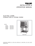
1
SERVICE MANUAL
ELECTRIC
COMBI
OVENS
MODEL
ML
VCE6H
126177
VCE10H
126178
VCE10F
126179
VCE20H
126172
VCE20F
126173
VCE10F SHOWN ON STAND
- NOTICE This Manual is prepared for the use of trained Vulcan Service
Technicians and should not be used by those not properly
qualified. If you have attended a Vulcan Service School for this
product, you may be qualified to perform all the procedures
described in this manual.
This manual is not intended to be all encompassing. If you have
not attended a Vulcan Service School for this product, you should
read, in its entirety, the repair procedure you wish to perform to
determine if you have the necessary tools, instruments and skills
required to perform the procedure. Procedures for which you do
not have the necessary tools, instruments and skills should be
performed by a trained Vulcan Service Technician.
Reproduction or other use of this Manual, without the express
written consent of Vulcan-Hart, is prohibited.
A product of VULCAN-HART
Form 24659 (September 1999)
LOUISVILLE, KY 40201-0696
ELECTRIC COMBI OVENS
TABLE OF CONTENTS
GENERAL . . . . . . . . . . . . . . . . . . . . . . . . . . . . . . . . . . . . . . . . . . . . . . . . . . . . . . . . . . . . . . . . . . . . . . . . . . . . .
Introduction . . . . . . . . . . . . . . . . . . . . . . . . . . . . . . . . . . . . . . . . . . . . . . . . . . . . . . . . . . . . . . . . . . . . . . . .
Operation . . . . . . . . . . . . . . . . . . . . . . . . . . . . . . . . . . . . . . . . . . . . . . . . . . . . . . . . . . . . . . . . . . . . . . . . . .
Cleaning . . . . . . . . . . . . . . . . . . . . . . . . . . . . . . . . . . . . . . . . . . . . . . . . . . . . . . . . . . . . . . . . . . . . . . . . . .
Stacking Kit Instructions . . . . . . . . . . . . . . . . . . . . . . . . . . . . . . . . . . . . . . . . . . . . . . . . . . . . . . . . . . . . . . .
Specifications . . . . . . . . . . . . . . . . . . . . . . . . . . . . . . . . . . . . . . . . . . . . . . . . . . . . . . . . . . . . . . . . . . . . . .
Water Supply . . . . . . . . . . . . . . . . . . . . . . . . . . . . . . . . . . . . . . . . . . . . . . . . . . . . . . . . . . . . . . . . . . .
Electrical . . . . . . . . . . . . . . . . . . . . . . . . . . . . . . . . . . . . . . . . . . . . . . . . . . . . . . . . . . . . . . . . . . . . . .
Oven Controls . . . . . . . . . . . . . . . . . . . . . . . . . . . . . . . . . . . . . . . . . . . . . . . . . . . . . . . . . . . . . . . . . . . . . .
Water Conditioning . . . . . . . . . . . . . . . . . . . . . . . . . . . . . . . . . . . . . . . . . . . . . . . . . . . . . . . . . . . . . . . . . .
Lubrication . . . . . . . . . . . . . . . . . . . . . . . . . . . . . . . . . . . . . . . . . . . . . . . . . . . . . . . . . . . . . . . . . . . . . . . . .
Tools . . . . . . . . . . . . . . . . . . . . . . . . . . . . . . . . . . . . . . . . . . . . . . . . . . . . . . . . . . . . . . . . . . . . . . . . . . . . .
4
4
4
4
4
4
4
5
6
7
7
7
REMOVAL AND REPLACEMENT OF PARTS . . . . . . . . . . . . . . . . . . . . . . . . . . . . . . . . . . . . . . . . . . . . . . . . . 8
Rack Guide/Filter/Exhaust Assembly . . . . . . . . . . . . . . . . . . . . . . . . . . . . . . . . . . . . . . . . . . . . . . . . . . . . . 8
Covers and Panels . . . . . . . . . . . . . . . . . . . . . . . . . . . . . . . . . . . . . . . . . . . . . . . . . . . . . . . . . . . . . . . . . . . 8
Oven Temperature Probe . . . . . . . . . . . . . . . . . . . . . . . . . . . . . . . . . . . . . . . . . . . . . . . . . . . . . . . . . . . . . 9
Programable Oven Control . . . . . . . . . . . . . . . . . . . . . . . . . . . . . . . . . . . . . . . . . . . . . . . . . . . . . . . . . . . 10
Manual Oven Controls . . . . . . . . . . . . . . . . . . . . . . . . . . . . . . . . . . . . . . . . . . . . . . . . . . . . . . . . . . . . . . . 11
Relay Board . . . . . . . . . . . . . . . . . . . . . . . . . . . . . . . . . . . . . . . . . . . . . . . . . . . . . . . . . . . . . . . . . . . . . . . 11
Blower and Motor . . . . . . . . . . . . . . . . . . . . . . . . . . . . . . . . . . . . . . . . . . . . . . . . . . . . . . . . . . . . . . . . . . . 12
Blower Motor Shaft Seal . . . . . . . . . . . . . . . . . . . . . . . . . . . . . . . . . . . . . . . . . . . . . . . . . . . . . . . . . . . . . 13
Heating Elements . . . . . . . . . . . . . . . . . . . . . . . . . . . . . . . . . . . . . . . . . . . . . . . . . . . . . . . . . . . . . . . . . . 13
Thermal Fuse(s) . . . . . . . . . . . . . . . . . . . . . . . . . . . . . . . . . . . . . . . . . . . . . . . . . . . . . . . . . . . . . . . . . . . 14
Steam Generator Drain Pump . . . . . . . . . . . . . . . . . . . . . . . . . . . . . . . . . . . . . . . . . . . . . . . . . . . . . . . . . 15
Vent Damper Assembly . . . . . . . . . . . . . . . . . . . . . . . . . . . . . . . . . . . . . . . . . . . . . . . . . . . . . . . . . . . . . . 15
Water Level Sensors and Water Equalization Tube . . . . . . . . . . . . . . . . . . . . . . . . . . . . . . . . . . . . . . . . . 16
Steam Generator Tank . . . . . . . . . . . . . . . . . . . . . . . . . . . . . . . . . . . . . . . . . . . . . . . . . . . . . . . . . . . . . . 17
Oven Door . . . . . . . . . . . . . . . . . . . . . . . . . . . . . . . . . . . . . . . . . . . . . . . . . . . . . . . . . . . . . . . . . . . . . . . . 18
Door Lamp . . . . . . . . . . . . . . . . . . . . . . . . . . . . . . . . . . . . . . . . . . . . . . . . . . . . . . . . . . . . . . . . . . . . . . . . 19
Oven Door Hinges . . . . . . . . . . . . . . . . . . . . . . . . . . . . . . . . . . . . . . . . . . . . . . . . . . . . . . . . . . . . . . . . . . 19
Door Magnetic Reed Switch . . . . . . . . . . . . . . . . . . . . . . . . . . . . . . . . . . . . . . . . . . . . . . . . . . . . . . . . . . . 20
Door Seal . . . . . . . . . . . . . . . . . . . . . . . . . . . . . . . . . . . . . . . . . . . . . . . . . . . . . . . . . . . . . . . . . . . . . . . . . 20
Door Locking Mechanism . . . . . . . . . . . . . . . . . . . . . . . . . . . . . . . . . . . . . . . . . . . . . . . . . . . . . . . . . . . . . 20
Oven Cavity Seal . . . . . . . . . . . . . . . . . . . . . . . . . . . . . . . . . . . . . . . . . . . . . . . . . . . . . . . . . . . . . . . . . . . 21
Power Supply Board and Transformer . . . . . . . . . . . . . . . . . . . . . . . . . . . . . . . . . . . . . . . . . . . . . . . . . . . 22
Contactors . . . . . . . . . . . . . . . . . . . . . . . . . . . . . . . . . . . . . . . . . . . . . . . . . . . . . . . . . . . . . . . . . . . . . . . . 22
Oven Cavity Drain . . . . . . . . . . . . . . . . . . . . . . . . . . . . . . . . . . . . . . . . . . . . . . . . . . . . . . . . . . . . . . . . . . 23
SERVICE PROCEDURES AND ADJUSTMENTS . . . . . . . . . . . . . . . . . . . . . . . . . . . . . . . . . . . . . . . . . . . . . .
Configuration Mode - Programable Control . . . . . . . . . . . . . . . . . . . . . . . . . . . . . . . . . . . . . . . . . . . . . . .
Diagnostic Test Mode - Programable Control . . . . . . . . . . . . . . . . . . . . . . . . . . . . . . . . . . . . . . . . . . . . . .
Configuration Mode - Manual Controls . . . . . . . . . . . . . . . . . . . . . . . . . . . . . . . . . . . . . . . . . . . . . . . . . . .
Diagnostic Test Mode - Manual Controls . . . . . . . . . . . . . . . . . . . . . . . . . . . . . . . . . . . . . . . . . . . . . . . . .
Service Error Lights . . . . . . . . . . . . . . . . . . . . . . . . . . . . . . . . . . . . . . . . . . . . . . . . . . . . . . . . . . . . . . . . .
Heating Elements . . . . . . . . . . . . . . . . . . . . . . . . . . . . . . . . . . . . . . . . . . . . . . . . . . . . . . . . . . . . . . . . . .
Oven Door Adjustment . . . . . . . . . . . . . . . . . . . . . . . . . . . . . . . . . . . . . . . . . . . . . . . . . . . . . . . . . . . . . . .
Buzzer Adjustment - Programable Control . . . . . . . . . . . . . . . . . . . . . . . . . . . . . . . . . . . . . . . . . . . . . . . .
Buzzer Adjustment - Manual Controls . . . . . . . . . . . . . . . . . . . . . . . . . . . . . . . . . . . . . . . . . . . . . . . . . . .
Clean Cycle Mode - Steam Generator Deliming . . . . . . . . . . . . . . . . . . . . . . . . . . . . . . . . . . . . . . . . . . . .
Battery Backup - Programable Control . . . . . . . . . . . . . . . . . . . . . . . . . . . . . . . . . . . . . . . . . . . . . . . . . . .
Page 2 of 68
24
24
25
26
28
29
30
30
32
32
33
35
ELECTRIC COMBI OVENS
ELECTRICAL OPERATION . . . . . . . . . . . . . . . . . . . . . . . . . . . . . . . . . . . . . . . . . . . . . . . . . . . . . . . . . . . . . .
Component Function . . . . . . . . . . . . . . . . . . . . . . . . . . . . . . . . . . . . . . . . . . . . . . . . . . . . . . . . . . . . . . . .
Component Location . . . . . . . . . . . . . . . . . . . . . . . . . . . . . . . . . . . . . . . . . . . . . . . . . . . . . . . . . . . . . . . .
Sequence of Operation . . . . . . . . . . . . . . . . . . . . . . . . . . . . . . . . . . . . . . . . . . . . . . . . . . . . . . . . . . . . . .
Heating Mode and Cavity Fan Speeds . . . . . . . . . . . . . . . . . . . . . . . . . . . . . . . . . . . . . . . . . . . . . . .
Heating Regulation . . . . . . . . . . . . . . . . . . . . . . . . . . . . . . . . . . . . . . . . . . . . . . . . . . . . . . . . . . . . . .
Steam Pre-Heat . . . . . . . . . . . . . . . . . . . . . . . . . . . . . . . . . . . . . . . . . . . . . . . . . . . . . . . . . . . . . . . .
Steam Regulation . . . . . . . . . . . . . . . . . . . . . . . . . . . . . . . . . . . . . . . . . . . . . . . . . . . . . . . . . . . . . . .
Water Injection (Humidifier) . . . . . . . . . . . . . . . . . . . . . . . . . . . . . . . . . . . . . . . . . . . . . . . . . . . . . . .
Cool Down Mode (Manual Controls) . . . . . . . . . . . . . . . . . . . . . . . . . . . . . . . . . . . . . . . . . . . . . . . . .
Programable Oven Control . . . . . . . . . . . . . . . . . . . . . . . . . . . . . . . . . . . . . . . . . . . . . . . . . . . . . . . .
Manual Oven Controls . . . . . . . . . . . . . . . . . . . . . . . . . . . . . . . . . . . . . . . . . . . . . . . . . . . . . . . . . . .
Wiring Diagrams . . . . . . . . . . . . . . . . . . . . . . . . . . . . . . . . . . . . . . . . . . . . . . . . . . . . . . . . . . . . . . . . . . .
6 Level . . . . . . . . . . . . . . . . . . . . . . . . . . . . . . . . . . . . . . . . . . . . . . . . . . . . . . . . . . . . . . . . . . . . . . .
10 Level . . . . . . . . . . . . . . . . . . . . . . . . . . . . . . . . . . . . . . . . . . . . . . . . . . . . . . . . . . . . . . . . . . . . . .
20 Level . . . . . . . . . . . . . . . . . . . . . . . . . . . . . . . . . . . . . . . . . . . . . . . . . . . . . . . . . . . . . . . . . . . . . .
Electric Heater Circuits . . . . . . . . . . . . . . . . . . . . . . . . . . . . . . . . . . . . . . . . . . . . . . . . . . . . . . . . . . . . . .
37
37
40
42
42
42
43
43
44
44
45
49
54
54
56
58
60
TROUBLESHOOTING . . . . . . . . . . . . . . . . . . . . . . . . . . . . . . . . . . . . . . . . . . . . . . . . . . . . . . . . . . . . . . . . . . 63
© VULCAN 1999
Page 3 of 68
ELECTRIC COMBI OVENS - GENERAL
GENERAL
INTRODUCTION
STACKING KIT INSTRUCTIONS
General
The procedures in this manual apply to all models
unless otherwise specified. All of the information,
illustrations and specifications contained in this
manual are based on the latest product information
available at the time of printing.
When servicing stacked ovens and disassembly is
required, refer to the Stacking Kit Instructions for
specific assembly procedures.
SPECIFICATIONS
Combi Ovens
The Electric Combi ovens provide convection heat,
steam heat or a combination of both in a single
compartment cooking chamber. Humidification is
provided from the internal steam generator or by
water injection into the oven cavity. When the water
is injected by means of an internal spray nozzle, it
vaporizes on contact with the hot interior surfaces.
The ovens are available in two depths, Half and Full
(half on 6 level only) and in three sizes (6H, 10H/F
and 20H/F).
OPERATION
Water Supply
The fact that a water supply is potable is no
guarantee that it is suitable for steam generation.
The supply connection to the steam generator
should be “treated” water and must be within the
guidelines listed below. For drain water cooling only,
an “untreated“ water supply connection should be
used.
Supply Pressure
(treated and untreated water)
Supply Connections
(treated and untreated water)
Water Hardness *
Refer to the Installation & Operation Manual for
specific operating instructions.
Chloride
PH factor (range)
20-80 psig
cold
2-4 grains per
gallon (gpg)
less than 30 ppm
7 to 8
(*17.1 ppm = 1 grain of hardness)
CLEANING
Refer to the Installation & Operation Manual for
specific cleaning instructions.
Page 4 of 68
ELECTRIC COMBI OVENS - GENERAL
Electrical
MACHINE AMPERAGE (3 PHASE/ 60HZ) 1
MODEL
POWER
(KW)
RECOMMENDED
CIRCUIT
PROTECTION 3
PER LINE 2
208V
240V
480V
208V
240V
480V
VCE6H
9
25
22
11
35
30
15
VCE10H
18
50
43
22
70
60
30
VCE10F
18
50
43
22
70
60
30
VCE20H
24
67
58
29
90
80
40
VCE20F
36
100
87
43
125
110
60
NOTES:
1. Amperage values in the table are nominal. Tolerance
is +5/-10%.
2. Line currents must be measured in full power
convection heat mode.
3. Complied in accordance with National Electric Code,
ANSI/NFPA 70, latest edition.
INDIVIDUAL AMPERAGE (3 PHASE/ 60HZ) 1
CONVECTION HEAT
MODEL
ELEMENTS
STEAM GENERATOR HEAT
208V
240V
480V
ELEMENTS
3
208V
240V
480V
1
22
19
10
8
2
45
39
19
22
8
2
45
39
19
58
29
8
3
67
58
29
87
43
8
4
89
77
39
KW
NO.
VCE6H
9
1
25
22
VCE10H
9
2
50
VCE10F
9
2
VCE20H
6
VCE20F
9
NOTES:
2
KW
NO.
11
8
43
22
50
43
4
67
4
100
1. Amperage values in the table are nominal. Tolerance is +5/-10%.
2. Convection heater currents must be measured in full power convection
heat mode.
3. Steam generator heater currents must be measured in full power steam
mode.
Page 5 of 68
ELECTRIC COMBI OVENS - GENERAL
OVEN CONTROLS
PROGRAMMABLE
DELUXE MANUAL
Page 6 of 68
STANDARD MANUAL
ELECTRIC COMBI OVENS - GENERAL
WATER CONDITIONING
LUBRICATION
Furnishing the steam generator with treated water to
reduce scale formation is important. Scale formation
will reduce steam output, cause premature
component failure, and shorten equipment life. Most
water supplies contain scale producing minerals
such as Calcium and Magnesium. As steam is
generated, the minerals remain and dissolve into
the water. As the concentration of these minerals
increases past a certain point, they precipitate from
the water and coat the inside of the steam
generator, heating elements, and water level
sensors. Because of the high temperature of these
surfaces, the precipitated minerals bake onto them
and become very difficult to remove.
This may cause several problems:
1.
Reduced heat transfer efficiency.
2.
Premature heating element failures.
3.
False readings from water level sensors.
Standard
The desired water properties can best be achieved
by using a properly maintained water treatment
system.
The water level probes in the steam generator use
ions in the water to detect the water level. Do not
use fully demineralized or de-ionized water
since it is "non conductive" and the water level
can not be detected.
Standard set of hand tools.
Metric set of hand tools.
VOM with AC current tester (any quality VOM
with a sensitivity of at least 20,000 ohms can
be used).
Gear puller to remove cavity fan.
Temperature meter with thermocouple.
Special
Other factors affecting steam generation are iron
content, amount of chloridation and dissolved
gases.
Cavity fan motor shaft seal requires lubrication
at replacement (White silicone grease 544268).
TOOLS
These problems are common to any manufacturer's
steamer regardless of design, but they can all be
minimized by furnishing the steam generator with
treated water.
Cavity fan motor has sealed bearings and
requires no additional lubrication.
The use of strainers, or filters will not remove
minerals from the water.
Water supplies vary from state to state and from
locations within a state. Therefore, Vulcan
recommends that a local water treatment specialist
be consulted before the installation of any steam
generating equipment.
Steamers that operate over a long period of time
without the benefit of a water treatment system,
which have developed a heavy scale build up,
should be cleaned before using the system.
Page 7 of 68
Red High Temperature RTV for door seal and
probes (P/N 544313 or 542949).
Grounding kit to protect control board(s) if
handled (P/N TL-84919).
Motor Shaft Centering Tool (P/N 359450).
28 pin EPROM extraction tool and 28 pin
EPROM insertion tool (purchase locally).
Scalekleen deliming chemical or the
recommended chemical for the water treatment
system in use for deliming of the steam
generator. (Scalekleen is available through the
Service Parts Distribution Center or locally
through an Everpure dealer)
ELECTRIC COMBI OVEN - REMOVAL AND REPLACEMENT OF PARTS
REMOVAL AND REPLACEMENT OF PARTS
RACK GUIDE/FILTER/EXHAUST
ASSEMBLY
1.
Turn the oven off.
2.
Remove the racks (if equipped).
3.
Push the rack guide to rear of oven to remove
the rack guide tabs from slots in the exhaust
assembly (10 level).
4.
Lift the rear of the rack guide up and pull the
guide out of the oven cavity.
5.
Lift the filter up, then pull forward to remove the
filter (2 filters on 20 level).
COVERS AND PANELS
WARNING: DISCONNECT THE ELECTRICAL
POWER TO THE MACHINE AT THE MAIN
CIRCUIT BOX. PLACE A TAG ON THE CIRCUIT
BOX INDICATING THE CIRCUIT IS BEING
SERVICED.
Side Panels
1.
Remove the screws from the side panel for the
side in need of access. Hold the panel in place
before removing the last screw.
2.
Access the inside edge of the panel at the
bottom rear corner and disconnect the ground
wire (if present).
3.
Remove the panel.
WARNING: DISCONNECT THE ELECTRICAL
POWER TO THE MACHINE AT THE MAIN
CIRCUIT BOX. PLACE A TAG ON THE CIRCUIT
BOX INDICATING THE CIRCUIT IS BEING
SERVICED.
6.
Lift up on exhaust assembly then pull forward
at bottom to clear the dowel pins.
7.
After lower dowel pins have been cleared,
remove assembly from top pins and remove
from oven.
NOTE: When re-installing the right side panel,
ensure the gasket at the rear of the control panel
seals properly against the front edge of the right
side panel.
4.
8.
Reverse procedure to install.
NOTE: Be sure the bottom of the exhaust assembly
is seated on the dowel pins and fan direction arrow
is pointing to left (facing oven).
Page 8 of 68
Reverse procedure to install.
ELECTRIC COMBI OVEN - REMOVAL AND REPLACEMENT OF PARTS
Rear Panel
1.
2.
OVEN TEMPERATURE PROBE
Remove the screws from the rear oven panel.
Hold the panel in place before removing the
last panel screw.
Access the inside edge of the panel at the
bottom left and disconnect the ground wire (if
present).
3.
Lower the panel to remove from oven.
4.
Reverse procedure to install.
WARNING: DISCONNECT THE ELECTRICAL
POWER TO THE MACHINE AT THE MAIN
CIRCUIT BOX. PLACE A TAG ON THE CIRCUIT
BOX INDICATING THE CIRCUIT IS BEING
SERVICED.
1.
Remove the rack guide, filter and exhaust
assembly as outlined under “RACK GUIDE/
FILTER/EXHAUST ASSEMBLY”.
2.
Remove both side panels as outlined under
“COVERS AND PANELS”.
3.
Remove the retaining nut from the probe inside
the oven (2 probes on 20 level) and lift bracket
off.
4.
Remove probe(s) through the left side of the
oven cavity.
Control Panel
1.
Remove the right side panel as outlined.
2.
Disconnect the ribbon cable, thermocouple
connector, ground leads and door switch
connector from the oven control board.
3.
NOTE: When replacing, use high temperature
silicone between the probe and the hole in the oven
cavity wall.
Remove the nuts at the top and bottom of
control panel that secure it to the frame.
CAUTION: Hold control panel during removal or
damage may result to the oven control if dropped.
4.
NOTE: Be sure to replace bracket around probe and
position as shown.
5.
Disconnect the probe leads from the control
board connector.
6.
Reverse procedure to install.
Reverse procedure to install.
NOTE: When tightening retaining nut, probe will
rotate unless secured. Do not clamp down on probe
or damage may result.
Page 9 of 68
ELECTRIC COMBI OVEN - REMOVAL AND REPLACEMENT OF PARTS
PROGRAMABLE OVEN
CONTROL
4.
Remove the hex nuts securing the CPU board
to the display/keypad board.
5.
Pull outwards on the CPU board and lift it off
from the display/keypad board pin connections.
WARNING: DISCONNECT THE ELECTRICAL
POWER TO THE MACHINE AT THE MAIN
CIRCUIT BOX. PLACE A TAG ON THE CIRCUIT
BOX INDICATING THE CIRCUIT IS BEING
SERVICED.
CAUTION: Certain components in this system
are subject to damage by electrostatic discharge
during field repairs. A field service ground kit is
available to prevent damage. The field service
grounding kit must be used anytime the control
board is handled.
1.
Remove the right side panel as outlined under
“COVERS AND PANELS”.
2.
Disconnect the ribbon cable, connectors and
ground leads from the oven control board.
3.
Remove the cover from the oven control by
removing the mounting nuts at the top and
bottom.
NOTE: When installing the control board onto the
keypad board, make sure that the pins on the
keypad board are aligned with the plug on the
control board.
Page 10 of 68
ELECTRIC COMBI OVEN - REMOVAL AND REPLACEMENT OF PARTS
6.
Remove the display/keypad board from the
control panel by removing the mounting nuts.
7.
Reverse procedure to install.
4.
Remove the oven control board from the
control panel by removing the mounting nuts.
5.
Reverse procedure to install.
MANUAL OVEN CONTROLS
RELAY BOARD
WARNING: DISCONNECT THE ELECTRICAL
POWER TO THE MACHINE AT THE MAIN
CIRCUIT BOX. PLACE A TAG ON THE CIRCUIT
BOX INDICATING THE CIRCUIT IS BEING
SERVICED.
CAUTION: Certain components in this system
are subject to damage by electrostatic discharge
during field repairs. A field service ground kit is
available to prevent damage. The field service
grounding kit must be used anytime the control
board is handled.
1.
Remove the right side panel as outlined under
“COVERS AND PANELS”.
2.
Disconnect the ribbon cable, thermocouple
connector, ground leads and door switch
connector from the oven control board.
3.
WARNING: DISCONNECT THE ELECTRICAL
POWER TO THE MACHINE AT THE MAIN
CIRCUIT BOX. PLACE A TAG ON THE CIRCUIT
BOX INDICATING THE CIRCUIT IS BEING
SERVICED.
CAUTION: Certain components in this system
are subject to damage by electrostatic discharge
during field repairs. A field service ground kit is
available to prevent damage. The field service
grounding kit must be used anytime the control
board is handled.
1.
Remove the right side panel as outlined under
“COVERS AND PANELS”.
2.
Disconnect lead wires from the relay board.
Remove the cover from the oven control board
by removing the mounting nuts at the top and
bottom.
Page 11 of 68
ELECTRIC COMBI OVEN - REMOVAL AND REPLACEMENT OF PARTS
3.
4.
Release the clips on the back of the mounting
rail.
NOTE: If only the blower is being removed, reverse
the procedure at this point to install.
5.
Remove the rear panel as outlined under
“COVERS AND PANELS”.
6.
Disconnect the lead wires from the motor.
7.
Remove the motor from the back of the oven
by removing the mounting nuts.
8.
Remove the cover plate and seal from inside
the oven cavity.
Reverse procedure to install.
BLOWER AND MOTOR
WARNING: DISCONNECT THE ELECTRICAL
POWER TO THE MACHINE AT THE MAIN
CIRCUIT BOX. PLACE A TAG ON THE CIRCUIT
BOX INDICATING THE CIRCUIT IS BEING
SERVICED.
Removal
1.
Remove the rack guide, filter and exhaust
assembly as outlined under “RACK GUIDE/
FILTER/EXHAUST ASSEMBLY”.
2.
Loosen bolt (one turn) that secures the blower
and install puller.
3.
Tighten the puller, then tap the puller with a
hammer to loosen the blower from the motor
shaft.
4.
Remove the puller, bolt, washer and blower
from the motor shaft.
NOTE: You may have to drive the seal out from the
back of the oven.
Page 12 of 68
ELECTRIC COMBI OVEN - REMOVAL AND REPLACEMENT OF PARTS
Installation
1.
Mount the motor to the back of the oven.
Tighten the bolts enough to hold the motor in
place, but allow some movement.
2.
Ensure that the motor shaft is centered (use
shaft centering tool) in the motor shaft hole and
tighten mounting bolts.
NOTE: Remove all traces of motor seal grease from
the motor shaft.
7.
Install the seal cover plate and then the blower.
HEATING ELEMENTS
3.
Remove the shaft centering tool.
4.
Connect the lead wires to the motor.
5.
Install seal and cover as outlined under
“BLOWER MOTOR SHAFT SEAL”.
NOTE: Remove all traces of motor seal grease from
the motor shaft.
6.
Install the blower wheel.
7.
Install exhaust assembly, filter, and rack guide
as outlined under “RACK
GUIDE/FILTER/EXHAUST ASSEMBLY”.
8.
Install rear panel as outlined under “COVERS
AND PANELS”.
BLOWER MOTOR SHAFT SEAL
WARNING: DISCONNECT THE ELECTRICAL
POWER TO THE MACHINE AT THE MAIN
CIRCUIT BOX. PLACE A TAG ON THE CIRCUIT
BOX INDICATING THE CIRCUIT IS BEING
SERVICED.
1.
Remove blower as outlined under “BLOWER
AND MOTOR”.
2.
Remove motor seal cover plate.
3.
Remove the seal from the recess in the rear
oven wall.
WARNING: DISCONNECT THE ELECTRICAL
POWER TO THE MACHINE AT THE MAIN
CIRCUIT BOX. PLACE A TAG ON THE CIRCUIT
BOX INDICATING THE CIRCUIT IS BEING
SERVICED.
Oven Cavity
1. Remove the rack guide, filter and exhaust
assembly as outlined under “RACK GUIDE/
FILTER/EXHAUST ASSEMBLY”.
2. From inside the oven cavity, remove the nuts
from the heating element stand-offs for the
element being replaced.
3. Remove the rear panel as outlined under
“COVERS AND PANELS”.
4. Disconnect the lead wires from the elements at
the rear of the oven.
5. Remove the nuts and washers from the
element being replaced then remove the
element.
NOTE: You may have to drive the seal out from the
back of the oven.
4.
Fill replacement seal cover with white silicone
grease.
5.
Assemble the motor seal with the convex part
of the spring toward the motor.
6.
Apply red high temperature RTV to the outer
edge of the seal to help hold it in the recess
and install the seal with the seal cover toward
the front of the oven cavity.
6.
Page 13 of 68
Reverse procedure to install.
ELECTRIC COMBI OVEN - REMOVAL AND REPLACEMENT OF PARTS
Steam Generator
1.
Turn off the water supply to the steam
generator.
2.
Remove the right side panel as outlined under
“COVERS AND PANELS”.
3.
Remove the thermal fuse and protective sleeve
from the heater thermowell.
4.
Disconnect the heating element lead wire
connections.
5.
Remove the heating element from the steam
generator by removing the mounting nuts.
NOTE: When installing a new heater, use the
supplied gasket and ensure the mating surfaces are
clean.
6.
Disconnect the thermal fuse(s) lead wire
connections.
3.
Remove the thermal fuse and protective sleeve
from the heater thermowell.
4.
Reverse procedure to install.
NOTE: When replacing thermal fuse, be sure to
insert the protective sleeve and thermal fuse
together. The protective sleeve must be inserted
into the heater thermowell with the fuse to avoid
chafing of the fuse leads.
Reverse procedure to install.
THERMAL FUSE(S)
WARNING: DISCONNECT THE ELECTRICAL
POWER TO THE MACHINE AT THE MAIN
CIRCUIT BOX. PLACE A TAG ON THE CIRCUIT
BOX INDICATING THE CIRCUIT IS BEING
SERVICED.
1.
2.
NOTE: When replacing thermal fuse do not pull the
lead wires apart. This may break the contact
junction or damage the connections.
Remove the right side panel as outlined under
“COVERS AND PANELS”.
Page 14 of 68
ELECTRIC COMBI OVEN - REMOVAL AND REPLACEMENT OF PARTS
STEAM GENERATOR DRAIN
PUMP
1.
VENT DAMPER ASSEMBLY
Turn off the oven and allow the steam
generator to drain.
WARNING: DISCONNECT THE ELECTRICAL
POWER TO THE MACHINE AT THE MAIN
CIRCUIT BOX. PLACE A TAG ON THE CIRCUIT
BOX INDICATING THE CIRCUIT IS BEING
SERVICED.
2.
Turn off the water supply.
3.
Remove the right side panel as outlined under
“COVERS AND PANELS”.
4.
Disconnect lead wires and hoses connected to
the drain pump.
5.
Remove the bolts from the mounting bracket
that secure the pump.
WARNING: DISCONNECT THE ELECTRICAL
POWER TO THE MACHINE AT THE MAIN
CIRCUIT BOX. PLACE A TAG ON THE CIRCUIT
BOX INDICATING THE CIRCUIT IS BEING
SERVICED.
VENT DAMPER ASSEMBLY DIAGRAM
Vent Motor
6.
1.
Remove the right side panel as outlined under
“COVERS AND PANELS”.
2.
Disconnect the lead wires from the switch and
motor.
3.
Remove the screw and nut behind the motor
assembly that connects motor to shaft
extension rod.
4.
Remove the motor and switch assembly from
the oven by sliding the mounting bracket out
from the oven frame.
5.
Reverse procedure to install.
Reverse procedure to install.
Page 15 of 68
ELECTRIC COMBI OVEN - REMOVAL AND REPLACEMENT OF PARTS
Sealing Washer
1.
2.
Remove the right side panel as outlined under
“COVERS AND PANELS”.
4.
Rotate the extension rod approximately 90
degrees by hand.
5.
Examine the vent from inside the cavity.
Open the oven door and remove the rack
guide, filter and exhaust assembly as outlined
under “RACK GUIDE/FILTER/EXHAUST
ASSEMBLY”.
A.
If the mounting nut is visible, proceed to
step 6.
B.
If the mounting nut is not visible, then the
extension rod needs to rotate
approximately 90 degrees more.
WARNING: THE FOLLOWING STEPS REQUIRE
POWER TO BE APPLIED TO THE UNIT DURING
THE ADJUSTMENT. USE EXTREME CAUTION AT
ALL TIMES.
6.
Remove the nut securing both shutters and the
sealing washer to the extension rod then
remove the shutters and sealing washer.
3.
Reconnect the electrical power to the machine
at the main circuit box.
7.
Remove the shutter screw from the extension
rod.
4.
Close the door, turn the oven ON and press the
Start/Stop button.
8.
5.
Observe the rotation of the vent motor cam.
When the cam stops turning then the vent
should be closed.
Release the snap ring on the left end of the
shaft (if facing oven) and pull shaft extension
out.
NOTE: When the oven is turned OFF or the door is
opened, the vent should open automatically.
6.
8.
9.
9.
Disconnect the electrical power to the machine
at the main circuit box. Place a tag on the
circuit box indicating the circuit is being
serviced.
NOTE: Power to the oven must be removed in this
manner. If the oven is turned OFF or the door is
opened, the vent will re-open automatically.
7.
NOTE: If the washers on the exterior of the vent
housing come loose, red silicone must be re-applied
to prevent steam leakage above the oven cavity.
Open the oven door and examine the vent from
inside the cavity.
A.
If the mounting nut is visible, proceed to
step 8.
B.
If the mounting nut is not visible, then the
vent needs to rotate 180 degrees.
Reconnect power to the machine and
repeat steps 3 through 7A.
Reverse procedure to install.
WATER LEVEL SENSORS AND
WATER EQUALIZATION TUBE
1.
Turn the oven off and allow steam generator
tank to drain.
WARNING: DISCONNECT THE ELECTRICAL
POWER TO THE MACHINE AT THE MAIN
CIRCUIT BOX. PLACE A TAG ON THE CIRCUIT
BOX INDICATING THE CIRCUIT IS BEING
SERVICED.
2.
Turn off the water supply.
3.
Remove the nut securing both shutters and the
sealing washer to the shaft extension rod then
remove the shutters and sealing washer.
Remove the right side panel as outlined under
”COVERS AND PANELS”.
4.
Disconnect lead wires and hose clamps from
the water equalization tube.
Install new sealing washer and re-assemble.
NOTE: Some water will continue to drain out.
Shaft Extension
1.
Remove the left, right and rear panels as
outlined under “COVERS AND PANELS”.
2.
Open the oven door and remove the rack
guide, filter and exhaust assembly as outlined
under “RACK GUIDE/FILTER/EXHAUST
ASSEMBLY”.
3.
Remove the screw and nut behind the motor
assembly that connects motor to shaft
extension rod.
Page 16 of 68
ELECTRIC COMBI OVEN - REMOVAL AND REPLACEMENT OF PARTS
5.
Remove the water equalization tube.
4.
Disconnect water and steam equalization tube
from the steam generator. If necessary, loosen
or remove drain pump mounting nuts to
remove tube.
10 LEVEL SHOWN
6.
Reverse procedure to install.
A.
NOTE: Unless replacing the heating
element(s), it not necessary to remove the
heating element lead wires.
STEAM GENERATOR TANK
1.
B.
Turn the oven off and allow the steam
generator tank to drain.
WARNING: DISCONNECT THE ELECTRICAL
POWER TO THE MACHINE AT THE MAIN
CIRCUIT BOX. PLACE A TAG ON THE CIRCUIT
BOX INDICATING THE CIRCUIT IS BEING
SERVICED.
2.
Turn off the water supply to the steam
generator
3.
Remove the right side and rear panels as
outlined under “COVERS AND PANELS”.
Remove heating elements from steam
generator tank and place to the side.
On 6 and 10 levels, remove clamp from
the steam exhaust hose at the top of
steam generator and disconnect hose. On
20 levels, remove the nuts securing the
steam exhaust pipe to the outside of the
cavity.
NOTE: When replacing tank on 20 levels, be
sure to seal the mating surface between the
exhaust pipe and cavity wall with RTV.
5.
Remove the nuts from the tank mounting studs
and bracket (at bottom) then remove the steam
generator from the oven.
6.
Remove insulation from the old steam
generator and use on the replacement steam
generator.
7.
Reverse procedure to install.
Page 17 of 68
ELECTRIC COMBI OVEN - REMOVAL AND REPLACEMENT OF PARTS
4.
OVEN DOOR
Open the inner door glass and remove the cring clamps from the rear snap catches, unsnap
at the rear then lift off.
WARNING: DISCONNECT THE ELECTRICAL
POWER TO THE MACHINE AT THE MAIN
CIRCUIT BOX. PLACE A TAG ON THE CIRCUIT
BOX INDICATING THE CIRCUIT IS BEING
SERVICED.
Removal
1.
Remove the left and right side panels as
outlined under “COVERS AND PANELS”.
2.
Disconnect the lead wires to the lamp on the
power supply board terminal block and route
them so they can be pulled through the hole in
the frame when the door is removed.
3.
Support the door, remove the screws from
each hinge block on the oven and remove
door.
Disassembly
CAUTION: When replacing the inner door glass,
it must be installed with the conductive side
toward the front of the oven. Use an ohmmeter
to verify the conductive side. Set the meter to
read ohms and touch glass with the meter leads.
A resistance will be measured but will vary
depending on the distance between the meter
leads, grease and/or other substances on the
glass.
1.
Remove the door from the oven as outlined
above in “REMOVAL”.
5.
Remove the bolts securing the top and bottom
hinges to the door.
2.
Lay the door on a flat surface with the inside of
the door facing up.
6.
3.
Lift up along the inner door glass edge near the
door latch and unsnap the glass from the “snap
catches” in the oven door.
Remove the drip tray, remaining screws from
the inner door panel, the screws at the left,
right and bottom of the door and remove the
door handle.
7.
Lift the inner door panel from the outer door
frame.
8.
Remove the outer door glass.
9.
Reverse procedure to install.
4.
Reverse procedure to install.
10. Adjust the door as outlined under “OVEN
DOOR ADJUSTMENT” in “SERVICE
PROCEDURES AND ADJUSTMENTS”.
Page 18 of 68
ELECTRIC COMBI OVEN - REMOVAL AND REPLACEMENT OF PARTS
DOOR LAMP
OVEN DOOR HINGES
WARNING: DISCONNECT THE ELECTRICAL
POWER TO THE MACHINE AT THE MAIN
CIRCUIT BOX. PLACE A TAG ON THE CIRCUIT
BOX INDICATING THE CIRCUIT IS BEING
SERVICED.
1. Remove the screws holding the cover and
gasket.
WARNING: DISCONNECT THE ELECTRICAL
POWER TO THE MACHINE AT THE MAIN
CIRCUIT BOX. PLACE A TAG ON THE CIRCUIT
BOX INDICATING THE CIRCUIT IS BEING
SERVICED.
1. Remove and disassemble the door as outlined
under “OVEN DOOR”.
2. Remove the light lead wire from the hinge.
NOTE: Strip 3 inches of the shielding away from the
wires at the terminal end to allow the terminals to be
fed through the hinge one at a time.
3.
Remove the cotter pins from the shaft and
remove the shaft from the hinges.
4.
Reverse procedure to install.
2.
Pull the lamp and socket assembly out from the
door.
3. Hold the lamp assembly and grasp the bulb
using a cloth.
NOTE: Do not touch the Halogen lamp with bare
hands. If lamp is exposed to oil from the skin, the
life will be reduced. Ensure lamp is free from oil and
dirt before replacing.
4.
5.
Pull up on light bulb to remove it from socket.
Reverse procedure to install.
Page 19 of 68
ELECTRIC COMBI OVEN - REMOVAL AND REPLACEMENT OF PARTS
DOOR MAGNETIC REED SWITCH
5.
Apply red silicone to the replacement seal and
install the seal to the glass edge. The vent
holes must be installed to the outside to allow
the seal to contract when the door is closed.
6.
Adjust door closure, if necessary, as outlined
under “OVEN DOOR AND DOOR LOCK
ADJUSTMENT” in “SERVICE PROCEDURES
AND ADJUSTMENTS”.
WARNING: DISCONNECT THE ELECTRICAL
POWER TO THE MACHINE AT THE MAIN
CIRCUIT BOX. PLACE A TAG ON THE CIRCUIT
BOX INDICATING THE CIRCUIT IS BEING
SERVICED.
1.
Remove the right side panel as outlined under
“COVERS AND PANELS”.
2.
Remove the nuts that secure the door switch
mounting bracket to the bottom of the control
panel. On 20 levels, the switch is mounted to
the underside of the channel for the door
handle (no bracket required).
3.
Disconnect the switch lead wires.
4.
Remove the switch from the oven.
6 AND 10 LEVELS
5.
Reverse procedure to install and check for
proper operation.
DOOR LOCKING MECHANISM
1.
Turn the oven off.
WARNING: DISCONNECT THE ELECTRICAL
POWER TO THE MACHINE AT THE MAIN
CIRCUIT BOX. PLACE A TAG ON THE CIRCUIT
BOX INDICATING THE CIRCUIT IS BEING
SERVICED.
2.
Open the oven door.
Replacement
3.
Remove seal from the edge of the inside glass.
1.
4.
Clean the edge of the glass, remove the old
adhesive.
Remove the right side panel as outlined under
“COVERS AND PANELS”.
2.
Disconnect the lead wires to the motor and
switches.
3.
Remove the nuts from the mounting studs and
remove the assembly from the oven.
DOOR SEAL
Page 20 of 68
ELECTRIC COMBI OVEN - REMOVAL AND REPLACEMENT OF PARTS
4.
Remove the spring and positioning plate from
the locking arm.
5.
Reverse procedure to install and adjust as
outlined under “OVEN DOOR ADJUSTMENT”
in “SERVICE PROCEDURES AND
ADJUSTMENTS”.
Disassembly
1. Remove the three screws that secure the motor
and switch assembly.
2. Remove the motor, gear box and switch
assembly from the locking mechanism.
Remove the two bolts from the locking
mechanism. The springs, locking arm and
bushings can be removed.
3.
4.
The springs, locking arm and bushings can be
removed.
5.
Reverse procedure to install.
OVEN CAVITY SEAL
1.
Open the door.
2.
Pull the seal from the groove around the oven
cavity.
3.
Push the arrow head tip of the gasket into the
groove. Install the four corners first.
4.
Start at the corners and work to the middle of
each side, being careful not to stretch the
replacement gasket.
5.
Check the door for proper operation and adjust
if necessary, as outlined under “OVEN DOOR
AND DOOR LOCK ADJUSTMENT” in
“SERVICE PROCEDURES AND
ADJUSTMENTS”.
Remove the two bolts from the locking
mechanism.
Page 21 of 68
ELECTRIC COMBI OVEN - REMOVAL AND REPLACEMENT OF PARTS
POWER SUPPLY BOARD
AND TRANSFORMER
CONTACTORS
WARNING: DISCONNECT THE ELECTRICAL
POWER TO THE MACHINE AT THE MAIN
CIRCUIT BOX. PLACE A TAG ON THE CIRCUIT
BOX INDICATING THE CIRCUIT IS BEING
SERVICED.
1.
2.
Remove the right side panel as outlined under
“COVERS AND PANELS”.
WARNING: DISCONNECT THE ELECTRICAL
POWER TO THE MACHINE AT THE MAIN
CIRCUIT BOX. PLACE A TAG ON THE CIRCUIT
BOX INDICATING THE CIRCUIT IS BEING
SERVICED.
1.
Remove the right side panel as outlined under
“COVERS AND PANELS”.
2.
Disconnect lead wires for the contactor being
replaced.
3.
Remove the jumper bars from the contactors.
4.
Pull the locking tab out at the contactor base to
release the catch and remove contactor from
mounting bracket.
5.
Reverse procedure to install.
Disconnect lead wire connections and ribbon
cable from the board.
3.
Loosen the two nuts securing the assembly to
the mounting bracket and lift the assembly off
the bracket.
4.
Reverse procedure to install.
NOTE: Ensure transformer tap wire is in the position
that corresponds to the machine data plate voltage.
Refer to the “power supply board and transformer
(1T) “ component on the wiring diagram for proper
connection of the individual lead wires.
Page 22 of 68
ELECTRIC COMBI OVEN - REMOVAL AND REPLACEMENT OF PARTS
OVEN CAVITY DRAIN
6.
Remove the drain vent pipe from the drain.
7.
Disconnect the drain cool down water hose
from the drain nipple extension.
8.
Unscrew the drain line piping from the bottom
of the oven then remove the oven drain.
9.
Reverse procedure to install.
WARNING: DISCONNECT THE ELECTRICAL
POWER TO THE MACHINE AT THE MAIN
CIRCUIT BOX. PLACE A TAG ON THE CIRCUIT
BOX INDICATING THE CIRCUIT IS BEING
SERVICED.
1.
Open the oven cavity door.
2.
Lift up the oven cavity drain grate to remove.
3.
Unscrew t-bar nut to release drain at the front.
4.
Remove rear panel as outlined under
“COVERS AND PANELS”.
5.
Disconnect the drain pump discharge hose
from the drain vent pipe.
Page 23 of 68
ELECTRIC COMBI OVENS - SERVICE PROCEDURES AND ADJUSTMENTS
SERVICE PROCEDURES AND ADJUSTMENTS
WARNING: CERTAIN PROCEDURES IN THIS SECTION REQUIRE ELECTRICAL TEST OR
MEASUREMENTS WHILE POWER IS APPLIED TO THE MACHINE. EXERCISE EXTREME CAUTION AT ALL
TIMES. IF TEST POINTS ARE NOT EASILY ACCESSIBLE, DISCONNECT POWER, ATTACH TEST
EQUIPMENT AND REAPPLY POWER TO TEST.
CONFIGURATION MODE PROGRAMABLE CONTROL
WARNING: DISCONNECT THE ELECTRICAL
POWER TO THE MACHINE AT THE MAIN
CIRCUIT BOX. PLACE A TAG ON THE CIRCUIT
BOX INDICATING THE CIRCUIT IS BEING
SERVICED.
1.
Remove the rear panel as outlined under
“COVERS AND PANELS”.
2.
Identify the type of convection fan motor(s) on
the oven before setting the motor values in
step 9 and 10.
3.
Reverse procedure to install.
4.
Re-connect power to the oven.
The configuration mode can be entered only when
the oven is OFF. Returning to the normal operating
mode can be done at any time by pressing the OFF
key to save the configuration settings and exit the
configuration mode.
4.
The EPROM revision level is displayed in the
time display and “Conf” is displayed in the
temperature display. To verify the EPROM is at
the current revision level, refer to the Technical
Service Bulletins. Press the START/STOP key
to advance to the next step.
5.
HHH is displayed in the time display and the
total cooking hours of the oven is displayed in
the temperature display. Press the TEMP UP
key to increase number of hours or the TEMP
DOWN key to decrease the number of hours. If
the current number of hours is acceptable,
press START/STOP key to advance to the next
step.
NOTE: If a configuration parameter is selected and
not changed within 3 seconds, the control will
automatically advance to the next step without
pressing the START/STOP key.
6.
bbb flashes and is displayed in the time
display, the frequency number is displayed in
the temperature display and the buzzer should
be sounding. Press the TEMP UP or TEMP
DOWN keys to set the buzzer frequency (000 =
continuous and 255 = very slow intervals)
number. A good setting to start with is 050 or
any number that is preferable to the customer.
If the setting is acceptable, press the
START/STOP key to advance to the next step.
7.
uuu is displayed in the time display and the
steam temperature setting is displayed in the
temperature display. The steam temperature
setting is the boiling point adjustment for
elevation and must be set to achieve optimum
results. Press the TEMP UP key to increase
number or TEMP DOWN key to decrease
number. Set the temperature according to the
table below. Press the START/STOP key to
advance to the next step.
To Perform:
1.
To enter the configuration mode press the
TIME, TIME UP and TIME DOWN keys
simultaneously for 3 seconds. In the time
display, C and F will be displayed. In the
temperature display, “Conf” will be displayed.
2.
Press the TIME UP key for Fahrenheit or TIME
DOWN key for Celsius. The blinking letter
indicates the temperature scale selected. The
control will automatically advance to the next
step, approximately three seconds after the
selection is made. To manually advance to the
next step, press the START/STOP key.
3.
dSC is displayed in the time display and the
number of clean cycles completed (deliming of
steam generator) is displayed in the
temperature display. The number cannot be
changed or modified. Press the
START/STOP key to advance to the next step.
Page 24 of 68
ELECTRIC COMBI OVENS - SERVICE PROCEDURES AND ADJUSTMENTS
NOTE: The temperature selected in the table below
will also be the highest starting point temperature
available, when the steam mode is selected.
CONVECTION FAN
MOTOR TYPE
POSITION 1
(MINIMUM)
POSITION 2
(MAXIMUM)
1 motor Leroy-Somer
(Hanning)
8
55
1 motor Brook-Crompton *
8
60
ELEVATION
(FT)
TEMPERATURE
(°F)
Sea level to 500
212
500 to 1000
211
1,000 to 2,000
209
2 motors Leroy-Somer
(Hanning)
46
120
2,000 to 3,000
207
2 motors Brook-Crompton
30
90
3,000 to 4,000
205
4,000 to 5,000
204
1 motor Leroy-Somer
(Hanning) and 1 motor
Brook-Crompton
38
105
5,000 to 6,000
202
6,000 to 7,000
200
7,000 to 8,000
198
8,000 to 9,000
196
9,000 to 10,000
195
Above 10,000
194
NOTE:
8.
9.
CONVECTION FAN MOTOR
VALUE
CCC is displayed in the time display and the
convection temperature limit is displayed in the
temperature display. Press the TEMP UP key
to increase number (482°F to 518°F) and
TEMP DOWN key to decrease number. Set the
temperature to read 518°F. Press the
START/STOP key to advance to the next step.
1 - - is displayed in the time display and the
minimum value for the convection fan motor is
displayed in the temperature display. Press the
TEMP UP key to increase number and TEMP
DOWN key to decrease number. Set according
to Position 1 (minimum) in the table below. If
the value is correct, press the START/STOP
key to advance to the next step.
10. 2 - - is displayed in the time display and a
maximum value for the convection fan motor is
displayed in the temperature display. Press the
TEMP UP key to increase number and the
TEMP DOWN key to decrease number. Set
according to Position 2 (maximum) in the table
below. If the value is correct, press the
START/STOP key to advance to the next step.
(*) Ovens are shipped from the factory with this
motor and the oven control is configured
accordingly.
The values correspond to the current limits only
and are not the actual current draw of the motor.
11. If all the values have been entered correctly,
press the OFF key to save the configuration
settings and exit the configuration mode. To
review or change a configuration value press
the START/STOP key to return to step 1.
DIAGNOSTIC TEST MODE PROGRAMABLE CONTROL
The test mode can be entered only when the oven is
OFF. The five tests are run in sequence (1 - 5) and
are indicated by the position of the illuminated LED
in the bar graph of the combi mode key.
The test are performed in a fixed sequence of:
1.
ROM (automatically)
2.
RAM (automatically)
3.
Displays and LED’s
4.
Relays (relay on for max. of 2 seconds)
5.
Keypad
To Perform:
1.
To enter the test mode press the TEMP, TEMP
UP and TEMP DOWN keys simultaneously for
3 seconds. The word “test” will be displayed in
the temperature display.
2.
If a ROM or RAM error is detected, a error
code (01 = ROM and 02 = RAM) will be
displayed on the temperature display and will
repeat until a key is pushed to exit this test. If
no errors are detected, the control advances to
the next test and runs it automatically.
Page 25 of 68
ELECTRIC COMBI OVENS - SERVICE PROCEDURES AND ADJUSTMENTS
3.
4.
The DISPLAY and LED test consists of flashing
all displays and LED’s. The word “test” will flash
intermittently as the temperature display is
tested. Verify all the DISPLAYS and LED’s are
flashing. This test will continue until a key is
pressed to advance to the next step.
The RELAY test consist of selecting a
particular relay by its code number (01 to 11)
with the TEMP UP and TEMP DOWN keys.
The initial code displayed in the temperature
display is 01 for relay K1. Press the TEMP key
to energize the selected relay for a maximum
of 2 seconds. Verify that each selected relay
(K1 to K10) is functioning. See table below. To
exit this test and proceed to the next, press the
OFF key.
RELAY
COMPONENT
01
K1
door motor
02
K2
cavity vent motor
03*
K6
contactor KM1 (half power, full speed)
04
K3
cooling fan(s) and door light only
05
K3, K4
06
K5
07
K3, K5
08*
K7
contactor KM2 (half power, half speed);
on 20 levels only, contactor KM3 and
drain cool down solenoid.
09*
K8
contactor KM3 and drain cool down
solenoid on 6 & 10 levels;
contactor KM5 on 20 levels only
(steam generator heating elements)
10*
K10
contactor KM7
(convection heating elements)
11*
K9
contactor KM6
(convection heating elements)
NO.
KEY
NO.
ON
01
TEMP
12
OFF
02
TEMP DOWN
13
HOT AIR
03
TEMP UP
14
STEAM
04
DELTA T
15
COMBI
05
PROG
16
START/STOP
06
ENTER
17
PHASE
07
ENTER DOWN
18
TIME
08
ENTER UP
19
TIME DOWN
09
FAN SPEED
20
TIME UP
10
HUMIDIFIER
21
PROBE
11
6.
CODE
To exit the diagnostic test mode, press and
hold the OFF key for approximately 3 seconds.
CONFIGURATION MODE MANUAL CONTROLS
water injection solenoid (humidifier)
drain pump
water fill solenoid
NOTE: Asterisk (*) indicates relay is checked but contactor not
engaged. No noticeable external component operates.
5.
KEY
The keypad test consist of pressing each key to
check its functionality. Initially, 02 is displayed
in the time display and “test” is displayed in the
temperature display. With each successful key
press, the number of the key is displayed in
the time display. Each key is numbered,
starting with number 01 (ON) in the upper left
corner of the control and ends at 21
(humidifier) on the lower right corner. See table
below. Verify that all keypad buttons are
functioning properly.
WARNING: DISCONNECT THE ELECTRICAL
POWER TO THE MACHINE AT THE MAIN
CIRCUIT BOX. PLACE A TAG ON THE CIRCUIT
BOX INDICATING THE CIRCUIT IS BEING
SERVICED.
1.
Remove the rear panel as outlined under
“COVERS AND PANELS”.
2.
Identify the type of convection fan motor(s) on
the oven before setting the motor values in
step 9 and 10.
3.
Reverse procedure to install.
4.
Re-connect power to the oven.
The configuration mode can be entered only when
the oven is OFF. Returning to the normal operating
mode can be done at any time by pressing the
START key to save the configuration settings and
exit the configuration mode.
To Perform:
1.
To enter the configuration mode press the
TIME and TEMP keys simultaneously for 3
seconds. In the temperature display, “Conf” will
be displayed. Press the TIME key to advance
to the next step.
2.
C and F will be displayed in the time display.
Rotate the adjustment knob counterclockwise
for Celsius and clockwise for Fahrenheit. The
blinking letter indicates the temperature scale
selected. Accept the selection by pressing the
TIME key to advance to the next step.
Page 26 of 68
ELECTRIC COMBI OVENS - SERVICE PROCEDURES AND ADJUSTMENTS
3.
4.
5.
6.
7.
dSCL is displayed in the time display and the
number of clean cycles completed (deliming of
steam generator) is displayed in the
temperature display. The number cannot be
changed or modified. Press the TIME key to
advance to the next step.
ELEVATION
(FT)
TEMPERATURE
(°F)
Sea level to 500
212
500 to 1000
211
1,000 to 2,000
209
The EPROM revision level is displayed in the
time display and “Conf” is displayed in the
temperature display. To verify the EPROM is at
the current revision level, refer to the latest
Technical Service Bulletins. Press the TIME
key to advance to the next step.
2,000 to 3,000
207
3,000 to 4,000
205
4,000 to 5,000
204
5,000 to 6,000
202
6,000 to 7,000
200
HHHH is displayed in the time display and the
total cooking hours of the oven is displayed in
the temperature display. Rotate the adjustment
knob counterclockwise to decrease number of
hours and clockwise to increase number of
hours. If the current number of hours is
acceptable, press the TIME key to advance to
the next step.
7,000 to 8,000
198
8,000 to 9,000
196
bbbb flashes and is displayed in the TIME
display, the frequency number is displayed in
the temperature display and the buzzer should
be sounding. Rotate the adjustment knob
counterclockwise to decrease buzzer frequency
and clockwise to increase buzzer frequency
(000 = continuous and 255 = very slow
intervals) number. A good setting to start with is
050 or any number that is preferable to the
customer. If the setting is acceptable, press the
TIME key to advance to the next step.
uuuu is displayed in the time display and the
steam temperature setting is displayed in the
temperature display. The steam temperature
setting is the boiling point adjustment for
elevation and must be set to achieve optimum
results. Rotate the adjustment knob
counterclockwise to decrease and clockwise to
increase. Set the temperature according to the
table below. Press the TIME key to advance to
the next step.
9,000 to 10,000
195
Above 10,000
194
8.
CCCC is displayed in the time display and the
convection temperature limit is displayed in the
temperature display. Rotate the adjustment
knob counterclockwise to decrease (482°F to
518°F) and clockwise to increase number. Set
the temperature to read 518°F. Press the TIME
key to advance to the next step.
9.
1 - - is displayed in the time display and the
minimum value for the convection fan motor is
displayed in the temperature display. Rotate
the adjustment knob counterclockwise to
decrease and clockwise to increase number.
Set according to Position 1 (minimum) in the
table below. If the value is correct, press the
TIME key to advance to the next step.
10. 2 - - is displayed in the time display and a
maximum value for the convection fan motor is
displayed in the temperature display. Rotate
the adjustment knob counterclockwise to
decrease and clockwise to increase number.
Set according to Position 2 (maximum) in the
table below. If the value is correct, press the
TIME key to advance to the next step.
NOTE: The steam temperature setting will also be
the initial cavity set point temperature and the
maximum cavity temperature that can be set, when
the steam mode is selected.
Page 27 of 68
ELECTRIC COMBI OVENS - SERVICE PROCEDURES AND ADJUSTMENTS
CONVECTION FAN
MOTOR TYPE
POSITION 1
(MINIMUM)
POSITION 2
(MAXIMUM)
1 motor Leroy-Somer
(Hanning)
8
55
1 motor Brook-Crompton *
8
60
2 motors Leroy-Somer
(Hanning)
46
120
2 motors Brook-Crompton
30
90
1 motor Leroy-Somer
(Hanning) and 1 motor
Brook-Crompton
38
105
NOTE:
SWITCH/ KEYPAD/KNOB
(*) Ovens are shipped from the factory with this
motor and the oven control is configured
accordingly.
The values correspond to the current limits only
and are not the actual current draw of the motor.
11. If all the values have been entered correctly,
press the START key to save the configuration
settings and exit the configuration mode. To
review or change a configuration value press
the TIME key to return to step 1.
DIAGNOSTIC TEST MODE MANUAL CONTROLS
The test mode can be entered only when the oven is
OFF.
The test are performed in a fixed sequence of:
1. Displays and LED’s
2. Selector switch, keypad and adjustment knob.
3. Relays (relay on for max. of 2 seconds).
To Perform:
1.
2.
3.
With each successful selection, the
corresponding number is displayed in the
temperature display. For the adjustment knob,
an upper or lower dash line will be displayed
(depending on rotation). See table below.
Verify that all knob positions and keypad
buttons are functioning properly. When
satisfied, press and hold the START key for 4
seconds to advance to the next step.
CONVECTION FAN MOTOR
VALUE
To enter the test mode press the START and
TEMP keys simultaneously for 4 seconds.
POSITION
NO./DASH
LINE
SELECTOR SWITCH
OFF
0
SELECTOR SWITCH
HOT AIR
1
SELECTOR SWITCH
STEAM
2
SELECTOR SWITCH
COMBI
3
SELECTOR SWITCH
COOL DOWN
4
SELECTOR SWITCH
DE-SCALE
5
KEYPAD BUTTON
TIME
6
KEYPAD BUTTON
PROBE
7*
KEYPAD BUTTON
TEMP
8
KEYPAD BUTTON
DOOR
9
KEYPAD BUTTON
START
10
KEYPAD BUTTON
COMBI
12*
KEYPAD BUTTON
VENT
13*
ADJUSTMENT KNOB
ROTATE CW
ADJUSTMENT KNOB
ROTATE CCW
“—“
“—“
NOTE: Asterisk (*) indicates not available on standard
manual controls.
4.
The DISPLAY and LED test consists of flashing
all displays and LED’s while the buzzer sounds.
In the temperature display, all the individual
display segments and the word “test” will flash
intermittently. Verify all the displays and LED’s
are flashing. This test will continue until the
START key is pressed and held for 1 second to
advance to the next step.
The word “test” is displayed in the temperature
display and 10 (start button keypad no.) is
displayed in the “time” display. The KEYPAD
test consists of rotating the selector switch
clockwise through each position, pressing each
button on the keypad and rotating the
adjustment knob clockwise then
counterclockwise to check the functionality of
each.
Page 28 of 68
The word “test” will still be displayed in the
temperature display. The RELAY test consist of
selecting a particular relay by its code number
(01 to 11) with the adjustment knob and
pressing the TEMP key to energize the relay
for a maximum of 2 seconds. See table below.
Verify that each selected relay (K1 to K10) is
functioning. The status of the relay output (0 or
1) will be displayed in the left side of the
temperature display. When satisfied, press and
hold the START key for 1 second to advance
to the next step.
ELECTRIC COMBI OVENS - SERVICE PROCEDURES AND ADJUSTMENTS
CODE
RELAY
COMPONENT
TEST
01
K1
door motor
Door magnetic reed switch. Result will be displayed
automatically. Rotate the door handle to change the
condition. Press and hold the TEMP key to close the
door; release to open.
02
K2
cavity vent motor
Cavity vent micro switch. Result will be displayed
automatically. Press and hold the TEMP key to
change condition.
contactor KM1 (half power, full speed)
Convection fan motor value - press and hold the
TEMP key for 30 sec. to test the fan motor
configuration settings. The test result will be
displayed .
cooling fan(s) and door light only
Cavity Hi Limits and steam generator thermal
fuse(s). Press and hold the TEMP key for result.
water injection solenoid (humidifier)
Visual - water injection into cavity.
03
K3, K6
04
K3
05
K3, K4
06
K5
07
K3, K5
08
K3, K7
CONDITION
0 = open;
1 = closed
0 = open;
1 = closed
0 = incorrect;
1 = correct.
0 = open;
1 = closed
drain pump
Water level sensors (water level in steam generator)
0 = unsatisfied;
water fill solenoid
Water level sensors (water level in steam generator)
1 = satisfied
contactor KM2 (half power, half speed);
09
K3, K8
on 20 levels only, contactor KM3 and
drain cool down solenoid.
contactor KM3 and drain cool down
solenoid on 6 & 10 levels; contactor
KM5 on 20 levels only.
(steam generator heating elements)
10
K3, K10
11
K3, K9
contactor KM7 (convection heating
elements on 10 & 20 levels)
contactor KM6
(convection heating elements)
5.
t1 is displayed in the time display and the actual cavity temperature is displayed in the temperature display.
Verify the probes are sensing temperature correctly. Rotate the adjustment knob and select the probe
temperature to display (T1 = cavity probe (top on 20 levels); T2 = bottom cavity probe (20 levels only); T3 =
cooking probe).
6.
To exit the diagnostic test mode, press and hold the START key for approximately 3 seconds.
SERVICE ERROR LIGHTS
1.
There are four lights at the bottom of the
control. When lit, they tell the operator that the
oven needs service related to the component
that the light(s) represent. Refer to
“TROUBLESHOOTING” for display error
codes.
The lights are, from left to right.
A. Water supply.
B. Convection heat.
C. Steam generator heat.
D. Cavity fan.
NOTE: If the steam generator thermal fuse(s) or the
cavity high limits open, the steam generator heat
and the convection heat error lights will come on.
2. Turn the oven off and reset the oven control.
A. Programmable control - press the off key.
B. Manual controls - rotate the selector switch
to the off position.
3. Correct the problem related to the service error
light. See “TROUBLESHOOTING” section.
4. Turn the oven on and check operation.
A. Programmable control - press the on key,
select a heating mode and press start key
to begin.
B. Manual controls - rotate the selector switch
to one of the three heating modes.
NOTE: On water supply errors, monitor the oven for
at least 5 minutes to pass the “time out” period for
the steam generator fill.
Page 29 of 68
ELECTRIC COMBI OVENS - SERVICE PROCEDURES AND ADJUSTMENTS
HEATING ELEMENTS
OVEN DOOR ADJUSTMENT
WARNING: THE FOLLOWING STEPS REQUIRE
POWER TO BE APPLIED TO THE UNIT DURING
THE TEST. USE EXTREME CAUTION AT ALL
TIMES.
1.
Measure the voltage at the heating element
terminals and verify it against the data plate
voltage.
A.
2.
3.
1.
Turn the oven off.
2.
Check the level of the oven from left to right
and front to back, in the exact location where
the oven is to be positioned.
If voltage is incorrect, find the source of
the problem.
If voltage is correct, check current draw (amps)
through the heating element lead wires. If
current draw is correct then heating element is
ok. See table below for proper values.
A.
NOTE: Follow the steps in the order outlined below
for proper door adjustment.
If current draw is not correct then, replace
heating element.
A.
If the oven is not level, make the
necessary adjustments before proceeding
to the next step.
B.
If the oven is level, then proceed to step 3.
3.
Loosen the hinge screws just enough to adjust
the door position but so the door stays when
not being moved or supported.
4.
Position the door square with the oven as
shown below.
5.
Tighten the hinge screws after adjusting.
Check for proper operation.
CONVECTION HEAT
MODEL
VCE6H
VCE10H
VCE20F
VCE20H
NOTE:
VOLTAGE
KW PER
ELEMENT
AMPS PER
ELEMENT
LEAD
(3 PH)
OHMS PER
ELEMENT
208
9
15
14
240
9
13
19
480
9
11
26
208
6
10
22
240
6
8
29
480
6
7
38
Values in the table are nominal. Tolerance is
+5/-10 %.
WARNING: DISCONNECT THE ELECTRICAL
POWER TO THE MACHINE AT THE MAIN
CIRCUIT BOX. PLACE A TAG ON THE CIRCUIT
BOX INDICATING THE CIRCUIT IS BEING
SERVICED.
STEAM GENERATOR HEAT
MODEL
VOLTAGE
KW PER
ELEMENT
AMPS PER
ELEMENT
LEAD
(3 PH)
OHMS PER
ELEMENT
VCE6H
VCE10H
VCE20F
VCE20H
208
8
13
16
240
8
11
22
480
8
10
29
NOTE:
6.
Remove the right side panel and the control
panel as outlined under ”COVERS AND
PANELS”.
7.
Loosen the screws on the door roller (striker)
just enough to adjust its position but stays when
not being moved.
Values in the table are nominal. Tolerance is
+5/-10 %.
Page 30 of 68
ELECTRIC COMBI OVENS - SERVICE PROCEDURES AND ADJUSTMENTS
8.
Position the door roller against the “striking”
edge of the locking arm but do not close the
door.
10. With the door in the closed position the roller
should be cradled in the locking arm hook.
11. Replace the control panel.
A.
Observe the position of the door roller to
the locking arm.
B.
Adjust the door roller so it mates at the
“striking edge” (bottom of the sloped edge)
of the locking arm. The exact distance of
the “striking” edge to the bottom of the
roller is stated to be 1 mm (0.040 inches).
This position allows the locking arm to be
pushed down during closing, and after
closing the roller will be positioned in the
hook.
1)
If the door roller mates against the
locking arm as described, then
tighten the door roller screws and
proceed to step 9.
2)
If the roller does not mate against the
locking arm as described and there is
no more adjustment in the door roller,
then loosen the bolts securing the
door motor assembly and adjust the
locking arm position as described.
3)
9.
The door roller should now mate
against the locking arm properly.
Tighten the bolts securing the door
motor assembly and proceed to
step 9.
Push the door closed and observe the locking
arm. It must not contact the bottom edge of the
slot that the locking arm travels in while the
door is closing.
12. Close the door handle. The handle is centered
in the cut-out of the control panel so the
magnet in the handle will operate the magnetic
reed switch.
NOTE: The magnetic reed switch position is
adjustable if necessary. Remove the bracket from
the bottom of the control panel. Loosen the hex nuts
securing the switch to the bracket and position the
switch (left to right) where desired. Tighten hex nuts
and replace bracket. Check switch for proper
operation.
WARNING: THE FOLLOWING STEPS REQUIRE
POWER TO BE APPLIED TO THE UNIT DURING
THE ADJUSTMENT. USE EXTREME CAUTION AT
ALL TIMES.
13. Turn the oven on.
14. The door should automatically pull shut and
lock into position to seal the oven opening.
15. The space between the top inner edge of the
door and the oven should be equal along its
length.
16. This space can be adjusted by adding or
removing shims from the door hinges or the
door locking mechanism.
NOTE: Extra shims are provided under the door
motor assembly mounting bolts.
Page 31 of 68
ELECTRIC COMBI OVENS - SERVICE PROCEDURES AND ADJUSTMENTS
A.
If the space is larger at the hinge end,
remove shim(s) from behind the hinges or
from in front of the door locking
mechanism.
B.
If the space is smaller at the hinge end,
add shim(s) behind the hinges or in front
of the door locking mechanism.
4.
To adjust the buzzer volume, turn the buzzer
volume adjustment screw until the desired
volume is obtained.
5.
Once the buzzer frequency and volume are set
to the desired levels, press the OFF key to
save the setting and exit the configuration
mode.
NOTE: If shims are removed from the top hinge,
also remove them from the top hinge.
17. If the space is equal, but the oven does not
seal. Remove shims from the hinges and in
front of the door locking mechanism.
18. Once the necessary adjustments have been
made and the door is closing properly, replace
the right side panel and turn the oven off.
BUZZER ADJUSTMENT PROGRAMABLE CONTROL
To properly set the buzzer, both the frequency and
volume must be adjusted to obtain the best audible
results. These adjustments are independent of each
other and require a configuration mode change and
a manual adjustment of the trim pot.
WARNING: THE FOLLOWING STEPS REQUIRE
POWER TO BE APPLIED TO THE UNIT DURING
THE ADJUSTMENT. USE EXTREME CAUTION AT
ALL TIMES.
BUZZER ADJUSTMENT MANUAL CONTROLS
To properly set the buzzer, both the frequency and
volume must be adjusted to obtain the best audible
results. These adjustments are independent of each
other and require a configuration mode change and
a manual adjustment of the trim pot.
1.
Remove the right side panel as outlined under
“COVERS AND PANELS” in “REMOVAL AND
REPLACEMENT OF PARTS”.
2.
Place the control into configuration mode as
outlined under “PROGRAMABLE CONTROL CONFIGURATION MODE”.
WARNING: THE FOLLOWING STEPS REQUIRE
POWER TO BE APPLIED TO THE UNIT DURING
THE ADJUSTMENT. USE EXTREME CAUTION AT
ALL TIMES.
A.
Press the START/STOP key to cycle
through the configuration parameters until
reaching the step for setting the buzzer
frequency.
1.
Remove the right side panel as outlined under
“COVERS AND PANELS” in “REMOVAL AND
REPLACEMENT OF PARTS”.
2.
B.
To adjust the buzzer frequency, follow the
procedure as outlined in step 6 under
“PROGRAMABLE CONTROL CONFIGURATION MODE”.
Place the control into configuration mode as
outlined under “MANUAL CONTROLS CONFIGURATION MODE”.
3.
After the buzzer frequency is set to the desired
level, press the START/STOP key to cycle
through the configuration parameters again,
until reaching the step for setting the buzzer
frequency.
3.
Page 32 of 68
A.
Press the TIME key to cycle through the
configuration parameters until reaching
the step for setting the buzzer frequency.
B.
To adjust the buzzer frequency, follow the
procedure as outlined in step 6 under
“MANUAL CONTROLS CONFIGURATION MODE”.
After the buzzer frequency is set to the desired
level, press the TIME key to cycle through the
configuration parameters again, until reaching
the step for setting the buzzer frequency.
ELECTRIC COMBI OVENS - SERVICE PROCEDURES AND ADJUSTMENTS
4.
To adjust the buzzer volume, turn the buzzer
volume adjustment screw until the desired
volume is obtained.
1.
Programmable oven control - Press the ON key
to turn the oven on and press the PROG key to
enter the programed cooking mode. Program
number “00" is displayed in the program
display. Press the down key once, to select the
clean cycle program or if at program 98 press
the up key once to select the clean cycle
program. Press and hold for automatic
scrolling. “CC” is displayed in the program
number display and “dSCL” is displayed in the
temperature display. Press the START/STOP
key to start the clean cycle and the start/stop
LED turns on.
Manual oven controls - Turn the oven on and
select the descale mode by rotating the
selector knob to dSCL. “dSCL” is displayed in
the temperature display and the clean cycle
starts automatically.
2.
5.
Once the buzzer frequency and volume are set
to the desired levels, press the START key to
save the setting and exit the configuration
mode.
CLEAN CYCLE MODE - STEAM
GENERATOR DELIMING
3.
WARNING: THE OVEN AND ITS PARTS ARE
HOT. USE CARE WHEN OPERATING, CLEANING
OR SERVICING THE OVEN. THE COOKING
COMPARTMENT CONTAINS LIVE STEAM. STAY
CLEAR WHEN OPENING DOOR.
Steam generator deliming should be done on a
scheduled basis. The frequency depends on the
quality of the local water supply and whether or not
a water treatment system is used. Even with the use
of a water treatment system, periodic deliming of
the steam generator is still required.
On combi ovens using a water treatment system,
follow the instructions for that system to delime the
steam generator. Only use the type of chemical
recommended or described in the deliming
instructions for the system in use. If the Kleensteam
water treatment system is used, Scalekleen is the
recommended chemical.
If a water treatment system is not used, follow the
instructions for deliming the steam generator using
vinegar, as outlined in the steps below. See
“WATER CONDITIONING” under “GENERAL”.
Page 33 of 68
The steam generator begins a normal drain
cycle.
A.
At the end of the drain cycle, oven beeps
for 10 seconds. On the programmable
oven control, the start/stop LED turns off.
B.
“40" minutes is displayed in the time
display and “dSCL” is displayed in the
temperature display.
Add the deliming chemical.
A.
If a water treatment system is installed in
the water line to the steam generator.
1)
Turn the water supply off.
2)
Press the relief valve at the top of the
feeder bowl head to relieve system
pressure.
3)
Unscrew the feeder bowl (clear) from
the head and remove cartridge from
the bowl.
4)
Remove the dip from its holding clip
and insert the dip tube (o-ring first) in
to the center port.
5)
Add the appropriate amount of
deliming chemical to the feeder bowl
for the combi model and mix the
contents of the bowl with water. See
table below.
NOTE: Do not exceed the chemical
amounts listed in the table below or
provided with the deliming chemical for
the water treatment system in use.
6)
Replace the feeder bowl.
7)
Turn the water supply on.
ELECTRIC COMBI OVENS - SERVICE PROCEDURES AND ADJUSTMENTS
B.
If there is no water treatment system
installed in the water line to the steam
generator, then add an amount of vinegar
equal to the tank volume for the combi
model. See table below.
1) Add the vinegar to the steam
generator through the opening in the
oven cavity. Use the funnel and
flexible tube provided with the oven.
TANK
VOLUME
(GAL)
(QT)
AMOUNT OF
SCALEKLEEN ADDED
TO FEEDER BOWL
(7 OZ. PACKET SIZE) 1, 2
VCE6H
0.8
3.2
1.0 Packet or 7.0 oz.
VCE10H
1.6
6.3
1.5 Packets or 10.5 oz.
VCE10F
1.6
6.3
1.5 Packets or 10.5 oz.
VCE20H
2.6
10.5
2.5 Packets or 17.5 oz.
VCE20F
3.4
13.7
3.5 Packets or 24.5 oz.
MODEL
NOTES:
4.
5.
6.
7.
1. Scalekleen is also available in a 2.2 lb packet
size. If the 2.2 lb. size is used, do not add the
entire packet. Measure the appropriate amount
in ounces then add.
2. Do not exceed the amounts listed in the table
above.
Press the START button on the oven control
(programmable or manual) to begin the clean
cycle.
A. The door closes and locks and the
buttons/knobs on keypad lock out to
prevent interruption until the clean cycle is
completed. No other operations can be
performed for approximately 45 minutes.
NOTE: Pressing the off key will not discontinue
the clean cycle or turn the oven off. If a power
interruption or other malfunction occurs, the
clean cycle will resume from step 5B when
power is restored.
B. If deliming through a water treatment
system, the steam generator begins a
normal fill cycle.
1) When the proper water level is
reached, the steam generator heating
elements and cavity fans turn on.
C. If deliming using vinegar, the amount
added to the steam generator is already at
the proper level.
1) The steam generator heating
elements and cavity fans turn on.
2) As the vinegar level lowers, the
steam generator will then fill with
water as required.
8.
9.
NOTE: If the cavity temperature is above the
steam temperature set point, automatic cooling
will occur. See “WATER INJECTION
(HUMIDIFIER) under SEQUENCE OF
OPERATION”.
D. The timer starts counting down and the
oven will steam for 30 minutes.
At the end of 30 minutes.
A. Heating elements and cavity fans turn off.
NOTE: Heating elements and cavity fans
remain off during “timed” drain and fill cycles.
B. Time display shows 10 minutes but does
not continue counting down.
C. Steam generator drains (45 seconds on 6
& 10 levels; 60 seconds on 20 levels).
D. Steam generator fills (37 seconds on 6 &
10 levels; 75 seconds on 20 levels).
The steam generator drains twice more and fills
once (both timed) to rinse out any remaining
chemicals.
The steam generator begins a normal fill cycle.
A. When the proper water level is reached,
the heating elements and cavity fans turn
on.
B. The timer starts counting down and the
oven will steam for 10 minutes.
When time expires, the steam generator drains
a final time.
At the end of the clean cycle procedure.
A.
The oven will beep for 10 seconds and the
temperature display will show “dOnE”
indicating the cycle is complete.
B.
The door unlocks and opens (slightly) and
the buttons/knobs on keypad unlock.
NOTE: If an error occurs during the clean cycle,
“FAIL” will display in the temperature display instead
of “dOnE”.
C.
D.
If a deliming chemical was added to the
water treatment system.
1)
Turn the water supply off.
2)
Press the relief valve at the top of the
feeder bowl head to relieve system
pressure.
3)
Unscrew the feeder bowl from the
head, remove the dip tube and reinstall the cartridge.
4)
Replace the feeder bowl.
5)
Turn the water supply on.
If vinegar was added to the steam
generator, then procedure is complete.
10. Combi oven is ready for normal use.
Page 34 of 68
ELECTRIC COMBI OVENS - SERVICE PROCEDURES AND ADJUSTMENTS
1)
BATTERY BACKUP PROGRAMABLE CONTROL
The battery backup module allows the SRAM (static
ram) to retain the configuration and program
information in memory if there is a power loss. The
battery backup may come in a two piece
configuration of an SRAM chip mounted onto a
battery module or a one piece SRAM and battery
module combination. The 28 pin non-volatile
SRAM/Battery module is located on the CPU board.
Unless power to the oven is interrupted and then
restored, a low voltage battery condition would
otherwise not be detected.
Press the keypad ON button. If
dashes “- - -“ are displayed in the
time display and 888c is displayed in
the temperature display, then battery
module voltage may be low.
WARNING: DISCONNECT THE ELECTRICAL
POWER TO THE MACHINE AT THE MAIN
CIRCUIT BOX. PLACE A TAG ON THE CIRCUIT
BOX INDICATING THE CIRCUIT IS BEING
SERVICED.
2)
Remove the right side panel as
outlined under “COVERS AND
PANELS”
3)
With the power disconnected from
the oven, check the battery module
voltage while mounted on the CPU
board. Measure the voltage between
pins 14 and 28 on the SRAM chip. If
voltage is less than 3VDC, then
replace the SRAM/Battery module
combination (one or two piece) as
outlined below in “BATTERY
REPLACEMENT” and repeat battery
test.
Battery Test
1.
Disconnect power from the oven, then turn the
power back on.
2.
The control board will perform a power up
diagnostic test, sound the buzzer and turn the
displays and lights on then off.
A.
B.
C.
NOTE: SRAM/Battery backup module
voltage can not be measured without first
being mounted on the CPU board and
powered at least once.
If the displays go blank and lights turn off
on the control, then the battery backup is
functioning properly.
If oven or control will not power up, see
“TROUBLESHOOTING” section for a list
of possible causes.
NOTE: Do not use a battery backup
labeled ISSI on the top. This type of
battery backup quickly drains the SRAM
resulting in an 888c display error.
3.
If code numbers appear in the time and
temperature display or the control
operation is erratic, the battery backup
may be malfunctioning.
Page 35 of 68
The oven should now operate properly.
ELECTRIC COMBI OVENS - SERVICE PROCEDURES AND ADJUSTMENTS
Battery Replacement
WARNING: DISCONNECT THE ELECTRICAL
POWER TO THE MACHINE AT THE MAIN
CIRCUIT BOX. PLACE A TAG ON THE CIRCUIT
BOX INDICATING THE CIRCUIT IS BEING
SERVICED.
Install the SRAM and battery module assembly onto
the CPU board with the notches pointing up.
Carefully line up the battery module pins and insert
them into the socket on the CPU board. Ensure that
all pins are inserted properly.
NOTE: When removing and replacing the
SRAM/Battery module, it is recommended that a 28
pin EPROM extraction tool and a 28 pin EPROM
insertion tool be used.
If installing the two piece SRAM and battery backup
configuration, the SRAM and battery module must
be assembled before installing on the board.
Caution: Do not place the battery backup module
with the pins down on a metallic or conductive
surface. This may result in component malfunction.
On the two-piece configuration, it is critical that the
notch on the SRAM and the battery module match
up on the same end. Carefully line up the SRAM
pins and insert them into the battery module. Ensure
that all SRAM pins are inserted properly.
TWO PIECE CONFIGURATION SHOWN
For the one piece SRAM and battery module
combination, position the module with the corner
dot/notch pointing up. Carefully line up the battery
module pins and insert them into the socket on the
CPU board. Ensure that all pins are inserted
properly.
Turn the power to the machine back on. Wait
while the control performs a power up diagnostic
test, sounds the buzzer and turns the displays and
lights on then off. If the display and lights turn off,
then the battery backup is functioning properly. If
the control or oven does not come back on, turn the
power off, re-check the mounting of the assembly,
then turn the power back on. If this does not solve
the problem then refer to steps 2B and 2C above as
outlined in “BATTERY TEST”.
Page 36 of 68
ELECTRIC COMBI OVEN - ELECTRICAL OPERATION
ELECTRICAL OPERATION
COMPONENT FUNCTION
1A Relay Board . . . . . . . . . . . . . . .
Takes the inputs from oven control board to operate relays that control
power to the components.
2A Oven Control . . . . . . . . . . . . . .
Manages all functions of oven operation, takes input signals and
performs outputs as required. Referred to as the CPU board on the
Programable control and the Display/Keypad/CPU board on the manual
controls.
3A Display/Keypad Board
......
Sends signal to the oven control from keypads and door switch. Displays
oven and cooking information (programmable control only).
F1 Fuse . . . . . . . . . . . . . . . . . . . . .
5A/250V - Protects power supply board/transformer primary “L1 side” (in
series with F8 Fuse).
F2 Fuse . . . . . . . . . . . . . . . . . . . . .
5A/250V - Protects power supply board/1T transformer primary “L2 side”
(in series with F9).
F3 Fuse . . . . . . . . . . . . . . . . . . . . .
2A/250V - Protects the 1T transformer secondary (230VAC) control
circuits to all contactors, fans, motors and solenoids.
F7 Fuse . . . . . . . . . . . . . . . . . . . . .
5A/600V - Protects cavity fan motor(s) control circuit.
F8 Fuse . . . . . . . . . . . . . . . . . . . . .
FLQ5 - Protects L2 power from terminal block and power supply board/1T
transformer primary (in series with F1 Fuse).
F9 Fuse . . . . . . . . . . . . . . . . . . . . .
FLQ5 - Protects L1 power from terminal block and power supply board/1T
transformer primary (in series with F2 Fuse).
1LT Oven Light . . . . . . . . . . . . . . .
Illuminates oven cavity.
1MTR Cavity Vent Motor
Opens and closes oven cavity exhaust port.
.......
2MTR Drain Pump Motor . . . . . . .
Empties water from steam generator.
3MTR Cooling Fan . . . . . . . . . . . .
Exhausts hot air from right side control compartment to cool components.
4MTR Door Motor . . . . . . . . . . . . .
Pulls door into and out of lock position.
5MTR Cavity Fan Motor . . . . . . . .
Circulates air through the oven cavity.
6MTR Cavity Fan Motor . . . . . . . .
Circulates air through the oven cavity (20 level only).
7MTR Cooling Fan . . . . . . . . . . . .
Exhausts hot air from right side control compartment to cool components
(20 level only).
8MTR Door Motor . . . . . . . . . . . . .
Pulls door into and out of lock position (20 level only).
1TC Cavity Probe . . . . . . . . . . . . .
Senses the oven cavity temperature and signals the control.
2TC Cooking Probe . . . . . . . . . . .
Senses the internal product temperature and signals control.
3TC Cavity Probe . . . . . . . . . . . . .
Senses the lower oven cavity temperature and signals the control (20
level only).
1SOL Water Injection
Solenoid Valve . . . . . . . . . . . . . . .
Admits water to the injection nozzle in the cavity that sprays onto the
convection heating elements when requested by the oven control or
manually by the operator. This cools the oven temperature or adds a
burst of steam to the cavity in convection mode.
Page 37 of 68
ELECTRIC COMBI OVEN - ELECTRICAL OPERATION
2SOL Drain Cool
Down Solenoid Valve . . . . . . . . . .
3SOL Water Fill
Solenoid Valve . . . . . . . . . . . . . . .
Admits cold water to the cavity drain and mixes with the hot to condense
steam and cool the drain water before entering the floor drain. This
solenoid valve is energized whenever the steam generator heating
elements are energized. Does not operate during a drain cycle.
Admits water to the steam generator when requested by to oven control,
to fill or replenish the steam generator water level.
1SW Door Magnetic
Reed Switch . . . . . . . . . . . . . . . . .
Signals the oven control that door is closed and can be locked.
2SW Door Mech Switch . . . . . . . .
Allows door motor to operate to unlock door.
3SW Door Mech Switch . . . . . . . .
Allows door motor to operate to lock door.
5SW Door Mech Switch . . . . . . . .
Allows door motor to operate to lock door (20 Level only).
6SW Door Mech Switch . . . . . . . .
Allows door motor to operate to unlock door (20 Level only).
4SW Cavity Vent Switch . . . . . . . .
Signals the oven control, that the vent is opened or closed.
1TAS & 2TAS
High Limit Thermostats . . . . . . . .
Removes power from board relays K6, K7, K8, K9 & K10 if oven cavity
temperature rises above 650°F. Must be reset manually.
1TF & 2TF Thermal Fuses . . . . . .
Removes power from KM1, KM2, KM3 & KM6 (6 level); KM1, KM2, KM3,
KM6 & KM7 (10 level) and KM1, KM2, KM3, KM5, KM6 & KM7 (20 level
half and full) if steam generator temperature rises above 243°F.
3TF Thermal Fuse
............
Removes power from KM1, KM2, KM3, KM5, KM6 & KM7 (20 level half
only) if steam generator temperature rises above 243°F.
4TF Thermal Fuse
............
Removes power from KM1, KM2, KM3, KM5, KM6 & KM7 (20 level full
only) if steam generator temperature rises above 243°F.
1TB Terminal Block . . . . . . . . . . .
1T Power Supply Board
& Transformer . . . . . . . . . . . . . . .
Incoming voltage supply connection.
Supplies 12VAC for cavity light; 24VAC to relay board and oven control
board; 230VAC or 90VAC to cavity fan motor(s) at full or half speed; and
230VAC to all other electrical controls except heaters.
..........
Senses the water level in the steam generator and signals the oven
control to energize or de-energize the fill solenoid valve. The water fills
until the circuit between the two sensors is completed plus an additional
0.5 seconds. With the water at the proper level, if a call for heat is made
from the oven control, the steam generator heating elements turn on until
the cavity temperature is satisfied then turn off. When the water level
falls, the circuit opens and the fill cycle repeats. If the circuit remains
open longer that three seconds, the heating elements are de-energized
until the level rises to complete the circuit.
KM1 (1CON)
.................
Contactor for half power full speed (1500 RPM) cavity fan motor(s).
When energized along with KM2, provides full power and full speed
(contactors KM1 + KM2 energized). When half power half speed mode is
selected, contactor KM1 is energized only.
KM2 (2CON)
.................
Contactor for half power half speed (800 RPM) cavity fan motor(s). When
energized along with KM1, provides full power and full speed (contactors
KM1 + KM2 energized). When half power half speed mode is selected,
contactor KM2 is not energized.
KM3 (3CON)
.................
Contactor for steam generator heating elements; (2HTR) on 6 level;
(2HTR) and (4HTR) on 10 level; (2HTR) and (4HTR) on 20 level half.
Water Level Sensors
Page 38 of 68
ELECTRIC COMBI OVEN - ELECTRICAL OPERATION
KM5 (5CON)
.................
Contactor for steam generator heating elements; (7HTR) on 20 level half
and (8HTR) on 20 level full only.
KM6 (6CON)
.................
Contactor for convection heating elements; (1HTR) on 6 level; (1HTR)
inner on 10 level; (1HTR) Inner top and (5HTR) inner bottom on 20 level.
KM7 (7CON)
.................
Contactor for convection heating elements; (3HTR) outer on 10 level;
(3HTR) outer top and (6HTR) outer bottom on 20 level.
1HTR Heating Element . . . . . . . . .
Single convection heating elements on 6 level; Inner on 10 level and 20
level (top).
2HTR Heating Element . . . . . . . . .
Steam generator heating elements on 6, 10 and 20 level.
3HTR Heating Element . . . . . . . . .
Outer convection heating elements on 10 level and 20 level (top).
4HTR Heating Element . . . . . . . . .
Steam generator heating elements on 10 and 20 level.
5HTR Heating Element . . . . . . . . .
Inner convection heating elements on 20 level (bottom).
6HTR Heating Element . . . . . . . . .
Outer convection heating elements on 20 level (bottom).
7HTR Heating Element . . . . . . . . .
Steam generator heating elements on 20 level 1/2 size.
8HTR Heating Element . . . . . . . . .
Steam generator heating elements on 20 level full size.
NOTE: The relay’s below are mounted on the relay board and are not individually replaceable.
K1 Door Relay . . . . . . . . . . . . . . . .
Controls power to door motor(s).
K2 Vent Relay . . . . . . . . . . . . . . . .
Controls power to cavity vent motor.
K3 On-Off Relay . . . . . . . . . . . . . .
Controls power to component cooling fan(s) and supplies power to one
side of K4, K5, and K6, K7, K8, K9 and K10 through the thermal fuses
and high limit thermostats.
K4 Water Injection Relay . . . . . . .
Controls power to water injection solenoid valve (humidifier) and door
light when K3 is ON.
K5 Water Fill Relay . . . . . . . . . . . .
Controls power to water fill solenoid valve (when K3 is ON) and drain
pump motor (when K3 is OFF).
K6 Half Power
Full Speed Relay
.............
Controls power to contactor KM1. This relay is energized along with K7
for full power full speed operation, and is also energized in half power
speed half mode. When half power half speed mode is selected, relay K6
is energized.
K7 Half Power
Half Speed Relay
.............
Controls power to contactor KM2. This relay is energized along with K6
for full power full speed operation. When half power half speed mode is
selected, relay K7 is not energized. On 20 level models only, controls
power to contactor KM3 for steam generator heating elements, and
powers 2SOL drain cool down solenoid.
K8 Steam Regulation Relay . . . . .
Controls power to KM3 for steam generator heating elements, and
powers 2SOL drain cool down solenoid valve on 6 & 10 levels. On 20
level models only, controls power to contactor KM5.
K9 Convection Heat Relay . . . . . .
Controls power to KM6 for convection heating elements; (1HTR) single
on 6 level ;(1HTR) inner on 10 level; (1HTR) inner top and (5HTR) inner
bottom on 20 level.
K10 Convection Heat Relay . . . . .
Controls power to KM7 for convection heating elements ; (3HTR) outer
on 10 level; (3HTR) outer top and (6HTR) outer bottom on 20 level.
Page 39 of 68
ELECTRIC COMBI OVEN - ELECTRICAL OPERATION
COMPONENT LOCATION
Page 40 of 68
ELECTRIC COMBI OVEN - ELECTRICAL OPERATION
Page 41 of 68
ELECTRIC COMBI OVEN - ELECTRICAL OPERATION
SEQUENCE OF OPERATION
The convection and steam heating theory outlined below, covers the programable and manual oven controls
unless otherwise stated.
Heating Mode and Cavity Fan Speeds
KM1 = 1/2 power and full speed cavity fan(s).
KM2 = 1/2 power and half speed cavity fan(s).
KM1 + KM2 = Full power and full speed cavity fan(s).
KM3 and KM5 = Steam mode regulation (KM5 on 20 level only).
KM6 and KM7 = Convection mode regulation.
Convection mode, full power and full speed cavity fan(s)
=
KM1 + KM2 + KM6 ................ (6 level)
KM1 + KM2 + KM6 + KM7 ..... (10 & 20 level)
Convection mode, half power and half speed cavity fan(s) =
KM1 + KM6 ........................... (6 level)
KM1 + KM7 ........................... (10 level)
KM1 + KM6 + KM7 ................ (20 level)
Steam mode, full power and full speed cavity fan(s)
=
KM1 + KM2 + KM3 ................ (6 & 10 level)
KM1 + KM2 + KM3 + KM5 ..... (20 level)
Steam mode, half power and half speed cavity fan(s)
=
KM1 + KM3 ........................... (6 & 10 level)
KM1 + KM5 ........................... (20 level)
Heating Regulation
When the oven begins heating, the convection elements are on at full power until the cavity temperature reaches
18°F below set point temperature. If the cavity temperature is rising at 3.6°F per second or greater, the heating
elements will turn off. If the cavity temperature does not reach set point or drops more than 18°F below set point,
the heating elements turn back on at full power until reaching the actual cavity set point temperature then turn
off. When the cavity temperature drops 0.9°F below set point, the heating elements turn on at 1/4 power (one
element - 3 sec on, 4 sec off) until cavity temperature returns to the actual set point then turn off. The oven
continues to operate (cycle) at 1/4 power as long as the set point temperature can be maintained. If the cavity
temperature drops 2.7°F below the set point, the heating elements turn on at 1/2 power (one element on) until
cavity temperature returns to the actual set point then turn off. If the cavity temperature drops more than 5.4°F
below the set point, the heating elements turn back on at full power until cavity temperature reaches 1.8°F below
set point. At 1.8°F below set point, the heating elements turn on at 1/4 power (one element - 3 sec on, 4 sec off)
until cavity temperature returns to the actual set point then turn off.
Page 42 of 68
ELECTRIC COMBI OVEN - ELECTRICAL OPERATION
On 20 level machines (half and full size) the heating
mode regulation is the same but with these
additional points to remember:
Top and bottom heating elements operate
independently and correspond to the top and
bottom cavity temperature probes.
Display always shows the lowest temperature.
If the cavity temperature exceeds the set point
temperature, the heating elements will not turn
on until both cavity temperature probes sense a
temperature below the set point.
At this time, if the cavity temperature is lower than
the set point, the steam generator heating elements
turn back on until reaching the actual set point
temperature then turn off. If the cavity temperature
is higher than the set point, the steam generator
heating elements remain off and the oven will go
into cool down mode until reaching the set point
temperature. When the cavity temperature falls 1°F
or more below set point temperature, the heating
elements turn on until the cavity returns to the
actual set point temperature then turn off.
Combi Mode - On the programable and deluxe
manual controls, the steam generator heating
elements operate on a portion of the
convection bake time to provide the oven with
steam heat. The amount of steam introduced
depends on the combi steam factor setting (1-6
LED’s lit) on the control. The default steam
factor setting is 5 (1 LED lit). On the standard
manual control, a fixed steam factor of 20 is
used. When the steam generator elements are
on at full power, the convection elements are
off. If the convection heating elements are on
at half power, the steam generator heat
elements can also be on at half power. The
toggling of the heating element power allows
the current draw of the oven to remain at lower
levels. If the oven set point temperature is less
than the steam temperature setting (195°F to
212°F), the steam factor is limited to 10
regardless of the number of LED’s lit.
Steam Pre-Heat
When the oven is turned on and the heating mode
(convection or combi) is selected, the steam
generator fills with water until the proper level is
reached. On the programable oven control, press
the Start/Stop key to begin oven heating. On the
standard and deluxe manual controls, the water preheat begins after the heat selector knob is turned to
either convection or combi mode. On initial start up
only, after the cavity temperature reaches 1.8°F
below set point temperature (convection = 1/4
power) the steam generator pre-heat begins. The
steam generator heating elements then turn on for a
total time of 1.5 minutes on 6 and 10 levels and 2.5
minutes on 20 level ovens, if they are on at full
power only. When the convection heating elements
turn back on (at half power) to maintain cavity set
point temperature, the steam generator heating
elements will also turn on (at half power), for a preheat time value that is automatically calculated. No
additional heating of the steam generator takes
place until either a steam or combi mode selection
is made.
Steam Regulation
NOTE: The steam temperature setting (boiling point
adjustment) for elevation is pre-selected in the
configuration mode.
Indicator Lights
(on front panel)
1
2
Before cooking in steam mode, it is recommended
that the oven be pre-heated in convection mode at
200°F to bring the oven cavity up to temperature for
immediate steam cooking.
Steam Mode - When the oven is turned on and
the steam mode is selected, the steam
generator fills with water until the proper level
is reached. On the programable oven control,
press the Start/Stop key to begin steam
generator heating. The steam generator
heating elements turn on (always at full power)
until the actual set point temperature is reached
then turn off. If the steam mode is selected
after convection or combi mode heating, the
steam generator pre-heat is complete and the
oven is ready for steam mode cooking.
Steam
Factor
Seconds
ON
Seconds
OFF
5
5
85
10
5
70
20
5
55
30
5
40
40
5
25
50
5
10
NOTES: 1. Default on Programmable and Deluxe manual controls.
Page 43 of 68
2. Default on Standard manual control and is nonadjustable.
ELECTRIC COMBI OVEN - ELECTRICAL OPERATION
2)
Water Injection (Humidifier)
Water can be injection onto the convection heating
elements in the oven cavity and is used in these
three ways:
1.
2.
3.
Automatic Cooling (Programable & Manual
Controls) - If the steam mode is selected after
cooking in convection or combi mode and the
cavity temperature is above 302°F, water is
injected intermittently to cool the oven cavity.
Below 302°F, water injection is continuous until
the cavity reaches the steam temperature set
point. The cavity vent will open to assist in
cooling but close when the steam set point
temperature is reached. The humidifier LED
turns on or cycles on and off when water is
being injected.
B.
A.
Cools the oven cavity to the desired set point
temperature before starting a different cooking
cycle, cooking mode or shutting the oven off.
1.
Display shows “ - - - “ then “11 11 11"
indicating the oven is in cool down
mode. The default temperature is
158°F and can be adjusted if desired.
a.
If the oven cavity temperature is
above 302°F, water will be
injected for one second every
three seconds until the cavity
temperature reaches 302°F.
b.
After the oven cavity
temperature reaches 302°F,
water is injected continuously
until the cavity temperature is
within 9°F of set point
temperature then stops.
c.
Buzzer sounds when the set
point temperature is reached.
d.
Press Start/Stop key to silence
buzzer and turn cavity fans off.
Rotate the selector knob to the COOL DOWN
position.
A.
Time display shows “- -. - -“ indicating the
oven is in cool down mode.
B.
Temperature display flashes 60°F (default)
or the last cool down temperature that was
set.
C.
Oven door opens (slightly).
D.
Cavity vent opens.
E.
Cavity fan(s) turn on.
WARNING: CAVITY FAN(S) REMAIN
OPERATIVE WHILE DOOR IS OPEN. USE
EXTREME CAUTION AT ALL TIMES.
2.
Oven begins cooling down.
3.
When the cool down temperature is reached.
A.
Buzzer will sound for 10 seconds then turn
off.
B.
Cavity fan(s) turn off.
NOTE: If the cool down temperature is lowered
after the initial cool down temperature is
reached, the cavity fans will automatically
restart to resume cooling.
Press the time down key.
1)
Press the up key to exit cool down mode.
Cool Down Mode (Manual Controls)
Manual Cooling/Humidification (Programable
Control Only) - Press and release the
humidifier key to provide several seconds of
water injection (steam burst), if the oven cavity
temperature is above 302°F. Press and hold
the humidifier key to provide continuous water
injection, if the oven cavity temperature is
below 302°F. When the humidifier key is
pressed, the LED turns on.
Cool Down Mode (Programable Control) Cools the oven cavity to the desired set point
temperature before starting a different cooking
cycle, cooking mode or shutting the oven off.
This mode can also be included as one of the
five phases in a cooking program. The
humidifier LED turns on or cycles on and off
when water is being injected.
Oven cavity vent opens to assist in
cooling but will close when the set
point temperature is reached.
4.
Page 44 of 68
Rotate the selector knob to a different position
to exit COOL DOWN mode.
ELECTRIC COMBI OVEN - ELECTRICAL OPERATION
Programable Oven Control
C.
Oven cavity lamp energized.
This sequence of operation is written for the combi
oven models that use the programable oven control.
The three heating modes outlined below
(convection, steam and combi) are for manual
operation of the oven. The automatic cooking
methods (timed, temperature probe and delta t) are
then outlined.
D.
Cooling fan(s) energized.
E.
Cavity vent motor energized.
1)
NOTE: When the oven is turned on, the
default condition of the cavity vent is
closed. Pressing the Hot Air key selects
the Hot Air mode and the Hot Air/Vent
closed LED is on. Press the Hot Air key a
second time to open the vent. The Hot air
mode is still selected but the vent closed
LED goes out and vent open (lower) LED
turns on. Press the Hot Air/Vent key a third
time to return to initial power on
conditions.
Powering Control
1.
Conditions.
A.
Oven connected to correct voltage supply
and properly grounded.
B.
Oven control (CPU/display board) are
powered but not on; displays and LED’s
are off.
F.
NOTE: When oven is initially powered, the
buzzer sounds and the displays, LED’s and
service error lights come on for several
seconds then turn off.
Oven control configured properly. See
“CONFIGURATION MODE PROGRAMMABLE CONTROL” outlined
under “SERVICE PROCEDURES AND
ADJUSTMENTS”.
D.
Voltage tap wire on power supply board
set to the proper machine voltage.
E.
Door is properly closed but not locked and
the door handle position is closed.
1)
2.
Door handle magnet is positioned
over magnetic door reed switch
(N.O.) and is closed.
Door opens (sightly) for several
seconds then closes and locks.
NOTE: Pressing the ON key automatically
unlatches and opens the door (sightly) for
3 seconds. If door is not disengaged
manually (door handle pulled out), it will
automatically close. While open, all
heating stops and the cavity vent opens.
4.
a.
When the door is locked, switch
2SW closes and door motor is
de-energized. On 20 levels only,
switch 6SW also closes.
b.
Switch 3SW opens. On 20 levels
only, switch 5SW also opens.
Proceed to the appropriate heating mode
(convection, combi or steam) for the
continuation of the sequence.
F.
High limit thermostats closed (manual
reset).
G.
Thermal fuses closed.
H.
Cavity vent open.
I.
240VAC supplied to relay board.
J.
Steam generator empty.
A.
Hot Air/Vent closed LED on.
K.
Water supply on.
B.
Time LED turns on and “- h - - min” is
displayed in the time display.
C.
Cavity set point temperature (default) is
displayed in the temperature display then
reverts to the actual cavity temperature.
D.
Steam generator fill solenoid is energized
until proper water level is reached then
turns off. See “WATER LEVEL
SENSORS” under “COMPONENT
FUNCTION”.
E.
First LED for the cooking program phase
flashes.
Convection Mode
1.
Conditions exist as described in “POWERING
CONTROL”.
2.
Hot air key is pressed.
Press the On key.
A.
3.
Door motor energized.
1)
C.
Cavity vent closes.
Oven control runs a self diagnostic test.
1)
“HHH” is displayed in the time
display.
2)
Total cooking hours is displayed in
the temperature display.
Control passes self diagnostic test.
A.
Cavity temperature is displayed.
B.
Time displays “- h - - min”.
Page 45 of 68
ELECTRIC COMBI OVEN - ELECTRICAL OPERATION
3.
Press the temp key to set the operating
temperature (default setting is 302°F;
adjustable range is 35 to 518°F).
A.
4.
3.
A.
Start/Stop LED on.
B.
Convection heating elements energized
and cycle as described under “HEATING
REGULATION”.
C.
Steam generator pre-heats (initial start up
only) as described under “STEAM PREHEAT”.
NOTE: When degree symbol shows in the
temperature display, convection and/or steam
generator heating elements are energized.
1)
6.
D.
First LED for the cooking program phase
flashes.
Drain cool down solenoid energized.
Press the temp key to set the operating
temperature. The default temperature
displayed (195 to 212°F) is pre-selected in the
configuration mode and is the steam
temperature setting (boiling point adjustment)
for elevation. The adjustable operating range is
35 to 212°F. See “CONFIGURATION MODE PROGRAMMABLE CONTROL” under
“SEQUENCE OF OPERATION”.
A.
4.
NOTE: Whenever steam generator
heating elements are on, the drain cool
down solenoid is energized.
5.
Steam generator fill solenoid is energized
until proper water level is reached then
turns off. See “WATER LEVEL
SENSORS” under “COMPONENT
FUNCTION”.
Press the temperature up or down keys to
adjust the setting.
Start/Stop key is pressed to begin the cooking
cycle.
D.
C.
Start/Stop key is pressed to begin the cooking
cycle.
A.
Start/Stop LED on.
B.
Steam generator heating elements
energized and cycle as described in
“STEAM MODE” under “STEAM
REGULATION”.
Cavity fan motor(s) energized.
Oven control monitors cavity temperature and
cycles the convection heating elements as
necessary, to maintain set point temperature.
Press the temperature up or down keys to
adjust the setting.
NOTE: When degree symbol shows in the
temperature display, steam generator heating
elements are energized.
Start/Stop key is pressed to end cooking cycle.
1)
If oven cavity temperature is below
set point temperature, the steam
generator heating elements turn on at
full power until steam temperature is
reached, then turn off.
A.
Start/Stop LED off.
B.
Convection heating elements deenergized.
C.
Cavity fan motor(s) de-energized.
D.
Convection mode remains selected with
LED on.
a.
E.
Cavity vent remains closed.
F.
The operating temperature remains as
entered unless the heating mode or
operating temperature setting is changed
or the oven is turned off.
NOTE: Whenever steam generator
heating elements are on, the drain
cool down solenoid is energized.
2)
Steam Mode
1.
Conditions exist as described in “POWERING
CONTROL”.
2.
Steam key is pressed.
A.
B.
C.
Steam LED turns on and “- h - - min” is
displayed in the time display.
Drain cool down solenoid
energized.
If oven cavity temperature is above
set point temperature, the oven
performs an automatic cool down as
described under “WATER
INJECTION (HUMIDIFIER)”, then the
steam generator heating elements
turn on.
Cavity fan motor(s) energized.
5.
Oven control monitors cavity temperature and
cycles the steam generator heating elements
as necessary, to maintain set point
temperature.
6.
Start/Stop key is pressed to end the cooking
cycle.
Cavity set point temperature (default) is
displayed in the temperature display then
reverts to the actual cavity temperature.
Page 46 of 68
ELECTRIC COMBI OVEN - ELECTRICAL OPERATION
A.
Start/Stop LED off.
1)
B.
Steam generator heating elements deenergized.
C.
Cavity fan motor(s) de-energized.
NOTE: Whenever steam generator
heating elements are on, the drain cool
down solenoid is energized.
D.
Steam mode remains selected with LED
on.
D.
Drain cool down solenoid energized.
Cavity fan motor(s) energized.
5.
Oven control monitors cavity temperature and
cycles the convection heating elements as
necessary, to maintain set point temperature.
Steam generator heating elements cycle as
described in “COMBI MODE” under “STEAM
REGULATION”.
6.
Combi Mode
Start/Stop key is pressed to end the cooking
cycle.
1.
Conditions exist as described in “POWERING
CONTROL”.
A.
Start/Stop LED off.
B.
2.
Combi key is pressed.
Convection and steam generator heating
elements de-energized.
C.
Cavity fan motor(s) de-energized.
D.
Combi mode remains selected with LED
on.
E.
Cavity vent remains closed.
F.
The operating temperature remains as
entered unless the heating mode or
operating temperature is changed or the
oven is turned off.
E.
Cavity vent remains closed.
F.
The operating temperature remains as
entered unless the heating mode or
operating temperature setting is changed
or the oven is turned off.
A.
Combi LED is on and “- h - - min” is
displayed in the time display.
B.
Cavity set point temperature (default) is
displayed in the temperature display then
reverts to the actual cavity temperature.
C.
D.
E.
3.
Steam generator fill solenoid is energized
until proper water level is reached then
turns off. See “WATER LEVEL
SENSORS” under “COMPONENT
FUNCTION”.
First LED for the cooking program phase
flashes.
Press the temp key to set the operating
temperature (default setting is 302°F;
adjustable range is 35 to 518°F).
A.
4.
Press combi key an additional 1 to 5 times
to increase the steam factor setting from
10 to 50. With each successive key press,
an additional LED illuminates to indicate
the setting. The default steam factor
setting is 5 (one LED on).
Press the temperature up or down keys to
adjust the setting.
Start/Stop key is pressed to begin the cooking
cycle.
A.
Start/Stop LED on.
B.
Convection heating elements energized
and cycle as described under HEATING
REGULATION”.
C.
Steam generator pre-heats (initial start up
only) as described under “STEAM PREHEAT”.
Automatic Operation
Add the steps outlined in the three cooking methods
(time, temperature probe or Delta T) below to the
heating mode sequence (convection, steam or
combi) for automatic oven operation.
TIME METHOD
NOTE: Assume heating mode and operational
temperature already selected.
1. Press the time key before pressing the
Start/Stop key.
A. Time LED turns on and “- h - - min” is
displayed in the time display.
2. Press the time up or down keys to adjust the
desired cooking time.
3. Press the Start/Stop key to begin the cooking
cycle.
A. Start/Stop LED on.
B. Convection and/or steam generator
heating elements energized.
C. Cavity fan motor(s) energized.
D. Timer counts down.
NOTE: When degree symbol shows in the
temperature display, convection and/or steam
generator heating elements are energized.
Page 47 of 68
NOTE: Time can be adjusted throughout the
cooking cycle by pressing the up or down time
keys. The adjusted time is retained in memory
and is displayed when the time key is pressed.
ELECTRIC COMBI OVEN - ELECTRICAL OPERATION
4.
Cooking time expires.
A.
B.
C.
5.
A.
Buzzer sounds for approximately 10
seconds on and 45 seconds off. The
buzzer continues to cycle at these times
until the Start/Stop key is pressed.
Buzzer sounds for approximately 10
seconds on and 45 seconds off. The
buzzer continues to cycle at these times
until the Start/Stop key is pressed.
B.
Convection and/or steam generator
heating elements de-energized.
Probe temperature flashes in the time
display.
C.
Convection and/or steam generator
heating elements de-energized.
D.
Cavity fan motor(s) remain energized.
Cavity fan motor(s) remain energized.
Press the Start/Stop key to end the cooking
cycle.
5.
A.
Start/Stop LED off.
B.
Buzzer off.
C.
Cavity fan motor(s) de-energized.
D.
Time method remains selected with time
LED on.
E.
The cooking time remains as entered
unless the heating mode or cooking time is
changed or the oven is turned off.
Press the Start/Stop key to end the cooking
cycle.
A.
Start/Stop LED off.
B.
Buzzer off.
C.
Cavity fan motor(s) de-energized.
D.
Probe method remains selected with probe
Led on.
E.
Probe temperature remains as entered
unless the heating mode or operating
temperature is changed or the oven is
turned off.
TEMPERATURE PROBE METHOD
Refer to the Installation & Operation Manual for an
explanation of temperature probe cooking.
DELTA T METHOD
NOTE: Assume heating mode already selected.
Refer to the Installation & Operation Manual for an
explanation of Delta T cooking.
NOTE: Temperature probe method can be used in
conjunction with the Delta T method to co-ordinate
the oven cavity and probe temperatures.
1.
Press the probe key before pressing the
Start/Stop key.
A.
Probe LED on.
B.
Probe set point temperature is displayed in
the time display for 5 seconds, before
reverting to actual probe temperature
(default is 140°F; range is 70-210°F).
NOTE: Assume heating mode already selected.
NOTE: Delta T method is used in conjunction with
temperature probe to co-ordinate the oven cavity
and probe temperatures. Oven cavity temperature
will always lead probe temperature by the Delta T
differential setting.
1.
NOTE: Probe temperature will display a maximum
of 210°F or 2°F lower than the cavity temperature.
NOTE: If the probe temperature is not displayed,
see “TROUBLESHOOTING” section for details.
2.
Press the temp up or down keys to set the final
product temperature.
3.
Press Start/Stop key to begin the cooking
cycle.
4.
Delta T and probe LED’s on.
B.
Probe set point temperature is displayed in
the time display for 5 seconds, before
reverting to actual probe temperature
(default is 140°F; range is 70-210°F).
NOTE: If the probe temperature is not
displayed, see “TROUBLESHOOTING” section
for details.
C.
Start/Stop LED on.
Internal product temperature reaches probe set
point temperature.
A.
NOTE: Probe temperature will display a
maximum of 210°F or 2°F lower than the cavity
temperature.
NOTE: The probe temperature can be adjusted
throughout the cooking cycle by pressing the up or
down time keys. The adjusted temperature is
retained in memory and is displayed when the time
key is pressed.
A.
Press Delta T key (differential) before pressing
the Start/Stop key.
2.
Page 48 of 68
Delta T differential setting is displayed in
the temperature display for 5 seconds,
before reverting to actual cavity
temperature (default is 60t; range is 20t to
240t for hot air/combi and 20t to 180t for
steam).
Press Delta T key.
ELECTRIC COMBI OVEN - ELECTRICAL OPERATION
A.
3.
NOTE: There is a four second time delay after
pressing the off key to cancel the shut down
sequence and resume normal operation.
Press probe key.
A.
4.
Press the temp up or down keys to set the
Delta T differential.
Press the time up or down keys to set the
final product temperature.
Press Start/Stop key to begin the cooking
cycle.
NOTE: The Delta T differential can not be adjusted
without stopping and starting the cycle again. The
Delta T differential is retained in memory and is
displayed when the Delta T key is pressed.
NOTE: The probe temperature can be adjusted
throughout the cooking cycle by pressing the up or
down time keys. The adjusted temperature is
retained in memory and is displayed when the time
key is pressed.
A.
5.
6.
3.
A.
Displays and LED’s turn off.
B.
All power removed from the heating
elements and cavity fan(s).
C.
Vent motor energized and operates till
vent opens.
D.
Door unlocks and opens.
E.
Drain pump activated for 45 seconds on 6
and 10 levels; 60 seconds on 20 levels.
At the end of the drain cycle.
A.
Cavity lamp de-energized.
B.
Cooling fan(s) de-energized.
Manual Oven Controls
Start/Stop LED on.
Internal product temperature reaches probe set
point temperature.
A.
Buzzer sounds for approximately 10
seconds on and 45 seconds off. The
buzzer continues to cycle at these times
until the Start/Stop key is pressed.
B.
Probe temperature flashes in the time
display.
C.
Convection and/or steam generator
heating elements de-energized.
D.
Cavity fan motor(s) remain energized.
This sequence of operation is written for the combi
oven models that use the deluxe manual or
standard manual oven controls. Control features
that are not available on the standard manual
control, are indicated where the differences occur.
The three heating modes outlined below
(convection, steam and combi) are for manual
operation of the oven. The timed and temperature
probe cooking methods are then outlined.
Powering Control
1.
Conditions.
A.
Oven connected to correct voltage supply
and properly grounded.
B.
Oven control (CPU/display/keypad board)
are powered but not on; displays and
LED’s are off.
Press Start/Stop key to end the heating cycle.
A.
Start/Stop LED off.
B.
Buzzer off.
C.
Delta T method remains selected with
Delta T and probe LED’s on.
D.
Cavity fan motor(s) de-energized.
E.
Probe and Delta T temperatures remain as
entered unless the heating mode or set
point temperatures are changed or the
oven is turned off.
NOTE: If time key is pressed accidently, the
Delta T method is canceled and the LED turns
off.
Programed Cooking Operation
NOTE: When oven is initially powered, the
buzzer sounds and the displays, LED’s and
service error lights come on for three seconds
then turn off.
C.
Oven control configured properly. See
“CONFIGURATION MODE - MANUAL
CONTROLS” outlined under “SERVICE
PROCEDURES AND ADJUSTMENTS”.
D.
Voltage tap wire on power supply board
set to the proper machine voltage.
E.
Door is properly closed but not locked and
the door handle position is closed.
Refer to the Installation & Operation Manual for
programing instructions.
1)
Powering Down
Door handle magnet is positioned
over magnetic door reed switch
(N.O.) and is closed.
1.
The control can be in any heating mode and
the door in the open or closed position.
F.
High limit thermostats closed (manual
reset).
2.
Press the off key.
G.
Thermal fuses closed.
Page 49 of 68
ELECTRIC COMBI OVEN - ELECTRICAL OPERATION
2.
H.
Cavity vent open.
I.
240VAC supplied to relay board.
J.
Steam generator empty.
K.
Water supply on.
1.
Conditions exist as described in “POWERING
CONTROL”.
2.
With the selector knob rotated to HEAT, the
cooking cycle begins.
Oven control runs a self diagnostic test.
1)
2)
Proceed to the appropriate heating mode
(convection, combi or steam) for the
continuation of the sequence.
Convection Mode
Rotate the selector knob to one of the cooking
modes (Heat, Steam or Combi) to turn the
oven on.
A.
3.
4.
“HHH” is displayed in the time
display.
A.
Time LED is on and “- -:- - “ is displayed in
the time display.
B.
Cavity set point temperature (the last
temperature that was set) is displayed in
the temperature display.
C.
Convection heating elements energized
and cycle as described under “HEATING
REGULATION”.
D.
Steam generator pre-heats (initial start up
only) as described under “STEAM PREHEAT”.
Total cooking hours is displayed in
the temperature display.
Control passes self diagnostic test.
A.
Set point temperature is displayed (default
or last temperature that was set).
B.
Time displays “ - -:- - ” and time Led turns
on.
C.
Oven cavity lamp energized.
D.
Cooling fan(s) energized.
E.
Cavity vent motor energized.
1)
1)
NOTE: Whenever steam generator
heating elements are on, the drain cool
down solenoid is energized.
NOTE: When degree symbol shows in the
temperature display, convection and/or steam
generator heating elements are energized.
Cavity vent closes.
NOTE: When the oven is turned on, the
default condition of the cavity vent is
closed. Pressing the VENT key opens the
cavity vent and turns the Vent LED on.
Pressing the VENT key a second time
closes the cavity vent and turns the vent
LED off. Vent key is present on deluxe
manual controls only.
F.
3.
Cavity fan motor(s) energized.
Door motor energized.
Press the temp key to set the operating
temperature (the last temperature that was set
is displayed; adjustable range is 35 to 518°F).
The temperature symbol (°F or °C) will flash in
the temperature display to indicate the cavity
set point temperature can be adjusted.
1)
A.
Rotate the adjustment knob clockwise or
counterclockwise to adjust the setting
(temperature symbol stops flashing).
B.
If a pause of 5 seconds is made during or
at the end of the adjustment, the
temperature symbol will begin to flash.
When the temperature symbol stops
flashing, the temperature can no longer be
adjusted and the cavity set point
temperature is displayed.
Door closes and locks.
a.
b.
When the door is locked, switch
2SW closes and door motor is
de-energized. On 20 levels only,
switch 6SW also closes.
Switch 3SW opens. On 20 levels
only, switch 5SW also opens.
NOTE: Pressing the DOOR key
automatically unlatches and opens the
door (sightly) for 3 seconds. If door is not
disengaged manually (door handle pulled
out), it will automatically close. While
open, all heating stops and the cavity vent
opens.
g.
E.
Drain cool down solenoid energized.
NOTE: To display the actual cavity
temperature for several seconds, press and
hold the temperature key.
4.
Steam generator fill solenoid is energized
until proper water level is reached then
turns off. See “WATER LEVEL
SENSORS” under “COMPONENT
FUNCTION”.
Page 50 of 68
Oven control monitors cavity temperature and
cycles the convection heating elements as
necessary, to maintain set point temperature.
A.
The operating temperature remains as
entered unless the operating temperature
setting is changed.
ELECTRIC COMBI OVEN - ELECTRICAL OPERATION
1)
Steam Mode
1.
Conditions exist as described in “POWERING
CONTROL”.
2.
With the selector knob rotated to STEAM, the
cooking cycle begins..
A.
Time LED is on and “- -:- - “ is displayed in
the time display.
B.
Cavity set point temperature (default) is
displayed in the temperature display. If the
oven has not been turned off, the previous
set point temperature is displayed.
C.
1)
2)
D.
NOTE: To display the actual cavity
temperature for several seconds, press and
hold the temperature key.
4.
With the water at the proper level in the
steam generator, steam generator heating
elements are energized and cycle as
described in “STEAM MODE” under
“STEAM REGULATION”.
NOTE: When degree symbol shows in the
temperature display, steam generator heating
elements are energized.
If oven cavity temperature is below
set point temperature, the steam
generator heating elements turn on at
full power until steam temperature is
reached, then turn off.
Oven control monitors cavity temperature and
cycles the steam generator heating elements
as necessary, to maintain set point
temperature.
A.
3.
1.
Conditions exist as described in “POWERING
CONTROL”.
2.
With the selector knob rotated to COMBI, the
cooking cycle begins.
If oven cavity temperature is above
set point temperature, the oven
performs an automatic cool down as
described under “WATER
INJECTION (HUMIDIFIER)”, then the
steam generator heating elements
turn on.
A.
Time LED is on and “- -:- - “ is displayed in
the time display.
B.
Cavity set point temperature (the last
temperature that was set) is displayed in
the temperature display.
C.
Deluxe Manual Control - COMBI key LED
turns on and 3 LED’s in the combi window
turn on, indicating the default steam factor
setting of 20.
Drain cool down solenoid energized.
1)
Cavity fan motor(s) energized.
Press the temp key to set the operating
temperature. The temperature symbol (°F or
°C) will flash in the temperature display to
indicate the cavity set point temperature can be
adjusted. The default temperature displayed
(195 to 212°F) is pre-selected in the
configuration mode and is the steam
temperature setting (boiling point adjustment)
for elevation. The adjustable operating range is
35 to 212°F. See “CONFIGURATION MODE MANUAL CONTROLS” under “SEQUENCE OF
OPERATION”.
A.
The operating temperature remains as
entered unless the operating temperature
setting is changed or the oven is turned
off.
Combi Mode
NOTE: Whenever steam generator heating
elements are on, the drain cool down solenoid
is energized.
E.
If a pause of 5 seconds is made
during or at the end of the
adjustment, the temperature symbol
will begin to flash. When the
temperature symbol stops flashing,
the temperature can no longer be
adjusted and the cavity set point
temperature is displayed.
Rotate the adjustment knob clockwise or
counterclockwise to adjust the setting
(temperature symbol stops flashing).
Page 51 of 68
Press COMBI key an additional 1 to 3
times to increase the steam factor
setting from 30 to 50. With each
successive key press, an additional
LED illuminates to indicate the
setting. This will be the “new” default
combi setting until manually changed.
D.
Standard Manual Control - A fixed steam
factor setting of 20 is used. The combi key
and the combi window are not present on
this control.
E.
Convection heating elements energized
and cycle as described under “HEATING
REGULATION”.
F.
Steam generator pre-heats (initial start up
only) as described under “STEAM PREHEAT”.
NOTE: When degree symbol shows in the
temperature display, convection and/or steam
generator heating elements are energized.
ELECTRIC COMBI OVEN - ELECTRICAL OPERATION
1)
Drain cool down solenoid energized.
NOTE: Whenever steam generator
heating elements are on, the drain cool
down solenoid is energized.
G.
3.
3.
Cavity fan motor(s) energized.
Press the temp key to set the operating
temperature (the last temperature that was set
is displayed; adjustable range is 35 to 518°F).
The temperature symbol (°F or °C) will flash in
the temperature display to indicate the cavity
set point temperature can be adjusted.
A.
If a pause of 5 seconds is made
during or at the end of the
adjustment, the temperature symbol
will begin to flash. When the
temperature symbol stops flashing,
the temperature can no longer be
adjusted and the cavity set point
temperature is displayed.
NOTE: To display the actual cavity
temperature for 5 seconds, press and hold the
temperature key.
Press the Start key to begin the “timed” cooking
cycle.
A.
Start LED on.
B.
Timer counts down.
NOTE: Time can be adjusted throughout the
cooking cycle by pressing the time key and
rotating the adjustment knob. The adjusted
time is retained in memory and is displayed
when the time key is pressed.
4.
Cooking time expires, time display flashes and
buzzer sounds.
A.
5.
Start LED off.
The cooking time remains as entered and is
displayed in the time display.
TEMPERATURE PROBE METHOD (DELUXE
MANUAL CONTROL ONLY)
Oven control monitors cavity temperature and
cycles the convection heating elements as
necessary, to maintain set point temperature.
Steam generator heating elements cycle as
described in “COMBI MODE” under “STEAM
REGULATION”.
Refer to the Installation & Operation manual for an
explanation of temperature probe cooking.
A.
NOTE: Timed method does not affect oven
operation. i.e. contactors, heaters, cavity fans etc.
The operating temperature remains as
entered unless the operating temperature
is changed.
NOTE: Assume heating mode already selected.
NOTE: Temperature probe method can not be used
in conjunction with timed method.
1.
TIME METHOD
Press the probe key.
A.
Time LED off.
B.
Probe LED and dashes ( - -:- - F ) flash in
the time display.
C.
Probe set point temperature is displayed in
the time display (the last temperature that
was set). Default is 140°F; range is 70210°F.
NOTE: Assume heating mode and operational
temperature already selected.
NOTE: Timed method can not be used in
conjunction with temperature probe method.
NOTE: Probe temperature will display a maximum
of 210°F or 2°F lower than the cavity temperature.
NOTE: Timed method does not affect oven
operation. i.e. contactors, heaters, cavity fans etc.
Press the time key.
A.
2.
Press the Start key to silence buzzer.
1)
Add the steps outlined in the two cooking methods
below to the heating mode sequence (convection,
steam or combi) for time and temperature probe
operation.
1.
Once the time is set, it will flash in the
time display for 5 seconds then display the
selected time.
NOTE: As the cooking time counts down, the
colon between hours and minutes in the time
display will flash.
Rotate the adjustment knob clockwise or
counterclockwise to adjust the setting
(temperature symbol stops flashing).
1)
4.
A.
NOTE: If the probe temperature is not displayed,
see “TROUBLESHOOTING” section for details.
2.
Time LED and dashes ( - -:- - ) flash in the
time display.
Rotate the adjustment knob clockwise or
counterclockwise to the desired cooking time.
Time display will be continuous but the time
LED will continue to flash.
Page 52 of 68
Rotate the adjustment knob clockwise or
counterclockwise to adjust the setting
(temperature display will not flash).
A.
Once the adjustment is made, the
temperature display flashes for 5 seconds
then displays the selected set point
temperature.
ELECTRIC COMBI OVEN - ELECTRICAL OPERATION
NOTE: To display the actual probe temperature
for 5 seconds, press and hold the probe key.
3.
1.
The control can be in any heating mode and
the door in the open or closed position.
2.
Rotate the selector knob to off.
Press Start key to begin the cooking cycle.
A.
Start LED on.
NOTE: The probe temperature can be adjusted
throughout the cooking cycle by pressing the probe
key and rotating the adjustment. The adjusted
temperature is retained in memory and is displayed
when the time key is pressed.
4.
Powering Down
NOTE: There is a 5 second time delay after
selecting the off position to cancel the shut down
sequence and resume normal operation.
Internal product temperature reaches probe set
point temperature.
A.
Buzzer sounds.
1)
Press the Start key to silence the
buzzer.
a.
Start LED off.
B.
Probe temperature flashes in the time
display.
C.
Probe method remains selected with probe
Led on.
D.
3.
Probe temperature remains as entered
and is displayed in the time display.
Page 53 of 68
A.
Displays and LED’s turn off.
B.
All power removed from the heating
elements and cavity fan(s).
C.
Vent motor energized and operates till
vent opens.
D.
Door unlocks and opens.
E.
Drain pump activated for 45 seconds on 6
and 10 levels; 60 seconds on 20 levels.
At the end of the drain cycle.
A.
Cavity lamp de-energized.
B.
Cooling fan(s) de-energized.
C.
Cavity vent closes.
ELECTRIC COMBI OVEN - ELECTRICAL OPERATION
WIRING DIAGRAMS
6 Level
Page 54 of 68
ELECTRIC COMBI OVEN - ELECTRICAL OPERATION
Page 55 of 68
ELECTRIC COMBI OVEN - ELECTRICAL OPERATION
10 Level
Page 56 of 68
ELECTRIC COMBI OVEN - ELECTRICAL OPERATION
Page 57 of 68
ELECTRIC COMBI OVEN - ELECTRICAL OPERATION
20 Level
Page 58 of 68
ELECTRIC COMBI OVEN - ELECTRICAL OPERATION
Page 59 of 68
ELECTRIC COMBI OVEN - ELECTRICAL OPERATION
ELECTRIC HEATER CIRCUITS
Page 60 of 68
ELECTRIC COMBI OVEN - ELECTRICAL OPERATION
Page 61 of 68
ELECTRIC COMBI OVEN - ELECTRICAL OPERATION
Page 62 of 68
ELECTRIC COMBI OVENS - TROUBLESHOOTING
TROUBLESHOOTING
WARNING: CERTAIN PROCEDURES IN THIS SECTION REQUIRE ELECTRICAL TEST OR
MEASUREMENTS WHILE POWER IS APPLIED TO THE MACHINE. EXERCISE EXTREME CAUTION AT ALL
TIMES. IF TEST POINTS ARE NOT EASILY ACCESSIBLE, DISCONNECT POWER, ATTACH TEST
EQUIPMENT AND REAPPLY POWER TO TEST.
Before performing any of the troubleshooting checks listed below, run the oven control in “DIAGNOSTIC
TEST MODE” for the oven control in use, as outlined under “SERVICE PROCEDURES AND
ADJUSTMENTS”. By utilizing the oven controls “diagnostic test mode” the Service Technician can
quickly and easily determine if a component is functioning properly or in need of repair. The “diagnostic
test mode” can be entered only when the machine is OFF. If the oven is inoperative, then refer to the
troubleshooting guide under SYMPTOM - “Oven inoperative and displays are blank” and/or SYMPTOM “Button(s) on keypad inoperative”. Also, check the Technical Service Bulletins for changes to the oven
and for software revisions to the oven control.
NOTE: An accumulation of lime scale on the water level sensors may cause false water level readings to the
oven control. Lime scale that is dry can prevent the sensor from detecting the water level until the lime becomes
moist enough to conduct the electrical signal. This condition can cause water errors and/or overfilling of the
steam generator. In reverse, lime scale that retains water may already be moist enough to conduct the electrical
signal. This condition can cause water errors, prevent the steam generator from filling and cause dry firing of the
heating elements. Subsequently, the steam generators thermal fuse(s) would open to protect the oven. See
“CLEAN CYCLE MODE - STEAM GENERATOR DELIMING” under “SERVICE PROCEDURES AND
ADJUSTMENTS”.
SYMPTOM
Water error light on, buzzer sounds for one
minute and steam generator light comes on
in a cooking mode.
POSSIBLE CAUSES
1.
2.
3.
Water error light on and buzzer sounds after
steam generator drains.
1.
2.
Water error light on and buzzer sounds
when oven is turned on.
1.
2.
Steam generation stops, water error light
and steam generator light on in steam
mode.
1.
Time to fill steam generator has exceeded 4 minutes 20
seconds.
A. Ensure water supply is on.
B. Check water fill line for clogs.
Water too soft for water level sensors to conduct
electricity.
Lime scale build up (dry) on water level sensors giving a
false reading to the oven control. See note at the
beginning of troubleshooting section.
Water still in steam generator - check for clogged steam
generator drain line or drain pump malfunction.
Lime scale build up (moist) on water level sensors giving
false reading. See note at the beginning of
troubleshooting section.
Water still in steam generator - check for clogged steam
generator drain line or drain pump malfunction.
Lime scale build up (moist) on water level sensors giving
false reading. See note at the beginning of
troubleshooting section.
Oven control board has not seen a call for water request
within 5 minutes powering on. A boil down situation is
assumed.
A. Lime scale build up on water level sensors giving
false reading. See note at the beginning of
troubleshooting section.
B. Oven control board malfunction.
Page 63 of 68
ELECTRIC COMBI OVENS - TROUBLESHOOTING
SYMPTOM
POSSIBLE CAUSES
Convection heat error light and steam heat
error light on.
1.
2.
3.
Cavity high temperature limit(s) open (manual reset).
Fuse F7 open.
Steam generator thermal fuse(s) open.
Cavity fan motor inoperative and cavity fan
error light on.
1.
Cavity fan motor values in the oven control configuration
setup are incorrect. See “CONFIGURATION MODE PROGRAMABLE CONTROL” or “CONFIGURATION
MODE MANUAL CONTROLS” in “SERVICE
PROCEDURES”AND ADJUSTMENTS”.
Motor shaft is rubbing against the opening in the rear of
the cavity.
NOTE: This may only occur when the cavity is at a high
temperature. If this is true, then remove the motor and
inspect the shaft for scratches.
Internal motor protector open.
Fuse F7 on relay board open.
Cavity high temperature limit(s) open (manual reset).
Steam generator thermal fuse(s) open.
Auxiliary contactor switch(s) on contactor KM1 or KM2
malfunction.
Cavity fan motor(s) malfunction.
Oven control malfunction.
2.
3.
4.
5.
6.
7.
8.
9.
Oven inoperative and displays are blank.
1.
2.
3.
7.
8.
9.
Incoming voltage to machine not present or incorrect.
Line fuses F8 and/or F9 open.
Voltage tap wire on power supply board not connected or
connected to wrong voltage for the machine.
Fuse F1 and/or F2 on the power supply board open.
Ribbon cable connector to relay board and CPU board is
not inserted properly. NOTE: Connector should snap into
position.
Relay board connector (J6) and/or power supply board
connector is not inserted properly.
Battery backup voltage low or near zero.
Power supply board and transformer (1T) malfunction.
Oven control board inoperative.
One or more service error light(s) at bottom
of keypad come on.
1.
2.
3.
4.
Water supply not on or clogged.
Convection heat malfunction.
Steam generator heat malfunction.
Cavity fan malfunction.
Convection heaters inoperative.
1.
No voltage to heating elements.
A. Cavity high temperature limit(s) open (manual reset).
B. Steam generator thermal fuse(s) open.
C. Contactor(s) malfunction. See “HEATING MODE
AND CAVITY FAN SPEEDS” under “ELECTRICAL
OPERATION”.
Convection heating element(s) malfunction.
Relay board malfunction (K6, K7 relay)
Oven control board malfunction.
4.
5.
6.
2.
3.
4.
Page 64 of 68
ELECTRIC COMBI OVENS - TROUBLESHOOTING
SYMPTOM
No steam generation but cavity fan
operates.
POSSIBLE CAUSES
1.
2.
3.
4.
5.
6.
7.
Oven displays “888F” or “888C” in the
temperature display.
1.
2.
3.
Oven displays “999F" or “999C" in the
temperature display.
1.
2.
3.
Cavity temperature is above steam temperature set point
and oven is performing automatic cooling before steam
generation can start.
Water supply off.
Steam generator thermal fuse(s) open.
Steam generator heating element(s) malfunction.
Contactor(s) malfunction. See “HEATING MODE AND
CAVITY FAN SPEEDS” under “ELECTRICAL
OPERATION”.
Lime scale build up (moist) on water level sensors giving
false reading. See note at the beginning of
troubleshooting section.
Oven control board malfunction.
Cavity temperature probe.
NOTE: On 10 level machines - error in the single cavity
temperature probe. On 20 level machines - error in the
upper cavity temperature probe.
A. Damaged probe or thermocouple lead wire open.
B. Board connection loose or connector not inserted
onto board properly (mis-aligned).
C. Thermocouple lead wires reversed. When heating,
cavity temperature will appear to decrease for
several seconds, then error code will display.
Low or no voltage on battery backup to maintain controls
setup and program information in SRAM. See “BATTERY
BACKUP - PROGRAMMABLE CONTROL” under
“SERVICE PROCEDURES AND ADJUSTMENTS”.
Incorrect temperature probe in use. Ensure the
temperature probe is not a thermistor type by checking its
resistance. If resistance measures approximately 110
ohms at 70-80°F then do not use.)
Cavity temperature probe.
NOTE: On 10 level machines - error in the single cavity
temperature probe. On 20 level machines - error in the
lower cavity temperature probe.
A. Damaged probe or thermocouple lead wire open.
B. Board connection loose or connector not inserted
onto board properly (mis-aligned).
C. Thermocouple lead wires reversed. When heating,
cavity temperature will appear to decrease for
several seconds, then error code will display.
Low or no voltage on battery backup to maintain controls
setup and program information in SRAM. See “BATTERY
BACKUP - PROGRAMMABLE CONTROL” under
“SERVICE PROCEDURES AND ADJUSTMENTS”.
Incorrect temperature probe in use. Ensure the
temperature probe is not a thermistor type by checking its
resistance. If resistance measures approximately 110
ohms at 70-80°F then do not use.)
Page 65 of 68
ELECTRIC COMBI OVENS - TROUBLESHOOTING
SYMPTOM
Temperature display for cavity or cooking
probe does not change after starting a cook
cycle.
POSSIBLE CAUSES
1.
2.
3.
4.
Cooking probe temperature displays “32” in
the time display. After approximately 10
minutes, “00"or “32” flashes and the buzzer
sounds intermittently. Oven will not operate
in probe mode.
1.
2.
3.
Temperature display flashes current cavity
temperature but oven will not heat or
produce steam.
1.
Cavity cooking temperature is lower than
actual temperature displayed.
1.
2.
2.
3.
3.
Button(s) on keypad inoperative
(programmable control).
1.
2.
Cavity temperature probe (thermocouple) shorted.
Oven cavity not heating - check incoming voltage.
Contactor(s) malfunction. See “HEATING MODE AND
CAVITY FAN SPEEDS” under “ELECTRICAL
OPERATION”.
Heating element(s) inoperative.
Product temperature is below 35°F. Once product warms,
correct temperature will display.
Cooking probe.
A. Damaged probe or thermocouple lead wire open.
B. Board connection loose or connector not inserted
onto board properly (mis-aligned).
C. Thermocouple lead wires reversed. When heating,
cavity temperature will appear to decrease for
several seconds, then “32" will display.
Incorrect cooking probe in use. Ensure the cooking probe
is not a thermistor type by checking its resistance. If
resistance measures approximately 110 ohms at 70-80°F
then do not use.)
Door not completely shut or handle not in the closed
position.
Door reed switch malfunction.
Oven control board malfunction.
Cavity temperature probe(s) (thermocouple) shorted.
Incorrect temperature probe in use.
A. Cavity thermocouple not the correct type.
B. Ensure the temperature probe is not a thermistor
type by checking its resistance. If resistance
measures approximately 110 ohms at 70-80°F then
do not use.
Software revision level not current. Determine the current
version and obtain an update if available. See
“CONFIGURATION MODE - PROGRAMABLE
CONTROL” or “CONFIGURATION MODE - MANUAL
CONTROLS” under “SERVICE PROCEDURES”AND
ADJUSTMENTS”.
Display/Keypad board malfunction. Verify keypad is
functioning properly. See “DIAGNOSTIC TEST MODE” PROGRAMABLE CONTROL” under “SERVICE
PROCEDURES AND ADJUSTMENTS”.
If keypad test is inaccessible, the oven control board may
not be properly mounted to the front panel. If the
mounting washers are stacked too high or the weld studs
have excessive flash, the oven control board will be
positioned to far from the keypad to actuate the buttons
when pressed.
Page 66 of 68
ELECTRIC COMBI OVENS - TROUBLESHOOTING
SYMPTOM
Heating mode selector switch, adjustment
knob or keypad button(s) inoperative
(manual control).
POSSIBLE CAUSES
1.
2.
Door will not lock.
1.
2.
3.
4.
5.
6.
Display/Keypad/CPU board malfunction. Verify keypad is
functioning properly. See “DIAGNOSTIC TEST MODE MANUAL CONTROLS” under “SERVICE PROCEDURES
AND ADJUSTMENTS”.
If keypad test is inaccessible, the oven control board may
not be properly mounted to the front panel. If the
mounting washers are stacked too high or the weld studs
have excessive flash, the oven control board will be
positioned to far from the keypad to actuate the buttons
when pressed.
Door handle magnet not positioned over door reed switch.
Door reed switch open. (Check switch operation with an
alternate magnet)
Fuse F3 open.
Relay board malfunction (K1 relay).
Door motor & switch mechanism inoperative.
Motor stop mechanism remains in the open position.
“HHH” in the time display and “025” in the
temperature display. (Programable control
only)
1.
Low or no voltage on battery backup to maintain the oven
control’s setup and program information in the event of a
power loss. See “BATTERY BACKUP - PROGRAMABLE
CONTROL” under “SERVICE PROCEDURES AND
ADJUSTMENTS”.
Water in component area.
1.
2.
Cavity drain “gasket” not sealing properly.
Heating element(s) “o-ring” not sealing properly.
Water in bottom of cavity.
1.
Water too soft for water level sensors to conduct
electricity.
Water level sensor leads loose or disconnected.
Lime scale build up on water level sensors giving false
reading. See note at the beginning of troubleshooting
section.
Excessive lime descale solution added to steam
generator for clean cycle deliming. The increased
concentration interferes with water level sensing and
causes the steam generator to overfill.
Drain line clogged causing backup.
Water solenoid valve remains open.
Relay board malfunction (K3, K5 relay).
Water level sensor(s) malfunction.
Oven control board malfunction.
2.
3.
4.
5.
6.
7.
8.
9.
Cavity vent not operating.
1.
2.
3.
4.
5.
Vent motor not receiving voltage.
A. Motor leads loose or disconnected.
B. Relay board malfunction (K2 relay).
Vent motor/micro switch assembly (4SW) malfunction.
Mechanical binds on shaft extension rod or obstructions in
vent housing.
Shaft extension rod not turning with motor. Mounting
screw missing in rod.
Oven control board malfunction.
Page 67 of 68
ELECTRIC COMBI OVENS - TROUBLESHOOTING
SYMPTOM
POSSIBLE CAUSES
Inner door glass breaks.
1.
Glass installed incorrectly with conductive side toward
oven cavity. See “OVEN DOOR” under “REMOVAL AND
REPLACEMENT OF PARTS”.
Steam generator drains continually.
1.
2.
Relay board malfunction (K3, K5).
Oven control board malfunction.
Cavity fan motor squeaks.
1.
2.
Motor seal - grease is dry or dirty.
Motor shaft rubbing against the opening in the rear of the
cavity.
NOTE: This may only occur when the cavity is at a high
temperature. If this is true, then remove the motor and
inspect the shaft for scratches..
Motor malfunction.
3.
Cavity lamp not working.
1.
2.
3.
4.
5.
Steam leaks around door.
Form 24659 (September 1999)
1.
Lamp inoperative.
Power wires to lamp loose or not connected to
transformer (1T).
Transformer (1T) malfunction.
Relay board malfunction (K3 relay).
Oven control board malfunction.
Door not sealing or locking properly. See “OVEN DOOR
ADJUSTMENT” under “SERVICE PROCEDURES AND
ADJUSTMENTS”.
Printed in USA