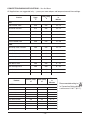
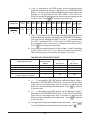
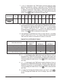
1
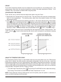
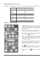
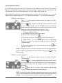
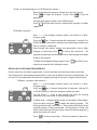
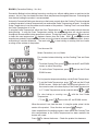
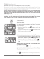
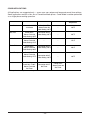
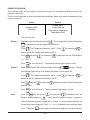
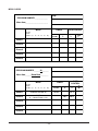
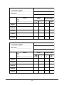
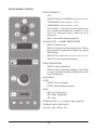
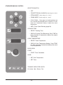
INSTALLATION &
OPERATION MANUAL
GAS COMBI
CONVECTION & STEAM OVENS
MODEL
VCG10H
VCG10F
VCG20H
ML-126836
ML-126837
ML-126838
Model VCG10H
For additional information on Vulcan-Hart or to locate an authorized parts
and service provider in your area, visit our website at www.vulcanhart.com
VULCAN-HART
DIVISION OF ITW FOOD EQUIPMENT GROUP, LLC
WWW.VULCANHART.COM
P.O. BOX 696, LOUISVILLE, KY 40201-0696
TEL. (502) 778-2791
FORM 31188 Rev. A (Sept. 2004)
IMPORTANT FOR YOUR SAFETY
THIS MANUAL HAS BEEN PREPARED FOR PERSONNEL QUALIFIED TO INSTALL GAS
EQUIPMENT, WHO SHOULD PERFORM THE INITIAL FIELD START-UP AND
ADJUSTMENTS OF THE EQUIPMENT COVERED BY THIS MANUAL.
POST IN A PROMINENT LOCATION THE INSTRUCTIONS TO BE FOLLOWED IN THE
EVENT THE SMELL OF GAS IS DETECTED. THIS INFORMATION CAN BE OBTAINED
FROM THE LOCAL GAS SUPPLIER.
IMPORTANT
IN THE EVENT A GAS ODOR IS DETECTED, SHUT DOWN
UNITS AT MAIN SHUTOFF VALVE AND CONTACT THE
LOCAL GAS COMPANY OR GAS SUPPLIER FOR
SERVICE.
FOR YOUR SAFETY
DO NOT STORE OR USE GASOLINE OR OTHER
FLAMMABLE VAPORS OR LIQUIDS IN THE VICINITY OF
THIS OR ANY OTHER APPLIANCE.
WARNING: IMPROPER INSTALLATION, ADJUSTMENT,
ALTERATION, SERVICE OR MAINTENANCE CAN CAUSE
PROPERTY DAMAGE, INJURY OR DEATH. READ THE
INSTALLATION, OPERATING AND MAINTENANCE
INSTRUCTIONS THOROUGHLY BEFORE INSTALLING OR
SERVICING THIS EQUIPMENT.
IN THE EVENT OF A POWER FAILURE, DO NOT
ATTEMPT TO OPERATE THIS DEVICE.
© Vulcan-Hart 2002
–2–
TABLE OF CONTENTS
GENERAL . . . . . . . . . . . . . . . . . . . . . . . . . . . . . . . . . . . . . . . . . . . . . . . . . . . . . . . . . . . . . . . . . . 5
INSTALLATION . . . . . . . . . . . . . . . . . . . . . . . . . . . . . . . . . . . . . . . . . . . . . . . . . . . . . . . . . . . . . . 5
UNPACKING . . . . . . . . . . . . . . . . . . . . . . . . . . . . . . . . . . . . . . . . . . . . . . . . . . . . . . . . . . .
LOCATION . . . . . . . . . . . . . . . . . . . . . . . . . . . . . . . . . . . . . . . . . . . . . . . . . . . . . . . . . . . .
LEGS, CASTERS OR STAND . . . . . . . . . . . . . . . . . . . . . . . . . . . . . . . . . . . . . . . . . . . . .
DRIP TRAY . . . . . . . . . . . . . . . . . . . . . . . . . . . . . . . . . . . . . . . . . . . . . . . . . . . . . . . . . . . .
LEVELING . . . . . . . . . . . . . . . . . . . . . . . . . . . . . . . . . . . . . . . . . . . . . . . . . . . . . . . . . . . . .
DOOR ADJUSTMENT . . . . . . . . . . . . . . . . . . . . . . . . . . . . . . . . . . . . . . . . . . . . . . . . . . .
INSTALLATION CODES AND STANDARDS . . . . . . . . . . . . . . . . . . . . . . . . . . . . . . . . .
VENT HOOD . . . . . . . . . . . . . . . . . . . . . . . . . . . . . . . . . . . . . . . . . . . . . . . . . . . . . . . . . . .
GAS CONNECTION . . . . . . . . . . . . . . . . . . . . . . . . . . . . . . . . . . . . . . . . . . . . . . . . . . . . .
TESTING THE GAS SUPPLY PIPING SYSTEM . . . . . . . . . . . . . . . . . . . . . . . . . . .
PLUMBING CONNECTIONS . . . . . . . . . . . . . . . . . . . . . . . . . . . . . . . . . . . . . . . . . . . . . .
WATER REQUIREMENTS . . . . . . . . . . . . . . . . . . . . . . . . . . . . . . . . . . . . . . . . . . . .
WATER SUPPLY CONNECTIONS . . . . . . . . . . . . . . . . . . . . . . . . . . . . . . . . . . . . . .
DRAIN CONNECTION . . . . . . . . . . . . . . . . . . . . . . . . . . . . . . . . . . . . . . . . . . . . . . . .
ELECTRICAL CONNECTION . . . . . . . . . . . . . . . . . . . . . . . . . . . . . . . . . . . . . . . . . . . . .
START-UP PROCEDURE . . . . . . . . . . . . . . . . . . . . . . . . . . . . . . . . . . . . . . . . . . . . . . . .
CONFIGURE CONTROLS . . . . . . . . . . . . . . . . . . . . . . . . . . . . . . . . . . . . . . . . . . . . . . . .
BEFORE FIRST USE . . . . . . . . . . . . . . . . . . . . . . . . . . . . . . . . . . . . . . . . . . . . . . . . . . . .
5
5
5
6
6
6
6
6
7
7
8
8
8
8
9
9
9
9
OPERATION . . . . . . . . . . . . . . . . . . . . . . . . . . . . . . . . . . . . . . . . . . . . . . . . . . . . . . . . . . . . . . . 10
DOOR OPENING AND CLOSING . . . . . . . . . . . . . . . . . . . . . . . . . . . . . . . . . . . . . . . . .
GREASE FILTER . . . . . . . . . . . . . . . . . . . . . . . . . . . . . . . . . . . . . . . . . . . . . . . . . . . . . .
BUZZER . . . . . . . . . . . . . . . . . . . . . . . . . . . . . . . . . . . . . . . . . . . . . . . . . . . . . . . . . . . . .
LOADING THE OVEN . . . . . . . . . . . . . . . . . . . . . . . . . . . . . . . . . . . . . . . . . . . . . . . . . .
UNLOADING THE OVEN . . . . . . . . . . . . . . . . . . . . . . . . . . . . . . . . . . . . . . . . . . . . . . . .
PROGRAMMABLE CONTROLS . . . . . . . . . . . . . . . . . . . . . . . . . . . . . . . . . . . . . . . . . .
ON — OFF . . . . . . . . . . . . . . . . . . . . . . . . . . . . . . . . . . . . . . . . . . . . . . . . . . . . . . . .
COOKING MODE . . . . . . . . . . . . . . . . . . . . . . . . . . . . . . . . . . . . . . . . . . . . . . . . . . .
COOKING TIME OR PROBE TEMPERATURE . . . . . . . . . . . . . . . . . . . . . . . . . . .
.......................................
OVEN TEMPERATURE OR
PROGRAM NUMBER . . . . . . . . . . . . . . . . . . . . . . . . . . . . . . . . . . . . . . . . . . . . . . .
PROBE . . . . . . . . . . . . . . . . . . . . . . . . . . . . . . . . . . . . . . . . . . . . . . . . . . . . . . . . . . .
COOKING WITH THE PROBE . . . . . . . . . . . . . . . . . . . . . . . . . . . . . . . . . . . . . . . .
USING THE TEMPERATURE PROBE . . . . . . . . . . . . . . . . . . . . . . . . . . . . . . . . . .
TEMPERATURE PROBE APPLICATIONS . . . . . . . . . . . . . . . . . . . . . . . . . . . . . .
ENTERING A COOKING PROGRAM . . . . . . . . . . . . . . . . . . . . . . . . . . . . . . . . . . .
PROGRAMMING MEMORY . . . . . . . . . . . . . . . . . . . . . . . . . . . . . . . . . . . . . . . . . .
–3–
10
10
10
11
11
12
13
13
13
13
13
14
14
14
15
15
16
RECALLING A PROGRAM FROM MEMORY . . . . . . . . . . . . . . . . . . . . . . . . . . . .
BAKING (CONVECTION BAKING - HOT AIR) . . . . . . . . . . . . . . . . . . . . . . . . . . .
CONVECTION BAKING APPLICATIONS . . . . . . . . . . . . . . . . . . . . . . . . . . . . . . .
STEAMING . . . . . . . . . . . . . . . . . . . . . . . . . . . . . . . . . . . . . . . . . . . . . . . . . . . . . . . .
STEAMING APPLICATIONS . . . . . . . . . . . . . . . . . . . . . . . . . . . . . . . . . . . . . . . . . .
COMBI (CONVECTION BAKING WITH STEAMING) . . . . . . . . . . . . . . . . . . . . . .
COMBI APPLICATIONS . . . . . . . . . . . . . . . . . . . . . . . . . . . . . . . . . . . . . . . . . . . . .
EXAMPLE PROGRAM . . . . . . . . . . . . . . . . . . . . . . . . . . . . . . . . . . . . . . . . . . . . . . .
MENU CARDS . . . . . . . . . . . . . . . . . . . . . . . . . . . . . . . . . . . . . . . . . . . . . . . . . . . . .
DELUXE MANUAL CONTROL . . . . . . . . . . . . . . . . . . . . . . . . . . . . . . . . . . . . . . . . . . .
ENTERING A MANUAL COOKING OPERATION — Deluxe Control . . . . . . . . . .
STANDARD MANUAL CONTROL . . . . . . . . . . . . . . . . . . . . . . . . . . . . . . . . . . . . . . . . .
ENTERING A MANUAL COOKING OPERATION — Standard Control . . . . . . . .
CLEANING . . . . . . . . . . . . . . . . . . . . . . . . . . . . . . . . . . . . . . . . . . . . . . . . . . . . . . . . . . .
DAILY CLEANING . . . . . . . . . . . . . . . . . . . . . . . . . . . . . . . . . . . . . . . . . . . . . . . . . .
COMPLETE CLEANING . . . . . . . . . . . . . . . . . . . . . . . . . . . . . . . . . . . . . . . . . . . . .
CONFIGURATION MODE — PROGRAMMABLE CONTROL . . . . . . . . . . . . . . . . . . .
CONFIGURATION MODE — MANUAL CONTROL (Standard or Deluxe) . . . . . . . . .
17
18
19
20
21
22
23
24
25
28
29
30
31
32
32
32
34
36
MAINTENANCE . . . . . . . . . . . . . . . . . . . . . . . . . . . . . . . . . . . . . . . . . . . . . . . . . . . . . . . . . . . . 38
CLEAN CYCLE DELIMING PROCEDURE . . . . . . . . . . . . . . . . . . . . . . . . . . . . . . . . . . 38
TROUBLESHOOTING . . . . . . . . . . . . . . . . . . . . . . . . . . . . . . . . . . . . . . . . . . . . . . . . . . . . . . . 39
SERVICE ADJUSTMENTS . . . . . . . . . . . . . . . . . . . . . . . . . . . . . . . . . . . . . . . . . . . . . . 40
SERVICE AND PARTS INFORMATION . . . . . . . . . . . . . . . . . . . . . . . . . . . . . . . . . . . . 40
–4–
Installation, Operation and Care of
GAS COMBI CONVECTION & STEAM OVENS
KEEP THIS MANUAL FOR FUTURE USE
GENERAL
The Vulcan Combi Gas Convection & Steam Ovens are single compartment ovens that provide
convection heating, steaming or both. Ovens are sized to accommodate 10 or 20 shelves, Full or Half
depth. The bold numbers and letters explain the model number conventions. An atmospheric steam
generator is provided for humidification in the oven chamber. Programmable or analog controls are
preference options on all size and depth combinations.
The 10 level models can be installed on an optional stand or on a suitable countertop using the legs
provided. The 20 level oven can be equipped with legs or casters (optional). Accessory trolleys or
landing tables (depending on size of oven) can load or unload all racks in one easy motion. The hose
spray accessory can be installed near the oven to facilitate easy cleaning. Stacking kits are available
with either legs or casters to stack one 10 level oven on top of another: 10 Half over 10 Full, 10 Full
over 10 Full or 10 Half over 10 Half.
INSTALLATION
UNPACKING
Immediately after unpacking the oven, check for possible shipping damage. If the oven is found to be
damaged, save the packaging material and contact the carrier within 15 days of delivery.
Prior to installation, verify that the electrical service and type of gas (natural or propane) agree with the
specifications on the oven data plate.
LOCATION
Allow space for operating the oven. Do not obstruct the ventilation ports above the oven. Do not install
the oven next to a major heat source, such as a griddle or fryer. All models require a minimum clearance
of 8" on the right side of the oven and 6" at the rear. Model VCG10F requires an 8" clearance on the
left side.
LEGS, CASTERS or STAND
The 10 level gas ovens can be equipped with a leg- or caster-equipped stand. The 20 level gas ovens
can be equipped with legs or casters. Assemble legs or casters into the holes provided at the bottom
four corners of the oven as necessary. To assemble the oven onto the stand, insert four bolts from
underneath at the four corners and tighten until secure.
–5–
DRIP TRAY
Verify that the drip tray is assembled to the bottom of the oven. If it is not, loosen screws under front
of oven base and assemble drip tray to bottom of oven. The 20 level ovens have a drip tray that has
three segments.
LEVELING
Caster equipped ovens must be placed on a level floor. For ovens with legs, use a spirit level or pan
of water in the bottom of the oven to make sure the oven is level, both front-to-back and side-to-side.
Adjust the leveling feet on the bottom of the legs by turning the feet in or out to level the oven. After
the drain is connected, check for level by pouring water onto the floor of the compartment. All water
should drain through the drain opening.
DOOR ADJUSTMENT
One door roller is located in the middle of the door on 10 level ovens; two rollers, one at the top and
the other at the bottom, are located on the door of the 20 level oven. The rollers can be adjusted by
loosening the screws above and below the roller. Adjust the roller to the best vertical position and
tighten the screws.
INSTALLATION CODES AND STANDARDS
In the United States, install the oven in accordance with: 1) State and local codes; 2) National Fuel
Gas Code, ANSI-Z223.1, latest edition, available from American Gas Association, 1515 Wilson
Boulevard, Arlington, VA 22209; 3) National Electrical Code, ANSI/NFPA No. 70, latest edition; and
4) NFPA Standard #96, Vapor Removal from Cooking Equipment, latest edition, available from the
National Fire Protection Association, Batterymarch Park, Quincy, MA 02269.
In Canada, install the oven in accordance with: 1) Local codes; 2) CAN/CGA-B149.1, Installation for
Natural Gas Burning Appliances and Equipment, latest edition; 3) CAN/CGA-B149.2, Installation for
Propane Burning Appliances and Equipment, latest edition; and, 4) Canadian Electrical Code, Part 1,
CSA Standard C22.1, latest edition.
VENT HOOD
The Combi oven should be located under a suitable exhaust hood to vent steam, smoke, grease laden
vapors, etc. Information on the construction and installation of ventilating hoods may be obtained from
Vapor Removal from Cooking Equipment, NFPA standard No. 96 (latest edition).
–6–
GAS INPUT
Burner Input Rating
Model
VCG10H
VCG10F
VCG20H
Gas Type
Gas Pressure
Oven
Steam Generator
Total
Convection
Steam
Natural
67,000 BTU/Hr
40,000 BTU/Hr
107,000 BTU/Hr
3.5" W.C.
3.5" W.C.
Propane
69,000 BTU/Hr
40,000 BTU/Hr
109,000 BTU/Hr
10.0" W.C.
10.0" W.C.
Natural
85,000 BTU/Hr
45,000 BTU/Hr
130,000 BTU/Hr
3.5" W.C.
3.5" W.C.
Propane
85,000 BTU/Hr
45,000 BTU/Hr
130,000 BTU/Hr
10.0" W.C.
10.0" W.C.
Natural
70,000 BTU/Hr
58,000 BTU/Hr
128,000 BTU/Hr
3.5" W.C.
3.5" W.C.
Propane
70,000 BTU/Hr
58,000 BTU/Hr
128,000 BTU/Hr
8.0" W.C.
10.0" W.C.
GAS CONNECTION
All gas supply connections and any pipe joint compound must be resistant to the action of propane
gases. The machine connection is 3/4" external thread. A manual valve (supplied) must be installed
in the gas supply line ahead of the appliance. Make sure piping is clean and free of obstructions, dirt
or pipe joint compound. Recommended gas supply pressures are 7" W.C. (Water Column) for natural
gas and 11" W.C. for propane. The gas line must be capable of delivering gas to the oven without
excessive pressure drop at the rate specified on the rating plate.
The oven is equipped with a factory preset pressure regulator. Natural gas pressure regulators are
preset for 3.5" W.C. for both ovens and steam generators. Propane gas pressure regulators for 10 level
ovens are preset for 10" W.C. for both the oven and steam generator. Propane gas pressure regulators
for 20 level half depth ovens are preset for 8" W.C. for the oven burner and 10" W.C. for the steam
generator. Gas pressure must be checked for correct operating pressure at start-up.
Caster equipped ovens must be installed with a connector that complies with the Standard for
Connectors for Movable Gas Appliances, ANSI-Z21.69 (latest edition) [in Canada, CAN/CGA-6.16,
latest edition] and a quick-disconnect device that complies with the Standard for Quick-Disconnect
Devices for Use with Gas Fuel, ANSI-Z21.41 (latest edition) [in Canada, CAN 1-6.9, latest edition]. A
gas line strain relief must be provided to limit the movement of the oven without depending on the
connector and the quick-disconnect device or its associated piping to limit oven movement. Attach the
strain relief to the rear of the oven at the location provided. If it is necessary to disconnect the restraint
during service or maintenance, first turn off the gas supply. Reconnect the restraint before returning
the oven to its original installed location and turning the gas supply on.
WARNING: PRIOR TO LIGHTING, CHECK ALL JOINTS IN THE GAS SUPPLY LINE FOR LEAKS.
USE SOAP AND WATER SOLUTION. DO NOT USE AN OPEN FLAME.
The convection burner and the steam generator burner are ignited automatically by electric igniters;
there are no pilot lights. See Start-Up Procedure, page 9.
Keep the appliance area free and clear from all combustible substances. Do not obstruct the flow of
combustion and ventilation air. Make sure there is an adequate supply of air in the room to allow for
combustion at the burners and exhaust by the vent hood system.
Testing the Gas Supply Piping System
When test pressures exceed 1/2 psig (3.45 kPa), the oven and its individual shutoff valve must be
disconnected from the gas supply piping system.
When test pressures are 1/2 psig (3.45 kPa) or less, the oven must be isolated from the gas supply piping
system by closing its individual shutoff valve.
–7–
PLUMBING CONNECTIONS
WARNING: PLUMBING CONNECTIONS MUST COMPLY WITH APPLICABLE SANITARY, SAFETY
AND PLUMBING CODES.
WATER REQUIREMENTS
Supply Pressure
Hardness*
Silica
Total Chlorine
pH range
Undissolved Solids
Water Requirements
Proper water quality can improve the taste of the
food prepared in the steamer, reduce liming in the
steam generator and extend equipment life. Local
water conditions vary from one location to another.
Ask your municipal water supplier for details about
your local water supply prior to installation.
*
20 — 60 psig
less than 3 grains
less than 13 ppm
less than 4.0 ppm
7—8
less than 5 microns
17.1 ppm = 1 grain of hardness
Presence of sediment, silica, excess chlorides or other dissolved solids may lead to a recommendation
for alternate form(s) of water treatment. Test the water with the test strip included with the combi oven.
Other factors affecting steam generation are iron content, amount of chloridation and dissolved gases.
A local water treatment specialist should be consulted before installation of steam generating
equipment.
Water Supply Connections (Fig. 2)
A water filter system is recommended for the water supply line going to the treated water inlet of your
oven. Follow the recommendations for use and installation instructions shipped with the water filter.
If a water filter is not installed, the oven warranty may be limited.
Connect treated potable water ( must be cold) to the inlet labeled for treated water to supply the steam
generator tank. Untreated water contains scale producing minerals which, if supplied to the steam
generator, can precipitate onto the surfaces in the steam generator tank. Due to the temperatures in
the tank, the minerals can bake onto the surfaces and components. This can result in early component
failure and reduced product life. Sensors in the steam generator tank use ions in the water to detect
the water level. Do not use distilled (fully demineralized or de-ionized) water as this could provide a
false reading to the sensors. Strainers and filters will NOT remove minerals from the water.
Connect untreated potable water (must be cold) to the inlet labeled for
untreated water to supply the condenser which cools the drain water.
Both external-threaded nylon inlets 3/4" hose bibb (3/4" NSHT, National
Straight Hose Thread) are located at the rear of the oven. The nylon threads
should be treated carefully so the connections do not leak. A manual shutoff
valve should be provided, convenient to the oven, for each water supply line;
both of these valves should be open when the oven is in operation. Water
pressure for both incoming water lines should be between 20 and 60 psig.
Refer also to CLEAN CYCLE DELIMING PROCEDURE, page 38.
Water Supply Inlets . . .
at Bottom Rear Corner of Oven
. . . Model VCG10H Shown.
TREATED WATER
UNTREATED WATER
GAS SUPPLY
ELECTRIC SUPPLY CORD
Fig. 2
Drain Connection
CAUTION: In order to avoid any back pressure in the oven, do not connect solidly to any drain
connection.
The drain connection, 11/2" NPT threaded fitting, is located underneath the oven at the rear. The drain
line must be plumbed to an open gap-type drain. Drain piping must have suitable pitch, have
appropriate support along its length and have no connection to other piping. The material used in the
drain line should be heat resistant to at least 212°F. The open drain should be located between 3 and
5 feet away from the perimeter of the oven to reduce potential damage from moisture-corrosion. The
drain line from the oven must not be combined with any drain line from another device.
–8–
ELECTRICAL CONNECTION — Cord Connected Ovens
WARNING: ELECTRICAL AND GROUNDING CONNECTIONS MUST COMPLY WITH THE
APPLICABLE PORTIONS OF THE NATIONAL ELECTRICAL CODE AND/OR OTHER LOCAL
ELECTRICAL CODES.
WARNING: THE SUPPLY CORD ON THIS OVEN IS PROVIDED WITH A GROUNDING PLUG.
THE OUTLET TO WHICH THIS PLUG IS CONNECTED MUST BE PROPERLY GROUNDED. IF
THE RECEPTACLE IS NOT THE PROPER GROUNDING TYPE, CONTACT AN ELECTRICIAN.
The wiring diagram is located on the inside surface of the right side panel as you face the oven.
START-UP PROCEDURE
The Gas Combi Ovens are equipped with a gas burner for convection heating and a gas steam
generator for atmospheric steaming; two independent flues exhaust the burnt gases. Become familiar
with the entire manual before continuing with this Start-Up Procedure. Remove the tray rack, grease
filter and fan baffle from the oven cavity. Turn gas and water on. Press the ON button.
four times (four
• Select Combi Mode and adjust the steam time to 50% by pressing
indicator lights are lit).
• Leave oven temp setting at 302°F and the timer display blank, [-]h [--]min.
• Close the oven door and press the Start Button. The oven convection fan rotates counterclockwise.
The oven flue vent should be open.
• After a delay of 50 seconds while the oven adjusts for Combi Mode, the sparker on the left side of
the burner should ignite the Convection Burner. Observe blue flame. On some units, the Convection
Burner ignites for an instant, goes off and then comes back on (while the flame sensor is tested).
On other units without the double ignition sequence, the Convection Burner may ignite and stay on.
After an additional 70 seconds, the steam generator flame should ignite. Observe blue flame
through window below controls.
, will be lit.
If the Convection Burner does not ignite, the NO Convection Burner indicator light,
• Wait 30 seconds until the
light starts to flash and the buzzer sounds.
indicator light.
• Reset the Convection Burner by pressing the Reset Button above the
• This procedure may need to be repeated several times until all of the air in the pipeline is replaced
by gas. The longer the pipe, the longer it will take to remove the air from the pipe.
, will be lit.
If the Steam Generator Burner does not ignite, the NO Steam Burner indicator light,
• Wait 10 seconds until the
light starts to flash and the buzzer sounds.
• Reset the Steam Generator Burner by pressing the Reset Button above the
indicator light.
• This procedure may need to be repeated several times until all of the air in the pipeline is replaced
by gas.
If a make-up air system is part of the vent hood, make sure there is no down-draft pushing hot
combustion gases from the flues back into the oven.
Press OFF and observe that the pump drains the steam generator for about one minute. The door will
open. After the oven is cool, reinstall fan baffle, grease filter and tray rack.
CONFIGURE CONTROLS
Depending on which control is furnished, perform CONFIGURATION MODE — PROGRAMMABLE
CONTROL on pages 34 – 35 or CONFIGURATION MODE — MANUAL CONTROL on pages 36 – 37.
BEFORE FIRST USE
Before using the oven for the first time, it must be "burned in" to release any odors that might result from
heating the new surfaces in the oven. Operate the oven at 480°F for 45 minutes in Convection HOT
AIR Mode.
–9–
OPERATION
WARNING: THE OVEN AND ITS PARTS ARE HOT. USE CARE WHEN OPERATING, CLEANING
OR SERVICING THE OVEN. THE COOKING COMPARTMENT CONTAINS LIVE STEAM. STAY
CLEAR WHEN OPENING DOOR.
DOOR OPENING AND CLOSING
The oven door is equipped with an electrically powered lock. The oven is delivered with the door
latched and slightly open (Fig. 3) and can be opened by firmly pulling the door handle (Fig. 5). Push
the door until it connects with the latch but remains slightly open (Fig. 3). This is the position the door
should be in when the oven is not in use. The door should also be in this position after cooking to allow
steam to escape before fully opening the door. Push the handle until it is in line with the oven door.
If power has been connected, the door will now lock automatically, sealing the oven chamber (Fig. 4).
To release the door, rotate (pull) the handle 90 degrees. The door automatically releases to the
"latched and slightly open" position. Allow a few seconds for steam to escape before pulling the door
open (Fig. 5).
NOTE: On Programmable Controls if the ON button is pushed after the oven is turned on, the door will
be latched but slightly open (Fig. 3) for three seconds; the handle can be released by rotating
90 degrees as shown in Fig. 5. If the handle is not released within the three second interval, the door
will automatically re-close. A separate Door Open button will perform the same function with Manual
Standard or Deluxe Controls. On stacked ovens, the lower oven's handle does not rotate. To open,
press the ON button. When the door opens (Fig. 3), pull the metal handle located on the top of the door
to fully open the oven door.
→
Fig. 3
Fig. 4
Fig. 5
NOTE: In the event of a power failure, the door may be opened by pulling the handle firmly towards
you while firmly pressing against the front of the oven with the other hand (avoid hot air contact).
GREASE FILTER
The grease filter in the rear of the oven chamber should be in place when roasting meat items but may
be removed before baking items that do not produce grease-laden vapors. For information on how to
remove the grease filter, refer to Cleaning (page 32).
BUZZER
When either the Cooking Time has elapsed or the final internal Probe Temperature has been reached,
is pressed. If done, the product should be removed, portioned and
the buzzer will sound until
served. The Buzzer can be adjusted two ways: Buzzer loudness can be adjusted by your service
technician. Buzzer frequency can be set in Configuration Mode for the type of control furnished with
your oven (refer to either page 34 or 36).
– 10 –
LOADING THE OVEN
Open the door. Place the product to be cooked in
suitable containers and slide into the racks or place
the containers securely on shelves in the oven.
When loading a 10 level oven with the landing table
(Fig. 6), the bottom frame of the rack should be
secured by the rotary lock. Move the loaded landing
table to the front of the open oven; secure the
landing table to the oven by actuating the locking
clamp (or use your body to hold the landing table
against the oven). Rotate the lock-knob to release
the pan rack and carefully roll the loaded pan rack
into the oven while making sure that the landing
table does not separate from the oven during the
transfer.
NOTE: When the landing table is not in use on the
10 level oven, make sure the rack retainer (delivered
with the oven) is fitted under the fan baffle to
prevent the pan rack from tilting when pans are
being removed.
Fig. 6
When loading a 20 level oven with the trolley (Fig. 7), make sure the handle is locked in the down
position so the rack is held securely to the trolley with its lifting hooks. Carefully move the loaded trolley
completely into the open oven. When the rear frame of the rack is positioned behind the edge of the
retainer, raise the handle to lower the rack-frame to the oven door.
UNLOADING THE OVEN
Allow the door to be slightly-opened for a few seconds to allow hot air and steam to escape. Stand
behind the door while opening.
When unloading a 10 level oven, move the landing
table so the clamp locks the landing table to the
front of the oven (or use your body to hold the
landing table against the oven). Remove the landing
table handles and clamp them to the bottom of the
hot oven pan rack. Carefully roll the hot pan rack
onto the landing table platform while making sure
that the landing table does not separate from the
oven during transfer. Rotate the knob to allow the
rack to move completely to the front of the landing
table; and rotate the knob back to lock the pan rack
in place.
When unloading a 20 level oven, move the trolley
(Fig. 7) into the oven until the "lift-hooks" are inserted
into both sides of the front frame of the rack in the
correct "lift" position. Lower the trolley handle until
it stops; the loaded rack is lifted from its retainer and
held securely to the trolley by the "lift-hooks". The
trolley may now be removed from the oven with the
loaded rack securely held in place.
– 11 –
Fig. 7
PROGRAMMABLE CONTROLS
ON
DOOR
ON OFF
See Door Opening and Closing, page 10.
OFF
ON
COOKING MODE
• HOT AIR (Convection Baking)1
• STEAM1
HOT AIR
STEAM
2
2
COMBI
• COMBI (Convection & Steam)1
START STOP1
2
PHASE 1 – 5
COOKING TIME1 or PROBE TEMPERATURE1
h
min
• SET Cooking Time
• DISPLAY Cooking Time, remaining
• SET Probe Temperature, final
TIME
DOWN
UP
PROBE
• DISPLAY Probe Temperature, actual
OVEN TEMPERATURE or
1
• SET Oven Temperature, desired
• DISPLAY Oven Temperature, actual
• SET
TEMP
DOWN
and use with Probe Temperature
UP
PROGRAM NUMBER
• SET Cooking Programs
• RECALL or CHANGE a Cooking Program
• ENTER [
ENTER
DOWN
] to save the Cooking Program
UP
HCPC
RESET (Left Button: Air Intake or Convection Burner)
RESET
RESET
RESET (Right Button: Steam Generator or Fan)
TROUBLE INDICATOR LIGHTS
Air Intake, Heat, Steam, Fan (refer to page 39).
1
Upper indicator light shows the Mode selected.
2
Lower indicator light means the burner is ON.
– 12 –
ON
— After an initial power-up sequence, the control panel indicator lights and the light
inside the oven are lit. The actual oven temperature is shown in the Temperature
display, – h – – min is in the Time display, and – – is in the Program Number display.
The control will now accept commands. The ON button also cancels a manual
cooking operation of up to 5 Phases. (Pressing the ON button while the oven is
running will open the door. Refer to page 10.)
OFF
— Shuts off the oven and oven light, opens the oven vent and drains the steam
generator tank (pump takes about a minute).
COOKING MODE
HOT AIR — Heat and Fan are ON; steam generator tank fills. Initial temperature setting is 302°F
(range is 35 – 518°F).
STEAM
— Steam and Fan are ON; steam generator tank fills, if not already full. Initial
temperature setting is 212°F (range is 35 – 212°F) depending on the configuration
setting for your altitude (refer to either page 35 or page 37).
COMBI
— Heat, Fan and Steam are ON; steam generator tank fills, if not already full. Initial
temperature setting is 302°F (range is 35 – 518°F). The amount of steaming is set
by the number of times you press the Combi key (1 – 6), indicated by the row of lights.
START STOP— Starts or stops a cooking operation. Temperature flashes if door is not locked.
PHASE 1–5 — Indicates the Phase of a cooking program. Allows you to step through and display
the cooking information for each phase of a cooking operation before starting.
COOKING TIME or PROBE TEMPERATURE
TIME
— Displays the Cooking Time. Time remaining for ALL phases is normally displayed.
Press the Time key again to display the time remaining for the current phase. When
[ – h – – min ] displays in the time display, the oven is in manual mode (does not
switch oven off at end of cycle).
DOWN
— Decreases the Cooking Time or Probe Temperature setting.
UP
— Increases the Cooking Time or Probe Temperature setting.
PROBE
— Displays the Probe Temperature setting, initially 140°F (range is 70 – 210°F). After
5 seconds, displays the actual Probe Temperature.
OVEN TEMPERATURE or
TEMP
— Displays the Oven Temp instead of
. Normally displays the actual Oven Temp.
Press Temp to display the Oven Temperature setting for 5 seconds and adjust it.
DOWN
— Decreases the Oven Temperature or
UP
— Increases the Oven Temperature or
setting.
setting.
— Displays
instead of Oven Temperature (temperature difference is indicated by
keeps the oven
degrees warmer than the actual Probe
__t in the display).
must be used with the Probe Temperature.
Temperature.
PROGRAM NUMBER
PROG.
— Recalls and displays the cooking programs, by number, beginning with 00.
DOWN
— Decreases the Program Number (range is 00 to 98).
UP
— Increases the Program Number (range is 00 to 98).
ENTER
— Stores the cooking parameters (up to 5 Phases) in memory under the Program
Number. Cooking parameters will not be lost during power outage or disconnection.
– 13 –
PROBE
The Probe Temperature defines the final temperature of the product for any cooking phase. The
cooking cycle stops when the product temperature reaches the probe temperature setting. Total
Cooking Time is not known or entered when using the probe.
COOKING WITH THE PROBE
There are two ways to control the oven temperature when using the Probe . . .
1) Setting the Oven Temperature at a constant value. The oven climbs to the set point and the product
cooks at that temperature. The cooking cycle ends when the product reaches the Probe
temperature setting.
, the Oven temperature gradually increases as the internal temperature of the product
2) Using
degrees warmer than the product.
can provide
increases, always maintaining the oven at
a slow cooking process that allows the product's required final internal temperature to be reached
without over-browning the outside of the product. The Probe Temperature (not cooking Time) must
. For Hot Air or Combi Modes, the recommended minimum
is 110 F°;
be used when using
is 60 F°; maximum is 180 F°.
maximum is 240 F°. For Steam Mode, the recommended minimum
The graph, below, shows two ways of controlling the oven temperature when using the Probe. The
is used to show how the oven works and is not typical of any particular cooking
150 F° value for
program.
USING THE TEMPERATURE PROBE
The Temperature Probe is kept in a metal holder at the top of the oven when not in use. Remove the
probe from its holder; the cable remains permanently connected to the top of the oven. Insert the
pointed end of the probe so its tip is approximately in the middle of the product to be cooked. The probe
cable is long enough to allow the product to be placed on one of the upper racks in the oven. The probe
can be used to define the final temperature for any phase of the cooking process and for any of the three
cooking modes: Convection (Hot Air), Steam or Combi.
• To set the Probe Temperature, press
and use the UP and DOWN arrows to adjust the setting.
The Cooking Time cannot be used when the Probe Temperature is in use.
NOTE: During Operator training to demonstrate use of the probe, place the probe in a container of
water to simulate cooking of actual product.
– 14 –
TEMPERATURE PROBE APPLICATIONS
All Applications are suggested only — prove your own recipes and temperature and time settings.
Recommended Final Probe Temperature
O
F
Product
Beef
Rare
Medium
Well Done
125
140
180
Lamb
140 – 165
Pork
Fresh
Smoked
175
140 – 175
Turkey
Whole
Boneless
185
175
Veal
145 – 165
ENTERING A COOKING PROGRAM
HOT AIR
STEAM
1. When entering cooking parameters, always select
the Mode as the first element in a cooking phase:
HOT AIR, STEAM or COMBI (also select Steam Factor
for COMBI mode).
COMBI
2. Enter the finish parameter for the cooking phase
(COOKING TIME or PROBE TEMP) with its value.
h
TIME
DOWN
min
UP
PROBE
3. Enter the oven control parameter for the cooking
) with its value.
phase (TEMP or
4. Steps 1, 2 and 3 complete the parameters for that
phase. For any additional phase (or phases), press
the PHASE 1 – 5 key. Repeat steps 1, 2, 3 and 4
for each cooking phase.
5. If programming a repeat cooking process, select a
Program Number following the instructions for
Programming Memory on the next two pages.
TEMP
DOWN
UP
to start cooking; the indicator light in the
6. Press
Start Stop key indicates the oven is operational.
7. When finished, press
buzzer.
ENTER
DOWN
UP
– 15 –
again to silence the
PROGRAMMING MEMORY
Up to 99 Cooking Programs with up to 5 Phases in each program can be keyed-in and stored in
Memory. Each program is accessed by its identifying number. Program numbers range from 00 – 98.
A pre-defined Clean Cycle Deliming program is also available (refer to page 38).
If the numbered Program has not been programmed (or is vacant), the Time displays – h – – min. No
Mode or Phase indicator lights are lit. The Temperature displays – – or the current temperature.
To CREATE a new program —
With — — in the program number display, the control is in NonProgram mode.
00
——
ENTER
DOWN
key. Program Number 00 is displayed and the control
Press the
is now in Program Mode. Use UP or DOWN arrows to increase or
decrease the program number until a vacant program number is found.
UP
ENTER
THE COOKING INSTRUCTIONS ( FOLLOW STEPS
1 – 6):
1) Select the cooking mode: Hot Air, Steam or Combi.
If Combi, set Steam Factor.
2) Set either the Time or Probe Temperature.
.
3) Set the Oven Temperature or
4) End of the 1st Phase. Press
to shift to the next phase.
5) Repeat steps 1 – 4 for as many of the 5 phases as are needed.
Review the program by stepping through the phases. Make any
needed changes.
6) When the program is set, save it in memory by pressing
the beep is heard.
until
NOTE: A cooking program can also be entered in manual mode and saved to a
program number by selecting the Program Number and pressing
for about
three seconds.
To DELETE an existing program —
With — — in the program number display, the control is in NonProgram mode.
00
key. Program Number 00 is displayed and the control
Press the
is in Program Mode. Use UP or DOWN arrows to increase or decrease
the program number until the program number to be deleted is
displayed.
——
ENTER
DOWN
UP
Press
and hold it in for about three seconds until the beep
sounds, indicating the program has been deleted.
NOTE: If a previous program had been selected and was active in Non-Program
mode, it will be copied to the selected program number, replacing the previous
program. Verify that the program number is vacant after you delete it.
– 16 –
To COPY an existing program to a NEW program number —
Recall and display the program number that you wish to copy.
Press
to begin the program. Pause. Press
to stop the
program.
Change the program number to the NEW number.
Press
until the beep sounds, indicating the program has been
copied.
To CHANGE a program —
With — — in the program number display, the control is in NonProgram mode.
Press the
key. Program number 00 is displayed. Use the UP or
DOWN arrows to increase or decrease until the program number you
want to change is displayed.
Step through each phase, making any temperature, time or other
00
——
ENTER
DOWN
UP
changes for the phase; press
to shift to the next phase. The
program number begins to blink when one or more changes have been
made to the program.
To SAVE the changed cooking program, press
about three seconds until the beep sounds.
and hold it in for
RECALLING A PROGRAM FROM MEMORY
Once a menu item has been programmed, it can be recalled, reviewed and used to cook food.
If the Program has already been programmed, its values are recalled from memory and displayed. You
can view all the programmed information by stepping through the phases using the phase button.
To RECALL a program from memory —
With — — in the program number display, the control is in NonProgram mode.
00
key. Program Number 00 is displayed. Use the UP
Press the
or DOWN arrows to select the program number you want.
——
ENTER
DOWN
Use the Phase 1 – 5 key to step through and verify the cooking
parameters for each phase of the cooking program.
UP
Load the oven. If using the probe, place it in the center of the product.
to begin the cooking program. The
Close the door and press
blinking indicator light in the Phase 1 – 5 key shows which phase of the
cooking program is being performed. If the program is timed, the
display shows the total time remaining. When the cooking program is
done, the buzzer will sound.
Press
to silence the buzzer. Check the product for doneness.
– 17 –
BAKING (Convection Baking – HOT AIR)
Convection Baking involves baking, browning, roasting, etc. without adding steam or moisture to the
process. Hot air is fan-circulated to maintain even temperatures throughout the oven. Preheating the
oven before loading the product is recommended.
Automatic Convection Baking can be set up so the buzzer sounds when the Cooking Time has elapsed
or when the product's internal temperature has reached the Probe Temperature set point. If using the
Probe Temperature, insert the probe near the center of the product. Cooking Time is not used when
the Probe Temperature is in use.
can be used to control the oven
If using the Probe Temperature, either the Oven Temperature or
during baking. If using the Oven Temperature setting, the oven temperature will remain constant
can be set
throughout the convection baking operation or phase. If using the Probe Temperature,
degrees warmer than the Probe. With
cooking, the oven
to keep the oven temperature
temperature gradually increases at the same rate as the internal temperature of the product, always
is slow baking or roasting with less brown
maintaining a constant difference. The result with
crusting on the outside of the product.
Turn the oven ON.
Select Convection (HOT
1
TIME
h
DOWN
35
Mode.
For standard automatic baking, set the Cooking Time and Oven
Temp.
0 5 min
UP
AIR)
• To set the Cooking Time, press
arrows to adjust the setting.
PROBE
and use the UP and DOWN
• To set the Oven Temperature, press
and use the UP and
DOWN arrows.
0• F
For final product temperature baking, set the Probe Temperature.
TEMP
DOWN
and use the UP and
• To set the Probe Temperature, press
DOWN arrows. When the Probe Temperature indicator is lit,
the numeric value in the time display is the Probe Temperature
in °F. Probe Temperature can be used with either
or
.
UP
1 h 7 5 min
TIME
DOWN
UP
PROBE
For slow baking or roasting , use
Temperature.
• To set
, press
with the final Probe
and use the UP and DOWN arrows.
When the control is set, load the oven. If using the probe, place it in the
center of the product. Close the door and press
to begin.
Upon completion of the baking process, when either the Cooking Time
has counted down or the Probe Temperature has been reached, the
buzzer will sound.
Press
to silence the buzzer. Check the product for doneness.
– 18 –
CONVECTION BAKING APPLICATIONS – HOT AIR MODE
All Applications are suggested only — prove your own recipes and temperature and time settings.
Preheat
Temp
O
F
Oven Temp
O
F
Time
in
Minutes
Cod or Mullet, fresh
350
325
10 – 12
Sea-frozen fish fillet
375
325
10 – 12
Sole, fresh
375
325
10 – 12
Trout, fresh
375
325
10 – 12
Trout, frozen
375
325
15 – 22
Trout, breaded, fresh
390
375
15 – 20
Pork Chop, fresh, sauteed
400
325
10 – 12
Pork Chop, frozen, sauteed
400
350
15
Pork Cutlet, fresh, 4 - 5 oz
400
350
10 – 12
Pork Cutlet, fresh, breaded
375
325
10 – 12
Pork Loin Cutlet, fresh 4 - 5 oz
400
350
6–8
Ham Steak, fresh
400
325
6 – 10
Pork Sausage, fresh
400
350
8 – 10
Pork Steak, fresh
400
375
7
Pork Steak, frozen
400
375
10 – 12
Product
FISH
PORK
Product
Preheat Temp
O
F
Oven Temp
O
F
Time
in
Minutes
PASTRY
Puff Pastry
400
350
20
Danish Pastry
350
325
18 – 20
Flaky Pastry
350
325
16 – 18
Cake
350
325
8
Fruit Cake
350
300
55 – 65
Yeast Rolls with milk
350
325
10 – 12
Almond Pastry
350
325
10 – 12
Nut Pastry
350
325
10 – 12
Chocolate Pastry
350
300
10 – 12
Biscuit Pastry
350
325
10 – 12
– 19 –
Recommended setting for
in Convection Baking Mode is
a minimum of 110 F° (61 C°).
STEAMING (Steam Mode only)
Steam Mode will not begin if cavity temperature is above 212°F (100°C).
Steam cooking is used for stewing, poaching and gentle cooking of products cooked in water. Steam
flows without pressure into the oven. The fan circulates the steam to all parts of the oven. Allow the
steam generator to preheat for 4 to 5 minutes if starting from cold.
Automatic Steaming can be set up so the buzzer sounds when the Cooking Time has elapsed or when
the product's internal temperature has reached the Probe Temperature set point. If using the Probe
Temperature, insert the probe near the center of the product. Cooking Time is not used when the Probe
Temperature is in use.
Usually, the Cooking Time and Oven Temperature are used to control the steaming process.
Alternatively, the Probe Temperature can be used to indicate when cooking is done. When using the
can be used to control the oven.
Probe Temperature, either the Oven Temperature or
Turn the oven ON.
Select Steam Mode.
h
TIME
DOWN
21
TEMP
DOWN
10
UP
For standard automatic steaming, set the Cooking Time and the
Oven Temperature.
min
PROBE
• To set the Cooking Time, press
DOWN arrows.
• To set the Oven Temperature, press
2 •F
and use the UP and
and use the UP and
DOWN arrows to adjust the setting.
UP
For final product temperature steaming, set the Probe Temperature.
1 h 7 0 min
and use the UP and
• To set the Probe Temperature, press
DOWN arrows. When the Probe Temperature indicator is lit,
the numeric value in the time display is the Probe Temperature
in °F. Probe Temperature can be used with either
or
.
TIME
DOWN
UP
PROBE
When the control is set, load the oven. If using the probe, place it
in the center of the product.
Close the door and press
to begin.
Upon completion of the steaming process, when either the Cooking
Time has counted down or the Probe Temperature has been
reached, the buzzer will sound.
Press
to silence the buzzer. Check the product for doneness.
– 20 –
STEAMING APPLICATIONS
All Applications are suggested only — prove your own recipes and temperature and time settings.
Time
in
Minutes
Product
VEGETABLES
Asparagus, fresh
4–6
Broccoli, fresh
4–6
Brussels Sprouts, fresh or frozen
6–8
Cabbage, white, sliced, fresh
6–8
Carrots, small, fresh or frozen
6–8
Carrots, diced, fresh
6–8
Cauliflower, fresh
4–6
Cauliflower, head, fresh
4–6
Celery, slices or diced
6–8
Corn, on-the-cob, fresh
15 – 18
Eggplant
6–8
Green Beans, fresh or frozen
4–6
Mushrooms, halved, quartered or sliced
4–6
Peas, frozen
6–8
Potatoes
Spinach, fresh
20 – 35
2
SIDE DISHES
Dumplings, Meat Balls
10 – 20
Rice
20 – 25
MEAT
Brisket
90 – 120
Veal, fricassee
40 – 50
FISH & CRUSTACEANS
Cod, Halibut, fresh
8 – 14
Crayfish Tails, frozen
9 – 14
Mussels
8 – 14
Salmon, fresh
6 – 12
Recommended setting for
in Steam Mode is a minimum of 60 F° (33 C°).
– 21 –
COMBI (Convection Baking with Steam)
Combi baking with steam is used for baking, roasting or braising when steam needs to be added to the
oven during a convection baking operation. The Steam Factor can be varied by repeat pressing of the
Combi key — see Steam Factor in the table below. It is recommended that you preheat the oven.
Automatic Combi baking with steam can be set up so the buzzer sounds when the Cooking Time has
elapsed or when the product's internal temperature has reached the Probe Temperature set point. If
using the Probe Temperature, insert the probe near the center of the product. Cooking Time is not used
when the Probe Temperature is in use.
Usually, the Cooking Time and Oven Temperature are used to control Combi baking with steam.
Alternatively, the Probe Temperature can be used to indicate when cooking is done. When using the
can be used to control the oven.
Probe Temperature, either the Oven Temperature or
Turn the oven ON.
Select Combi Mode and set the Steam Factor (see table below).*
For standard automatic Combi baking with steaming, set the Oven
Temperature and the Cooking Time.
1
TIME
h
DOWN
35
UP
• To set the Cooking Time, press
arrows.
min
PROBE
3 2 5• F
and use the UP and DOWN
• To set the Oven Temperature, press
DOWN arrows to adjust the setting.
For final probe temperature Combi baking with steaming, set the
Probe Temperature.
• To set the Probe Temperature, press
TEMP
DOWN
1
h
and use the UP and
DOWN arrows. When the Probe Temperature indicator is lit, the
numeric value in the time display is the Probe Temperature in °F.
UP
70
and use the UP and
Probe Temperature can be used with either
min
or
.
When the control is set, load the oven. If using the probe, place it
TIME
DOWN
UP
PROBE
in the center of the product. Close the door and press
to begin.
Upon completion of the Combi baking with steaming process, when
either the Cooking Time has counted down or the Probe Temperature
has been reached, the buzzer will sound.
Press
to silence the buzzer. Check the product for doneness.
* When selecting Steam Factor, press
Indicator Lights
❍●●●●●
❍❍●●●●
❍❍❍●●●
1 to 6 times to obtain the desired steaming.
Combi Key
Steam Factor
Pre-selected.
Press one time.
20
30
Press two times.
40
❍❍❍❍●●
❍❍❍❍❍●
Press three times.
Press four times.
50
60
❍❍❍❍❍❍
Press five times.
70
– 22 –
COMBI APPLICATIONS
All Applications are suggested only — prove your own recipes and temperature and time settings.
Some applications contain a HOT AIR or Convection Mode phase. Combi Mode is seldom performed
as a single phase cooking operation.
Product
Roast Beef
Meat Loaf
Pork Loin
Whole Chicken
Whole Turkey
Breads
Phase 1
Phase 2
Phase 3
Final Internal
Temperature
Convection 425 OF
10 minutes
Combi 280OF
Steam Factor 50
Probe Setting 140 oF
–
140OF
Convection 350 OF
Combi 260OF
Steam Factor 40
Probe Setting 165 oF
o
Probe Setting 150 F
–
165OF
Combi 280OF
Steam Factor 40
Probe Setting 175 oF
–
175OF
–
185OF
Convection 350 OF
Probe Setting 190 oF
–
190OF
Convection 325 OF
Set Timer
Combi 375OF
Steam Factor 40
Set Timer
–
Convection 350 OF
Combi 280OF
Steam Factor 40
Probe Setting 185 oF
o
Probe Setting 160 F
Combi 260OF
Steam Factor 40
Probe Setting 175 oF
Proofing:
Combi 90 —100OF
Steam Factor 60
Set Timer
* Always insert a cold probe into the product.
– 23 –
EXAMPLE PROGRAM
This example shows how to program a two-phase process for cooking Roast Beef and store it as
program number 20.
The first item in the table on page 23 provides the information: Refer to the menu card example at the
bottom of page 25.
Phase 1
Phase 2
COMBI 280 OF
Steam Factor 50
Convection 425OF
10 minutes
Final Internal Temperature:
Probe Setting 140 OF
Turn the oven ON.
Phase 1
Convection HOT AIR Mode by pressing
. The first light blinks on the phase button
to indicate that you are programming Phase 1.
Press
: The Temperature displays 302°F. Press
to increase or
to
decrease until the Temperature displays 425°F.
Press
[–
h
10
and press
min
Press
Phase 2
to increase or
to decrease until the Time displays
].
to shift to Phase 2: The second indicator light begins to flash.
Select Combi Mode - Steam Factor of 50 by pressing
3 times. The first
four indicator lights will be lit to indicate the Steam Factor equals 50.
Press
: The Temperature displays 302°F. Press
to increase or
to
decrease until the Temperature displays 280°F.
Press
and press
to increase or
to decrease until the Probe Temperature
displays 140°F.
Press
Save
Press the
to shift to Phase 3: The third indicator light begins to flash.
key and press
Program Number displays
to increase or
to decrease until the
. Verify that this program number is vacant, or
choose a different program number that is vacant. A vacant program displays the
current temperature and blank Time [ – h – – min ]; no Mode or Phase indicator lights
are lit. Then press
until the beep is heard and the program is saved in memory.
– 24 –
MENU CARDS
Prep.
PROGRAM NUMBER _____________
Menu Item_______________________
MODE
FINISH
Hot Air
Steam
Combi (1•, 2•, 3•, 4•, 5•, 6•)
TIME
Hr. Min.
OVEN CONTROL
PROBE
O
F
TEMP
O
F
FO
Phase 1
Phase 2
Phase 3
Phase 4
Phase 5
PROGRAM NUMBER ______20_______
Menu Item______Roast Beef________
MODE
OVEN
CONTROL
FINISH
Hot Air
Steam
Combi (1•, 2•, 3•, 4•, 5•, 6•)
Phase 1
CONVECTION Hot Air
Phase 2
COMBI
4• ~ Steam Factor = 50
TIME
Hr. Min.
PROBE
O
F
10 Min.
Phase 3
Phase 4
Phase 5
– 25 –
TEMP
O
F
425 OF
140OF
280 OF
FO
PROGRAM NUMBER _____________
Menu Item_______________________
MODE
FINISH
Hot Air
Steam
Combi (1•, 2•, 3•, 4•, 5•, 6•)
TIME
Hr. Min.
PROBE
O
F
OVEN CONTROL
TEMP
O
F
FO
Phase 1
Phase 2
Phase 3
Phase 4
Phase 5
PROGRAM NUMBER _____________
Menu Item_______________________
MODE
FINISH
Hot Air
Steam
Combi (1•, 2•, 3•, 4•, 5•, 6•)
Phase 1
Phase 2
Phase 3
Phase 4
Phase 5
– 26 –
TIME
Hr. Min.
PROBE
O
F
OVEN CONTROL
TEMP
O
F
FO
PROGRAM NUMBER _____________
Menu Item_______________________
MODE
FINISH
Hot Air
Steam
Combi (1•, 2•, 3•, 4•, 5•, 6•)
TIME
Hr. Min.
PROBE
O
F
OVEN CONTROL
TEMP
O
F
FO
Phase 1
Phase 2
Phase 3
Phase 4
Phase 5
PROGRAM NUMBER _____________
Menu Item_______________________
MODE
FINISH
Hot Air
Steam
Combi (1•, 2•, 3•, 4•, 5•, 6•)
Phase 1
Phase 2
Phase 3
Phase 4
Phase 5
– 27 –
TIME
Hr. Min.
PROBE
O
F
OVEN CONTROL
TEMP
O
F
FO
DELUXE MANUAL CONTROL
SELECTOR SWITCH
•
OFF
•
CONVECTION HOT AIR MODE (Temp.Range 35 – 518°F)
•
STEAM MODE (Temp. Range 35 – 212°F)
•
COMBI MODE (Temp. Range 35 – 518°F)
•
COOL DOWN — Door opens to latched position and
fan is on until the set temperature is reached. Fan will
come on if thermostat setting is below the actual
temperature.
•
dSCL, Clean Cycle Deliming (page 38)
COOKING TIME or PROBE TEMPERATURE
•
SELECT Cooking Time
•
DISPLAY Cooking Time Remaining. Press TIME for
three seconds to momentarily display the original
TIME setting.
•
SELECT Probe Temperature, final (Temp. Range 70 – 210°F)
•
DISPLAY Probe Temperature setting
OVEN TEMPERATURE
•
SELECT Oven Temperature
•
DISPLAY Oven Temperature Setting. Press TEMP
for three seconds to momentarily display the actual
Oven Temperature.
DOOR OPEN
START
•
START Timer Countdown
•
START Probe Cooking Operation
KNOB
•
SET Oven Temperature
•
SET Probe Temperature
•
SET Timer
STEAM FACTOR 1 – 6 Indicator Lights (page 22)
TROUBLE INDICATOR LIGHTS
Air Intake, Heat, Steam, Fan
– 28 –
ENTERING A MANUAL COOKING OPERATION — Deluxe Control
1.
When setting cooking parameters, always select the
Mode as the first element in the cooking operation: HOT
AIR, STEAM or COMBI. The previous temperature setting
used in that Mode is displayed. For Combi Mode, the
previous Steam Factor setting is also displayed. After
selecting the Mode, the oven begins to heat and
maintains the set temperature unless adjusted.
•
In Combi Mode, select the Steam Factor by pressing
HOT
AIR
1 to 6 times to obtain the desired steaming.
Refer to the table at the bottom of page 22.
2.
•
Enter the finish parameter for the cooking program
(COOKING TIME or PROBE TEMP.) with its value.
Press
and set the Cooking Time using the knob
to adjust so the correct value is displayed.
•
Or, press
and set the final Probe Temperature
for the product being cooked using the knob to adjust so
the correct value is displayed. Refer to Temperature
Probe Applications on page 15.
3.
Press
. The previous Oven Temperature setting
displays. Use the Knob to adjust the Oven Temperature
setting so the correct value is displayed.
NOTE: After pressing the selection
button (TIME or TEMP), the display
will start flashing. At end of adjustment,
the set value flashes for 5 seconds
and then displays without flashing.
4.
Press START to start timer countdown or probe cooking.
Colon flashes during countdown.
5.
When finished, the buzzer sounds. Press START to
silence the buzzer; the Time display will automatically
reset to the initial value. The heating elements continue
to maintain the Oven Temperature at the set value.
6.
Press
to open the door to the latched but slightly
open position for three seconds. Manually disengage
the latch by turning the handle 90 degrees and pulling
the door open within the three second interval. If the
door is not manually disengaged within the three second
interval, the door automatically re-closes.
– 29 –
STANDARD MANUAL CONTROL
SELECTOR SWITCH
HOT
AIR
•
OFF
•
CONVECTION HOT AIR MODE (Temp.Range: 35 – 518°F)
•
STEAM MODE (Temp. Range: 35 – 212°F)
•
COMBI MODE (Temp. Range: 35 – 518°F)
•
COOL DOWN — Door opens to latched position and
fan is on until the set temperature is reached. Fan will
come on if thermostat setting is below the actual
temperature.
•
dSCL, Clean Cycle Deliming (page 38)
COOKING TIME
•
SELECT Cooking Time
•
DISPLAY Cooking Time Remaining. Press TIME for
three seconds to momentarily display the original
TIME setting.
OVEN TEMPERATURE
•
SELECT Oven Temperature
•
DISPLAY Oven Temperature Setting. Press TEMP
for three seconds to momentarily display the actual
Oven Temperature.
DOOR OPEN
START
•
START Timer Countdown
KNOB
•
SET Oven Temperature
•
SET Timer
TROUBLE INDICATOR LIGHTS
Air Intake, Heat, Steam, Fan
– 30 –
ENTERING A MANUAL COOKING OPERATION — Standard Control
1.
When setting cooking parameters, always select the
Mode as the first element in the program: HOT AIR,
STEAM or COMBI. The previous temperature setting
used in that Mode is displayed. After selecting the
Mode, the oven begins to heat and maintains the set
temperature unless adjusted. The Steam Factor in
Combi Mode is automatically fixed on 40 and cannot be
adjusted (this is the same as if three indicator lights
were lit — see table at bottom of page 22).
2.
Press
HOT
AIR
and set the Cooking Time using the knob
to adjust so the correct value is displayed.
NOTE: After pressing the selection button (TIME or TEMP),
the display will start flashing.
3.
Press
. The previous Oven Temperature setting
displays. Use the Knob to adjust the Oven Temperature
setting so the correct value is displayed.
4.
Press START to start timer countdown. Colon flashes
during countdown.
5.
When finished, the buzzer sounds. Press START to
silence the buzzer; the Time display will automatically
reset to the initial value. The burners continue to
maintain the Oven Temperature at the set value.
6.
Press
to open the door to the latched but slightly
open position for three seconds. Manually disengage
the latch by turning the handle 90 degrees and pulling
the door open within the three second interval. If the
door is not manually disengaged within the three second
interval, the door automatically re-closes.
– 31 –
CLEANING
Daily Cleaning
Preheat the oven to 130°F and spray a mild detergent solution that does not contain chlorine on the
inside surfaces of the oven. A Spray Bottle is provided. Allow the detergent solution to react for
15 minutes.
Operate the oven on Steam mode for 15 minutes. Allow the oven to cool; wipe the oven interior with
a sponge and warm water. Dry the oven interior with a clean soft cloth.
DO NOT use abrasive products.
Clean the exterior with a cloth or sponge and non-agressive, non-abrasive products.
Complete Cleaning
WARNING: UNPLUG THE ELECTRICAL POWER CORD.
Remove the Rack (Fig. 8). Remove the Grease Filter (Fig. 8) at the rear of the oven chamber by lifting
up and out. Remove the Fan Baffle (Fig. 9) by lifting up and out. Remove the Rack Retainer (Fig. 9)
normally located under the Grease Filter and Fan Baffle. Wash the removed parts in a sink with warm
soapy water, rinse with clear water and dry with a clean dry cloth.
Clean all areas of the oven and all parts. Reinstall the parts in their original positions.
Rack
Fan Baffle
Grease Filter
Rack Retainer
PL-40542-1
PL-41364-1
Fig. 8
Fig. 9
If using the hose spray accessory to clean the oven interior, DISCONNECT ELECTRICAL POWER
and avoid spraying near the controls.
DO NOT use steel wool or abrasive scouring pads as they will scratch and ruin the oven surfaces.
Sanitize the temperature probe. Return it to its home position in the bracket on the ceiling of the oven.
DO NOT spray cleaners, detergents or water directly onto the burner. This may cause mechanical
problems.
– 32 –
Complete Cleaning (continued)
The Interior Glass Door (Fig. 10) is independently hinged to allow both sides of the glass doors to be
cleaned. With the oven door open, pull the Interior Glass Door away from the exterior oven door. The
snap-release fasteners should allow the Interior Glass Door to swing free. All four sides of the glass
can be cleaned using a cloth and glass cleaner. Alternatively, clean the glass surfaces with soapy
water, rinse with clear water and dry with a clean cloth. The area between, behind and around the
surfaces of the upper and lower hinges can be cleaned by holding both ends of a moist soapy cleaning
cloth folded in a 3" wide strip and swabbing up and down; rinse and dry with clean wet or dry cloth in
the same manner. When glass is clean, push the Interior Glass Door against the exterior oven door:
The snap-release fasteners should re-fasten the Interior Glass Door to the exterior glass door so it
operates as one door.
Wipe surfaces which touch the Door Gasket with a cloth or sponge and warm soapy water, rinse with
clear water and wipe with a dry cloth. CAUTION: Do not allow the door gasket to come in contact
with food oils, petroleum solvents, lubricants or caustic cleaners.
For 10 level ovens, remove the drip tray (Fig. 10) by removing the two thumbscrews that attach it to
the bottom of the oven. For 20 level ovens, the three segment drip tray may be removed for cleaning.
Save the screws. Wash and rinse the drip tray in a sink with warm soapy water, rinse with clear water
and dry with a clean cloth. To reinstall drip tray: Reverse the removal procedure, align screw holes
and tighten screws.
Clean the Condensate Gutter as necessary using a cloth with warm soapy water. Rinse with a clean
cloth and fresh water and allow to air dry.
Keep the cooking compartment drain (Fig. 10) working freely. After cooking grease producing foods,
operate the oven with the compartment empty for 30 minutes at the end of the day, or slowly pour
1
/2 gallon of warm soapy water down the drain, followed by 1/2 gallon of warm clear water. The drain
grating may be removed for cleaning; replace it in its original position when done.
Leave the door slightly open when the oven is not in use to allow the inside to dry out.
Upper Hinge
Interior Glass Door
Upper Snap Fastener
Door Gasket
Lower Hinge
Condensate Gutter
(2 screws)
Drain Grating
Lower Snap Fastener
PL-41379-1
Fig. 10
– 33 –
CONFIGURATION MODE — PROGRAMMABLE CONTROL
This procedure should be performed by a qualified service technician.
WARNING: UNPLUG THE ELECTRICAL POWER CORD.
Identify the manufacturer(s) of the convection fan motor(s) by inspecting the label on the motor(s) after
the rear panel is removed. This information is needed for Steps 10 – 12. Replace rear panel and
reconnect electrical power.
Some of the procedures in this section are set at the factory and do not need to be re-valued. Only
steps 2, 6 and 7 must be completed at time of installation. Other values, if changed improperly, could
result in the oven not operating properly and may require a service technician.
1. Configuration Mode can be entered only when the oven is OFF. With
the oven OFF, press
and the UP and DOWN arrows in the TIME
area all at the same time for about three seconds. [ Conf ] will be
displayed in the temperature display to indicate Configuration Mode.
Pressing
repeatedly
advances from step 1
through step 12 and then
repeats from step 2.
After any keystroke where
an individual setting is
either
changed
or
accepted, the setting will
display for three seconds
and then automatically
advances to the next step.
2. [ C F ] will be displayed in the TIME display to allow selection of the
temperature scale. Press the UP arrow key for Fahrenheit. The
DOWN arrow key is used for Celsius. A blinking F indicates Fahrenheit
is selected while a blinking C would indicate Celsius. After making a
selection, the selection displays for three seconds and automatically
to advance to the next step.
advances to the next step. Or, press
3. [dSC ] is displayed in the TIME display and the number of clean cycles
completed is displayed in the TEMPERATURE display. This number
cannot be changed or modified. Press
to advance to the next
step.
4. The revision level of the control's software is displayed in the time
display and cannot be changed. This information is needed by your
to advance to the next step.
service technician. Press
5. [ 5 6 ] will be displayed in the TIME display to allow selection of voltage
frequency. Press the DOWN arrow for 50 hertz; press the UP arrow
for 60 hertz. After making a selection, the selection displays for three
seconds and automatically advances to the next step. Or, press
to advance to the next step.
6. [ HHH ] is displayed in the TIME display and the total cooking hours
of the oven is displayed in the temperature display. This can be reset.
Using the UP arrow key in the temperature display will increase the
number of hours; using the DOWN arrow key will decrease the number
to advance to the next step.
of hours. Press
7. [ bbb ] is displayed in the TIME display and the buzzer is sounding to
indicate the buzzer's "on-off" frequency selection. The numeric value
[000 to 255] in the TEMPERATURE display indicates the type of sound
the buzzer will make. [ 000 ] makes a continuous sound while [ 255 ]
beeps at a very slow interval. A good setting to start with is [ 050 ].
Press the UP or DOWN arrow keys in the temperature area to increase
or decrease the numeric value to obtain the desired sound. Buzzer
to
loudness can be adjusted by your service technician. Press
advance to the next step.
– 34 –
8. [ uuu ] is displayed in the TIME display and the maximum steam
generator temperature setting is displayed in the TEMPERATURE
display. This value can be adjusted depending on the elevation (see
Elevation vs. Boiling Temperature Table, below). Press the UP or
DOWN arrow keys in the temperature area to increase or decrease the
to advance to the next step.
numeric value. Press
9000 to Above
Sea Level 500 to 1000 to 2000 to 3000 to 4000 to 5000 to 6000 to 7000 to 8000 to
10,000 10,000
to 500 Ft. 1000 Ft. 2000 Ft. 3000 Ft. 4000 Ft. 5000 Ft. 6000 Ft. 7000 Ft. 8000 Ft. 9000 Ft.
Ft.
Ft.
ELEVATION
BOILING
TEMPERATURE
(WATER)
O
F
212OF
211OF
209OF
207OF
205OF
204OF
202OF
200OF
198OF
196OF
195OF
194OF
9. [ CCC ] is displayed in the TIME display and the maximum convection
oven temperature setting is displayed in the TEMPERATURE display.
This value can be adjusted from 482°F to 518°F. It is recommended
the [ CCC ] setting be 518°F. Press the UP or DOWN arrow keys in
the temperature area to increase or decrease the numeric value.
to advance to the next step.
Press
10. Set the Minimum and Maximum Values in steps 11 and 12 according
to the FAN M OTOR COEFFICIENTS TABLE, below, the motor manufacturer's
label and the number of convection fan motors in the oven.
FAN MOTOR COEFFICIENTS TABLE
Motor Manufacturer(s)
Leroy-Somer (Hanning)
Brook-Crompton
Both motors by Leroy-Somer (Hanning)
Both motors by Brook-Crompton
1 motor by Leroy-Somer (Hanning) and
1 motor by Brook Crompton
Number of
Convection Fan
Motors
Minimum Value
1-See step 11.
Maximum Value
2-See step 12.
1
1
2
2
08
08
26
26
60
60
130
130
2
26
130
11. [ 1 - - ] is displayed in the TIME display and the Minimum Value is
displayed in the TEMPERATURE display. Press the UP and DOWN
arrow keys in the temperature area to increase or decrease the
to advance
Minimum Value according to the table above. Press
to the next step.
12. [ 2 - - ] is displayed in the TIME display and the Maximum Value is
displayed in the TEMPERATURE display. Press the UP and DOWN
arrow keys in the temperature area to increase or decrease the
to advance
Maximum Value according to the table above. Press
to the next step.
13. To repeat the Configuration Mode process from step 1, press
To exit Configuration Mode and save all settings, press
.
– 35 –
.
CONFIGURATION MODE — MANUAL CONTROL (Standard or Deluxe)
This procedure should be performed by a qualified service technician.
WARNING: UNPLUG THE ELECTRICAL POWER CORD.
Identify the manufacturer(s) of the convection fan motor(s) by inspecting the label on the motor(s) after
the rear panel is removed. This information is needed for Steps 9 – 11. Replace rear panel and
reconnect electrical power.
Some of the procedures in this section are set at the factory and do not need to be re-valued. Only steps
2, 6 and 7 must be completed at time of installation. Other values, if changed improperly, could result
in the oven not operating properly and may require a service technician.
1. Configuration Mode can be entered only when the oven is OFF. With
the oven OFF, press
and
at the same time for about three
seconds. [ Conf ] will be displayed in the temperature display to
indicate Configuration Mode. Press
Pressing
TIME to begin.
TIME
repeatedly advances from
step 1 through step 12 and
then repeats from step 2.
After any keystroke where
an individual setting is
either
changed
or
accepted, the setting will
display for three seconds
and then automatically
advances to the next step.
2. [ C F ] will be displayed in the TIME display to allow selection of the
temperature scale. Turn the adjustment knob clockwise for Fahrenheit;
turning counterclockwise would select Celsius. A blinking F indicates
Fahrenheit is selected while a blinking C would indicate Celsius. After
making a selection, the selection displays for three seconds and
automatically advances to the next step. Or, press
TIME to
advance to the next step.
3. [ dSCL ] is displayed in the TIME display and the number of clean
cycles completed is displayed in the TEMPERATURE display. This
TIME to advance
number cannot be changed or modified. Press
to the next step.
4. The revision level of the control's software is displayed in the time
display and cannot be changed. This information is needed by your
service technician. Press
TIME to advance to the next step.
5. [ HHHH ] is displayed in the TIME display and the total number of
cooking hours of the oven is displayed in the temperature display. This
can be reset. Rotate the knob counterclockwise to decrease the
number of hours; rotate the knob clockwise to increase the number of
TIME to advance to the next step.
hours . Press
6. [ bbbb ] is displayed in the TIME display and the buzzer is sounding to
indicate the buzzer's "on-off" frequency selection. The numeric value
[000 to 255] in the TEMPERATURE display indicates the type of sound
the buzzer will make. [ 000 ] makes a continuous sound while [ 255 ]
beeps at a very slow interval. A good setting to start with is [ 050 ].
Rotate the knob counterclockwise to decrease buzzer frequency;
rotate the knob clockwise to increase buzzer frequency. Buzzer
loudness can be adjusted by your service technician. Press
to advance to the next step.
– 36 –
TIME
7. [ uuuu ] is displayed in the TIME display and the maximum steam
generator temperature setting is displayed in the TEMPERATURE
display. This value must be adjusted for the elevation (see Elevation
vs. Boiling Temperature Table, below). Rotate the adjustment knob
clockwise to increase or counterclockwise to decrease the numeric
TIME to advance to the next step.
value. Press
ELEVATION
BOILING
TEMPERATURE
(WATER)
O
F
9000 to Above
Sea Level 500 to 1000 to 2000 to 3000 to 4000 to 5000 to 6000 to 7000 to 8000 to
10,000 10,000
to 500 Ft. 1000 Ft. 2000 Ft. 3000 Ft. 4000 Ft. 5000 Ft. 6000 Ft. 7000 Ft. 8000 Ft. 9000 Ft.
Ft.
Ft.
212OF
211OF
209OF
207OF
205OF
204OF
202OF
200OF
198OF
196OF
195OF
194OF
8. [ CCCC ] is displayed in the TIME display and the maximum convection
oven temperature setting is displayed in the TEMPERATURE display.
This value can be adjusted from 482°F to 518°F. It is recommended
the [ CCCC ] setting be 518°F. Rotate the adjustment knob
counterclockwise to decrease or clockwise to increase the numeric
TIME to advance to the next step.
value. Press
9. Set the Minimum and Maximum Values in steps 10 and 11 according
to the FAN MOTOR COEFFICIENTS TABLE, below, the motor manufacturer's
label and the number of convection fan motors in the oven.
FAN MOTOR COEFFICIENTS TABLE
Motor Manufacturer(s)
Leroy-Somer (Hanning)
Brook-Crompton
Both motors by Leroy-Somer (Hanning)
Both motors by Brook-Crompton
1 motor by Leroy-Somer (Hanning) and
1 motor by Brook Crompton
Number of
Convection Fan
Motors
Minimum Value
1-See step 10.
Maximum Value
2-See step 11.
1
1
2
2
08
08
26
26
60
60
130
130
2
26
130
10. [ 1 - - ] is displayed in the TIME display and the Minimum Value is
displayed in the TEMPERATURE display. Rotate the adjustment knob
clockwise to increase or counterclockwise to decrease the Minimum
TIME to advance to the
Value according to the table above. Press
next step.
11. [ 2 - - ] is displayed in the TIME display and the Maximum Value is
displayed in the TEMPERATURE display. Rotate the adjustment knob
clockwise to increase or counterclockwise to decrease the Maximum
TIME to advance to the
Value according to the table above. Press
next step.
12. To repeat the Configuration Mode process from step 2, press
.
To exit Configuration Mode and save all settings, press the START
button.
– 37 –
MAINTENANCE
WARNING: THE OVEN AND ITS PARTS ARE HOT. USE CARE WHEN OPERATING,
CLEANING OR SERVICING THE OVEN. THE COOKING COMPARTMENT CONTAINS LIVE
STEAM. STAY CLEAR WHEN OPENING DOOR.
CLEAN CYCLE DELIMING PROCEDURE
• With the Programmable Control, select the Clean Cycle [Program Number 00 and
or Program
]. [ CC ] will display as the Program Number, [ dSCL ] will display in the
Number 98 and
Temperature Display. Push Start Stop. The indicator light in the Start Stop key will light. For
Manual Controls, turn the Selector Switch to dSCL.
1. The Steam Generator will drain, the oven will beep for 5 seconds, [ 40 ] will display in the Time
Display and the indicator light in the Start Stop key will turn off.
2. If the filter system is installed in the water line to the steam generator, remove the cartridge from
the housing, install the dip tube and add the appropriate amount of ScaleKleen descaling chemicals
for the Combi Model as specified in Column D or E of the following table.
If there is no filter system installed in the water line to the steam generator, add the amount of
vinegar equal to the Tank Volume as specified in Column B or C of the following table. Add the
vinegar to the steam generator tank through the opening inside the oven cavity using the funnel and
flexible tube provided with the oven.
CLEAN CYCLE DELIMING — TANK VOLUME AND CHEMICAL REQUIREMENTS
DO NOT EXCEED THE RECOMMENDED CHEMICAL CONCENTRATION
A.
MODEL
VCG10H
VCG10F
VCG20H
B.
C.
TANK VOLUME TANK VOLUME
(U.S. GALLONS)
(QUARTS)
1.6 gal
1.6 gal
2.6 gal
6.3 qt.
6.3 qt.
10.5 qt.
D.
E.
QUANTITY OF 7 OZ. PACKETS QUANTITY OF 2.2 LB. PACKETS
OF SCALEKLEEN TO ACHIEVE OF SCALEKLEEN TO ACHIEVE
7 oz. / gallon
2.2 lb / five gallons
1.5 packets or 10.5 oz.
1.5 packets or 10.5 oz.
2.5 packets or 17.5 oz.
0.3 packets or 10.5 oz.
0.3 packets or 10.5 oz.
0.5 packets or 17.5 oz.
3. Press the START button. The door closes and locks, and the control cannot be interrupted until
the Clean Cycle is finished. The oven cannot be turned off. If a power interruption occurs, the Clean
Cycle will resume after power is restored. No other operations can be performed until the Clean
Cycle is [ DONE ].
The timer will start counting down. The steam generator will fill with water until the water level
controls shut off the fill.
The steam generator will heat and produce steam for 30 minutes. After 30 minutes, the steam
generator heat goes off and the tank drains.
The Time Display will show 10 minutes. The timer will not count down.
The Steam Generator will fill and drain two times. The fill time is programmed for each model.
With the Time Display still showing 10 minutes, the time will now begin to count down while the
Steam Generator heats and generates steam. At the end of the 10 minute interval, the Steam
Generator heat goes off and the tank drains.
[ DONE ] will display in the Temperature Display indicating that the Clean Cycle is complete.
NOTE: If an error occurs during the Clean Cycle, [ FAIL ] will display in the Temperature Display
instead of [ DONE ].
Per the instructions in the filter cartridge replacement and preventive maintenance kit: Retest the
water, return the response card and replace the filter cartridge.
– 38 –
TROUBLESHOOTING
SYMPTOM
SUGGESTED CORRECTIVE ACTION
Steam button, Combi button and
Steam Factor lights are all flashing.
Oven works in Hot Air mode but not in Steam or Combi modes. The
treated water supply valve is off. Open the water supply valve. Turn
oven off and then back on. Allow the steam generator to preheat.
The Air Intake Trouble
Indicator Light is lit.
The air supply to the convection burner is blocked. Press the left Reset
button. If the problem persists, clean the air filter, as follows:
To clean the Air Intake Filter, unplug the electrical power cord. Remove
two acorn nuts on the Air Filter Panel — this is located on the left side of
the oven on a 10 level full depth oven and on the right side of the oven
on a 10 or 20 level half depth oven. Remove the metallic grease filter
and wash it in warm soapy water in a sink. Rinse the filter and allow it to
air dry. Replace all parts. For oven clearance requirements, refer to
Location (page 5). If the problem persists, contact service.
The Heat Trouble
Indicator Light is lit.
The Convection Burner has failed to ignite. Make sure the gas valve is
on. Press the left Reset button. If the problem persists, contact service.
The Steam Trouble
Indicator Light is lit.
The Steam Generator has failed to ignite. Make sure the gas valve is on.
Press the right Reset button. If the problem persists, contact service.
The Fan Trouble
Indicator Light is lit.
The Oven Fan has failed. Press the right Reset button. If the problem
persists, contact service.
[ OUR ] displays in the temperature
display.
There is an obstruction in the cavity vent on top of the oven. Unplug the
electrical power cord and remove any obstruction from the cavity vent.
[ 888C ], [ 888F ], [ 999C ] or [ 999F One of the temperature sensors is faulty. Contact service.
] displays in the temperature
display.
[ 00 ] displays in the time display
while the temperature probe is in
use.
The temperature probe is faulty. Contact service.
Power failure occurs while food is in Open the door manually, as follows: Switch the oven off. Pull the door
the oven.
handle firmly towards you while firmly pressing against the front of the
oven with your other hand. This procedure is not to be used during
normal operation. If the electric door opener fails to operate, contact
service.
The oven cannot be started and the
temperature display blinks.
Make sure the door is properly closed with the handle rotated back into
the recess at the corner of the door (refer to Fig. 4 on page 10).
Oven controls display is blank and
inoperative.
Make sure the electrical power cord is plugged in and that the receptacle
has power. If this does not correct the problem, contact service.
Temperature flashes and buzzer
Food ready to be cooked in the oven cannot be below 35OF (2O C).
sounds while the temperature probe
is in use.
Temperature display flashes the
current oven temperature.
Make sure the door is closed and the handle is in the closed position
(refer to Fig. 4, page 10).
Controls operate but oven will not
work in Hot Air or Steam modes.
Make sure the door is closed and the handle is in the closed position
(refer to Fig. 4, page 10).
Steaming will not occur if the cavity temperature is above the set point
temperature.
Controls operate but oven will not
work in Steam mode.
Oven temperature is above the boiling temperature of water (212 OF or
less at higher elevations). Water supply valve is off. Open the water
valve.
– 39 –
SERVICE ADJUSTMENTS
Buzzer loudness can be adjusted by your service technician.
SERVICE AND PARTS INFORMATION
To obtain service and parts information concerning this oven, contact the Vulcan Hart Service Agency
in your area (refer to the listing supplied with the oven), or contact the Vulcan-Hart Service Department
at the address or phone number shown on the front cover of this manual. Parts and service manuals
are also available at WWW.VULCANHART.COM
FORM 31188 Rev. A (Sept. 2004)
– 40 –
PRINTED IN U.S.A.