1
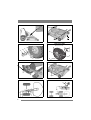
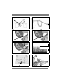
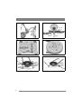
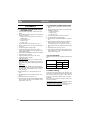
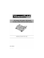
85 Combi, 95 Combi, 105 Combi
for Mountfield 2000 and 4000 series
8211-7060-80
1 125 Combi Pro
2
C
B
3
4000 series 4WD, 2000 series
A
B
C
4
A
4000 series 2WD
(D)
E
F
G
6
5
H
I
7
2
4000 series 4WD
8
4000 series 2WD
9
2000 series
10
11
17”
12
13
16”
14
1/3
15
16
3
18
17
Q
P
Q
P
45 Nm
20
19
90°
21
22
4000 series 4WD
K
2000 series
K
K
K
4
EN
ENGLISH
1 GENERAL
This symbol indicates WARNING. Serious personal injury and/or damage to
property may result if the instructions
are not followed carefully.
You must read these instructions for use
and the machine’s safety instructions
carefully.
1.1 Symbols
The following symbols appear on the machine.
They are there to remind you of the care and attention required in use.
This is what the symbols mean:
Warning!
Read the instruction manual and the safety
manual before using the machine.
Warning!
Do not insert your hands or feet under the
cover when the machine is in operation.
Warning!
Watch out for discarded objects. Keep onlookers away.
Warning!
Before starting repair work, remove the
spark plug cable from the spark plug.
1.2 References
1.2.1 Figures
The figures in these instructions for use are numbered 1, 2, 3, etc.
Components shown in the figures are marked A, B,
C, etc.
A reference to component E in figure 5 is written
“5:E”.
1.2.2 Headings
The headings in these instructions for use are numbered in accordance with the following example:
“2.3.2” is a subheading to “2.3” and is included under this heading.
When referring to headings, only the number of the
heading is normally specified. E.g. “See 2.3.2”.
2 DESCRIPTION
2.1 General
The cutting deck is intended for use on GGP’s
front mowers according to the table below.
Cutting deck
2000 series
4000 series
85 Combi
X
95 Combi
X
X
105 Combi
X
X
The cutting deck is supplied in one of the following versions:
• With manual adjustment of cutting height.
• With electrical adjustment of cutting height.
2.2 Controls
2.2.1 Cutting height adjustment
The cutting height can be adjusted between 25 and
90 mm.
Electrical cutting height adjustment
The setting can be adjusted infinitely variably using a switch on the machine.
Manual cutting height adjustment
The setting can be adjusted to a number of fixed
positions using the lever. See fig. 2.
2.2.2 Incline forwards
The rear section of the cutting deck can be raised
12 mm by moving the two pins down one hole
from the basic setting. See fig. 2.
2.2.3 Rear mounting
The cutting deck’s rear section is secured with the
pins in fig. 2.
2.2.4 Mounting in implement lifter
The deck is mounted in the implement lifter with a
chain and snap hooks.
One snap hook is intended for the working position
and can be moved in the chain links to set the lifting force. See fig. 10.
The other snap hook is intended for the washing
position.
5
EN
ENGLISH
3 ASSEMBLY
3.1 Assembly on 4WD 4000-series
and 2000-series
1. Place the deck in position in front of the machine.
2. Check that the deck mounts are installed on the
machine as follows.
• Washer (3:D). Only machines up to and including 2006.
• Deck mount (3:C).
• Washer (3:B).
• Circlip (3:A).
3. Screw the arms into each other. See fig. 5.
4. Remove the belt cover (6:H) by loosening the
screws 6:I.
5. Set the maximum cutting height.
6. Loosen the belt guide screws (21, 22:K) a
couple of turns and work off the belt from the
cutting deck’s pulley.
7. Locate the belt around the machine’s belt pulley
and cutting deck’s pulley.
8. Tighten the belt guide screws (21, 22:K).
9. Tension the belt as follows.
4WD 4000-series:
Grip the belt tensioner’s lever with your left
hand. Pull the lever and apply the tensioner to
the outside of the belt with your right hand. See
fig.7.
2000-series:
Tension the belt with the belt idler. The belt
idler should be on the inside of the belt and pull
out to the left (viewed from the driver’s position). See fig. 9.
10.Install the belt cover (6:H) with the screws
(6:I).
11.Suspend the unit in the implement lifter. See
fig. 10.
12.Perform the basic setting. See 3.4.
13.If the deck has electrical cutting height adjustment, connect the cable to the machine’s front
right socket. See fig. 13.
6
3.2 Assembly on 2WD 4000-series
1. Place the deck in position in front of the machine.
2. Check that the deck mounts are installed on the
machine as follows.
• Deck mount (4:G).
• Washer (4:F).
• Lock pin (4:E).
3. Screw the arms into each other. See fig. 5.
4. Set the maximum cutting height.
5. Locate the belt around the machine’s belt pulley.
6. Tension the belt with the belt idler. The belt
idler should be on the left side of the belt
viewed from the driver’s position. See fig. 8.
7. Suspend the unit in the implement lifter. See fig.
10.
8. Perform the basic setting. See 3.4.
9. If the deck has electrical cutting height adjustment, connect the cable to the machine’s front
right socket. See fig. 13.
3.3 Tyre pressure
Adjust the tyre pressures according to the table below.
Machine
Pressure (bar/psi)
Front
Rear
4000-series
0,6/9
0,4/6
2000-series
0,4/6
1,2/17
3.4 Basic setting
In order for the cutting deck to cut optimally, the
correct basic setting is required. The deck is in the
basic setting when its rear edge is 5 mm above its
front edge. This means that the deck is inclined
forwards.
Move the deck to the basic setting by lifting and
securing as follows.
On machines with 17” wheels: Install the washers
and the pins in the top hole. See fig. 11.
On machines with 16” wheels: Install the washers
and the pins in the middle hole. See fig. 12.
EN
ENGLISH
4 USING THE MACHINE
Check that the grass that is to be cut is
completely free of foreign objects such
as stones etc.
4.1 Cutting height
The best cutting results are achieved when the
when the top third of the grass is cut off. I.e. 2/3 of
the length of the grass remains. See fig. 14.
If the grass is long and has to be cut significantly,
cut twice using different cutting heights.
Do not use the lowest cutting heights if the lawn
surface is uneven. This would entail a risk of the
blades being damaged against the surface and the
lawn’s top layer of soil being removed.
4.2 Incline
The cutting deck’s rear section can be lifted so that
the deck has a greater forward incline than that
provided by the basic setting. This incline affects
the cutting results as follows.
4.2.1 Basic setting
When the deck is in the basic setting, the best
mulching effect and good dispersion of the cut
grass are achieved. The basic setting is recommended for normal grass. See 3.1.10.
4.2.2 Greater inclination
When the cutting deck is inclined forwards, the
“Multiclip” effect is reduced while the cut grass is
dispersed better.
Inclining forwards is recommended for thicker
grass.
4.3 Mowing advice
In order to achieve optimum mowing results, follow the advice below:
• Cut frequently.
• Run the engine at full throttle.
• The grass should be dry.
• Use sharp blades.
• Keep the underside of the cutting deck clean.
4.4 Composting/rear ejection
The deck can cut grass in two ways:
• Compost the grass into the lawn.
• Eject the grass behind the deck.
The deck is set for composting on delivery. In order to eject the grass behind the deck, the plug in
fig. 15 must be removed.
Set the deck in cleaning or service position (see
5.2/5.3) in order to remove/install the plug.
5 MAINTENANCE
5.1 Preparation
All service and all maintenance must be carried out
on a stationary machine with the engine switched
off.
Prevent the machine from rolling by always applying the parking brake.
Stop the engine.
Prevent unintentional starting of the
engine by disconnecting the spark plug
cable from the spark plug and removing the ignition key.
5.2 Washing position
1.
2.
3.
4.
Activate the parking brake.
Set the implement lifter in transport position.
Set the highest cutting height.
Detach the rear section of the deck on the right
and left-hand side as follows:
A. Lift up the left-hand rear section of the
deck slightly to reduce the load from the
cotter pin.
B. Remove pins and washer. See fig. 2.
C. Remove the right-hand cotter pin and
washer in the same way.
5. Grip the front edge of the deck and lift up. Hook
on the chain so that the deck is pointing diagonally upwards. See fig. 16.
It is absolutely forbidden to start the
engine when the deck is in the washing
position.
Reset the deck according to 3.1.
5.3 Service position, 4WD 4000-series and 2000-series
1. Activate the parking brake.
2. If the deck has electrical cutting height adjustment, disconnect the cable from the machine.
See fig. 13.
3. Set the maximum cutting height.
4. See fig. 2. Detach the rear section of the deck on
the right and left-hand side as follows:
A. Lift up the left-hand rear section of the
deck slightly to reduce the load from the
cotter pin.
B. Remove pins and washer.
C. Remove the right-hand cotter pin and
washer in the same way.
5. Remove the belt cover (6:H) by loosening the
screws 6:I.
6. Unhook the belt as follows.
7
EN
ENGLISH
4WD 4000-series:
Grip the belt tensioner’s lever with your left
hand. Pull the lever and unhook with your right
hand. See fig. 7.
2000-series:
Unhook the belt idler from the belt. See fig. 9.
7. Loosen the belt guide screws (21, 22:K) a
couple of turns and work off the belt from the
cutting deck’s pulley.
8. Force the belt off the deck’s pulley.
9. Grip the front edge of the deck and lift up. Lift
until the deck is completely vertical and rest the
rear edge on the ground. See fig. 17.
Reset the deck according to 3.1.
5.4 Service position,
2WD 4000-series
1. Activate the parking brake.
2. If the deck has electrical cutting height adjustment, disconnect the cable from the machine.
See fig. 13.
3. Set the maximum cutting height.
4. See fig. 2. Detach the rear section of the deck on
the right and left-hand side as follows:
A. Lift up the left-hand rear section of the
deck slightly to reduce the load from the
cotter pin.
B. Remove pins and washer.
C. Remove the right-hand cotter pin and
washer in the same way.
5. Release the belt tension by unhooking the belt
idler from the belt. See fig. 9.
6. Force the belt off the machine’s pulley.
7. Grip the front edge of the deck and lift up. Lift
until the deck is completely vertical and rest the
rear edge on the ground. See fig. 17.
Reset the deck according to 3.2.
5.5 Cleaning
The underside of the deck must be cleaned after
each use.
Set the deck in washing position.
Clean the underside of the deck carefully. Use water and a brush.
When the surfaces are completely dry and clean,
touch up the paintwork. Use durable yellow paint
intended for metal outdoors.
8
5.6 Blades
5.6.1 Safety
To reduce the risk of accidental injury in the event
of a collision and to protect important parts in the
cutting deck, a force limiter is integrated as follows.
• Shear bolts between blades and blade bar.
• Torque limiting between gear wheels and blade
shaft.
• Possibility of positive drive belt slipping on the
plastic gear wheels.
5.6.2 Replacing blades
Wear protective gloves when changing
blade(s) to avoid cutting yourself.
Check that the blades are always sharp. This produces the best cutting results. The blades should be
replaced once a year.
Always check the blades after a collision. If the
blade system has been damaged, defective parts
should be replaced.
Always use genuine spare parts. Nongenuine spare parts can entail a risk of
injury, even if they fit the machine.
The blades are replaceable. When replacing, both blades on the same blade bar must be replaced to avoid imbalance.
Attention!
Note the following when reassembling:
• The blades and blade bar must be installed as in
fig 18.
• The blades can be turned 1/3 of a turn in their
mountings. Select positions so that the blades
are offset 90° from each other. See “5.6.3” below.
Tightening torque:
Screws (18:P) - 24 Nm
Shear bolts (18:Q) - 9.8 Nm
In the event of a collision, the shear bolts (18:Q)
can break and the blades bend back. If this has happened, install genuine shear bolts and tighten as
above.
5.6.3 Synchronising, blades
The deck has synchronised blades.
If one of the blades has struck a solid object (e.g. a
stone), the synchronisation may be altered. This
entails a risk of the blades colliding with each other.
Correctly synchronised blades must be offset 90°
from each other. See fig. 19.
Always check synchronisation after a collision.
ENGLISH
EN
If the blades are not synchronised, one or more of
the following faults may have occurred in the cutting deck:
• The positive drive belt has slipped on the gear
wheels.
• Torque limiting between gear wheels and blade
shaft has deployed. The arrows in fig. 20 must
be opposite each other for an intact deck. When
torque limiting has deployed, the arrows are not
opposite each other.
• The blade member is incorrectly installed on
the blade shaft. Can be installed in three different positions. See 18:R.
In the event of incorrect synchronisation according
to the two first alternatives, contact an authorised
GGP workshop for repair.
6 SPARE PARTS
GGP genuine spare parts and accessories are designed specifically for GGP machines. Please note
that ‘non-genuine’ spare parts and accessories
have not been checked or approved by GGP:
The use of such parts and accessories
can affect the function and safety of the
machine. GGP accepts no responsibility
for damage or injuries caused by such
products.
7 DESIGN REGISTRATION
This product or parts thereof is covered by the following design registration:
Sweden: 66 166
Germany: 499 11 740.9
France: 577 251-253, 577 439-443
USA: 435 564
GGP reserves the right to make alterations to the
product without prior notification.
9
Manufactured by GGP Sweden AB