1
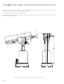
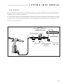
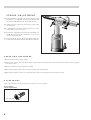
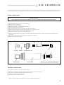
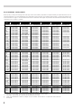
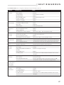
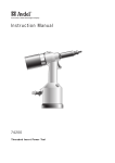
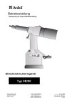
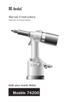
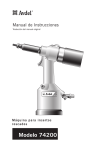
Instruction Manual
07
55
5
Pass onto user to read and keep for reference
Threaded Insert Power Tool
07555 model
AVDEL policy is one of continuous development. Specifications shown in this document may be subject to changes which
may be introduced after publication. For the latest information always consult Avdel.
SPECIFICATIONS
FOR
THE
AIR PRESSURE ■
Minimum - Maximum
FREE AIR VOLUME REQUIRED ■
@ 5.4 bar or 80 lbf/in 2
STROKE ■
MOTOR SPEED ■
PULL FORCE ■
07555
4 - 7 bar
Maximum
■
■
■
SPIN ON
■
1300 RPM
SPIN OFF
■
■
@ 5.4 bar or 80 lbf/in
2
TOOL
60 - 100 lbf/in 2
2400 RPM
■
■
■
■
■
10.6 kN
■
2380 lbf
12 litres
6.1 mm
CYCLE TIME ■
Approximately
■
2.5 seconds
■
NOISE LEVEL ■
Less than
■
70 dB(A)
■
WEIGHT ■
Without nose equipment
■
2.4 kg
VIBRATION ■
Less than
■
2.5 m/s
■
■
2
.4 ft 3
.24 in
5.3 lb
8 ft/s 2
CONTENTS
SAFETY
General
2
Specific to Type of Tool
3
General
4
Tool Dimensions
4
Air Supply
5
Stroke Adjustment
6
Operating Procedure
6
Accessories
6
Fitting
7
Servicing
7
Components
8
Regular Servicing
9
INTENT OF USE
PUTTING INTO SERVICE
NOSE ASSEMBLIES
SERVICING
Service Kit
Maintenance
General Assembly & Parts List
10
11-13
14 -15
PRIMING
FAULT
Priming Oil Details
16
Priming Procedure
16
Fault Diagnosis Table
17
DIAGNOSIS
1
SAFETY
This instruction manual must be read with particular attention to the following safety rules,
by any person installing, operating, or servicing this tool.
DO NOT USE OUTSIDE THE DESIGN INTENT.
DO NOT USE EQUIPMENT WITH THIS TOOL/MACHINE OTHER THAN THAT
RECOMMENDED AND SUPPLIED BY AVDEL.
ANY MODIFICATION UNDERTAKEN BY THE CUSTOMER TO THE TOOL/MACHINE,
NOSE ASSEMBLIES, ACCESSORIES OR ANY EQUIPMENT SUPPLIED BY AVDEL OR THEIR
REPRESENTATIVES, SHALL BE THE CUSTOMER'S ENTIRE RESPONSIBILITY. AVDEL WILL BE
PLEASED TO ADVISE UPON ANY PROPOSED MODIFICATION.
THE TOOL/MACHINE MUST BE MAINTAINED IN A SAFE WORKING CONDITION AT
ALL TIMES AND EXAMINED AT REGULAR INTERVALS FOR DAMAGE AND FUNCTION BY
TRAINED COMPETENT PERSONNEL. ANY DISMANTLING PROCEDURE SHALL BE
UNDERTAKEN ONLY BY PERSONNEL TRAINED IN AVDEL PROCEDURES. DO NOT DISMANTLE
THIS TOOL/MACHINE WITHOUT PRIOR REFERENCE TO THE MAINTENANCE INSTRUCTIONS.
CONTACT AVDEL WITH YOUR TRAINING REQUIREMENTS.
THE TOOL/MACHINE SHALL AT ALL TIMES BE OPERATED IN ACCORDANCE WITH
RELEVANT HEALTH AND SAFETY LEGISLATION. IN THE U.K. THE “HEALTH AND SAFETY AT
WORK ETC. ACT 1974” APPLIES. ANY QUESTION REGARDING THE CORRECT OPERATION
OF THE TOOL/MACHINE AND OPERATOR SAFETY SHOULD BE DIRECTED TO AVDEL.
THE PRECAUTIONS TO BE OBSERVED WHEN USING THIS TOOL/MACHINE MUST BE
EXPLAINED BY THE CUSTOMER TO ALL OPERATORS.
ALWAYS DISCONNECT THE AIRLINE FROM THE TOOL/MACHINE INLET BEFORE
ATTEMPTING TO ADJUST, FIT OR REMOVE A NOSE ASSEMBLY.
DO NOT OPERATE A TOOL/MACHINE THAT IS DIRECTED TOWARDS ANY PERSON(S).
ALWAYS ADOPT A FIRM FOOTING OR A STABLE POSITION BEFORE OPERATING THE
TOOL/MACHINE.
ENSURE THAT VENT HOLES DO NOT BECOME BLOCKED OR COVERED AND THAT
HOSES ARE ALWAYS IN GOOD CONDITION.
2
In addition to the general safety rules opposite, the following specific safety points must also
be observed:
2
THE OPERATING PRESSURE SHALL NOT EXCEED 7 BAR - 100 LBF/IN .
DO NOT OPERATE THE TOOL WITHOUT FULL NOSE EQUIPMENT, OIL PLUG AND OIL
BLEED SCREW IN PLACE.
WHEN USING THE TOOL, THE WEARING OF SAFETY GLASSES IS REQUIRED BOTH BY
THE OPERATOR AND OTHERS IN THE VICINITY TO PROTECT AGAINST FASTENER
PROJECTION, SHOULD A FASTENER BE PLACED ‘IN AIR’. WE RECOMMEND WEARING
GLOVES IF THERE ARE SHARP EDGES OR CORNERS ON THE APPLICATION.
TAKE CARE TO AVOID ENTANGLEMENT OF LOOSE CLOTHES, TIES, LONG HAIR,
CLEANING RAGS ETC., IN THE MOVING PARTS OF THE TOOL WHICH SHOULD BE KEPT
DRY AND CLEAN FOR BEST POSSIBLE GRIP.
WHEN CARRYING THE TOOL FROM PLACE TO PLACE KEEP HANDS AWAY FROM THE
TRIGGER/LEVER TO AVOID INADVERTENT START UP.
EXCESSIVE CONTACT WITH HYDRAULIC OIL SHOULD BE AVOIDED. TO MINIMIZE THE
POSSIBILITY OF RASHES, CARE SHOULD BE TAKEN TO WASH THOROUGHLY.
3
INTENT
OF USE
The hydro-pneumatic 07555 tool is designed to place Avdel threaded inserts at high speed making it ideal for batch or flow-line
assembly in a wide variety of applications throughout all industries.
Use the selection chart page 8 to select a complete tool.
It is also possible to order the base tool only (part number 07555-00200) which will not be fitted with a nose assembly. For details of
nose assemblies see pages 7 and 8.
135
5.30
74
2.91
20
.79
74
2.91
23
.90
28
1.10
25
1.00
305
12.00
129
5.10
Dimensions shown in bold are millimetres. Other dimensions are in inches.
4
102
4.00
PUTTING
AIR
INTO SERVICE
SUPPLY
All tools are operated with compressed air at an optimum pressure of 5.5 bar. We recommend the use of pressure regulators and
automatic oiling/filtering systems on the main air supply. These should be fitted within 3 metres of the tool (see diagram below) to ensure
maximum tool life and minimum tool maintenance.
Air supply hoses should have a minimum working effective pressure rating of 150% of the maximum pressure produced in the system
or 10 bar, whichever is the highest. Air hoses should be oil resistant, have an abrasion resistant exterior and should be armoured where
operating conditions may result in hoses being damaged. All air hoses MUST have a minimum bore diameter of 6.4 millimetres or 1/4 inch.
Read servicing daily details page 9.
STOP COCK
(USED DURING MAINTENANCE
OF FILTER/REGULATOR
OR LUBRICATION UNITS)
RES MAXIMUM
3 MET
0 2 4
TAKE OFF POINT
FROM MAIN SUPPLY
PRESSURE REGULATOR
AND FILTER
(DRAIN DAILY)
MAIN SUPPLY
DRAIN POINT
07
55
5
LUBRICATOR
1416
12
6 8 10
5
STROKE
ADJUSTMENT
This adjustment is necessary to ensure optimum insert
deformation. It is suggested, therefore, that a test plate with
the same thickness and hole size as workpiece be used.
■
If deformation is insufficient, the insert will rotate inside
the application.
■
If deformation is excessive, thread distortion will occur
and possibly drive screw fracture.
■
The stroke is adjusted by the amount the adjustable lock
nut 46 (parts list page 15) is screwed in or out using a
spanner and the two pins.
■
To shorten stroke, turn clockwise; to lengthen stroke, turn
anticlockwise. Adjust until optimum deformation is obtained.
OPERATING
07
55
5
■
PROCEDURE
■
First connect the tool to the air supply.
■
Offer up the insert lip first to the drive screw. A light pressure will start the motor and automatically thread the insert up against
the nose and stop.
■
Insert the fastener into the application squarely.
■
Depress the trigger halfway. This will place the insert into the application
■
Depress the trigger all the way to unscrew the drive screw from the placed insert and remove the tool.
ACCESSORIES
There is one accessory available to make the connection to your air supply.
Hose connector Part Nº 07005-00276
TO FIT 6.4mm (1/4”) BORE PIPE
1/4” BSP
6
NOSE
ASSEMBLIES
It is essential that the correct nose assembly is fitted prior to operating the tool. By knowing your original complete tool part number
or the details of the fastener to be placed, you will be able to order a new complete nose assembly using the selection tables on page 8 .
FITTING INSTRUCTIONS
IMPORTANT
The air supply must be disconnected when fitting or removing nose assemblies unless specifically instructed otherwise.
■
■
■
■
■
■
■
■
■
If still fitted remove the nose casing and the adaptor nut.
Insert drive shaft 4 into spindle.
Fit drive screw 3 onto drive shaft 4.
Insert reducing sleeve 5 (if required) into the adaptor nut.
Screw the adaptor nut onto the spindle.
Hold the spindle with a spanner* and tighten the adaptor nut clockwise.
While holding the adaptor nut with the spanner*, tighten the lock nut anticlockwise.
Screw on the nose casing and nose tip 1 with the nose tip lock nut 2.
The reverse operation is carried out for equipment removal.
■
With tool still disconnected from air supply, screw one insert onto drive screw manually - making sure the insert is flush with the end of
drive screw.
Set nose tip in exact position and lock nose tip nut clockwise with a spanner*.
Remove the insert from drive screw.
■
■
4
3
5
LOCK NUT
SPINDLE
COUNTER LOCK NUT
2
ADAPTOR NUT
NOSE CASING
●
●
1
Items in grey are included in the base tool.
Items in black make up the nose assembly.
SERVICING INSTRUCTIONS
Nose assemblies should be serviced at weekly intervals.
■
■
■
■
Remove the complete nose assembly using the reverse procedure to the ‘Fitting Instructions’.
Any worn or damaged part should be replaced by a new part.
Particularly check for wear on drive screw.
Assemble according to fitting instructions.
* refers to items included in the Avdel service kit. For complete list see page 10.
7
NOSE ASSEMBLY COMPONENTS
Nose tips vary in shape according to the insert type. Each nose assembly represents a unique assembly of components which can be
ordered individually. All nose assemblies also include item 2 nose tip locknut (part number 07555-00901). Component numbers refer
to the illustration on page 7. We recommend some stock as items will need regular replacement. Read the Nose Assemblies servicing
instructions, also on page 7 carefully.
INSERT
SIZE
COMPLETE TOOL
NOSE ASSEMBLY
1
3
4
5
LARGE FLANGE INSERTS (9698,FS58,9408,9418,9498) + STANDARD NUTSERT(9500,9538)* + NUTSERT SQ(GK08) + EUROSERT(GJ08)
07555-09103
07555-01003
07555-09003
M3
07555-09883
07555-00083
07555-00903
07555-09104
07555-01004
07555-09004
M4
07555-09884
07555-00084
07555-00904
07555-09105
07555-01005
07555-09005
M5•
07555-09885
07555-00085
07555-00905
07555-09105
07555-01005
07555-09005
M5••
07555-09185
07555-04085
07555-00915
07555-09106
07555-01006
07555-09006
M6
07555-09886
07555-00086
07555-00906
07555-09108
07555-01008
07555-09008
M8
07555-09888
07555-00088
07555-00908
–
07555-01010
07555-09010
M10
07555-09880
07555-00080
07555-00910
–
07555-01012
07555-09012
M12
07555-09882 #
07555-00082
07555-00912
07555-09154
07555-00754
07555-09054
4 UNC
07555-09854
07555-00054
07555-00854
07555-09156
07555-00756
07555-09056
6 UNC
07555-09856
07555-00056
07555-00856
07555-09158
07555-00758
07555-09058
8 UNC
07555-09858
07555-00058
07555-00858
07555-09150
07555-00750
07555-09050
10 UNC
07555-09850
07555-00050
07555-00850
1/4 UNC
07555-09148
07555-00748
07555-09048
07555-09848
07555-00048
07555-00848
5/16 UNC
07555-09140
07555-00740
07555-09040
07555-09840
07555-00040
07555-00840
3/8 UNC
–
07555-00742
07555-09042
07555-09842
07555-00042
07555-00842
07555-09150
07555-00750
07555-09070
10 UNF
07555-09870
07555-00070
07555-00850
1/4 UNF
07555-09148
07555-00748
07555-09068
07555-09868
07555-00068
07555-00848
5/16 UNF
07555-09140
07555-00740
07555-09060
07555-09860
07555-00060
07555-00840
3/8 UNF
–
07555-00742
07555-09062
07555-09862
07555-00062
07555-00842
THIN SHEET NUTSERT ( 9650, 9468, 9488, FS38 )
M3
M4
M5
M6
M8
M10
M12
4 UNC
6 UNC
8 UNC
10 UNC
1/4 UNC
5/16 UNC
10 UNF
1/4 UNF
5/16 UNF
07555-01083
07555-01084
07555-01085
07555-01086
07555-01088
07555-01080
07555-01082
07555-01054
07555-01056
07555-01058
07555-01050
07555-01048
07555-01040
07555-01070
07555-01068
07555-01060
07555-09983
07555-09984
07555-09985
07555-09986
07555-09988
07555-09980
07420-09982 #
07555-09954
07555-09956
07555-09958
07555-09950
07555-09948
07555-09940
07555-09970
07555-09968
07555-09960
07555-00993
07555-00994
07555-00995
07555-00996
07555-00998
07555-00999
07555-00992
07555-00954
07555-00956
07555-00958
07555-00950
07555-00948
07555-00940
07555-00950
07555-00948
07555-00940
07555-01003
07555-01004
07555-01005
07555-01006
07555-01008
07555-01010
07555-01012
07555-00754
07555-00756
07555-00758
07555-00750
07555-00748
07555-00740
07555-00750
07555-00748
07555-00740
07555-09103
07555-09104
07555-09105
07555-09106
07555-09108
–
–
07555-09154
07555-09156
07555-09158
07555-09150
07555-09148
07555-09140
07555-09150
07555-09148
07555-09140
07555-09003
07555-09004
07555-09005
07555-09006
07555-09058
07555-09050
07555-09048
07555-09078
07555-09070
07555-09068
07555-01003
07555-01004
07555-01005
07555-01006
07555-00758
07555-00750
07555-00748
07555-00758
07555-00750
07555-00748
07555-09103
07555-09104
07555-09105
07555-09106
07555-09158
07555-09150
07555-09148
07555-09158
07555-09150
07555-09148
07555-09003
07555-09004
07555-09005
07555-09006
07555-09008
07555-01003
07555-01004
07555-01005
07555-01006
07555-01008
07555-09103
07555-09104
07555-09105
07555-09106
07555-09108
07555-09003
07555-09004
07555-09005
07555-09006
07555-09008
07555-09010
07555-09012
07555-09054
07555-09056
07555-09058
07555-09050
07555-09048
07555-09040
07555-09070
07555-09068
07555-09060
SUPERSERT - OPEN AND CLOSED END ( FB )
M3
M4
M5
M6
8 UNC
10 UNC
1/4 UNC
8 UNF
10 UNF
1/4 UNF
07555-02083
07555-02084
07555-02085
07555-02086
07555-02058
07555-02050
07555-02048
07555-02078
07555-02070
07555-02068
07555-09583
07555-09584
07555-09585
07555-09586
07555-09558
07555-09550
07555-09548
07555-09578
07555-09570
07555-09568
07555-07103
07555-07104
07555-07105
07555-07106
07555-07158
07555-07150
07555-07148
07555-07158
07555-07150
07555-07148
M3
M4
M5
M6
M8
07555-06083
07555-06084
07555-06085
07555-06086
07555-06088
07555-09283
07555-09284
07555-09285
07555-09286
07555-09288
07555-08103
07555-08104
07555-08105
07555-08106
07555-00998
HEXSERT ( 9688 )
•
••
#
*
8
Places all inserts listed in this section except M5 large flange Thin Sheet Nutsert.
Places M5 large flange Thin Sheet Nutserts 09698-00516 ONLY.
These nose assembliles include an adaptor nut part number 74200-12119 to replace the one on the tool.
Except M8.
SERVICING
THE TOOL
Regular servicing should be carried out and a comprehensive inspection performed annually or every 500000 cycles, whichever is
sooner.
IMPORTANT
The employer is responsible for ensuring that tool maintenance instructions are given to the appropriate personnel.
The operator should not be involved in maintenance or repair of the tool unless properly trained.
DAILY
■
Daily, before use or when first putting the tool into service, pour a few drops of clean, light lubricating oil into the air inlet of the tool if no
lubricator is fitted on air supply. If the tool is in continuous use, the air hose should be disconnected from the main air supply and the tool
lubricated every two to three hours.
■
Check for air leaks. If damaged, hoses and couplings should be replaced by new items.
■
If there is no filter on the pressure regulator, bleed the air line to clear it of accumulated dirt or water before connecting air hose to tool.
■
Check that the nose assembly is correct.
■
Check the stroke of the tool is adequate to place selected insert (see stroke adjustment page 6).
■
Inspect the drive screw in the nose assembly for wear or damage. If any, renew.
WEEKLY
■
Check for oil leaks and air leaks on air supply hose and fittings.
9
Grease used during tool maintenance can be ordered as a single item, the part number is shown in the service kit below.
MOLY
LITHIUM
GREASE
FIRST AID
SKIN: As the grease is completely water resistant it is best
removed with an approved emulsifying skin cleaner.
INGESTION: Make the individual drink 30ml Milk of
Magnesia, preferably in a cup of milk.
EP
3753
S A F E T Y
D A T A
FIRE
FLASH POINT: Above 220°C.
Not classified as flammable.
Suitable extinguishing media: CO 2, Halon or water spray
if applied by an experienced operator.
EYES: Irritant but not harmful. Irrigate with water and
seek medical attention.
HANDLING
Use barrier cream or oil resistant gloves
ENVIRONMENT
Scrape up for burning or disposal on approved site.
STORAGE
Away from heat and oxidising agent.
For all servicing we recommend the use of the service kit (part number 07900-05550).
SERVICE KIT
SERVICE KIT
ITEM PART Nº
07900-00163
07900-00225
07900-00162
07900-00408
07900-00004
07900-00519
07900-00426
07900-00411
10
DESCRIPTION
ALLEN KEY
ALLEN KEY
ALLEN KEY
ALLEN KEY
CIRCLIP PLIERS
IMPACT SOCKET
SPANNER
PRIMING TOOL
Nº OFF
ITEM PART Nº
1
1
1
1
1
1
2
1
07900-00010
07900-00151
07900-00351
07900-00371
07900-00393
07900-00516
07900-00518
07992-00020
(Continued)
DESCRIPTION
PIN PUNCH
'T' HANDLE EXTENSION
3mm A/F ALLEN KEY
LOCTITE 222
14 x 15mm SPANNER
PISTON EXTRACTOR
PRIMING TOOL EXTENSION
GREASE
Nº OFF
1
1
1
1
1
1
1
1
MAINTENANCE
Every 500000 cycles the tool should be completely dismantled and components replaced where worn, damaged or when recommended.
All ‘O’ rings and seals should be replaced with new ones and lubricated with Moly Lithium grease EP 3753 before assembling.
IMPORTANT
Safety Instructions appear on pages 2 & 3.
The employer is responsible for ensuring that tool maintenance instructions are given to the appropriate personnel.
The operator should not be involved in maintenance or repair of the tool unless properly trained.
The airline must be disconnected before any servicing or dismantling is attempted unless specifically instructed otherwise.
It is recommended that any dismantling operation be carried out in clean conditions.
Item numbers in bold refer to the general assembly and parts list page 14 and 15.
Before proceeding with dismantling, empty the oil from the tool. Remove oil plug 49 from the handle assembly and drain the oil into
a suitable container.
Prior to dismantling the tool it is necessary to remove the nose assembly. For simple removal instructions see the nose assemblies section, page 7.
For total tool servicing we advise that you proceed with dismantling of sub-assemblies in the order shown on pages 11 to 13.
PNEUMATIC SCREW DRIVE UNIT
■
■
■
■
Remove screws 47 using an Allen Key* and spanner*, and remove cover 2.
Carefully remove two nylon tubes 53 from the head and handle assembly 26, NOT FROM THE MOTOR.
Using combination spanner*, tighten lock nut 46 into head and handle assembly 26.
Using two combination spanners*, unscrew and remove pneumatic motor 1. Remove adaptor nut 3. Take care not to lose the push rod 64.
■
Clean and inspect components and renew any worn or damaged items.
■
■
Assemble in reverse order of dismantling.
Lock screws 47 using ‘Loctite’ 222.
* refers to items included in the Avdel service kit. For complete list see page 10.
11
HYDRAULIC HEAD ASSEMBLY
■
Grip the tool in a vice fitted with soft jaws.
Remove rubber base plug 30.
Using circlip pliers*, remove retaining ring 29.
Screw in extractor* to base cover 32 and remove base cover.
Using reverse end of extractor*, screw onto piston rod 25.
Remove piston rod 25 with air piston 31 and seal 27.
Remove spring 39.
Drain away oil.
Using two spanners*, loosen lock nut 10 enabling spindle 13 to be unscrewed and removed from movement pivot 5.
Using an Allen key* to hold movement pivot 5 steady, unscrew lock nut 11 completely and remove.
From rear of tool, remove movement pivot 5 and shim adjustment ring 8.
Knock out pin 4 from movement pivot 5 and remove movement pivot 5 from adaptor nut 3.
Using combination spanner*, remove lock nut 46.
Remove spring 45.
Remove piston 6 together with seal 24.
Using Allen key*, unscrew lock nut 10 and remove seal 9.
Unscrew rod guide 23 using impact socket* and ‘T’ bar extension* and remove the rod guide complete with locknut 40, ‘O’ Ring 41 and
seal 24.
Place rod guide 23 in a vice (holding on the spanner flats) and unscrew lock nut 40 using Allen key*, enabling seal 24 to be removed.
■
■
■
■
■
Assemble in reverse order of dismantling, observing the following:
Use new pin 4 when assembling movement pivot 5.
Ensure locknut 11 is not locked against piston 6. The locknut’s only function is to hold spindle 13 in place.
Lock nut 40 is screwed on until top face of the locknut is level with the top face of rod guide 23.
Smear the last two threads (next to spanner flats) of rod guide 23 with ‘Loctite’ 222.
■
■
■
■
■
■
■
■
■
■
■
■
■
■
■
■
■
INTENSIFIER PISTON GUIDE ASSEMBLY
■
■
■
■
■
Unscrew rod guide 23 using impact socket* and ‘T’ bar extension* and remove the rod guide complete with locknut 40,
‘O’ Ring 41 and seal 24.
Place rod guide 23 in a vice (holding across the spanner flats) and unscrew lock nut 40 using Allen Key*, enabling seals 24 to be
removed.
Assemble components in reverse order of dismantling, observing the following:
Lock nut 40 is screwed home until top face of the locknut is level with the top face of rod guide 23.
Smear the last two threads (next to spanner flats) of rod guide 23, with ‘Loctite 222’.
* refers to items included in the Avdel service kit. For complete list see page 10.
12
PNEUMATIC TRIGGER VALVE ASSEMBLY
■
■
■
■
■
Using Allen key*, loosen screw 16.
Lay the tool on its side and with pin punch*, gently tap trigger pin 17 free of its housing to release trigger 18.
Using spanner*, release lock nut 20.
Connect airline to the tool, and taking the necessary precautions, blow out the valve plunger 42 from the head and handle assembly 26.
Remove locking washer 44 by releasing adjacent screw 16.
Remove valve pivot 19.
■
Assemble in reverse order of dismantling.
PNEUMATIC MOTOR ASSEMBLY
■
■
■
■
■
■
■
■
■
■
■
Using Allen key*, loosen screw 47 to enable the nylon tubes to be removed.
Place motor assembly in a vice fitted with soft jaws.
Remove sleeve 63 using combination spanner*.
Remove push rod 64 carefully.
Pull out bearing 60.
Pull out spider 68 containing three locating pins.
Remove three planet gears 61.
Pull out planet gear 69 with spacer 70.
Tap the face of the motor casing 76 on a wood or plastic surface and allow the stator 73 to drop.
Grip the flat end of the rear end plate 74 gently in a vice, allowing the small shoulder on the stator 73 to rest on the vice jaw top surface.
Using a soft hammer, tap down and free the rotor 72 and the rotor blades 59.
■
Assemble in reverse order of dismantling, taking care to replace pin 75 in the centre hole of three holes located within the rear end plate
and the centre hole within the three internal holes of the body casting.
IMPORTANT
Check the tool against daily and weekly servicing.
Priming is ALWAYS necessary after the tool has been dismantled and prior to operating.
* refers to items included in the Avdel service kit. For complete list see page 10.
13
GENERAL ASSEMBLY OF BASE TOOL 07555-00200
)
"
(.OO5
.10mm
002")/ . STROKE
(.
m
m
AX
.05
ON M
4
3
6
5
7
8
9
11
10
12
13
14
2
1
16
17
47
48
18
45
46
54
16
44
16
19
43
20
42
21
22
41
23
47
53
52
16
51
16
49
50
40
24
39
25
38
26
SCRAP VIEW OF TUBE
& FAIRING ATTACHMENT
27
37
36
28
35
56
57
58
59
60
60
55
33
34
61
62
63
64
65
78
77
76
75
74
73
72
71
70
69
PNEUMATIC MOTOR ASSEMBLY
14
68
67
66
32
31
30
29
15
07555-00200 PARTS LIST
ITEM
PART Nº
1
2
3
4
5
6
7
8
9
10
11
12
13
14
15
16
17
18
19
20
21
22
23
24
25
26
27
28
29
30
31
32
33
34
35
36
37
38
39
40
41
07555-00601
07555-00110
07555-00703
07555-00715
07555-00704
07555-00706
07555-00707
07555-00705
07265-02004
07555-00802
07555-00803
07555-00808
07555-00804
07555-00806
07555-00805
07555-00403
07555-00402
07555-00401
07555-00307
07555-00306
07555-00305
07555-00308
07555-00203
07555-00202
07555-00204
07555-00101
07555-00108
07555-00107
07555-00106
07555-00115
07555-00104
07555-00105
07005-00015
07005-00041
07555-00102
07555-00114
07003-00029
07555-00109
07555-00205
07555-00201
07555-00206
DESCRIPTION
PNEUMATIC MOTOR ASSEMBLY
COVER
ADAPTOR NUT
PIN
MOVEMENT PIVOT
PISTON
SEAL
SHIM ADJUSTMENT RING
SEAL
LOCK NUT
LOCK NUT
COUNTER LOCK NUT
SPINDLE
NOSE CASING
ADAPTOR NUT
SCREW
TRIGGER PIN
TRIGGER
VALVE PIVOT
LOCK NUT
'O' RING
PLASTIC RING
ROD GUIDE
SEAL
PISTON ROD
HEAD & HANDLE ASSEMBLY
SEAL
'O' RING
RETAINING RING
RUBBER BASE PLUG
AIR PISTON
BASE COVER
SEALING WASHER
DOUBLE MALE CONNECTOR
CONNECTOR
WASHER
'O' RING
PLASTIC COVER
SPRING
LOCK NUT
'O' RING
QTY SPARES ITEM
1
1
1
1
1
1
1
1
1
1
1
1
1
1
1
5
1
1
1
1
3
3
1
1
1
1
1
1
1
1
1
1
1
1
1
1
2
1
1
1
1
1
1
5
3
3
1
1
2
-
42
43
44
45
46
47
48
49
50
51
52
53
54
55
56
57
58
59
60
61
62
63
64
65
66
67
68
69
70
71
72
73
74
75
76
77
78
79
80
81
PART Nº
07555-00304
07555-00301
07555-00302
07555-00702
07555-00701
07555-00111
07555-00116
07555-00501
07555-00506
07555-00502
07555-00503
07555-00504
07555-00113
07555-09221
07555-09219
07555-09217
07555-09215
07555-09213
07555-09206
07555-09208
07555-09205
07555-09202
07555-09203
07555-09223
07555-09222
07555-09224
07555-09204
07555-09207
07555-09209
07555-09210
07555-09212
07555-09211
07555-09214
07555-09216
07555-09201
07555-09218
07555-09220
07900-00426
07900-00354
07900-00636
DESCRIPTION
VALVE PLUNGER
'O' RING
LOCKING WASHER
SPRING
LOCK NUT
SCREW
AIR MOTOR RUBBER CASING
OIL PLUG
OIL SEAL WASHER
'O' RING
ADAPTOR STOP RING
NYLON TUBE
SILENCER
KNOB
SPRING
'O' RING
BEARING
ROTOR BLADE
BEARING
PLANET GEARS
LOCKNUT
SLEEVE
PUSH ROD
BUSH
SCREW
'O' RING
SPIDER
PLANET GEAR
SPACER
PLATE
ROTOR
STATOR
REAR END PLATE
PIN
MOTOR CASING
BALL
'O' RING
COMBINATION SPANNER
TIE ON SAFETY LABEL
TOOL INSTRUCTION MANUAL
QTY SPARES
1
2
1
1
1
2
1
1
1
2
2
2
1
1
1
1
1
4
2
3
1
1
1
1
1
2
1
1
1
1
1
1
1
1
1
1
1
1
1
1
2
1
2
2
2
1
2
4
4
1
2
-
15
PRIMING
Priming is ALWAYS necessary after the tool has been dismantled and prior to operating. It may also be necessary to restore the full
stroke after considerable use, when the stroke may be reduced and inserts are not fully placed by one operation of the trigger.
OIL
DETAILS
The recommended oil for priming is Hyspin VG32 available in 0.5l (part number 07992-00002) or one gallon containers (part number
07992-00006). Please find specific table and safety data below.
HYSPIN
VG
32
OIL
S A F E T Y
D A T A
FIRST AID
SKIN: Wash thoroughly with soap and water as soon as
possible. Casual contact requires no immediate attention.
Short term contact requires no immediate attention.
INGESTION: Seek medical attention immediately.
DO NOT induce vomiting.
EYES: Irrigate immediately with water for several minutes.
Although NOT a primary irritant, minor irritation may occur
following contact.
FIRE
Suitable extinguishing media: CO2, dry powder, foam or
water fog. DO NOT use water jets.
ENVIRONMENT
WASTE DISPOSAL: Through authorised contractor to a
licensed site. May be incinerated.
Used product may be sent for reclamation.
SPILLAGE: Prevent entry into drains, sewers and water courses.
Soak up with absorbent material.
HANDLING
Wear eye protection, impervious gloves (e.g. of PVC) and a
plastic apron. Use in well ventilated area.
STORAGE
No special precautions.
PROPERTIES
PROPERTIES
RESULT
ISO oil type
ISO viscosity grade
Kinematic viscosity
Relative density
Viscosity Index
Pour point
Open Flash point
Neutralisation value mg KOH/g
HL
32
cS @ 40°C
@ 100°C
at 20°C
°C
°C
32
5.3
0.875
95
- 30
232
1.5
RESULT
Foaming tendency/stability
ml @ 24°C
ml @ 93.5°C
ml @ 24°C after test @ 93.5°C
Air release value minutes to
0.2% air content @ 50°C
Seal compatibility index
Water separation time
in minutes to 40-40-0 @54°C
@83°C
Trace/Nil
20/Nil
Trace/Nil
PROCEDURE
Item numbers in bold refer to the general assembly and parts list pages 12 and 13.
IMPORTANT
All operations should be carried out on a clean bench, with clean hands in a clean area.
Ensure that the oil is perfectly clean and free from air bubbles.
Care MUST be taken at all times, to ensure that no foreign matter enters the tool, or serious damage may result.
The tool must remain on its side throughout the priming sequence.
■
■
■
■
■
■
■
■
■
■
■
■
■
If already fitted remove nose tip and nose tip lock nut.
Place tool on its side, oil plug 49 side up.
With an Allen key*, unscrew oil plug 49 and remove with oil seal washer 50.
Unscrew adjustable locknut 46 to its maximum setting.
Insert priming tool extension* into front of nose casing.
Screw priming tool* into front of nose casing and screw in threaded centre spindle as far as possible.
Fill tool with priming oil rocking gently to expel air.
Replace oil seal washer 50 and oil plug 49 and tighten.
Unscrew oil plug 49 by ONE TURN only, using an Allen key*. Slowly unfasten the priming tool centre spindle then remove priming tool
extension, then tighten the adjustable locknut 46.
Wait until oil appears all around oil plug 49 then re-tighten. Wipe excess oil away.
Using an Allen Key* open oil plug 49 and remove with oil seal washer 50.
Top-up with priming oil to reset level. Replace oil seal washer 50 and oil plug 49 and fully tighten.
It is necessary to fit the appropriate nose equipment and adjust the tool stroke prior to operating the tool.
* refers to items included in the Avdel service kit. For complete list see page 10.
16
4
10
15
15
FAULT
DIAGNOSIS
Item numbers in bold refer to the general assembly and parts list pages 14 and 15.
SYMPTOM
POSSIBLE CAUSE
REMEDY
Pneumatic motor
➝ Air leak from motor
➝ Check for worn seals. Replace
runs slowly
➝ Low air pressure
➝ Increase
➝ Air way blockage
➝ Clear restriction in air supply
➝ Worn drive screw
➝ Replace
➝ Rotor blades 59 jamming
➝ Lubricate tool through air inlet
➝ Air leak on pipes 53
➝ Replace
➝ Damaged ‘O’ Rings 51
➝ Replace
Insert does not
➝ Stroke incorrectly set
➝ Adjust
deform properly
➝ Air pressure outside the tolerance
➝ Adjust
➝ Low oil level
➝ Prime tool
➝ Insert out of grip
➝ Check grip range of Insert
Drivescrew turns
➝ Worn or damaged drive shaft
➝ Replace
independent of
➝ Worn or damaged drive screw
➝ Replace
motor
➝ Adaptor nut 15 loose
➝ Tighten
➝ Nose Equipment incorrectly assembled
➝ Disconnect air supply - refit nose equipment carefully
Insert will not
➝ Incorrect Insert thread size
➝ Change to correct insert
place onto
➝ Incorrect drive screw fitted
➝ Change to correct drive screw
drivescrew
➝ Worn or damaged drive screw
➝ Replace
➝ Nose equipment incorrectly assembled
➝ Disconnect air supply, refit nose equipment carefully
➝ Excessive stroke/
➝ Disconnect tool from air supply. Insert a 3mm Ø Rod through hole in nose
Tool is jammed
on placed insert
Defective Insert/
casing to prevent casing from turning. Using a spanner loosen Nose Tip
Worn or defective drive screw
nut. Rotate tool to unscrew from insert. Replace insert and drive screw
Drive screw
➝ Stroke of tool excessive
➝ Reset stroke
breaks
➝ Side load on drive screw
➝ Hold tool square to application when placing Insert
Drive screw does
➝ Adaptor nut 15 loose
➝ Tighten
not rotate
➝ No air supply
➝ Connect
clockwise
➝ Insufficient gap between locknut 11 and
➝ Adjust to 1.5 mm gap to 2mm gap
spindle 13
➝ Push Rod 64 too short
➝ Replace
➝ Air motor jammed
➝ Lubricate tool at air inlet 34. If insufficient dismantle & clean air motor
Trigger
➝ Static friction
➝ Depress trigger 18 a few times
inoperative
➝ Low air pressure
➝ Increase air pressure
➝ Valve plunger 42 remains stuck
➝ Depress trigger 18 several times. Lubricate tool through air inlet 34.
➝ Seal 7 is defective
➝ Replace
Drive screw does
➝ Adaptor nut 15 loose
➝ Tighten
not rotate
➝ No air supply
➝ Connect
anti-clockwise
➝ ‘O’ ring 67 leaking air
➝ Replace
➝ Push rod 64 jammed
➝ Lubricate or replace
➝ Air motor jammed
➝ Lubricate tool at air inlet 34. If insufficient dismantle & clean air motor
thoroughly
If unsuccessful , dismantle, clean and lubricate trigger elements.
Drivescrew does
not return and/or
keeps rotating
anti-clockwise
thoroughly
17
Engineered Fastening and Assembly Systems
Declaration of Conformity
We,
Avdel SRL, Via Manin 350-21, 20099 Sesto Giovanni, Milan, Italy.
declare under our sole responsibility that the product
type 07555
Serial Nº
..............................................
to which this declaration relates is in conformity with the following standards or other formative documents
EN292 part 1 and part 2
ISO 8662 part 1 and part 7
ISO 3744 and PNEUROP test code PN8TC1
ISO PREN792 part 6 & 14
following the provisions of the Machine Directive 89/392/EEC
(as amended by Directive 91/368/EEC, 93/44/EEC) and 93/68/EEC
Milan - date of issue
M. Dellefave - Quality Manager
Overseas Companies:
Avdel Pty Ltd, 2263 Princes Highway, Mulgrave, Victoria 3170 Australia
Avdel GmbH, Industriestrasse B 13/Halle 2, A-2345 Brunn/Gebirge Austria
Avdel Inc, 2696 Slough Street, Mississauga, Ontario L4T 1G3 Canada
Avdel SA, 33 bis, rue des Ardennes, BP4 75921 Paris Cedex 19 France
Avdel GmbH, Postfach 1463, D-30835 Langenhagen Germany
Avdel SRL, Via Manin 350-21, 20099 Sesto Giovanni, Milan Italy
Avdel KK, Takahashi Building, 9-3, 5 Chome, Nishi-tenma, Kita-ku, Osaka 530 Japan
Avdel SA, Poligono Prado Overa, Edificio Prado Park, Autovia Madrid Toledo KM 7.8, Leganes 28916, Madrid Spain
Avdel Korea Ltd, Samyung Building, 1486-2 Socho Dong, Socho Ku, Seoul S. Korea
Ejot & Avdel System AB, PO BOX 9013 S-700 09 Örebro Sweden
Avdel Corporation, 50 Lackawanna Avenue, Parsippany, New Jersey 07054 USA
07900-00636 JAN 1995 GB
World Headquarters:
Avdel Systems Ltd, Mundells, Welwyn Garden City, Herts AL7 1EZ United Kingdom - Tel: (01707) 328161 Fax: (01707) 338828
® © ™ Products mentioned and /or illustrated within this publication are subject to patent, design or copyright protection in many countries.