1
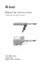
Betriebsanleitung
Übersetzung der Original-Betriebsanleitung
Blindnietmutterngerät
Typ 74200
Düko Vertriebs-GmbH
Lülsdorfer Straße 32
53842 Troisdorf
Telefon: 02241/2520150
Fax: 02241/25201511
E-Mail: [email protected]
Internet: www.dueko.com
Hr.-Nr.: 16390
Ust.-IdNr.: DE 122652573
Geschäftsführer: O. Düren
F. Düren
Der Geschäftsgrundsatz von Avdel ist die fortlaufende Weiterentwicklung. Die in diesem Dokument angegebenen
technischen Daten sind Änderungen unterworfen, die nach Veröffentlichung eingeführt werden können. Für die neuesten
Informationen stets Avdel zu Rate ziehen.
250
9 .8 4
27Ø
1 .0 6 Ø
63Ø
2 .4 8 Ø
63
2.48
280
11.02
115Ø
4.53Ø
TECHNISCHE
BETRIEBSDRUCK
LUFTVERBRAUCH
DATEN
FÜR
GERÄT
min./max.
bei 5 bar / 75 lbf/in
2
TYP
5 - 7 bar
75 - 100 lbf/in 2
8l
,28 ft 3
7 mm
,276 in
HUB
Max.
MOTORDREHZAHL
Rechtslauf
2000 U/min
Linkslauf
2000 U/min
ZUGKRAFT
bei 5 bar / 75 lbf/in
2
TAKTZEIT
ca.
ARBEITSGERÄUSCH
geringer als
GEWICHT
ohne Ausrüstung
SCHWINGUNGEN
geringer als
74200
19,1 kN
4300 lbf
2,5 s
75 dB(A)
4,85 lb
2,2 kg
2,5 m/s
2
INHALTSANGABE
SICHERHEITSVORSCHRIFTEN
Allgemeines
2
Spezifisch für Gerät 74200
3
Allgemeines
4
Druckluftversorgung
5
Hubverstellung
5
Betrieb
5
Einbau
6
Wartung
6
Einzelteile
7
Regelmäßige Wartung
8
Werkzeugsatz
9
ARBEITSBEREICH
INBETRIEBNAHME
AUSRÜSTUNGEN
WARTUNG DES GERÄTES
Wartung
Übersicht und Ersatzteilliste
9-11
12-13
ÖLWECHSEL
Einzelheiten für das Auffüllen mit Öl
14
Auffüllvorgang
14
Beseitigung von Störungen
15
BESEITIGEN VON
STÖRUNGEN
1
SICHERHEITSVORSCHRIFTEN
Beim Lesen dieser Betriebsanleitung muß der mit der Installation, dem Betrieb und der
Wartung des Gerätes beauftragte Mitarbeiter den nachstehenden Sicherheitshinweisen
besondere Aufmerksamkeit schenken.
NICHT ZWECKENTFREMDET VERWENDEN.
MIT DIESEM GERÄT KEINE ANDEREN ALS DIE VON AVDEL EMPFOHLENEN UND GELIEFERTEN
AUSRÜSTUNGEN VERWENDEN.
AN DEM GERÄT DÜRFEN KEINE VERÄNDERUNGEN DURCHGEFÜHRT WERDEN. SOLLTE
DIESES DOCH GESCHEHEN, SO TRÄGT DER KUNDE HIERFÜR DIE ALLEINIGE
VERANTWORTUNG. BEI GEWÜNSCHTEN MODIFIKATIONEN SPRECHEN SIE BITTE AVDEL
AN.
DER SICHERE BETRIEBSZUSTAND DES GERÄTES/DER MASCHINE IST JEDERZEIT ZU
GEWÄHRLEISTEN. EINE ÜBERPRÜFUNG AUF FUNKTION UND SCHÄDEN HAT REGELMÄSSIG
DURCH FACHPERSONAL ZU ERFOLGEN. DIE DEMONTAGE DARF NUR DURCH
AUTORISIERTES FACHPERSONAL UND UNTER VERWENDUNG DER BETRIEBSANLEITUNG
ERFOLGEN. AUF WUNSCH FÜHREN WIR GERÄTESCHULUNGEN DURCH, UM IHR PERSONAL
AUF DEN ERFORDERLICHEN KENNTNISSTAND ZU BRINGEN.
DAS GERÄT MUSS JEDERZEIT ENTSPRECHEND DEN SICHERHEITSBESTIMMUNGEN
BETRIEBEN WERDEN. EINZELHEITEN SIEHE MASCHINENRICHTLINIE 89/392/EG. SOLLTEN
SIE FRAGEN HIERZU HABEN, BITTE SPRECHEN UNS AN.
DER
KUNDE
IST
VERANTWORTLICH
DAFÜR,
DASS
ALLE
NOTWENDIGEN
SICHERHEITSMASSNAHMEN EINGEHALTEN WERDEN.
TRENNEN SIE BEI ALLEN WARTUNGSARBEITEN, AUCH ZUM WECHSEL VON MUNDSTÜCKEN
ODER AUSRÜSTUNGEN, DAS GERÄT VON DER DRUCKLUFT.
BETÄTIGEN SIE DAS GERÄT NICHT, WENN ES AUF PERSONEN GERICHTET IST.
ACHTEN SIE AUF EINEN FESTEN STAND DES BEDIENUNGSPERSONALS.
STELLEN SIE SICHER, DASS BE- UND ENTLÜFTUNGSLÖCHER NICHT VERSTOPFT ODER ABGEDICHTET
SIND, UND DASS SCHLAUCHLEITUNGEN SICH EINEM EINWANDFREIEN ZUSTAND BEFINDEN.
2
Zusätzlich zu den gegenüberliegend aufgeführten allgemeinen Sicherheitsmaßnahmen
sind außerdem die nachfolgenden spezifischen Punkte zu beachten:
DER ARBEITSDRUCK DARF 7 BAR - 100 LBF/IN 2 NICHT ÜBERSCHREITEN.
DAS GERÄT NICHT OHNE MONTIERTE AUSRÜSTUNGEN, INNENSECHSKANTSCHRAUBE (42)
UND ENTLÜFTUNGSSCHRAUBE (48) BETREIBEN.
DER BEDIENER UND IN DER NÄHE STEHENDE PERSONEN MÜSSEN WÄHREND DES
EINSATZES DES GERÄTES EINE SCHUTZBRILLE TRAGEN, UM VOR GEFAHREN DURCH
FEHLNIETUNGEN GESCHÜTZT ZU SEIN. BEI SCHARFKANTIGEN BAUTEILEN EMPFEHLEN
WIR DAS TRAGEN VON SCHUTZHANDSCHUHEN.
ACHTEN SIE DARAUF, DASS SICH KEINE KLEIDUNGSSTÜCKE, KRAWATTEN, PUTZLAPPEN
ODER LANGE HAARE IN DEM GERÄT VERFANGEN.
DAS GERÄT IST SAUBER UND
TROCKEN ZU HALTEN, DAMIT ES DEM BETREIBER NICHT AUS DER HAND RUTSCHT.
DAS GERÄT BEIM TRANSPORT NICHT AM HANDGRIFF UMFASSEN, UM EIN UNGEWOLLTES
AUSLÖSEN ZU VERMEIDEN.
VERMEIDEN SIE ÜBERMÄSSIGEN KONTAKT MIT HYDRAULIKÖL. FALLS HAUTREIZUNGEN
AUFTRETEN, IST EIN GRÜNDLICHES WASCHEN MIT WASSER ZU EMPFEHLEN.
3
A
RBEITSBEREICH
Das Druckluftgerät 74200 wurde konstruiert, um Avdel-Blindnietmuttern mit hoher Geschwindigkeit zu verarbeiten. Es ist deshalb ideal
für die Serienfertigung in einer Vielzahl von Industriebereichen.
Der Auswahltabelle auf Seite 7 entnehmen Sie die Bestellnummern für kpl. Geräte (Grundgerät + Ausrüstung).
Es ist auch möglich, nur das Grundgerät (Art-Nr. 74200-12000) ohne Ausrüstung zu bestellen.
Die fettgedruckten Maße sind in mm und die anderen Maße in Zoll.
4
INBETRIEBNAHME
DRUCKLUFTVERSORGUNG
Alle Werkzeuge werden mit Druckluft betrieben. Der optimale Betriebsdruck beträgt 5,5 bar. Wir empfehlen die Verwendung von Druckreglern
und automatischen Filtersystemen für den Anschluß an die Druckluftleitung. Diese sollten innerhalb von 3 m vom Gerät angebracht werden
(siehe nachstehendes Diagramm), um max. Werkzeuglebensdauer und min. Werkzeugwartung zu erreichen.
Die Druckluftversorgungsschläuche sollten für einen min. Nenndruck von 150 % des im System erzeugten Höchstdrucks oder 10 bar, je
nachdem, was der höhere Wert ist, ausgelegt werden. Druckluftschläuche sollten ölfest sein, eine abriebfeste Hülle besitzen und, wo
Betriebsbedingungen zu Schäden führen können, bewehrt sein. Alle Druckluftschläuche müssen eine min. lichte Weite von 6,4 mm oder
1/4" haben.
Für Einzelheiten der täglichen Wartung siehe Seite 8.
ABSPERRHAHN
(ZUR VERWENDUNG WÄHREND WARTUNG
VON FILTER/REGLER ODER ÖLER)
MA
X. 3 m
0 2 4
ÖLER
1416
12
6 8 10
ANSCHLUSSSTELLE
AN NETZVERSORGUNG
DRUCKREGLER UND
ABFLUSSSTELLE AN
FILTER (TÄGLICH ABLASSEN) HAUPTVERSORGUNG
HUBEINSTELLUNG
Diese Einstellung ist erforderlich, um eine optimale Verformung
der Blindnietmutter zu erreichen. Es wird deshalb empfohlen, ein
Prüfblech zu verwenden, dessen Dicke und Lochgröße dem zu
verwendenden Bauteil entspricht.
Bei ungenügender Verformung dreht sich die Blindnietmutter
innerhalb der Applikation.
Bei übermäßiger Verformung erfolgt ein Verzug des Gewindes
und ein möglicher Bruch der Ziehschraube.
Die Hubeinstellung erfolgt durch das Ein- oder Herausdrehen des
hinteren Gehäuses 86 (Ersatzteilliste, Seite 13).Um die
Hubeinstellung zu entriegeln, muß der Raststift 83 nach vorne
geschoben werden. Das Eindrehen des hinteren Gehäuses (im
Uhrzeigersinn) verkürzt den Hub und das Herausdrehen verlängert
den Hub. Das hintere Gehäuse nicht mehr als 5 Umdrehungen
herausdrehen, da das Gerät sonst nicht mehr arbeitet. Wenn der
Hub optimal eingestellt ist, den Raststift loslassen; er sichert dann
das hintere Gehäuse gegen Verdrehen.
SETZVORGANG
■
■
■
■
■
Die passende Ausrüstung montieren und das Gerät an die Druckluftleitung anschließen.
Die Blindnietmutter mit der Lippe voran auf die Ziehschraube stecken. Durch leichten Druck startet den Motor und spindelt die
Blindnietmutter automatisch auf.
Das Gerät mit der aufgeschraubten Mutter rechtwinklig in die Applikation einführen.
Auslöser ganz durchdrücken. Das Gerät führt nun den eingestellten Hub aus und setzt die Mutter. Anschließend schaltet das Gerät
automatisch in den Linkslauf und spindelt aus der Mutter aus.
Nach dem Loslassen des Auslösers wird die Drehbewegung der Ziehschraube gestoppt und das Gerät ist bereit für den nächsten Setzvorgang.
5
AUSRÜSTUNGEN
Vor Inbetriebnahme des Gerätes muß die passende Ausrüstung montiert werden. Die Bestellnummern für komplette Ausrüstungen und
für die Einzelteile der Ausrüstung entnehmen Sie bitte Seite 7.
MONTAGEANWEISUNGEN
WICHTIG
Bei allen Wartungs- und Einrichtungsarbeiten, auch zur Montage der Ausrüstung muß, soweit nicht an anderer Stelle
besonders angewiesen, das Gerät von der Druckluftleitung getrennt werden.
■
■
■
■
■
■
■
■
■
Falls noch montiert, die Mundstückhülse und die Kontermutter abschrauben.
Mitnehmerdorn 4 in die Spindel einsetzen.
Ziehschraube 3 auf Mitnehmerdorn 4 stecken.
Führungsbuchse 5 (wenn erforderlich) in die Kontermutter einsetzen.
Kontermutter auf die Spindel schrauben.
Spindel mit Maulschlüssel festhalten und Kontermutter festziehen.
Während das Mundstückhinterteil vom Schraubenschlüssel* gehalten wird, die Kontermutter nach links anziehen.
Das Mundstück 1 mit Gewindering 2 in die Mundstückhülse einschrauben und diese auf das Gerät schrauben.
Der Abbau der Ausrüstung erfolgt in umgekehrter Reihenfolge.
■
Das Gerät bleibt von der Druckluftversorgung getrennt. Eine Blindnietmutter von Hand auf die Ziehschraube drehen. Dabei
sicherstellen, daß die Mutter bündig mit dem Ende der Ziehschraube abschließt.
Das Mundstück entsprechend einstellen und den Gewindering mit Hilfe eines Maulschlüssels im Uhrzeigersinn kontern.
Die Blindnietmutter von der Ziehschraube entfernen.
■
■
4
LOCK NUT
SPINDLE
KONTERMUTTER
SPINDEL
ADAPTOR NUT
KONTERMUTTER
MUNDSTÜCKHÜLSE
3
5
FRICTION RING
KLEMMRING
2
1
NOSE CASING
●
●
Die grau gezeichneten Teile gehören zum Grundgerät.
Die schwarz gezeichneten Teile gehören zur Ausrüstung.
WARTUNGSANWEISUNGEN
Die Ausrüstungen sind wöchentlich zu warten.
■
■
■
■
Die Ausrüstungen in umgekehrter Reihenfolge der Montageanweisungen ausbauen.
Verschlissene oder beschädigte Teile sind durch neue zu ersetzen.
Insbesondere die Ziehschraube auf Verschleiß prüfen.
Entsprechend der Montageanweisungen zusammenbauen.
* Diese Teile sind Bestandteil des 74200-Werkzeugsatzes. Die komplette Werkzeugliste finden Sie auf Seite 9.
6
EINZELTEILE DER AUSRÜSTUNG
Die Form der Mundstücke ist je nach Mutterntyp unterschiedlich. Jede Ausrüstung besteht aus verschiedenen Einzelteilen, die auch separat
bezogen werden können. Alle Ausrüstungen enthalten einen Gewindering 2 (Art-Nr.: 7555-0901). Die Positionsnummern beziehen sich auf
die Zeichnung auf der gegenüberliegenden Seite. Wir empfehlen einen gewissen Lagerbestand, da einzelne Teile einen regelmäßigen Ersatz
erfordern. Bitte die auf der gegenüberliegenden Seite abgedruckten Wartungsanweisungen für die Ausrüstung sorgfältig beachten.
GEWINDE
KOMPLETTES
GER T
AUSR STUNG
1
3
5
4
® (9500) + SQUARESERT ® (GK08) + EUROSERT ® (GJ08)
MUTTERN MIT GROSSEM BUND (9698, FS58, 9408, 9418, 9409) + STANDARD NUTSERT
M3
07555-00903
07555-09883
74200-00083
07555-01003
07555-09103
07555-09003
M4
07555-00904
07555-09884
74200-00084
07555-01004
07555-09104
07555-09004
M5 ¥
07555-00905
07555-09885
74200-00085
07555-01005
07555-09105
07555-09005
M5 ¥¥
07555-00915
07555-09185
74200-00485
07555-01005
07555-09105
07555-09005
M6
07555-00906
07555-09886
74200-00086
07555-01006
07555-09106
07555-09006
M8
07555-00908
07555-09888
74200-00088
07555-01008
07555-09108
07555-09008
M10
07555-00910
07555-09880
74200-00080
07555-01010
—
07555-09010
M12
07555-00912
74200-09882
74200-00082
07555-01012
—
07555-09012
4 UNC
07555-00854
07555-09854
74200-00054
07555-00754
07555-09154
07555-09054
6 UNC
07555-00856
07555-09856
74200-00056
07555-00756
07555-09156
07555-09056
8 UNC
07555-00858
07555-09858
74200-00058
07555-00758
07555-09158
07555-09058
10 UNC
07555-00850
07555-09850
74200-00050
07555-00750
07555-09150
07555-09050
1/4 UNC
07555-00848
07555-09848
74200-00048
07555-00748
07555-09148
07555-09048
5/16 UNC
07555-00840
07555-09840
74200-00040
07555-00740
07555-09140
07555-09040
3/8 UNC
07555-00842
07555-09842
74200-00042
07555-00742
—
07555-09042
10 UNF
07555-00850
07555-09870
74200-00070
07555-00750
07555-09150
07555-09070
1/4 UNF
07555-00848
07555-09868
74200-00068
07555-00748
07555-09148
07555-09068
5/16 UNF
07555-00840
07555-09860
74200-00060
07555-00740
07555-09140
07555-09060
3/8 UNF
07555-00842
07555-09862
74200-00062
07555-00742
—
07555-09062
3/16 BSW
07555-00850
07555-09816
74200-00016
07555-00750
07555-09150
07555-09016
1/4 BSW
07555-00848
07555-09818
74200-00018
07555-00748
07555-09148
07555-09018
5/16 BSW
07555-00840
07555-09810
74200-00010
07555-00740
07555-09140
07555-09019
FEINBLECH-NUTSERT ® (9658, 9468, 9488, FS38)
M3
M4
M5
M6
M8
M10
M12
4 UNC
6 UNC
8 UNC
10 UNC
1/4 UNC
5/16 UNC
10 UNF
1/4 UNF
5/16 UNF
3/16 BSW
1/4 BSW
0BA
2BA
4BA
74200-00183
74200-00184
74200-00185
74200-00186
74200-00188
74200-00180
74200-00182
74200-00154
74200-00156
74200-00158
74200-00150
74200-00148
74200-00140
74200-00170
74200-00168
74200-00160
74200-00116
74200-00118
74200-00130
74200-00132
74200-00134
M3
M4
M5
M6
M8
8 UNC
10 UNC
1/4 UNC
8 UNF
10 UNF
1/4 UNF
74200-00283
74200-00284
74200-00285
74200-00286
74200-00288
74200-00258
74200-00250
74200-00248
74200-00278
74200-00270
74200-00268
07555-09983
07555-09984
07555-09985
07555-09986
07555-09988
07555-09980
74200-09982
07555-09954
07555-09956
07555-09958
07555-09950
07555-09948
07555-09940
07555-09970
07555-09968
07555-09960
07555-09916
07555-09918
07555-09930
07555-09932
07555-09934
SUPERSERT
07555-09583
07555-09584
07555-09585
07555-09586
07555-09588
07555-09558
07555-09550
07555-09548
07555-09578
07555-09570
07555-09568
M3
M4
M5
M6
M8
74200-00683
74200-00684
74200-00685
74200-00686
74200-00688
07555-09283
07555-09284
07555-09285
07555-09286
07555-09288
07555-00993
07555-09003
07555-00994
07555-09004
07555-00995
07555-09005
07555-00996
07555-09006
07555-00998
07555-09008
07555-00999
07555-09010
07555-00992
07555-09012
07555-00954
07555-09054
07555-00956
07555-09056
07555-00958
07555-09058
07555-00950
07555-09050
07555-00948
07555-09048
07555-00940
07555-09040
07555-00950
07555-09070
07555-00948
07555-09068
07555-00940
07555-09060
07555-00950
07555-09016
07555-00948
07555-09018
07555-00996
07555-09030
07555-00950
07555-09032
07555-00934
07555-09034
® - OFFEN UND GESCHLOSSEN (FB)
07555-07103
07555-09003
07555-07104
07555-09004
07555-07105
07555-09005
07555-07106
07555-09006
07555-07108
07555-09008
07555-07158
07555-09058
07555-07150
07555-09050
07555-07148
07555-09048
07555-07158
07555-09078
07555-07150
07555-09070
07555-07148
07555-09068
HEXSERT ® (9688)
07555-08103
07555-08104
07555-08105
07555-08106
07555-00998
07555-09003
07555-09004
07555-09005
07555-09006
07555-09008
07555-01003
07555-01004
07555-01005
07555-01006
07555-01008
07555-01010
07555-01012
07555-00754
07555-00756
07555-00758
07555-00750
07555-00748
07555-00740
07555-00750
07555-00748
07555-00740
07555-00750
07555-00748
07555-01006
07555-00750
07555-00756
07555-09103
07555-09104
07555-09105
07555-09106
07555-09108
—
—
07555-09154
07555-09156
07555-09158
07555-09150
07555-09148
07555-09140
07555-09150
07555-09148
07555-09140
07555-09150
07555-09148
07555-09106
07555-09150
07555-09134
07555-01003
07555-01004
07555-01005
07555-01006
07555-01008
07555-00758
07555-00750
07555-00748
07555-00758
07555-00750
07555-00748
07555-09103
07555-09104
07555-09105
07555-09106
07555-09108
07555-09158
07555-09150
07555-09148
07555-09158
07555-09150
07555-09148
07555-01003
07555-01004
07555-01005
07555-01006
07555-01008
07555-09103
07555-09104
07555-09105
07555-09106
07555-09108
®.
¥ Setzt alle in diesem Abschnitt aufgelisteten Muttern au§er M5 Flachkopf-Nutsert
¥¥ Setzt NUR M5 Flachkopf-Nutsert ® 09698-00516.
Diese Ausr stungen enthalten eine Kontermutter (Teilnummer 74200-12119), die gegen die am Ger t montierte Kontermutter
ausgetauscht wird.
7
WARTUNG
DES
GERÄTES
Die Wartung ist in regelmäßigen Zeitabständen durchzuführen. Eine umfangreiche Prüfung ist jährlich oder alle 500 000 Arbeitstakte
durchzuführen, je nachdem, was früher eintritt.
WICHTIG
Der Arbeitgeber trägt die Verantwortung, sicherzustellen, daß die Werkzeugwartungsanweisungen dem entsprechenden Personal ausgehändigt
werden. Ohne fachgerechte Ausbildung sollte der Bediener nicht zu Wartungs- oder Reparaturarbeiten am Gerät herangezogen werden.
TÄGLICH
■
Auf Luftundichtheiten prüfen. Beschädigte Schläuche und Kupplungen sind durch neue Teile zu ersetzen.
■
Bei einem Druckregler ohne Filter die Druckluftleitung entlüften, um Ansammlungen von Schmutz oder Wasser vor dem Anschluß
der Druckluftleitung an das Gerät zu entfernen.
■
Prüfen ob die korrekte Ausrüstung montiert ist.
■
Prüfen, ob der Hub des Geräts für die gewählte Blindnietmutter ausreicht (siehe Hubeinstellung, Seite 5).
■
Die Ziehschraube der Ausrüstung auf Verschleiß und Schäden sichtprüfen und nötigenfalls ersetzen.
WÖCHENTLICH
■
Auf Ölleckagen und Luftundichtheiten im Druckluftförderschlauch und in den Armaturen prüfen.
Das zur Wartung des Gerätes verwendete Fett kann als separat bestellt werden. Die Artikelnummer ist im Werkzeugsatz auf der
gegenüberliegenden Seite angegeben.
MOLYKOTE 55M
-
S I C H E R H E I T S D A T E N
ERSTE HILFE
HAUT: Abwischen und mit Seife und Wasser waschen.
EINNAHME: Normalerweise keine nachteiligen Auswirkungen.
Symptomatisch behandeln.
AUGEN: Reizwirkung, jedoch nicht schädlich. Mit Wasser spülen
und ärztliche Hilfe aufsuchen.
UMWELT
Abschaben zwecks Verbrennung oder Entsorgung an einem
zugelassenen Ort.
8
BRAND
FLAMMPUNKT: über 101 ˚C
Nicht als entflammbar klassifiziert.
Geeignetes Löschmittel: Kohlensäure, Löschschaum, Trockenpulver
oder feine Wassersprühe.
HANDHABUNG
Kunststoff- oder Gummihandschuhe tragen.
LAGERUNG
Entfernt von Wärme und Oxidationsmittel.
Wir empfehlen die Verwendung des nachstehenden Werkzeugsatzes für alle Wartungsarbeiten (Teilnummer 74200-99990); dieser
wird in einem Kunststoffkoffer geliefert.
WERKZEUGSATZ
WERKZEUGSATZ
ART-NR.
07900-00618
07900-00619
07900-00478
07900-00624
07900-00157
07900-00161
07900-00625
07900-00623
07900-00006
07900-00434
07900-00621
07900-00637
07900-00643
BENENNUNG
MONTAGEWERKZEUG
FÜHRUNGSBUCHSE
SPLINTENTREIBER 3 mm Ø
SPLINTENTREIBER 4 mm Ø
INNENSPRENGRINGZANGE
AUSSENSPRENGRINGZANGE
KUNSTSTOFFHAMMER
STECKSCHLÜSSEL 25 mm
SPACHTEL
DOPPELMAULSCHLÜSSEL 32 mm
DOPPELMAULSCHLÜSSEL 28 mm
DOPPELMAULSCHLÜSSEL 17 mm
DRUCKKNOPF
ANZ.
ART-NR.
1
1
1
1
1
1
1
1
1
1
1
1
1
07900-00393
07900-00409
07900-00626
07900-00469
07900-00351
07900-00224
07900-00225
07900-00620
07900-00456
07992-00075
07900-00627
07900-00632
(Fortsetzung)
BENENNUNG
DOPPELMAULSCHLÜSSEL 14/15 mm
DOPPELMAULSCHLÜSSEL 12/13 mm
MAULSCHLÜSSEL 11 mm
INNENSECHSKANTSCHLÜSSEL 2,5 mm
INNENSECHSKANTSCHLÜSSEL 3 mm
INNENSECHSKANTSCHLÜSSEL 4 mm
INNENSECHSKANTSCHLÜSSEL 4 mm
INNENSECHSKANTSCHLÜSSEL 12 mm
STANGE
MOLYKOTE 55M (100 g TUBE)
KUNSTSTOFFKOFFER
DOPPELMAULSCHLÜSSEL 17/19 mm
ANZ.
1
1
1
1
1
1
1
1
1
1
1
2
WARTUNG
Alle 500 000 Arbeitstakte sollte das Gerät vollständig zerlegt werden. Dabei sind verschlissene, beschädigte oder sonst empfohlene
Teile zu erneuern. Alle O-Ringe und Dichtringe sind auszuwechseln und vor dem Einbau mit Molykote 55M einzufetten.
WICHTIG
Die Sicherheitsvorschriften sind auf Seite 2 und 3 abgedruckt.
Der Arbeitgeber trägt die Verantwortung, sicherzustellen, daß die Wartungsanweisungen dem entsprechenden Personal
ausgehändigt werden. Ohne fachgerechte Ausbildung sollte der Bediener nicht zu Wartungs- oder Reparaturarbeiten am
Gerät herangezogen werden.
Vor Wartung oder Zerlegen ist soweit nicht anders angewiesen, das Gerät von der Druckluft zu trennen.
Es wird empfohlen, sämtliche Zerlegearbeiten unter sauberen Bedingungen durchzuführen.
Die Nummern in Fettdruck entsprechen der Zeichnung und Ersatzteilliste auf Seite 12 und 13.
Vor dem Zerlegen das Öl aus dem Gerät ablassen. Innensechskantschraube 42, Dichtung 43, Entlüftungsschraube 48 und Dichtscheibe
49 aus dem Handgriff entfernen. Öl in einen geeigneten Behälter ablassen.
Vor dem Zerlegen des Geräts ist es erforderlich, die Ausrüstung abzubauen. Anweisungen hierzu sind Seite 6 zu entnehmen.
Um das gesamte Gerät zu warten, empfehlen wir Ihnen, die Demontage der Baugruppen in der auf Seite 10 gezeigten Reihenfolge
durchzuführen.
9
DRUCKLUFTZYLINDER
■ Schutzkappe 2 entfernen.
■ Gerät umgekehrt in einen Schraubstock mit weichen Backen einspannen.
■ Mit Hilfe eines Maulschlüssels* Zylinderdeckel 3 abschrauben. Der Druckluftkolben sollte sich jetzt unter dem Druck der Feder 11
■
■
■
■
■
■
nach oben bewegen. (Es kann erforderlich werden, mit der Hand auf den Druckluftkolben zudrücken.)
O-Ring 4 entfernen.
Druckluftkolben herausziehen.
Manschette 8 und 0-Ring 36 entfernen.
Kolbenstange 10 in einen Schraubstock mit weichen Backen einspannen, um Zerkratzen der Stange zu verhindern.
Kolbenstange 10 durch Abschrauben des Gewindebolzens 5 mit einem Maulschlüssel* vom Druckluftkolben 9 trennen.
■
Luftrohr 12 auf Schäden oder Verzug sichtprüfen. (Das Luftrohr ist innen in den Handgriff geschraubt und wird mit Loctite 222
gesichert). Falls erforderlich, Luftrohr ausbauen. Das eingeschraubte Ende des Luftrohres muß erwärmt werden, um die LoctiteKlebmasse aufzuweichen. Das Luftrohr 12 kann dann mit Hilfe eines Innensechskantschlüssels* aus dem Gehäuse geschraubt
werden.
Feder 11 auf Verzug oder Schäden sichtprüfen.
■
Der Zusammenbau erfolgt in umgekehrter Reihenfolge.
KOLBENSTANGENFÜHRUNG
■ Das Gerät umgekehrt in einen Schraubstock einspannen und Kolbenstangenführung 15 mit Hilfe eines Steckschlüssel-Einsatzes* und
■
■
■
einer Verlängerung* abschrauben.
Kolbenstangenführung 15 herausziehen.
Kontermutter 13 mit Hilfe eines Steckschlüssels* abschrauben. Dichtring 14 und O-Ring 98 entnehmen.
O-Ring 16 abziehen.
■
Der Zusammenbau erfolgt in umgekehrter Reihenfolge.
AUSLÖSER
■ Gerät in einen Schraubstock einspannen. Stift 26 mit einem Splintentreiber* ausbauen.
■ Auslöser 25, Stift 22, Rolle 23 und Keil 24 ausbauen.
■ Auslöserstange 20 durch vorsichtiges Drücken zusammen mit den O-Ringen 7 und 21,
Führung 19, Lippendichtung 18 und
Schaltstange 17 ausbauen.
■
Der Zusammenbau erfolgt in umgekehrter Reihenfolge. Darauf achten, daß die Lippendichtung 18 zum Kopf des Geräts gerichtet
ist.
SCHWENKVERSCHRAUBUNG (74200-12700)
■ Mit Hilfe eines Innensechskantschlüssels* Schraube 40 und Scheibe 39 ausbauen.
■ Schwenkverschraubung 38 ausbauen.
■ Doppelnippel 41 von Schwenkverschraubung 38 abschrauben und Nylonscheibe 33 entfernen.
■ Mit Hilfe eines Maulschlüssels Schraube 37 abschrauben.
■ Zwei Nylonscheiben 33 und Verteiler 35 entfernen.
■ Sicherungsring 97 vom Doppelnippel 41 mit Hilfe einer Einsprengzange abziehen. Filter 96 herausziehen.
■
Der Zusammenbau erfolgt in umgekehrter Reihenfolge.
DIFFERENZIALVENTIL
■ Mit Hilfe eines flachen Maulschlüssels* Ventistopfen 27 abschrauben. Feder 104 und O-Ring 29
■ Schalldämpfer 34 mit Hilfe eines Maulschlüssels* abschrauben und Nylonscheibe 33 entfernen.
■ Ventilkolben 28 zusammen mit den O-Ringen 30, 31 und 32 aus dem Gehäuse drücken.
■ Feder 104 auf Verzug prüfen und gegebenfalls erneuern.
■
herausziehen.
Der Zusammenbau erfolgt in umgekehrter Reihenfolge.
KOPF KOMPLETT
■ Vor dem Zerlegen ist die Ausrüstung abzubauen.
■ Mit Hilfe von Maulschlüsseln* Spindel 44 und Kontermutter 45 abschrauben.
■ Federführung 46 mit Hilfe von Maulschlüssel* abschrauben.
■ Rückholfeder 47, Scheibe 99 und Klemmring 90 ausbauen.
■ Rückholfeder 47 auf Verzug prüfen und gegebenfalls erneuern.
■
Der Zusammenbau erfolgt in umgekehrter Reihenfolge.
* Diese Teile sind Bestandteil des 74200-Werkzeugsatzes. Die vollständige Werkzeugliste finden Sie auf Seite 9.
10
HINTERES GEHÄUSE
■ Mit einem Innensechskantschlüssel* die Schraube 40 vom Raststift 88 abschrauben. Bügel 95 abheben.
■ Raststift 88 gegen Feder 89 nach vorne schieben.
■ Hinteres Gehäuse 86 abschrauben.
■ Falls erforderlich, Schutzkappe 87 vom hinteren Gehäuse entfernen.
■ Sicherungsring 84 mit Hilfe einer Einsprengzange* abziehen und Schalldämpfer 85 ausbauen.
■
Der Zusammenbau erfolgt in umgekehrter Reihenfolge. Vor dem Aufschrauben des hinteren Gehäuses 86 Gummikugel 102 in das
Gehäuse einsetzen.
VERTEILER
■ Mit Hilfe eines Steckschlüssels* die beiden Schrauben 40 abschrauben.
■ Verteiler 83 zusammen mit Motorendkappe 81 sowie O-Ringe 82 und 31
■
■
herausziehen. Dabei darauf achten, daß die Kugel 79
und die Steuerstange 78 nicht herunterfallen.
Mit Hilfe eines Steckschlüssels* die vier Schrauben 58 abschrauben und Hubbegrenzer 57 abnehmen.
Die beiden Luftrohre 59 herausziehen und die O-Ringe 60 entfernen.
■
Der Zusammenbau erfolgt in umgekehrter Reihenfolge.
KOLBEN UND DRUCKLUFTMOTOR (74200-12610)
■ Das Gewinde von Kolben 54 mit Klebband umwickeln und die Baugruppe langsam und fest nach hinten schieben. Mit Hilfe einer
■
■
■
■
■
■
■
■
■
■
■
■
■
■
Einsprengzange* Sicherungsring 52 und vordere Dichtung 51 herausziehen.
O-Ringe 76 und 77 entfernen.
Mit Hilfe von zwei Maulschlüsseln* den Kolben 54 vom Druckluftmotorgehäuse 75 trennen. Distanzring 55, Antriebsspindel 56 und
O-Ring 101 kommen mit dem Kolben 54 heraus.
Druckluftmotor aus Motorgehäuse 75 ausbauen. Sicherungsring 61 mit Einsprengzange* herausziehen. Auf einer Werkbank leicht
auf Druckluftmotorgehäuse 75 klopfen, damit die Einzelteile herausfallen.
Teile 62 bis 74 können als Baugruppe herausgezogen werden. Dabei darauf achten, daß Stift 74 nicht herunterfällt.
Lager 62, Planetenradspindel 63, Planetenräder 64, Getriebegehäuse 65 und Distanzring 66 ausbauen.
Mit Hilfe eines Kunststoffhammers leicht auf das Ritzel des Rotors 70 klopfen.
Lager 67 und Frontplatte 68 kommen mit dem Stator 69 und fünf Lamellen 71 heraus (der Rotor 70 bleibt in der Hand).
Hintere Platte 72 in einen Schraubstock mit weichen Backen einspannen.
Mit Hilfe eines Splinttreibers* auf die Mitte des Rotors 70 schlagen, um Lager 73 abzuziehen (Rotor 70 umkehren und Lager 73 fällt
heraus).
Beim Zusammenbau des Druckluftmotors muß die hintere Rotorfläche 70 die hintere Platte 72 gerade ohne jeglichen Axialspalt
berühren. (Jeder vorhandene Spalt verschwindet, wenn Lager 73 voll auf seinem Sitz aufgenommen wird.)
Beim Einsetzen des Druckluftmotors in das Gehäuse 75 sorgfältig die Teile ausrichten, so daß Stift 74 im mittleren Loch zwischen
den Einlaß- und Auslaßöffnungen des Druckluftmotorgehäuses 75 und der hinteren Platte 72 liegt.
Beim Zusammenbau des Kolbens 54 an den Druckluftmotor die Teile von Hand anziehen und Luft in eine der äußeren Öffnungen
des Druckluftmotorgehäuses 75 einblasen, um den freien Lauf des Druckluftmotors zu prüfen.
Beim Einbau der vorderen Dichtung 51 darauf achten, daß der größere Durchmesser Richtung hinteres Gehäuse zeigt.
Der Zusammenbau erfolgt in umgekehrter Reihenfolge.
WICHTIG
Das Gerät ist bei der täglichen und wöchentlichen Wartung auf Beschädigung, Verschleiß und Funktion zu prüfen.
Nach jeder Demontage und vor Inbetriebnahme ist das Gerät mit Hydrauliköl zu befüllen.
* Ist auf Teile im Avdel-Werkzeugsatz bezogen. Die vollständige Werkzeugliste finden Sie auf Seite 9.
11
12
79
58
78
77
87
57
76
86
85
40
56
75
84
55
73
101
74
6
81
31
54
72
82
114
53
71
97
37
35
113
33
34
69
59
96
33
60
51
88
95
70
52
83
41
33
89
40
68
33
36
115
39
49
48
38
102
50
67
66
40
65
EXPLOSIONSZEICHNUNG DES DRUCKLUFTGERÄTS 74200-12000
64
1
29
32
30
28
103
36
7
17
18
19
20
21
26
44
22
27
25
45
104
46
31
42
23
47
61
43
99
24
90
63
62
90
92
5
10
11
98
13
14
15
16
91
36
2
3
4
8
9
12
13
ART-NR.
74200-12001
74200-12002
74200-12003
74200-12004
74200-12005
07002-00109
07003-00027
74200-12008
74200-12009
74200-12010
07555-00205
74200-12012
74200-12013
74200-12014
74200-12015
07003-00100
74200-12017
74200-12018
74200-12019
74200-12020
07003-00315
74200-12022
74200-12023
74200-12024
74200-12025
74200-12026
74200-12027
74200-12028
07003-00086
07003-00040
07003-00026
07003-00046
74200-12033
74200-12034
74200-12035
07003-00029
74200-12037
74200-12038
POS.
01
02
03
04
05
06
07
08
09
10
11
12
13
14
15
16
17
18
19
20
21
22
23
24
25
26
27
28
29
30
31
32
33
34
35
36
37
38
GEHÄUSE
SCHUTZKAPPE
ZYLINDERDECKEL
O-RING
GEWINDEBOLZEN
SICHERUNGSRING M4
O-RING
MANSCHETTE (KOLBEN)
KOLBEN
KOLBENSTANGE
FEDER
LUFTROHR
KONTERMUTTER
DICHTUNG
KOLBENSTANGENFÜHRUNG
O-RING
SCHALTSTANGE
LIPPENDICHTUNG
FÜHRUNG
AUSLÖSERSTANGE
O-RING
STIFT
ROLLE
AUSLÖSERKEIL
AUSLÖSER
STIFT
VENTILSTOPFEN
VENTILKOLBEN
O-RING
O-RING
O-RING
O-RING
1/8" NYLONSCHEIBE
1/8" SCHALLDÄMPFER
VERTEILER
O-RING
SCHRAUBE
SCHWENKVERSCHRAUBUNG
BENENNUNG
1
1
1
1
1
2
2
1
1
1
1
1
1
1
1
1
1
1
1
1
1
1
1
1
1
1
1
1
1
1
2
1
4
1
1
4
1
1
1
1
2
1
1
1
1
1
1
1
1
1
1
1
1
1
2
1
4
1
4
39
40
41
42
43
44
45
46
47
48
49
50
51
52
53
54
55
56
57
58
59
60
61
62
63
64
65
66
67
68
69
70
71
72
73
74
75
76
ANZ EMPF. POS.
ERSATZ
74200-12039
07001-00420
74200-12041
07005-01274
74200-12043
74200-12044
07555-00803
74200-12046
74200-12047
07001-00329
74200-12049
07265-03021
07265-02004
07004-00033
74200-12053
74200-12054
74200-12055
74200-12056
74200-12057
07001-00427
74200-12059
74200-12060
74200-12061
74200-12062
74200-12063
07555-09208
74200-12065
74200-12066
07555-09206
07555-09210
07555-09211
74200-12070
07555-09213
07555-09214
07555-09215
07555-09216
74200-12075
07003-00305
ART-NR.
FEDERFÜHRUNG
RÜCKHOLFEDER
ENTLÜFTUNGSSCHRAUBE M5
DICHTSCHEIBE
GERÄTEAUFHÄNGUNG
VORDERE DICHTUNG
SICHERUNGSRING
DICHTUNG
KOLBEN
DISTANZSCHEIBE
ANTRIEBSSPINDEL
HUBBEGRENZER
INNENSECHSKANTSCHRAUBE M5
LUFTROHR
O-RING
SICHERUNGSRING
LAGER
PLANETENRADSPINDEL
PLANETENRAD
GETRIEBEGEHÄUSE
DISTANZRING
LAGER
FRONTPLATTE
ROTORGEHÄUSE
ROTOR
LAMELLE
HINTERE PLATTE
LAGER
STIFT
MOTORGEHÄUSE
O-RING
SCHEIBE
SCHRAUBE M4
1/4" DOPPELNIPPEL
INNENSECHSKANTSCHRAUBE
DICHTUNG
SPINDEL
KONTERMUTTER
BENENNUNG
ANZ EMPF. POS.
ERSATZ
77
1
1
78
4
4
79
1
80
1
1
81
1
1
82
1
1
83
1
1
84
1
1
85
1
1
86
1
1
87
1
1
88
1
1
89
1
1
90
1
1
91
1
1
92
1
93
1
1
94
1
1
95
1
96
4
4
97
2
2
98
4
4
99
1
1
100
1
101
1
102
3
103
1
104
1
105
1
106
1
107
1
108
1
109
5
5
110
1
111
1
112
1
1
113
1
114
1
1
ERSATZTEILLISTE 74200-12000
BENENNUNG
O-RING
STEUERSTANGE 80 mm lg
KUGEL (GUMMI)
BUCH-SYMBOL
MOTORENDKAPPE
O-RING
VERTEILER
SICHERUNGSRING
SCHALLDÄMPFER
HINTERES GEHÄUSE
SCHUTZKAPPE
RASTSTIFT
FEDER
O-RING
MUNDSTÜCKHÜLSE
KONTERMUTTER (BIS M10)
TYPENSCHILD
SICHERHEITSANHÄNGER
BÜGEL
FILTER
SICHERUNGSRING
O-RING
SCHEIBE
"CE"-ETIKETT (AVDEL ITALIEN)
O-RING
GUMMIKUGEL
VERSCHLUSSSCHRAUBE
FEDER
GERÄTEDORN
17/19 mm DÜNNER MAULSCHLÜSSEL
12/13 mm MAULSCHLÜSSEL
4 mm STECKSCHLÜSSEL
5 mm STECKSCHLÜSSEL
4 mm Ø SPLINTENTREIBER
17 mm SPEZIALSCHRAUBENSCHLÜSSEL
2,5 mm STIFTSCHLÜSSEL
LUFTABWEISER
SCHWENKVERSCHRAUBUNG, KPL.
ART-NR.
07003-00306
74200-12078
74200-12079
07007-01503
74200-12081
74200-12082
74200-12083
74200-12084
74200-12085
74200-12086
74200-12087
74200-12088
74200-12089
07003-00028
74200-12091
74200-12092
74200-12093
07900-00354
74200-12095
74200-12096
74200-12097
07003-00134
74200-12099
07007-01526
74200-12121
74200-12122
74200-12103
74200-12104
07900-00614
07900-00632
07900-00409
07900-00224
07900-00225
07900-00624
07900-00637
07900-00469
74200-12300
74200-12700
1
1
5
1
1
1
1
2
1
1
1
1
1
1
1
2
1
1
1
1
1
1
1
1
1
1
1
1
1
1
2
1
1
1
1
1
1
ANZ
N/V
N/V
N/V
N/V
N/V
N/V
N/V
N/V
N/V
1
1
1
N/V
1
1
1
1
1
N/V
N/V
2
1
1
1
1
1
2
1
N/V
5
1
1
EMPF.
ERSATZ
ÖLWECHSEL
Nach dem Zerlegen des Gerätes und vor Inbetriebnahme ist IMMER eine Ölfüllung erforderlich. Sollte es vorkommen, daß sich nach
längerem Gebrauch der Gerätehub verringert, so muß ein Ölwechsel und eine Kontrolle der Dichtungen durchgeführt werden.
ÖLEINZELHEITEN
Das empfohlene Öl für das Gerät ist Hyspin VG32; dies steht in 0,5 l Gebinden (Teilnr. 7992-0002) oder 4,5 l-Gebinden (Teilnr. 79920006) zur Verfügung. Spezifikation und Sicherheitsdaten sind nachstehend angegeben.
HYSPIN VG32 ÖL -
S I C H E R H E I T S D A T E N
ERSTE HILFE
HAUT: Sobald wie möglich gründlich mit Seife und Wasser waschen.
Ein zufälliger Kontakt erfordert keine sofortigen Maßnahmen. Ein
kurzzeitiger Kontakt erfordert keine sofortigen Maßnahmen.
EINNEHMEN: Sofort ärztliche Hilfe aufsuchen. KEINEN Brechreiz
herbeiführen.
AUGEN: Sofort mehrere Minuten lang mit Wasser ausspülen.
Obgleich KEIN hauptsächliches Reizmittel, können geringe
Reizerscheinungen nach einem Kontakt auftreten.
BRAND
Geeignete Löschmittel: CO2, Trockenpulver, Schaum oder
Wassernebel. KEINEN Wasserstrahl verwenden.
UMGEBUNG
ABFALLENTSORGUNG: Durch autorisierten Unternehmer auf eine
zugelassene Mülldeponie. Kann verbrannt werden.
Verbrauchtes Öl kann zur Wiedergewinnung zurückgesandt werden.
VERSCHÜTTUNGEN: Ein Eindringen in Kanäle, Abflußleitungen und
Wasserläufe verhindern.
Mit absorbierendem Stoff aufsaugen.
HANDHABUNG
Schutzbrille, undurchdringliche Handschuhe (z.B. PVC) und eine
Kunststoffschürze tragen. In gut belüftetem Raum verwenden.
LAGERUNG
Keine besonderen Vorsichtsmaßnahmen.
EIGENSCHAFTEN
EIGENSCHAFTEN
ERGEBNIS
ISO-Ölsorte
ISO-Viskosität, Güte
Kinematik-Viskosität
Relative Dichte
Viskositätsindex
Stockpunkt
Offener Flammpunkt
Neutralisationszahl mg KOH/g
HL
32
cS bei 40°C
bei 100°C
bei 20°C
°C
°C
32
5,3
0,875
95
- 30
232
1,5
ERGEBNIS
Schaumneigung/Stabilität
ml bei 24°C
ml bei 93,5°C
ml bei 24°C nach Prüfung bei 93,5°C
Luftabscheidewert in Minuten bis
0,2 % Luftgehalt bei 50°C
Dichtungsverträglichkeitsindex
Wasserabscheidezeit
in Minuten bis 40-40-0 bei 54°C
bei 83°C
Spur/Keine
20/Keine
Spur/Keine
4
10
15
15
VORGANG
Die fettgedruckten Nummern beziehen sich auf die Zeichnung und die Ersatzteillisten auf Seite 12 und 13.
WICHTIG
Das Gerät von der Druckluft trennen.
Sämtliche Arbeiten sind auf einer sauberen Werkbank mit sauberen Händen in einer sauberen Umgebung durchzuführen.
Sicherstellen, daß das Öl absolut sauber und frei von Luftblasen ist.
Jederzeit darauf achten, daß KEINE Fremdkörper in das Gerät eindringen; diese könnten zu schweren Beschädigungen führen.
Das Gerät muss während des Ölauffüllens auf der Seite liegen bleiben.
■
■
■
■
■
■
■
■
■
■
■
■
14
Gerät auf die Seite legen; Innensechskantschraube 42 liegt oben.
Raststift 88 zurückziehen und hinteres Gehäuse 86 max. 5 Umdrehungen aus der ganz eingeschraubten Position abschrauben.
Mit Innensechskantschlüssel Schraube 42 abschrauben und mit Dichtung 43 abnehmen.
Gerät mit Öl auffüllen, dabei leicht hin- und herbewegen, um Luft zu verdrängen.
Dichtung 43 und Innensechskantschraube 42 einschrauben und festziehen.
Jetzt ist das Gerät zu entlüften. Dieser Vorgang soll sicherstellen, daß sämtliche Luftblasen aus dem Ölkreislauf beseitigt sind.
Sicherstellen, daß Entlüftungsschraube 48 ganz angezogen ist. Diese dann mit einem Innensechskantschlüssel eine Umdrehung
lösen. Das Gerät an die Druckluft anschließen und Auslöser betätigen.
Warten, bis Öl am Umfang der Entlüftungsschraube 48 austritt. Danach diese wieder anziehen. Überflüssiges Öl abwischen.
Auslöser loslassen.
Mit Hilfe eines Innensechskantschlüssels Schraube 42 öffnen.
Mit Öl bis zum Sollpegel auffüllen. Dichtung 43 und Innensechskantschraube 42 wieder einschrauben und anziehen.
Ausrüstung montieren und den Gerätehub einstellen bevor das Gerät wieder in Betrieb genommen wird.
BESEITIGEN
VON
STÖRUNGEN
Die fettgedruckten Positionsnummern sind auf die Übersichtszeichnung und die Ersatzteillisten auf Seite 12 und 13 bezogen.
SYMPTOM
MÖGLICHE URSACHE
ABHILFE
Druckluftmotor
➝ Druckluftundichtheit am Motor
➝ Dichtungen auf Verschleiß prüfen - Ersetzen
läuft langsam
➝ Zu niedriger Luftdruck
➝ Erhöhen (auf 5 - 7 bar einstellen)
➝ Luftkanal verstopft
➝ Verstopfung im Luftkanal beseitigen
➝ Ziehschraube verschlissen
➝ Ersetzen
➝ Lamellen klemmen
➝ Gerät durch Lufteintritt schmieren
Mutter wird
➝ Hub falsch eingestellt
➝ Nachstellen
nicht richtig
➝ Luftdruck außerhalb der Toleranz
➝ Nachstellen
verformt
➝ Niedriger Ölstand
➝ Gerät auffüllen
➝ Mutter außerhalb des Klemmbereichs
➝ Klemmbereich der Blindnietmutter überprüfen
Ziehschraube
➝ Mitnehmerdorn verschlissen oder beschädigt ➝ Ersetzen
dreht
➝ Ziehschraube verschlissen oder beschädigt ➝ Ersetzen
unabhängig
➝ Kontermutter 90 lose
➝ Anziehen
vom Motor
➝ Klemmring 90 fehlt
➝ Neuen Klemmring einbauen
Mutter geht
➝ Falsche Gewindegröße
➝ Richtige Blindnietmutter wählen
nicht auf die
➝ Falsche Ziehschraube eingebaut
➝ Korrekte Ziehschraube einbauen
Ziehschraube
➝ Ziehschraube verschlissen oder beschädigt ➝ Ersetzen
➝ Ausrüstung falsch zusammengebaut
➝ Gerät von der Druckluft trennen, Ausrüstung korrekt neu
➝ Zu großer Hub/
➝ Auslöser NICHT betätigen. Hubverriegelung lösen und hinteres Gehäuse
montieren.
Gerät klemmt
auf der
Schadhafte Mutter/
vollständig in Nullhubposition drehen. Auslöser drücken. Das Gerät sollte
gesetzten
Ziehschraube verschlissen oder fehlerhaft
ausspindeln. Hub neu einstellen. Falls dies nicht funktioniert, Gerät von der
Mutter
Druckluft trennen. Einen Stift 4 mm Ø durch die Nuten der Mundstückvorderteil in
die Spindel 44 einsetzen. Drehen, bis die Ziehschraube aus der Mutter
herausgedreht ist. Neue Mutter UND Ziehschraube verwenden.
Ziehschraube
➝ Zu großer Hub des Geräts
➝ Hub neu einstellen (siehe Seite 5)
bricht
➝ Seitlicher Druck auf Ziehschraube
➝ Beim Setzen der Mutter Gerät rechtwinklig halten
Gerät spindelt
➝ Kontermutter lose
➝ Anziehen
nicht auf
➝ Keine Druckluftversorgung
➝ Anschließen
➝ Ungenügender Spalt zwischen
➝ Auf 1,5 mm bis 2 mm Spalt einstellen
Kontermutter 45 und Spindel 44
➝ Steuerstange 78 zu kurz
➝ Ersetzen
➝ Druckluftmotor klemmt
➝ Gerät am Drucklufteintritt abschmieren. Wenn dies nicht genügt,
Druckluftmotor zerlegen und gründlich reinigen.
Auslöser
➝ Statische Reibung
funktionsunfähig ➝ Niedriger Luftdruck
➝ Ventilkolben klemmt
➝ Auslöser mehrmals betätigen
➝ Luftdruck erhöhen
➝ Auslöser mehrmals drücken. Gerät durch Lufteintritt abschmieren.
Wenn dies nicht genügt, Auslöserteile zerlegen, reinigen und
abschmieren.
➝ Lippendichtung 18 ist defekt
➝ Ersetzen
Gerät spindelt
➝ Kontermutter 92 lose
➝ Anziehen
nicht aus
➝ Keine Druckluftversorgung
➝ Anschließen
Ziehschraube geht
nicht zurück und/
oder läuft immer
➝ Hinteres Gehäuse um mehr als 5 Umdrehungen abgeschraubt ➝ Hub des Geräts einstellen
➝ O-Ring 82 defekt
➝ Ersetzen
➝ Verteiler klemmt
➝ Schmieren
➝ Druckluftmotor klemmt
➝ Gerät durch Luftzutritt abschmieren. Wenn dies nicht genügt,
Druckluftmotor zerlegen und gründlich reinigen.
15
Konformitätserklärung
Wir,
Avdel SRL, Via Manin 350-21, 20099 Sesto Giovanni, Mailand, Italien.
erklären unter unserer alleinigen Verantwortung, daß das Gerät
Typ 74200
Serien-Nr.
..............................................
auf welches diese Erklärung bezogen ist, mit den nachstehenden Normen oder anderen Entwicklungsdokumenten übereinstimmt:
EN ISO 12100 - Teile 1 und 2
BS EN ISO 8662 - Teil 6
BS EN ISO 11202
BS EN ISO 3744
BS EN 982
ISO EN 792 Teil 13 - 2000
BS EN 983
im Sinne der Maschinenrichtlinie 2006/42/EC
Welwyn Garden City - Ausgabedatum:
M. Dellefave - Leiter des Qualitätswesens
BS EN ISO 9001 & 2: 1994
FM 00317
Since 1 936
2010
AUSTRALIEN
Infastech (Australia) Pty Ltd.
891 Wellington Road
Rowville
Victoria 3178
Tel:
+61 3 9765 6400
Fax: +61 3 9765 6445
[email protected]
CHINA
Infastech (China) Ltd.
RM 1708, 17/F., Nanyang Plaza,
57 Hung To Rd., Kwun Tong
Hong Kong
Tel:
+852 2950 0631
Fax: +852 2950 0022
[email protected]
DEUTSCHLAND
Avdel Deutschland GmbH
Klusriede 24
30851 Langenhagen
Tel:
+49 (0) 511 7288 0
Fax: +49 (0) 511 7288 133
[email protected]
07900-00614
JAPAN
Infastech Kabushiki Kaisha
Center Minami SKY,
3-1 Chigasaki-Chuo, Tsuzuki-ku,
Yokohama-city,
Kanagawa Prefecture
Japan 224-0032
Tel:
+81 45 947 1200
Fax: +81 45 947 1205
[email protected]
INDIEN
Infastech Fastening Technologies
India Private Limited
Plot No OZ-14, Hi Tech SEZ,
SIPCOT Industrial Growth Center,
Oragadam, Sriperumbudur Taluk,
Kanchipuram District,
602105 Tamilnadu
Tel:
+91 44 4711 8001
Fax: +91 44 4711 8009
[email protected]
KANADA
Avdel Canada Limited
1030 Lorimar Drive
Mississauga
Ontario L5S 1R8
Tel:
+1 905 364 0664
Fax: +1 905 364 0678
[email protected]
ITALIEN
Avdel Italia S.r.l.
Viale Lombardia 51/53
20047 Brugherio (MI)
Tel:
+39 039 289911
Fax: +39 039 2873079
[email protected]
FRANKREICH
Avdel France S.A.S.
33 bis, rue des Ardennes
BP4
75921 Paris Cedex 19
Tel:
+33 (0) 1 4040 8000
Fax: +33 (0) 1 4208 2450
[email protected]
Manual No.
GROSSBRITANNIEN
Avdel UK Limited
Pacific House
2 Swiftfields
Watchmead Industrial Estate
Welwyn Garden City
Hertfordshire AL7 1LY
Tel:
+44 (0) 1707 292000
Fax: +44 (0) 1707 292199
[email protected]
MALAYSIA
Infastech (Malaysia) Sdn Bhd
Lot 63, Persiaran Bunga Tanjung 1,
Senawang Industrial Park
70400 Seremban
Negeri Sembilan
+606 676 7168
Tel:
Fax: +606 676 7101
[email protected]
SINGAPUR
Infastech (Singapore) Pte Ltd.
31 Kaki Bukit Road 3
#05-03/06 Techlink
Singapore, 417818
Tel:
+65 6372 5653
Fax: +65 6744 5643
[email protected]
Issue
SPANIEN
Avdel Spain S.A.
C/ Puerto de la Morcuera, 14
Poligono Industrial Prado Overa
Ctra. de Toledo, km 7,8
28919 Leganés (Madrid)
Tel:
+34 91 3416767
Fax: +34 91 3416740
[email protected]
SÜDKOREA
Infastech (Korea) Ltd.
212-4, Suyang-Ri,
Silchon-Eup, Kwangju-City,
Kyunggi-Do, Korea, 464-874
Tel:
+82 31 798 6340
Fax: +82 31 798 6342
[email protected]
TAIWAN
Infastech/Tri-Star Limited
No 269-7, Baodong Rd,
Guanmiao Township,
71841 Tainan County,
Taiwan, R.O.C
+886 6 596 5798 (ext 201)
Tel:
Fax: +886 6 596 5758
[email protected]
USA
Avdel USA LLC
614 NC Highway 200 South
Stanfield, North Carolina 28163
Tel:
+1 704 888 7100
Fax: +1 704 888 0258
[email protected]
Change Note No.
A
07/044
A2
07/103
B4
11/072
www.avdel-global.com
www.infastech.com
Autosert® (equipment), Avbolt ®, Avdel®, Avdelmate ®, Avdel TX2000®, Avdelok®, Avex®, Avibulb ®, Avinox®, Avinut™, Avlug®, Avmatic®, Avplas®,
Avseal ®, Avsert®, Avtainer ®, Avtronic®, Briv®, Bulbex®, Chobert®, Eurosert®, Fastriv®, Finsert®, Genesis®, Grovit®, Hemlok®, Hexsert®, Holding
your world together®, Hydra®, Interlock®, Klamp-Tite ®, Klamptite KTR ®, Kvex®, Maxlok ®, Monobolt ®, Monobulb ®, Neobolt®, Nutsert®, Nutsert
SQ®, Portariv®, Rivmatic ®, Rivscrew®, Speed Fastening®, Squaresert®, Stavex®, Supersert®, Thin Sheet Nutsert ®, Titan®, T-Lok®, TLR®, TSN®,
TX2000®, Versa-Nut ®, Viking® und Viking 360 ® sind Warenzeichen von Avdel UK Limited. Infastech™ und Our Technology, Your Success™
sind Warenzeichen von Infastech Intellectual Properties Pte Ltd. Die Namen und Logos anderer erwähnter Firmen können Warenzeichen
ihrer jeweiligen Besitzer sein. Alle Angaben dieser Unterlage sind unverbindlich und dienen nur zur Information. Unsere Produkte werden
ständig weiterentwickelt und verbessert. Daher unterliegen die hier angegebenen Informationen grundsätzlich dem Ausschluss jeglicher
Gewähr und dem Vorbehalt der jederzeit unbeschränkten Änderung ohne vorherige Ankündigung. Ihr lokaler Avdel Repräsentant steht Ihnen
für neueste Informationen zur Verfügung.
02.2011 • © 2010 Infastech
Since 1922
Instruction Manual
Original Instruction
74200
T h r e a d e d I n s e r t P o w e r To o l
Contents
Safety Rules
4
Tool Specifications
5
Intent of Use
Tool Dimensions
6
6
Putting into Service
Air Supply
Stroke Adjustment
Operating Procedure
7
7
7
Nose Assemblies
Fitting & Servicing Instructions
Selection
8
9
Servicing the Tool
Daily / Weekly
Molykote 55M Safety Data
Service Kit
10
10
11
Maintenance
Pneumatic Cylinder
Rod Guide
Trigger
Swivel Air Inlet
Differential Valve
Head Assembly
Rear Casing
Distributor
Hydraulic Piston & Air Motor Assembly
12
12
12
12
13
13
13
13
13
General Assembly of Base Tool
General Assembly and Parts List
14-15
Priming
Oil Details & Safety Data
Priming Procedure
16
16
Fault Diagnosis
Symptom, Possible Cause & Remedy
17-18
LIMITED WARRANTY
Avdel makes the limited warranty that its products will be free of defects in workmanship and materials
which occur under normal operating conditions. This Limited Warranty is contingent upon: (1) the product
being installed, maintained and operated in accordance with product literature and instructions, and (2)
confirmation by Avdel of such defect, upon inspection and testing. Avdel makes the foregoing limited
warranty for a period of twelve (12) months following Avdel’s delivery of the product to the direct purchaser
from Avdel. In the event of any breach of the foregoing warranty, the sole remedy shall be to return the
defective Goods for replacement or refund for the purchase price at Avdel’s option. THE FOREGOING
EXPRESS LIMITED WARRANTY AND REMEDY ARE EXCLUSIVE AND ARE IN LIEU OF ALL OTHER WARRANTIES
AND REMEDIES. ANY IMPLIED WARRANTY AS TO QUALITY, FITNESS FOR PURPOSE, OR MERCHANTABILITY
ARE HEREBY SPECIFICALLY DISCLAIMED AND EXCLUDED BY AVDEL.
Avdel UK Limited policy is one of continuous product development and improvement and we reserve the right to change the specification of any product without prior notice.
3
Safety Rules
This instruction manual must be read with particular attention to the following safety rules, by any person
installing, operating, or servicing this tool.
1
Do not use outside the design intent.
2
Do not use equipment with this tool/machine other than that recommended and supplied by Avdel UK Limited.
3
Any modification undertaken by the customer to the tool/machine, nose assemblies, accessories or any equipment supplied by
Avdel UK Limited or their representatives, shall be the customer’s entire responsibility. Avdel UK Limited will be pleased to advise
upon any proposed modification.
4
The tool/machine must be maintained in a safe working condition at all times and examined at regular intervals for damage and
function by trained competent personnel. Any dismantling procedure shall be undertaken only by personnel trained in Avdel UK
Limited procedures. Do not dismantle this tool/machine without prior reference to the maintenance instructions. Please contact
Avdel UK Limited with your training requirements.
5
The tool/machine shall at all times be operated in accordance with relevant Health and Safety legislation. In the U.K. the “Health
and Safety at Work etc. Act 1974” applies. Any question regarding the correct operation of the tool/machine and operator safety
should be directed to Avdel UK Limited.
6
The precautions to be observed when using this tool/machine must be explained by the customer to all operators.
7
Always disconnect the airline from the tool/machine inlet before attempting to adjust, fit or remove a nose assembly.
8
Do not operate a tool/machine that is directed towards any person(s) or the operator.
9
Always adopt a firm footing or a stable position before operating the tool/machine.
10 Ensure that vent holes do not become blocked or covered and that hoses are always in good condition.
11 The operating pressure shall not exceed 7 bar (100 lbf/in2).
12 Do not operate the tool without full nose equipment, oil plug and oil bleed screw in place.
13 When using the tool, the wearing of safety glasses is required both by the operator and others in the vicinity to protect against pin
ejection, should a fastener be placed ‘in air’. We recommend wearing gloves if there are sharp edges or corners on the
application.
14 Take care to avoid entanglement of loose clothes, ties, long hair, cleaning rags etc. in the moving parts of the tool which should
be kept dry and clean for best possible grip.
15 When carrying the tool from place to place keep hands away from the trigger/lever to avoid inadvertent start up.
16 Excessive contact with hydraulic oil should be avoided. To minimise the possibility of rashes, care should be taken to wash
thoroughly.
4
Specifications
To o l S p e c i f i c a t i o n
Air Pressure
Minimum - Maximum
2
5-7 bar (75-100 lbf/in2)
Free Air Volume Required
@ 5 bar/75 lbf/in
8 litres (.28 ft3)
Stroke
Maximum
7 mm (.276 in)
Motor Speed
Spin On
2000 rpm
Spin Off
2000 rpm
2
Pull Force
@ 5 bar/75 lbf/in
Cycle time
Approximately
19.1 kN (4300 lbf)
2.5 seconds
Noise Level
Less than
75 dB(A)
Weight
Without nose equipment
2.2 kg (4.85 lb)
Vibration
Less than
2.5 m/s2 (8 ft/s2)
5
Intent of Use
The hydro-pneumatic 74200 tool is designed to place Avdel® threaded inserts at high speed making it ideal for batch or flow-line assembly in a
wide variety of applications throughout all industries.
A complete tool is made up of the base tool (part number 74200-12000) and the appropriate nose assembly for the insert, as
described on page 9.
NOSE ASSEMBLIES MUST BE FITTED AS DESCRIBED ON PAGE 8.
To o l D i m e n s i o n s
27Ø
1 .0 6 Ø
250
9 .8 4
63Ø
2 .4 8 Ø
63
2.48
280
11.02
115Ø
4.53Ø
Dimensions shown in bold are millimetres. Other dimensions are in inches.
6
Putting into Service
Air Supply
All tools are operated with compressed air at an optimum pressure of 5.5 bar. We recommend the use of pressure regulators and
automatic oiling/filtering systems on the main air supply. These should be fitted within 3 metres of the tool (see diagram below) to
ensure maximum tool life and minimum tool maintenance.
Air supply hoses should have a minimum working effective pressure rating of 150% of the maximum pressure produced in the system
or 10 bar, whichever is the highest. Air hoses should be oil resistant, have an abrasion resistant exterior and should be armoured
where operating conditions may result in hoses being damaged. All air hoses MUST have a minimum bore diameter of 6.4 millimetres
or 1/4 inch.
Read servicing daily details page 10.
STOP COCK
(USED DURING MAINTENANCE
OF FILTER/REGULATOR
OR LUBRICATION UNITS)
TRES MAXIMUM
3 ME
21416
0 2 4
6 8 101
LUBRICATOR
TAKE OFF POINT
FROM MAIN SUPPLY
PRESSURE REGULATOR
AND FILTER
(DRAIN DAILY)
MAIN SUPPLY
DRAIN POINT
S t ro k e A d j u s t m e n t
This adjustment is necessary to ensure optimum insert deformation. It
is suggested, therefore, that a test plate with the same thickness and
hole size as workpiece be used.
If deformation is insufficient, the insert will rotate inside the application.
If deformation is excessive, thread distortion will occur and possibly
drive screw fracture.
The stroke is adjusted by the amount the rear casing 86 is screwed in or
out. To shorten stroke, screw in; to lengthen stroke, unscrew the rear
casing but never more than 5 turns from the fully “IN” position unless
dismantling the tool. Adjust until optimum deformation is obtained.
Lock the stroke set finger 88 into the rear casing.
O p e r a t i n g P ro c e d u r e
•
•
•
•
Connect tool to air supply.
Offer up insert, lip first to drive screw. A light pressure will start the motor and automatically thread the insert up against nose and
stop.
Insert fastener into application squarely.
Fully depress trigger. This will both place insert into the application and reverse it off the drive screw.
Item numbers in bold refer to the General Assembly drawing and parts list (pages 14-15).
7
Nose Assemblies
It is essential that the correct nose assembly is fitted prior to operating the tool. By knowing the details of the fastener to be placed,
you will be able to order a new complete nose assembly using the selection tables on page 9.
Fitting Instructions
I M P O R TA N T
The air supply must be disconnected when fitting or removing nose assemblies unless specifically instructed
otherwise.
Item numbers in bold refer to illustration below:
•
•
•
•
•
•
•
•
•
If still fitted remove the nose casing and the adaptor nut.
Insert drive shaft 4 into spindle.
Fit drive screw 3 onto drive shaft 4.
Insert reducing sleeve 5 (if specified) into the adaptor nut.
Screw the adaptor nut onto the spindle.
Hold the spindle with a spanner* and tighten the adaptor nut clockwise.
While holding the adaptor nut with the spanner*, tighten the lock nut anti-clockwise.
Screw on the nose casing and nose tip 1 with the nose tip lock nut.
The reverse operation is carried out for equipment removal.
•
With tool still disconnected from air supply, screw one insert onto drive screw manually - making sure the insert is flush with the
end of drive screw.
Set nose tip in exact position and lock nose tip nut clockwise with a spanner*.
Remove the insert from drive screw.
•
•
4
LOCK NUT
SPINDLE
3
5
FRICTION RING
2
ADAPTOR NUT
NOSE CASING
Items in grey are included in the base tool.
Items in black make up the nose assembly.
Servicing Instructions
Nose assemblies should be serviced at weekly intervals.
•
•
•
•
Remove the complete nose assembly using the reverse procedure to the ‘Fitting Instructions’.
Any worn or damaged part should be replaced by a new part.
Particularly check wear on drive screw.
Assemble according to fitting instructions.
* Refers to items included in the 74200 service kit. For complete list see page 11.
8
1
Nose Assemblies
Nose tips vary in shape according to the insert type. Each nose assembly represents a unique assembly of components which can be
ordered individually. All nose assemblies also include a nose tip locknut 2 (part number 07555-00901). Component numbers refer
to the illustration on the opposite page. We recommend some stock as items will need regular replacement. Read the Nose
Assemblies servicing instructions opposite carefully.
INSERT
1
3
5
COMPLETE TOOL
NOSE ASSEMBLY
4
SIZE
LARGE FLANGE INSERTS (9698,FS58,9408,9418,9498) + STANDARD NUTSERT ® (9500) + SQUARESERT® (GK08) + EUROSERT® (GJ08)
M3
07555-00903
07555-09883
74200-00083
07555-09103
07555-01003
07555-09003
M4
07555-00904
07555-09884
74200-00084
07555-09104
07555-01004
07555-09004
M5•
07555-00905
07555-09885
74200-00085
07555-09105
07555-01005
07555-09005
M5••
07555-00915
07555-09185
74200-00485
07555-09105
07555-01005
07555-09005
07555-00906
M6
07555-09886
74200-00086
07555-09106
07555-01006
07555-09006
07555-00908
M8
07555-09888
74200-00088
07555-09108
07555-01008
07555-09008
07555-00910
M10
07555-09880
74200-00080
–
07555-01010
07555-09010
07555-00912
M12
74200-09882 †
74200-00082
–
07555-01012
07555-09012
07555-00854
4 UNC
07555-09854
74200-00054
07555-09154
07555-00754
07555-09054
07555-00856
6 UNC
07555-09856
74200-00056
07555-09156
07555-00756
07555-09056
07555-00858
8 UNC
07555-09858
74200-00058
07555-09158
07555-00758
07555-09058
07555-00850
10 UNC
07555-09850
74200-00050
07555-09150
07555-00750
07555-09050
1/4 UNC
07555-00848
07555-09848
74200-00048
07555-09148
07555-00748
07555-09048
5/16 UNC
07555-00840
07555-09840
74200-00040
07555-09140
07555-00740
07555-09040
3/8 UNC
07555-00842
07555-09842
74200-00042
–
07555-00742
07555-09042
07555-00850
10 UNF
07555-09870
74200-00070
07555-09150
07555-00750
07555-09070
1/4 UNF
07555-00848
07555-09868
74200-00068
07555-09148
07555-00748
07555-09068
5/16 UNF
07555-00840
07555-09860
74200-00060
07555-09140
07555-00740
07555-09060
3/8 UNF
07555-00842
07555-09862
74200-00062
–
07555-00742
07555-09062
3/16 BSW
07555-00850
07555-09816
74200-00016
07555-09150
07555-00750
07555-09016
1/4 BSW
07555-00848
07555-09818
74200-00018
07555-09148
07555-00748
07555-09018
5/16 BSW
07555-00840
07555-09810
74200-00010
07555-09140
07555-00740
07555-09019
THIN SHEET NUTSERT® (9468, FS38, 9658, 9488 )
07555-09983
M3
07555-09103
07555-00993
07555-09003
07555-01003
74200-00183
07555-09984
M4
07555-09104
07555-00994
07555-09004
07555-01004
74200-00184
07555-09985
M5
07555-09105
07555-00995
07555-09005
07555-01005
74200-00185
07555-09986
M6
07555-09106
07555-00996
07555-09006
07555-01006
74200-00186
07555-09988
M8
07555-09108
07555-00998
07555-09008
07555-01008
74200-00188
07555-09980
M10
–
07555-00999
07555-09010
07555-01010
74200-00180
74200-09982 †
M12
–
07555-00992
07555-09012
07555-01012
74200-00182
07555-09954
4 UNC
07555-09154
07555-00954
07555-09054
07555-00754
74200-00154
07555-09956
6 UNC
07555-09156
07555-00956
07555-09056
07555-00756
74200-00156
07555-09958
8 UNC
07555-09158
07555-00958
07555-09058
07555-00758
74200-00158
07555-09950
10 UNC
07555-09150
07555-00950
07555-09050
07555-00750
74200-00150
1/4 UNC
07555-09948
07555-09148
07555-00948
07555-09048
07555-00748
74200-00148
5/16 UNC
07555-09940
07555-09140
07555-00940
07555-09040
07555-00740
74200-00140
07555-09970
10 UNF
07555-09150
07555-00950
07555-09070
07555-00750
74200-00170
1/4 UNF
07555-09968
07555-09148
07555-00948
07555-09068
07555-00748
74200-00168
5/16 UNF
07555-09960
07555-09140
07555-00940
07555-09060
07555-00740
74200-00160
3/16 BSW
07555-09916
07555-09150
07555-00950
07555-09016
07555-00750
74200-00116
1/4 BSW
07555-09918
07555-09148
07555-00948
07555-09018
07555-00748
74200-00118
07555-09930
0BA
07555-09106
07555-00996
07555-09030
07555-01006
74200-00130
07555-09932
2BA
07555-09150
07555-00950
07555-09032
07555-00750
74200-00132
07555-09934
4BA
07555-09134
07555-00934
07555-09034
07555-00756
74200-00134
SUPERSERT® - OPEN AND CLOSED END ( FB )
07555-09103
07555-07103
07555-09003
07555-01003
M3
07555-09583
74200-00283
07555-09104
07555-07104
07555-09004
07555-01004
M4
07555-09584
74200-00284
07555-09105
07555-07105
07555-09005
07555-01005
M5
07555-09585
74200-00285
07555-09106
07555-07106
07555-09006
07555-01006
M6
07555-09586
74200-00286
07555-09108
07555-07108
07555-09008
07555-01008
M8
07555-09588
74200-00288
07555-09158
07555-07158
07555-09058
07555-00758
8 UNC
07555-09558
74200-00258
07555-09150
07555-07150
07555-09050
07555-00750
10 UNC
07555-09550
74200-00250
1/4 UNC
07555-09148
07555-07148
07555-09048
07555-00748
07555-09548
74200-00248
07555-09158
07555-07158
07555-09078
07555-00758
8 UNF
07555-09578
74200-00278
07555-09150
07555-07150
07555-09070
07555-00750
10 UNF
07555-09570
74200-00270
1/4 UNF
07555-09148
07555-07148
07555-09068
07555-00748
07555-09568
74200-00268
HEXSERT® ( 9688 )
M3
07555-09283
07555-01003
07555-08103
07555-09003
07555-09103
74200-00683
M4
07555-09284
07555-01004
07555-08104
07555-09004
07555-09104
74200-00684
M5
07555-09285
07555-01005
07555-08105
07555-09005
07555-09105
74200-00685
M6
07555-09286
07555-01006
07555-08106
07555-09006
07555-09106
74200-00686
M8
07555-09288
07555-01008
07555-00998
07555-09008
07555-09108
74200-00688
• Places all inserts listed in this section except M5 large flange Thin Sheet Nutsert®
•• Places M5 large flange Thin Sheet Nutsert® 09698-00516 ONLY
† These nose assemblies include an adaptor nut part number 74200-12119 to replace the one on the tool.
9
S e r v i c i n g t h e To o l
Regular servicing should be carried out and a comprehensive inspection performed annually or every 500,000 cycles, whichever is sooner.
I M P O R TA N T
The employer is responsible for ensuring that tool maintenance instructions are given to the appropriate personnel.
The operator should not be involved in maintenance or repair of the tool unless properly trained.
Daily
•
Daily, before use or when first putting the tool into service, pour a few drops of clean, light lubricating oil into the air inlet of the tool if no
lubricator is fitted on air supply. If the tool is in continuous use, the air hose should be disconnected from the main air supply and the tool
lubricated every two to three hours.
•
Check for air leaks. If damaged, hoses and couplings should be replaced by new items.
•
If there is no filter on the pressure regulator, bleed the air line to clear it of accumulated dirt or water before connecting air hose to tool.
•
Check that the nose assembly is correct.
•
Check the stroke of the tool is adequate to place selected insert. (See stroke adjustment page 7).
•
Inspect the drive screw in the nose assembly for wear or damage. If any, renew.
We e k l y
•
Check for oil leaks and air leaks on air supply hose and fittings.
Molykote 55m Safety Data
Grease can be ordered as a single item, the part number is shown in the service kit page 11.
First Aid
SKIN: Wipe off and wash with soap and water.
INGESTION: No adverse effects are normally expected.
Treat symptomatically.
EYES: Irritant but not harmful. Irrigate with water and seek medical attention.
Environment
Scrape up for incinerating or disposal on approved site.
Fire
FLASH POINT: 101°C
Not classified as flammable.
Suitable extinguishing media: Carbon dioxide, foam, dry powder or fine water spray.
Handling
Plastic or rubber gloves should be worn.
Storage
Away from heat and oxidising agent.
10
S e r v i c i n g t h e To o l
Service Kit
For all servicing we recommend the use of the service kit (part number 74200-99990) supplied in its own plastic case.
SERVICE KIT (Continued)
SERVICE KIT
ITEM PART Nº
07900-00618
07900-00619
07900-00478
07900-00624
07900-00157
07900-00161
07900-00625
07900-00623
07900-00006
07900-00434
07900-00621
07900-00637
07900-00643
DESCRIPTION
PUSHER
GUIDE BUSH
Ø 3mm PIN PUNCH
Ø 4mm PIN PUNCH
INTERNAL CIRCLIP PLIERS
EXTERNAL CIRCLIP PLIERS
SOFT MALLET
25mm SOCKET
SPATULA
32mm SPANNER
28mm SPANNER
17mm SPANNER
PUSHER KNOB
Nº OFF
ITEM PART Nº
1
1
1
1
1
1
1
1
1
1
1
1
1
07900-00393
07900-00409
07900-00626
07900-00469
07900-00351
07900-00224
07900-00225
07900-00620
07900-00456
07992-00075
07900-00627
07900-00632
DESCRIPTION
Nº OFF
14mm/15mm SPANNER
12mm/13mm SPANNER
11mm SPANNER
2.5mm ALLEN KEY
3mm ALLEN KEY
4mm ALLEN KEY
5mm ALLEN KEY
12mm ALLEN KEY
T BAR
MOLYKOTE 55M (100 gm TUBE)
PLASTIC CASE
17mm/19mm SPANNER
1
1
1
1
1
1
1
1
1
1
1
2
11
Maintenance
Every 500,000 cycles the tool should be completely dismantled and components replaced where worn, damaged or when
recommended. All ‘O’ rings and seals should be replaced with new ones and lubricated with Molykote 55M grease before assembling.
I M P O R TA N T
Safety Instructions appear on page 4.
The employer is responsible for ensuring that tool maintenance instructions are given to the appropriate personnel.
The operator should not be involved in maintenance or repair of the tool unless properly trained.
The airline must be disconnected before any servicing or dismantling is attempted unless specifically instructed otherwise.
It is recommended that any dismantling operation be carried out in clean conditions.
Before proceeding with dismantling, empty the oil from the tool. Remove oil plug 42, oil seal washer 43, bleed screw 48 and bleed screw
washer 49 from the handle assembly and drain the oil into a suitable container.
Prior to dismantling the tool it is necessary to remove the nose assembly. For simple removal instructions see the nose assemblies
section, pages 8-9.
For total tool servicing we advise that you proceed with dismantling of sub-assemblies in the order shown below.
Pneumatic Cylinder
•
•
•
•
•
•
•
•
Remove rubber base 2.
Place tool, base uppermost in vice fitted with soft jaws.
Using a spanner*, unscrew end plug 3. Pneumatic piston 9 should move upward under spring 11 pressure (it may be necessary
to exert hand pressure to pneumatic piston 9).
Remove ‘O’ ring 4.
Withdraw pneumatic piston 9.
Remove lip seal 8 and ‘O’ ring 36.
Hold piston rod 10 in soft vice jaws to avoid scratching rod diameter.
Separate piston rod 10 from pneumatic piston 9 by unscrewing piston rod fastening bolt 5 using a spanner*.
•
Inspect air tube 12 for damage or distortion. (Air tube is screwed internally into handle and set in position with Loctite® 222) If it
is necessary to remove air tube, the base of the air tube will require warming to a temperature of 100o C to soften the Loctite
adhesive. The air tube 12 can then be unscrewed from the handle using an Allen key*.
Check spring 11 is not distorted or damaged.
•
Assembly is in reverse order to dismantling.
•
Rod Guide
•
•
•
•
With tool in upside down position in vice, unscrew rod guide 15 using a spanner* and T-bar*.
Withdraw rod guide 15.
Unscrew locknut 13 using an Allen key*, remove seal 14 and ‘O’ ring 98.
Remove ‘O’ ring 16.
•
Assembly is in reverse order to dismantling.
Tr i g g e r
•
•
•
With tool held in vice, remove pin 26 using a pin punch*.
Remove trigger 25, pin 22, roller 23 and push wedge 24.
Gently push on the head of trigger rod 20 and, remove together with ‘O’ rings 7 and 21, guide 19, lip seal 18 and plug 17.
•
Assembly is in reverse order to dismantling. Ensure lip of lip seal 18 is towards head of tool.
Swivel Air Inlet (74200-12700)
•
•
•
•
•
•
Using an Allen key* remove screw 40 and washer 39.
Remove swivelling inlet 38.
Unscrew double male connector 41 from swivelling inlet 38 and remove nylon washer 33.
Using a spanner*, remove drilled bolt 37.
Remove two nylon washers 33 and air inlet block 35.
Remove circlip 97 from double male connector 41 using circlip pliers and withdraw sintered filter 96.
•
Assemble in reverse order of dismantling.
* Refers to items included in the 74200 service kit. For complete list see page 11.
Item numbers in bold refer to the General Assembly drawing and parts list (pages 14-15).
12
Maintenance
D i f f e r e n t i a l Va l v e
•
•
•
•
Using special flat spanner* unscrew valve locking plug 27, withdraw and remove spring 104 and ‘O’ ring 29.
Remove silencer 34 using a spanner* and remove nylon washer 33.
Push valve piston 28 out from its housing together with ‘O’ rings 30, 31 & 32.
Check spring 104 for distortion and renew if required.
•
Assemble in reverse order of dismantling.
Head Assembly
•
•
•
•
•
Remove nose equipment prior to commencing dismantling.
Using spanners* remove spindle 44 and locknut 45.
Remove return spring locknut 46 using a spanner*.
Remove return spring 47, washer 99 and locking ring 90.
Check return spring 47 for distortion and renew if required.
•
Assemble in reverse order of dismantling.
Rear Casing
•
•
•
•
•
Using an Allen key* remove screw 40 from stroke set finger 88 and lift off bridge washer 95.
Disengage stroke set finger 88 by pushing it back against spring 89.
Unscrew rear casing 86.
Remove rear casing rubber band 87 if necessary.
Extract circlip 84 using circlip pliers* and remove sintered silencer 85.
•
Complete assembly in reverse order of dismantling. Locate pawl 102 in head before screwing on rear casing 86.
Distributor
•
•
•
•
Using an Allen key* remove two screws 40.
Withdraw distributor 83 together with air motor end plug 81 and ‘O’ rings 82 & 31 taking care not to drop ball 79 and push rod 78.
Using an Allen key* remove four countersunk socket head screws 58 and withdraw stroke stop 57.
Pull out two air supply tubes 59 and four ‘O’ rings 60.
•
Assemble in reverse order of dismantling.
Hydraulic Piston & Air Motor Assembly (74200-12610)
•
•
•
•
•
•
•
•
•
•
•
•
•
•
•
Wrap adhesive tape around hydraulic piston 54 thread and move assembly backwards slowly and firmly. Using circlip pliers* remove
circlip 52 and front seal 51.
Remove ‘O’ rings 76 and 77.
Using two spanners* separate the hydraulic piston 54 from air motor casing 75. Shim adjustment ring 55, movement pivot 56 and
‘O ring 101 will come out with hydraulic piston 54.
Remove air motor assembly out of air motor casing 75, remove circlip 61 using circlip pliers*, then tap air motor casing 75 on bench to
free components.
Parts 62 to 74 can be pulled out as an assembly, taking care not to drop pin 74.
Remove bearing 62, planet gear spindle 63, three planets 64, planet gear 65 and spacer 66.
Using a soft mallet tap splined head of rotor 70.
Bearing 67 and front end plate 68 will come out with stator 69 and five rotor blades 71. (rotor 70 remains in hand).
Place rear end plate 72 in vice with soft jaws.
Using a pin punch* tap centre of rotor 70 to remove bearing 73. (turn rotor 70 upside down and bearing 73 will come out).
When assembling air motor, rear side of rotor 70 must just touch rear end plate 72 without any axial gap, (any existing gap will disappear
when bearing 73 is fully located.
When inserting air motor into air motor casing 75 carefully align parts so that pin 74 locates in centre hole between spin on/off ports of
air motor casing 75 and rear end plate 72.
When assembling hydraulic piston 54 onto air motor assembly, tighten parts by hand and blow air into one of the outer ports of air motor
casing 75, checking to see air motor rotates freely.
When assembling front seal 51 ensure larger diameter faces rear of tool.
Complete assembly in reverse order to dismantling.
I M P O R TA N T
Check the tool against daily and weekly servicing.
Priming is ALWAYS necessary after the tool has been dismantled and prior to operating
* Refers to items included in the 74200 service kit. For complete list see page 11.
Item numbers in bold refer to the General Assembly drawing and parts list (pages 14-15).
13
14
79
58
78
77
87
57
76
86
85
56
75
84
40
55
101
54
72
82
73
81
74
6
31
114
53
71
97
37
35
113
33
34
69
59
96
33
60
51
88
95
70
52
83
41
33
89
40
68
33
36
115
39
49
48
38
102
50
67
66
40
65
64
1
29
32
30
28
103
36
7
17
18
19
20
21
26
44
22
27
25
45
104
46
31
42
23
47
61
43
99
62
24
90
63
90
92
5
10
11
98
13
14
15
16
91
36
2
3
4
8
9
12
G e n e r a l A s s e m b l y o f B a s e To o l 7 4 2 0 0 - 1 2 0 0 0
PART Nº
74200-12001
74200-12002
74200-12003
74200-12004
74200-12005
07002-00109
07003-00027
74200-12008
74200-12009
74200-12010
07555-00205
74200-12012
74200-12013
74200-12014
74200-12015
07003-00100
74200-12017
74200-12018
74200-12019
74200-12020
07003-00315
74200-12022
74200-12023
74200-12024
74200-12025
74200-12026
74200-12027
74200-12028
07003-00086
07003-00040
07003-00026
07003-00046
74200-12033
74200-12034
74200-12035
07003-00029
74200-12037
74200-12038
74200-12039
ITEM
01
02
03
04
05
06
07
08
09
10
11
12
13
14
15
16
17
18
19
20
21
22
23
24
25
26
27
28
29
30
31
32
33
34
35
36
37
38
39
SILENCER
AIR INLET BLOCK
'O' RING
DRILLED BOLT
SWIVELLING INLET
WASHER
1/ "
8
END PLUG (SCREWED)
'O' RING
PISTON ROD FASTENING BOLT
M4 SHAKEPROOF WASHER
'O' RING
LIP SEAL (PNEUMATIC PISTON)
PNEUMATIC PISTON
PISTON ROD (INTENSIFIER)
SPRING
AIR SUPPLY TUBE
LOCK NUT
SEAL
ROD GUIDE
'O' RING
PLUG
LIP SEAL
GUIDE
TRIGGER ROD
'O' RING
PIN
ROLLER
PUSH WEDGE
TRIGGER
PIN
VALVE LOCKING PLUG
VALVE PISTON
'O' RING
'O' RING
'O' RING
'O' RING
1/ " NYLON WASHER
8
HEAD & HANDLE
RUBBER BASE
DESCRIPTION
1
2
1
1
1
1
1
1
1
1
1
1
1
1
1
2
1
4
1
4
1
1
1
2
2
1
1
1
1
1
1
1
1
1
1
1
1
1
1
1
1
1
1
1
1
1
1
1
2
1
4
1
1
4
1
1
1
1
1
1
1
58
59
60
61
62
63
64
65
66
67
68
69
70
71
72
73
74
75
76
77
78
43
44
45
46
47
48
49
50
51
52
53
54
55
56
57
41
42
40
QTY REC. ITEM
SPARES
1
1
1
1
1
1
1
1
1
1
1
1
1
1
1
4
2
4
1
1
1
3
1
1
1
1
1
1
5
1
1
1
1
1
5
1
OIL SEAL WASHER
SPINDLE
LOCK NUT
RETURN SPRING LOCKNUT
RETURN SPRING
M5 BLEED SCREW
OIL SEAL BLEED WASHER
SUSPENSION RING
FRONT SEAL
CIRCLIP
SEAL
HYDRAULIC PISTON
SHIM ADJUSTMENT RING
MOVEMENT PIVOT
STROKE STOP
M5 CSK SOCKET HEAD SCREW
PNEU. MOTOR AIR SUPPLY TUBE
'O' RING
CIRCLIP
BEARING
PLANET GEAR SPINDLE
PLANET
PLANET GEAR
SPACER
BEARING
FRONT END PLATE
STATOR
ROTOR
ROTOR BLADE
REAR END PLATE
BEARING
PIN
AIR MOTOR CASING
'O' RING
'O' RING
PUSH ROD 80 mm LONG
74200-12043
74200-12044
07555-00803
74200-12046
74200-12047
07001-00329
07003-00033
07265-03021
07265-02004
07004-00033
74200-12053
74200-12054
74200-12055
74200-12056
74200-12057
07001-00427
74200-12059
74200-12060
74200-12061
74200-12062
74200-12063
07555-09208
74200-12065
74200-12066
07555-09206
07555-09210
07555-09211
74200-12070
07555-09213
07555-09214
07555-09215
07555-09216
74200-12075
07003-00305
07003-00306
74200-12078
07005-01274
4
1
1
QTY
M4 BUTTON SOCKET HD SCREW
1/ " DOUBLE MALE CONNECTOR
4
OIL PLUG
DESCRIPTION
07001-00420
74200-12041
PART Nº
74200-12000 PARTS LIST
1
1
1
1
1
1
1
1
1
1
1
1
1
4
2
4
1
5
1
1
5
1
4
1
74200-12079
07007-01503
74200-12081
74200-12082
74200-12083
74200-12084
74200-12085
74200-12086
74200-12087
74200-12088
74200-12089
07003-00028
74200-12091
74200-12092
74200-12093
07900-00354
74200-12095
74200-12096
74200-12097
07003-00134
74200-12099
07007-01526
74200-12121
74200-12122
74200-12103
74200-12104
07900-00614
07900-00632
07900-00409
07900-00224
07900-00225
07900-00624
07900-00637
07900-00469
74200-12300
74200-12700
07340-00401
80
81
82
83
84
85
86
87
88
89
90
91
92
93
94
95
96
97
98
99
100
101
102
103
104
105
106
107
108
109
110
111
112
113
114
115
PART Nº
79
REC. ITEM
SPARES
BOOKMARK LABEL
AIR MOTOR END PLUG
'O' RING
DISTRIBUTOR
CIRCLIP
SINTERED SILENCER
REAR CASING
REAR CASING RUBBER BAND
STROKE SET FINGER
SPRING
LOCKING RING
NOSE CASING
ADAPTOR NUT (UP TO M10)
COLOURED LABEL
TIE ON SAFETY LABEL
BRIDGE WASHER
SINTERED FILTERED
CIRCLIP
'O' RING
WASHER
'CE' LABEL (AVDEL ITALY)
'O' RING
PAWL (RUBBER)
PLUG
SPRING
TOOL MANUAL
17/19 MM THIN SPANNER
12/13 MM SPANNER
4 MM ALLEN KEY
5 MM ALLEN KEY
4 MM Ø PIN PUNCH
SPECIAL 17 MM FLAT SPANNER
2.5 MM ALLEN KEY
DEFLECTOR ASSEMBLY
INLET ASSEMBLY
SPRING
BALL (RUBBER)
DESCRIPTION
1
1
1
1
1
2
1
1
1
1
1
1
1
2
1
1
1
1
1
1
1
1
1
1
1
1
1
1
2
1
1
1
1
1
1
1
QTY
N/I
N/I
N/I
N/I
N/I
N/I
N/I
N/I
N/I
1
1
1
N/I
1
1
1
1
1
N/I
N/I
2
1
1
1
1
1
2
1
N/I
1
REC.
SPARES
Parts List for 74200-12000
15
Priming
Priming is ALWAYS necessary after the tool has been dismantled and prior to operating. It may also be necessary to restore the full
stroke after considerable use, when the stroke may be reduced and fasteners are not fully placed by one operation of the trigger.
Oil Details
The recommended oil for priming is Hyspin® VG32 available in 0.5l (part number 07992-00002) or one gallon containers (part
number 07992-00006). Please see safety data below.
Hyspin
®
VG 32 Oil Safety Data
First Aid
SKIN:
Wash thoroughly with soap and water as soon as possible. Casual contact requires no immediate attention. Short term contact
requires no immediate attention.
INGESTION:
Seek medical attention immediately. DO NOT induce vomiting.
EYES:
Irrigate immediately with water for several minutes. Although NOT a primary irritant, minor irritation may occur following contact.
Fire
Flash point 232°C. Not classified as flammable.
Suitable extinguishing media: CO2, dry powder, foam or water fog. DO NOT use water jets.
Environment
WASTE DISPOSAL: Through authorised contractor to a licensed site. May be incinerated. Used product may be sent for reclamation.
SPILLAGE: Prevent entry into drains, sewers and water courses. Soak up with absorbent material.
Handling
Wear eye protection, impervious gloves (e.g. of PVC) and a plastic apron. Use in well ventilated area.
Storage
No special precautions.
P r i m i n g P ro c e d u r e
I M P O R TA N T
All operations should be carried out on a clean bench, with clean hands in a clean area.
Ensure that the oil is perfectly clean and free from air bubbles.
Care MUST be taken at all times, to ensure that no foreign matter enters the tool, or serious damage may result.
The tool must remain on its side throughout the priming sequence
•
•
•
•
•
•
•
•
•
•
•
•
Place tool on its side, oil plug 42 side up.
Pull back stroke set finger 88 and unscrew rear casing 86 by a maximum of 5 turns from the fully ‘IN’ position.
With an Allen key, unscrew oil plug 42 and remove with oil seal washer 43.
Fill tool with priming oil rocking gently to expel air.
Replace oil seal washer 43 and oil plug 42 and tighten.
You must now bleed the tool. This operation is to ensure air bubbles are eliminated from the oil circuit.
Ensuring oil bleed screw 48 is fully tightened unscrew by ONE TURN only, using an Allen key. Connect the tool to the air supply
and depress the trigger.
Wait until oil appears all around oil bleed screw 48 then re-tighten. Wipe excess oil away.
Release the trigger.
Using an Allen Key open oil plug 42.
Top-up with priming oil to reset level. Replace oil seal washer 43 and oil plug 42 and fully tighten.
It is necessary to fit the appropriate nose equipment and adjust the tool stroke prior to operating the tool.
Item numbers in bold refer to general assembly drawings and parts list (pages 14-15).
16
Fault Diagnosis
Symptom
Possible Cause
Remedy
Page Ref
Pneumatic motor
Air leak from motor
Check for worn seals. Replace
13
runs slowly
Low air pressure
Increase
7
Air way blockage
Clear restriction in air supply
Worn drive screw
Replace
Vanes jamming
Lubricate tool through air inlet
8
Insert does not
Stroke incorrectly set
Adjust
7
deform properly
Air pressure outside the tolerance
Adjust
7
Low oil level
Prime tool
16
Insert out of grip
Check grip range of Insert
Drivescrew turns
Worn or damaged drive shaft
Replace
independent of
Worn or damaged drive screw
Replace
8
motor
Adaptor nut loose
Tighten
8
Locking ring 90 missing
Fit new locking ring
13
Insert will not
Incorrect Insert thread size
Change to correct insert
place onto
Incorrect drive screw fitted
Change to correct drive screw
drivescrew
Worn or damaged drive screw
Replace
Nose equipment incorrectly assembled
Disconnect air supply, re-fit nose
8-9
equipment carefully
Tool is jammed
Excessive stroke/
DO NOT DEPRESS TRIGGER. Unlock
on placed insert
Defective insert/
stroke locking device and bring
Worn or defective drive screw
rear casing forward to zero stroke
position. Depress trigger. Tool
should spin off. Reset stroke. If not,
disconnect air to tool. Insert a
4 mm Ø pin through nose casing slots
into spindle 44. Turn until drive screw
leaves. Insert. Use new insert AND
drive screw.
Drive screw
Stroke of tool excessive
breaks
Side load on drive screw
Re-set stroke
Hold tool square to application when
placing Insert
continued overleaf
Item numbers in bold refer to general assembly drawings and parts list (pages 14-15).
Other symptoms or failures should be reported to your local Avdel authorised distributor or repair centre.
17
Fault Diagnosis
Symptom
Possible Cause
Remedy
Page Ref
Tool does not
Screw adaptor nut loose
spin on
No air supply
Tighten
Connect
7
Insufficient gap between locknut 45 and
Adjust to 1.5 mm gap to 2mm gap
13
Push rod 78 too short
Replace
13
Air motor jammed
Lubricate tool at air inlet. If insufficient
spindle 44
dismantle and clean air motor thoroughly
Trigger
Static friction
inoperative
Low air pressure
Depress trigger a few times
Increase air pressure
Valve piston remains stuck
Depress trigger several times. Lubricate
tool through air inlet. If unsuccessful,
dismantle, clean and lubricate trigger
elements
Drivescrew does
Lip seal 18 is defective
Replace
Tool does not
Adaptor nut 92 loose
Tighten
spin off
No air supply
Connect
Rear casing unscrewed by more than
Set tool stroke
12
not return and/or
keeps spinning off
5 turns
‘O’ ring 82 leaking air
Replace
Distributor stuck
Lubricate
Air motor jammed
Lubricate tool at air inlet. If insufficient
dismantle and clean air motor
thoroughly
Item numbers in bold refer to general assembly drawings and parts list (pages 14-15).
Other symptoms or failures should be reported to your local Avdel® authorised distributor or repair centre.
18
13
Declaration of Conformity
We, Avdel UK Limited, Watchmead Industrial Estate, Welwyn Garden City, Herts, AL7 1LY
declare under our sole responsibility that the product:
Model Type 74200
Serial No.
................................................
to which this declaration relates is in conformity with the following standards:
EN ISO 12100 - parts 1 & 2
BS EN ISO 8662 - part 6
BS EN ISO 11202
BS EN ISO 3744
BS EN 982
ISO EN 792 - part 13 - 2000
BS EN 983
following the provisions of the Machine Directive 2006/42/EC
M. Delle Fave - Quality Manager
Date of issue
This box contains a power tool which is in
conformity with Machines Directive
2006/42/EC. The ‘Declaration of Conformity’
is contained within.
19
SOUTH KOREA
Avdel Deutschland GmbH
Acument Korea Ltd.
891 Wellington Road
Klusriede 24
212-4, Suyang-Ri,
Rowville, Victoria 3178
30851 Langenhagen
Silchon-Eup, Kwangju-City,
Tel: +61 3 9765 6400
Tel: +49 (0) 511 7288 0
Kyunggi-Do, Korea, 464-874
Fax: +61 3 9765 6445
Fax: +49 (0) 511 7288 133
Tel: +82 31 798 6340
Email: [email protected]
Email: [email protected]
Fax: +82 31 798 6342
CANADA
ITALY
Avdel Canada, a Division of Acument
Avdel Italia S.r.l.
SPAIN
Canada Limited
Viale Lombardia 51/53
Avdel Spain S.A.
87 Disco Road
20047 Brugherio (MI)
C/ Puerto de la Morcuera, 14
Rexdale
Tel: +39 039 289911
Poligono Industrial Prado Overa
Ontario M9W 1M3
Fax: +39 039 2873079
Ctra. de Toledo, km 7,8
Tel: +1 416 679 0622
Email: [email protected]
28919 Leganés (Madrid)
Email: [email protected]
Fax: +1 416 679 0678
Tel: +34 (0) 91 3416767
Email: [email protected]
JAPAN
Fax: +34 (0) 91 3416740
Acument Japan Kabushiki Kaisha
Email: [email protected]
CHINA
Center Minami SKY,
Acument China Ltd.
3-1 Chigasaki-Chuo, Tsuzuki-ku,
UNITED KINGDOM
RM 1708, 17/F., Nanyang Plaza,
Yokohama-city, Kanagawa Prefecture
Avdel UK Limited
57 Hung To Rd., Kwun Tong
Japan 224-0032
Pacific House
Hong Kong
Tel: +81 45 947 1200
2 Swiftfields
Tel: +852 2950 0631
Fax: +81 45 947 1205
Watchmead Industrial Estate
Fax: +852 2950 0022
Email: [email protected]
Welwyn Garden City
Email: [email protected]
Hertfordshire
SINGAPORE
AL7 1LY
FRANCE
Acument Asia Pacific (Pte) Ltd.
Tel: +44 (0) 1707 292000
Avdel France S.A.S.
#05-03/06 Techlink
Fax: +44 (0) 1707 292199
33 bis, rue des Ardennes
31 Kaki Bukit Road 3
Email: [email protected]
BP4
Singapore, 417818
75921 Paris Cedex 19
Tel: +65 6840 7431
USA
Tel: +33 (0) 1 4040 8000
Fax: +65 6840 7409
Avdel USA LLC
Fax: +33 (0) 1 4208 2450
Email: [email protected]
614 NC Highway 200 South
Email: [email protected]
Stanfield,
North Carolina 28163
Tel: +1 704 888-7100
Fax: +1 704 888-0258
Email: [email protected]
Manual No.
Issue
Change Note No.
AA
07900-00614
www.avdel-global.com
Date
11-01
B
07/044
01-07
B2
07/103
03-07
2007
GERMANY
Acument Australia Pty Ltd.
© Avdel UK Limited
AUSTRALIA