1
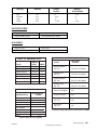
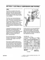
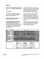
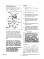
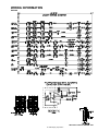
16023083
16023083
INTRODUCTION
The information presented in this manual is printed in a loose format and is divided into
sections relating to a general group of components and/or service procedures. Each
section is further subdivided to describe a particular component or service procedure.
Anything of a unique nature concerning these models has been detailed and labeled as
such in the manual.
The subdividing of the subject matter, plus the loose leaf form will facilitate the updating of the manual as new or revised components are added or new models are introduced.
Each page of the manual will be identified in the lower right-hand corner, and as new or
revised pages are published, the manual can easily be updated by following the file
instructions on the cover letter of the supplement.
The service manual is a valuable tool and care should be taken to keep it up to date by
prompt and proper filing of subsequent pages as they are used.
MODELS COVERED IN THIS MANUAL
DLW231*
PAV2300*
PAV3300*
PAV5000*
PAV5157*
PAV5158*
PAV1000AW*
PAV2000AW*
PAVT344*
HAV2460*
PAVT244*
PAVT234*
HAV2360*
MAV2200*
HAV2557*
HAV2558*
HAV3460*
PAVT444*
HAV4657*
INTRODUCTION
16023083
© 1996 Maytag Corporation
i
16023083
INTRODUCTION
© 1996 Maytag Corporation
ii
CONTENTS
SECTION 1. INSTALLATION ............................................................... 1-1
PRE-INSTALLATION REQUIREMENT .......................................................................... 1-1
Water Supply Requirements .................................................................................. 1-1
Drain Requirements ................................................................................................ 1-1
Electrical Requirements.......................................................................................... 1-2
INSTALLATION PROCEDURE...................................................................................... 1-2
SECTION 2. OUTLINE OF MECHANICAL OPERATION ................... 2-1
CLUTCH ASSEMBLY ................................................................................................... 2-1
AGITATION .................................................................................................................. 2-2
SPIN ............................................................................................................................. 2-2
SECTION 3. CABINET ASSEMBLY COMPONENTS ......................... 3-1
CABINET BODY ASSEMBLY ...................................................................................... 3-1
Front Panel ............................................................................................................. 3-1
Rear Access Panel ................................................................................................. 3-2
TOP ASSEMBLY .......................................................................................................... 3-3
DOOR ASSEMBLY ...................................................................................................... 3-4
CONTROL PANEL ASSEMBLY (PAV1000AWW, PAV2000AWW) ............................ 3-4
Disassembly ........................................................................................................... 3-4
CONTROL PANEL ASSEMBLY (PAV2200, 3200, 4200) ............................................. 3-6
Disassembly ........................................................................................................... 3-6
BASE ASSEMBLY ....................................................................................................... 3-8
STABILIZER ASSEMBLY ............................................................................................. 3-9
SECTION 4. WATER RELATED COMPONENTS ................................ 4-1
WATER MIXING VALVE .............................................................................................. 4-2
WATER INLET FLUME .................................................................................................. 4-3
AIR BELL ...................................................................................................................... 4-3
HOSES ......................................................................................................................... 4-3
TUB TOP ...................................................................................................................... 4-4
AGITATOR (PAV1000AWW, PAV2000AWW) ............................................................ 4-4
AGITATOR (PAV2200, 3200, 4200) ............................................................................. 4-5
SPIN BASKET .............................................................................................................. 4-5
OUTER TUB ASSEMBLY ............................................................................................. 4-6
PUMP ASSEMBLY ....................................................................................................... 4-7
SECTION 5. SUSPENSION SYSTEM (PAV1000AWW, PAV2000AWW) ... 5-1
SUSPENSION SYSTEM (PAV2200, 3200, 4200) ........................................................ 5-2
SUSPENSION HOUSING ............................................................................................. 5-3
TUB BRACES ............................................................................................................... 5-3
SUSPENSION SPRINGS .............................................................................................. 5-3
16023083
CONTENTS
© 1996 Maytag Corporation
iii
SECTION 6. TRANSMISSION AND RELATED COMPONENTS ........ 6-1
CENTER POST ASSEMBLY ........................................................................................ 6-2
BEARING AND SEAL HOUSING .................................................................................. 6-2
TUB SEAL .................................................................................................................... 6-3
SPIN BEARING ............................................................................................................. 6-4
DRIVE PULLEY AND CAMS ........................................................................................ 6-5
BRAKE ASSEMBLY ..................................................................................................... 6-8
TRANSMISSION HOUSING ASSEMBLY..................................................................... 6-10
Oil Seal Replacement ............................................................................................ 6-11
LOWER BEARING ASSEMBLY .................................................................................. 6-11
DIAGNOSING TRANSMISSION PROBLEMS ............................................................. 6-13
SECTION 7. ELECTRICAL COMPONENTS AND TESTING .............. 7-1
TIMER ........................................................................................................................... 7-1
TIMER SEQUENCE CHART ......................................................................................... 7-2
MOTOR ........................................................................................................................ 7-3
MOTOR SWITCH ........................................................................................................ 7-3
MOTOR MOUNTING .................................................................................................... 7-6
MOTOR CIRCUIT TESTING ......................................................................................... 7-7
Overload Protector ................................................................................................ 7-7
Motor Switch ........................................................................................................... 7-8
Motor ...................................................................................................................... 7-8
WATER MIXING VALVE .............................................................................................. 7-8
WATER LEVEL SWITCH .............................................................................................. 7-9
SELECTOR SWITCHES ............................................................................................. 7-11
SAFETY SPIN SWITCH ............................................................................................. 7-11
SECTION 8. SCHEMATIC DIAGRAM ................................................... 8-1
SECTION 9. TROUBLESHOOTING ...................................................... 9-1
16023083
© 1996 Maytag Corporation
CONTENTS iv
SAFETY NOTES
PRECAUTIONS TO BE OBSERVED BEFORE AND DURING SERVICING TO AVOID
POSSIBLE EXPOSURE TO EXCESSIVE DANGER AND ELECTRICAL SHOCK:
1. Disconnect electrical supply before servicing machine.
2. If electricity is required for a test:
(A) First, disconnect electrical supply;
(B) Second, make any connections or adjustments required for the test;
(C) Third, connect electrical supply;
(D) Fourth, perform the test. If service is required, disconnect electrical
supply before servicing machine.
3. Please use caution when servicing the machine with the front panel
removed because there is danger of injury due to potential contact
with spinning transmission.
4. Please use caution when servicing the machine with the front panel
removed because there is danger of injury due to contact with a
potential "pinch point" between the turned up edge of the transmission
cover and the tub support flange.
SAFETY NOTES
16023083
© 1996 Maytag Corporation
v
16023083
SAFETY NOTES
© 1996 Maytag Corporation
vi
SPECIFICATIONS
WASHER WEIGHT
Shipping - 185 pounds approximately
Operating - 160 pounds approximately
DIMENSIONS
Width
Depth
Height to top of cabinet
Height to top of control panel
Height with door open
27"
27"
35 3/4"
44"
53 1/2"
FINISH
Cabinet Top - powdered paint
Clothes Door - powdered paint
Outer Tub - constructed entirely of polypropylene
Basket - polypropylene
Cabinet - baked enamel
Base and other finished parts - baked primer
DRAIN HEIGHT
32 inch minimum
60 inch minimum
MOTOR
3/4 H.P., reversible, 115 volt, 60 cycle A.C.
TRANSMISSION
Rack and pinion type, incorporating reduction gears
16023083
SPECIFICATIONS
© 1996 Maytag Corporation
Vii
Setting
Gallons
Mini
Medium
High
Super
*Allowable variations are plus
*Depth
Inches
10.5
14.1
19.5
23.3
or minus 1/2 inch.
*Basket
Perforations
6"
8 1/2"
11"
13 1/2"
3 1/2"
5"
7"
9 1/4"
AGITATOR SPEED
Regular Cycle
Slow (Delicate) Cycle
90 Oscillations per minute
60 Oscillations per minute
SPIN SPEED
Regular Cycle
Slow (Fine Wash) Cycle
625 R.P.M.
416 R.P.M.
TABLE 0-1. AMPERAGE CHART
CYCLE
Agitate-Regular
Agitate-Slow
Agitate-Regular
Spin-Regular
Spin-Slow
Pump Out-Regular
Pump Out-Slow
WATER
LEVEL
Full Tub
Full Tub
Dry Tub
Dry Tub
Dry Tub
Full Tub
Full Tub
*AMPS
10.4
7.6
7.5
10.2
7.6
10.8
8.0
TABLE 0-2. RESISTANCE CHART
COMPONENTS
Timer Motor
Mixing Valve
Cold Solenoid
Hot Solenoid
Drive Motor
High Speed
Low Speed
Start
*RESISTANCE
(OHMS)
2360
853
867
1.3
2.3
3.1
TABLE 0-2. RESISTANCE CHART
CYCLE
*WATTAGE
RANGE
Agitate-Regular
Full Tub
610-640 / 670 (MAX.)
Agitate-Slow
Full Tub
370-400 / 420 (MAX.)
Agitate-Regular
Dry Tub
460-470 / 480 (MAX.)
Agitate-Slow
Dry Tub
350-360 / 370 (MAX.)
Pump Out-Regular
760
Pump Out-Slow
510
Spin-Regular
Full Tub
460
Spin-Slow
Full Tub
340
* These will vary with washer load and line voltage.
* These values can vary slightly.
SPECIFICATIONS
16023083
© 1996 Maytag Corporation
viii
SPECIAL TOOLS
All special tools are manufactured by Robinaire with the exception of the 35-2442 Brake Removal Tool
and 35-2968 Spanner Wrench - Basket Hub. These tools are privately manufactured for and stocked
by Maytag Customer Service.
NOTE: The tools listed below can be ordered from any authorized Maytag Customer Service parts
distributor.
Transmission Seal Tool, Part Number 14242
Spring Tool Kit, Part Number 21001138
Brake Removal Tool, Part Number 35-2442
Spanner Wrench-Basket Hub, Part Number 35-2968
Motor Test Cord, Part Number 038183
SPECIAL TOOLS
16023083
© 1996 Maytag Corporation
ix
16023083
SPECIAL TOOLS
© 1996 Maytag Corporation
x
16023083
16023083
16023083
16023083
16023083
16023083
16023083
16023083
16023083
16023083
16023083
16023083
16023083
16023083
16023083
16023083
16023083
16023083
16023083
16023083
16023083
16023083
16023083
16023083
16023083
16023083
16023083
16023083
16023083
16023083
SECTION 6. TRANSMISSION AND RELATED
COMPONENTS
This section will detail the servicing procedures on the transmission assembly which
has splines formed on the agitator drive shaft. An "O" ring is installed on the shaft just
above the center post to provide a center post seal when the agitator is installed.
16023083
SECTION 6.
TRANSMISSION AND RELATED COMPONENTS
© 2004 Maytag Services
6-1
CENTER POST ASSEMBLY
REMOVAL:
1. Disconnect the unit from the power
source.
The center post assembly consists of a
plastic center post. A nylon agitator
bearing slips over the lower portion on
the center post body.
2. Remove the agitator, spin basket,
tub assembly, and center post.
The center post assembly is secured to
the basket hub assembly by the spin
basket, and to the agitator shaft. A
small rubber gasket is installed in a
groove on the bottom flange of the center
post, and a foam gasket is placed
between the bottom of the spin basket
and the basket hub assembly.
The center post can be removed after
removing the spin basket, and the agitator shaft "O" ring.
3. Remove the Seal nut with 2202898 and
35-2968
4. Remove the basket hub assembly
by turning it in a counterclockwise direction, using tool number
35-2968.
5. Remove the suspension springs to
prevent damage to the tub braces
and unbolt the tub braces from the
tub support.
6. To remove, lift up on the bearing
and seal housing with tub support
attached.
BEARING AND SEAL HOUSING
The die-cast bearing and seal housing
slips over a machined area on the lower
drive tube. The basket hub assembly
threads downward over the drive tube
and secures the bearing and seal housing.
7. To disassemble tub support from
housing, remove mounting screws
from underside.
The spin bearing and the tub seal are
installed in a cavity in the center of the
housing. The sheet metal tub support is
attached to the under side of the housing
with three (3) mounting screws. The
spin bearing has been pressed into the
underside of the housing cavity and is
secured by the tub support.
The center of the tub assembly mounts to
the upper flange of the housing with a tub
gasket and a tub seal installed between.
The bottom of the tub sits on, and is
attached to, the tub support.
16023083
SECTION 6.
TRANSMISSION AND RELATED COMPONENTS
© 2004 Maytag Services
6-2
TUB SEAL
There are 2 Tub Seal designs, the original
Face Seal and the new Triple Lip Seal
introduced at series 17.
Seal
Face
Face Seal
The tub Face Seal consists of the seal face
and seal body.
Seal
Body
NOTE: All parts of the seal must be
replaced if either of the sealing surfaces
are damaged.
The seal face fits into a recess in the underside of the basket hub assembly. Also, the
seal body installs in the cavity on the top side
of the bearing and seal housing. The spin
bearing is located in a cavity on the underside of the bearing and seal housing.
Each of the two (2) sealing parts, the seal
face and the seal body, have sealing faces
which are brought into contact with one
another when the basket hub assembly is
threaded down on the drive tube. The
springs in the seal body exert pressure to
keep the sealing faces in contact.
Triple Lip Seal
Triple Lip Tub Seal
Assembly used with the
21001867 Hi-Torque
Transmission Assembly.
NOTE: Sealing surface
are on the O.D. of the
aluminum spinner hub
with no seal in the hub
cavity.
NOTE: The Triple Lip Seal and Bearing is only used with the High Torque Dual Drive
transmission. The 21001867 High Torque service transmission will include a Triple Lip Seal and
Bearing for proper matching of parts. The High Torque transmission will have An “HT” next to the date
code for field identification purposes. Do not use 21001868 Seal kit on older transmissions not de
signed to operate at higher torque levels. Always refer to Parts Pro or Microfiche for proper parts
ordering. The 21001868 Triple Lip Seal kit will include a sticker to be placed on the Outer Tub of the
washer to identify the washer has been modified with a High Torque Transmission and Triple Lip Seal
kit.
16023083
SECTION 6.
TRANSMISSION AND RELATED COMPONENTS
© 2004 Maytag Services
6-3
TUB SEAL REPLACEMENT:
Should the tub seal begin to leak or develop
excess seal drag, it must be replaced. The
service replacement seal includes all the
parts necessary to replace the entire seal.
Be sure to replace all parts of the seal even if
only one part is found to be damaged.
TRIPLE LIP SEAL
1. Apply center seal grease (056016) to
Seal Nut and Triple Lip Seal before
installing.
Seal Nut (056016) grease
NOTE: If the tub seal is being replaced
because it has begun to leak, the spin
bearing is probably defective also and
should be replaced. To replace the spin
bearing, the bearing and seal housing
must be removed as previously described. This also allows access to the
tub seal for removal and replacement
(refer to steps 2 and 3 below when installing).
Triple Lip Seal (056016) grease
Removal and replacement of the tub seal
can ONLY be accomplished as follows:
SPIN BEARING REPLACEMENT:
1. Follow steps 1 through 3 for the
face seal
NOTE: For Triple Lip Seal special instuction,
see next column
FACE SEAL
2. Before installing the new seal, coat
the mounting recess of the housings
with silicone grease (part number
203959). This will allow the seal
body and seal face to slip into position.
NOTE: MAKE SURE NO GREASE
COMES IN CONTACT WITH THE
MATING SURFACES OF THE SEAL.
3. Make sure both seal mating surfaces
are free of foreign matter, then clean
both surfaces with an alcohol saturated cloth.
NOTE: Do not use any agent other than
alcohol to clean the mating surface. Do
not use any lubricant other than Silicone
Grease, part number 203959.
16023083
SPIN BEARING
The spin bearing is installed in a cavity on
the underside of the bearing and seal
housing. It is also press fitted and bottoms out on the cavity shoulder. It is
further secured in place by the inner
diameter of the tub support.
1. Disconnect the unit from the power
source.
2. Remove the bearing and seal housing and the tub support as previously described.
3. Remove the seal body from the
housing cavity.
4. Press the spin bearing out of
the cavity from the opposite side of
the housing.
5. When installing the replacement
bearing into the housing cavity, be
sure to press against the outer race
of the bearing to avoid damage to
the bearing shield and causing premature failure.
SECTION 6.
TRANSMISSION AND RELATED COMPONENTS
© 2004 Maytag Services
6-4
DRIVE PULLEY AND CAMS
OPERATION:
The drive pulley and cam is located below
the brake assembly on the drive shaft.
When the drive pulley rotates CLOCKWISE, the upper and lower cams are
designed to nest together which allows
the drive pulley to remain in position on
the drive shaft. The break remains engaged and the drive pulley will turn the
lower cam and drive the shaft to cause
the transmission to agitate.
Models are equipped with a plastic drive
pulley which has the upper cam molded
onto the bottom of the hub. The purpose
of the pulley and cam arrangement is to
drive the clutch assembly during the
agitate and spin cycle, and to disengage
the brake assembly during the spin cycle.
The drive pulley slips over the drive shaft
and rests against a series of washers, a
thrust bearing, and a large washer type
spacer. The spacer locates against the
bottom of the brake rotor and lining
assembly. (See the illustration on
page 6-6.)
The lower cam slips over the end of the
drive shaft where splines formed in the
cam engage with mating splines on the
drive shaft end. This imparts a direct
drive from the cam to the drive shaft.
A shoulder molded on the bottom of the
pulley hub engages "dogs" formed on the
sides of the lower cam, and will drive it
and the drive shaft in either direction.
When the drive pulley rotates COUNTERCLOCKWISE, the upper cam and pulley
ride up the lower cam approximately 3/16
of an inch before the driving shoulders on
the pulley hub engage the "dogs" on the
lower cam.
This causes the top of the pulley hub to
push against the spacer which compresses the brake spring and lifts the
brake rotor and lining assembly off the
brake stator. The brake is disengaged
and the pulley will turn the lower cam
and drive shaft to cause the transmission
to spin.
A washer and retaining ring secure the
pulley and cam on the drive shaft. A
plastic dust cap snaps to the underside
of the pulley to keep the cam surfaces
clean.
16023083
SECTION 6.
TRANSMISSION AND RELATED COMPONENTS
© 2004 Maytag Services
6-5
Original Thrust Washer Design
Spacer
Brake
Stator
16023083
SECTION 6.
TRANSMISSION AND RELATED COMPONENTS
© 2004 Maytag Services
6-6
REMOVAL:
the brake starts to release and the
transmission begins to turn.
(See following figure).
1. Disconnect the unit from the power
source.
2. Tip the unit over and remove the
drive belt.
3. Remove the dust cap from the under
side of pulley.
2. Counting the reference marks on the
lower cam from right to left, the
pulley hub shoulder should be positioned between reference marks 9
and 3, with 6 being the median.
(Shown in the following figure).
4. Remove retaining ring and washer
from end of drive shaft.
5. Firmly pull lower cam off the drive
shaft splines, then slide the other
parts off the shaft. This will also
allow access to the brake assembly
for removal.
REASSEMBLY:
After reassembling the components on
the drive shaft, it will probably be necessary to pull down on the shaft to take the
end play out of it before the thrust washer
and retaining ring can be reinstalled.
NOTE: Each time the cams are reassembled on the drive shaft, the point in
the cam rise where the brake disengages
the stator should be checked and adjusted as necessary.
Reference marks have been molded
around the bottom outer edge of the
lower cam as an aid in checking the point
of brake disengagement (see following
figure). Each mark, from right to left,
represents approximately .010 of an inch
cam rise.
To Check Brake Disengagement:
1. Manually rotate the drive pulley in a
slow counterclockwise direction until
16023083
If the position of the pulley hub shoulder
is not within these parameters and the
brake has started disengaging, adjustment is required.
To Adjust Brake Disengagement:
1. If the position of the pulley hub
shoulder is less than 3 reference
marks, remove the standard (.062
thickness) thrust washer and replace
it with a thinner (.032 thickness)
thrust washer (part number 35-2132).
Recheck disengagement.
2. If the position of the pulley hub
shoulder is more than 9 reference
marks, add a 35-2132 thrust washer
(.032) to the standard thrust washer
and recheck disengagement.
SECTION 6.
TRANSMISSION AND RELATED COMPONENTS
© 2004 Maytag Services
6-7
BRAKE ASSEMBLY
The brake assembly is located inside the
domed area of the suspension housing
and consists of the following components: brake spring retainer, brake
spring, rotor and lining assembly, and
the brake stator.
2. Remove the drive pulley and cam
components as previously described.
3. Using brake removal tool number
35-2442, proceed as follows:
The brake assembly, as well as the snubber, is held in position by the brake stator
which is secured to the underside of the
suspension housing by six (6) mounting
screws.
Spring pressure forces the rotor and
lining assembly down on the brake stator
and prevents the transmission from
turning during agitation.
As stated previously, the drive pulley and
cams provide a cam action which raises
the drive pulley during the counterclockwise (spin) direction of the motor. When
the drive pulley hub travels upward, it
compresses the brake spring and moves
the rotor and lining assembly up the drive
tube disengaging it from the stator. The
transmission is now free to spin.
Splines in the brake rotor hub mesh with
splines on the drive tube end to provide
positive vertical movement for the rotor
and lining assembly. The splines are
greased for ease of movement.
CAUTION
The brake assembly has a compressive spring force of approximately
200 pounds. See the following instructions for disassembly.
• Pull out and remove "U" retainer
from tool.
• Slip the splined end of the drive
shaft into hole located in the tool
inner plunger.
• Looking at the side of the tool,
align slots on tool barrel and holes
in tool plunger between splines
and chamfered shoulder of shaft.
• Slip "U" retainer through tool slots
and holes capturing the drive
shaft behind the chamfered shoulder.
NOTE: Be sure "U" retainer is
completely through both sides of
tool.
• Tighten tool nut to compress
brake spring until transmission
turns freely.
• Remove the six (6) screws which
secure the brake stator and snubber to the underside of the suspension housing.
• Loosen tool nut until the brake
spring reaches its free length.
• Remove "U" retainer from tool and
remove tool from drive shaft.
• Remove brake components.
DISASSEMBLY:
1. Disconnect the unit from the power
source.
16023083
SECTION 6.
TRANSMISSION AND RELATED COMPONENTS
© 2004 Maytag Services
6-8
Min Pulley Hub
Reference
Max Pulley Hub
Reference
Reference Cam
Arrow
16023083
SECTION 6.
TRANSMISSION AND RELATED COMPONENTS
© 2004 Maytag Services
6-9
Rack Gear
Carrier
Transmission
Cover
Rack
Gear
Agitator
Shaft
Cluster
Gear
Output
Pinion
Crank
Gear
Transmission
Housing
Bearing
Housing
Drive
Tube
Input
Shaft
Lower
Seal
16023083
SECTION 6.
TRANSMISSION AND RELATED COMPONENTS
© 2004 Maytag Services
6-10
TRANSMISSION HOUSING
ASSEMBLY
The die-cast aluminum transmission
housing has four studs pressed into its
upper region. The studs provide mounting for the two crank and two cluster
gears. The top cover is threaded into the
lower housing. A sealant is used on the
threads as a gasket material. A steel
drive tube with a splined end is pressed
into the bottom of the transmission housing. A sleeve bearing is installed in the
lower I. D. of the drive tube. Another
bearing is pressed into the lower housing
above the drive tube. These bearings
provide a path for the drive shaft to ride
in. An oil seal is installed in the bottom of
the drive tube. The oil seal can be replaced as a separate part.
Oil Seal Replacement:
The oil seal is located in the spline end of
the drive tube. The seal can be replaced
without removing or disassembling the
transmission, as outlined below:
1. Disconnect the unit from the power
source.
5. Remove the cone-shaped end from
the seal protector tool and slide the
tool, drive washer, and new seal over
the drive shaft up to the seal cavity.
6. Slide the transmission seal driver
(tool number 14242) over the drive
shaft until it makes contact with the
drive washer. Use the impact sleeve
of the tool to "tap" the seal into the
end of the drive tube.
LOWER BEARING ASSEMBLY
The lower bearing assembly consists of a
ball type bearing which has been installed
in an aluminum die-cast housing. The
transmission assembly must be removed
from the washer cabinet before the lower
bearing assembly can be replaced.
The lower bearing assembly provides
lateral support for the drive tube and
shaft against the tension of the drive belt.
The top of the suspension housing
is attached to the underside of the lower
bearing assembly.
REPLACEMENT:
2. Remove the brake assembly to
access the seal.
3. Use a thin, flat bladed screwdriver to
carefully pry the old seal out.
4. Place the drive washer (tool number
14242) and the new seal over
the seal protector.
16023083
SECTION 6.
IMPORTANT
Because the lower bearing assembly
has been pressed onto the drive tube
under approximately 1,000 pounds of
pressure, a puller must be used to
remove it. However, the puller
forcing screw must not be used on
the end of the drive shaft or the
clutch assembly could be damaged.
Instead, a simple pipe and cap assembly can be made to slip over the
drive shaft, with end clearance, and
rest against the end of the drive tube.
TRANSMISSION AND RELATED COMPONENTS
© 2004 Maytag Services
6-11
The puller forcing screw is used on the
end of the pipe cap which directs the
forward thrust of the puller to the bottom
of the drive tube.
REMOVAL:
1. Disconnect the unit from the power
source.
2. Remove the transmission from the
washer cabinet.
3. Remove the cams, drive pulley, and
brake assembly.
5. Slip the pipe and cap assembly over
the drive shaft and up against the
drive tube.
6. Using a puller with at least a 3 1/2
inch spread and sufficient reach to
encompass the pipe and cap assembly, remove the lower bearing assembly.
NOTE: When installing the new lower
bearing assembly, be sure to drive
against the inner race only to avoid
damaging the bearing shield which
could cause premature failure.
4. Remove the three (3) screws which
secure the suspension housing to
the lower bearing assembly.
16023083
SECTION 6.
TRANSMISSION AND RELATED COMPONENTS
© 2004 Maytag Services
6-12
DIAGNOSING TRANSMISSION PROBLEMS
Listed below are most of the service
complaints which would normally be
caused by a malfunctioning component
of the transmission assembly.
Oil Leaks
The Following Torque Tests Will Allow a
Problem in the Spin Drive Train to be
Pinpointed:
Oil leaks can be caused by faulty seals,
gaskets, or a loose fitting stud.
Slow Spin Speed
Slow spin speed can be caused by a
binding tub seal and/or bearing, brake
rotor assembly not disengaging properly,
a slipping clutch spring, or an off balance
clothes load. The test that follows can be
used to isolate the problem.
NOTE: Before starting these tests, the
washer should be operated in the agitation cycle with hot water for about two
(2) minutes, and then for two (2) minutes in a spin cycle. This warms up the
transmission oil and the spin drive train
components.
Available Torque
TORQUE TESTING:
A quick test of the efficiency of the spin
operation components can be made by
placing a 3 1/2 pound weight, such as a
bag of sand, in the washer basket and
starting the machine in the spring cycle.
If the basket appears to reach full spin
with the weight, the machine components are performing as intended. If the
basket does not attain full spin speed, the
torque test procedures as outlined in the
following paragraphs should be performed to determine the problem.
16023083
The torque available to drive the spin
basket is determined by the amount of
drag or resistance presented by the tub
seal and spin bearing, deducted from the
input torque imparted to the transmission
housing assembly by the clutch assembly.
Place a 1/2 inch socket and torque
wrench on the agitator retaining bolt.
Depress the safety spin switch to allow
the washer to operate in the spin cycle,
then while reading the torque allow the
wrench to turn slowly (about 6 R.P.M.)
through a complete 360 degree cycle.
The reading should be between 18 and
25 inch pounds throughout the complete
360 degree rotation of the wrench.
SECTION 6.
TRANSMISSION AND RELATED COMPONENTS
© 2004 Maytag Services
6-13
If the torque readings are within these
limits, the washer is performing properly
and any slow spin complaints can be
assumed to have been the result of offbalance loads.
If the torque reading exceeds 25 inch
pounds, the input torque outlined later
should be checked to determine the
cause. Probable causes are that the drive
shaft is binding in the transmission housing (drive tube) sleeve bearings, or that
the clutch spring is binding on the drive
shaft hub.
If the available torque reading is less than
20 pounds, follow the procedure for
testing the drag torque.
Drag Torque
Position the washer so the drive pulley
can be accessed, and remove the drive
belt. While holding the transmission to
keep it from turning, manually rotate the
drive pulley counterclockwise until the
brake stays disengaged. Make certain
the drive pulley hub shoulder has rotated
fully against the cams in the spin driving
position to ensure the complete disengagement of the brake. Release the
transmission so it is free to turn.
Place a 1/2 inch socket and torque
wrench on the agitator retaining bolt.
Slowly rotate the wrench 360 degrees at
approximately 6 R.P.M. and read the
torque. If the torque reading is over 4
inch pounds, remove the brake stator (as
detailed earlier in this section) and recheck the drag torque.
If the torque reading is now under 4 inch
pounds, the brake is binding and should
be repaired.
16023083
If the reading is still over 4 inch pounds,
the tub seal and/or spin bearing is binding and should be replaced.
If the available torque reading is below
18 inch pounds and the drag torque
reading is not over 4 inch pounds, follow
the procedure for checking the clutch
assembly as to its input torque.
Input Torque
NOTE: It will be observed that the
readings used to check the input torque
are slightly lower than the readings used
to check the available torque. The reason for this is when the brake is disengaged, as in checking the available
torque, the compressed brake spring
exerts a downward force on the bottom
of the clutch hub and thrust washers.
This keeps the clutch spring from slipping quite as readily as in checking the
input torque where the brake is engaged
and the downward force on the clutch
hub is minimized.
To check the input torque, remove the
drive pulley and position the washer so
the scale on the torque wrench can be
read when it is placed on the input (drive)
shaft. Attach the torque wrench adapter
firmly to the shaft, place the wrench in
the adapter and slowly rotate the wrench
in a counterclockwise direction. A properly operating clutch assembly will have a
torque reading between 17 and 20 inch
pounds.
If the input torque is less than 17 inch
pounds, the clutch assembly is defective
and must be repaired or replaced.
If the input torque exceeds 20 inch
pounds, remove the clutch assembly
from the transmission. Secure the drive
SECTION 6.
TRANSMISSION AND RELATED COMPONENTS
© 2004 Maytag Services
6-14
pinion in a vise using two (2) small blocks
of wood to prevent damage to the gear
teeth, and repeat the input torque check.
NOTE: If the "O" ring is to be reused, be
extremely careful not to damage it during the removal.
If the torque reading is between 17 and
20 inch pounds, the drive shaft is binding
in the sleeve bearings.
Remove the center post, "O" ring and
agitator once the drive train is back in
place.
If the torque reading still exceeds 20 inch
pounds, the clutch assembly is defective
and must be repaired or replaced.
The transmission assembly, when removed as described, will have the related
components assembled to it. These
related components should be examined
carefully before reinstalling.
TRANSMISSION REMOVAL:
IMPORTANT
When installing the transmission, it is
necessary that the tub be located on
the tub support a certain way if all the
mounting holes are to be properly
aligned. This should be done before
attempting to mount the tub to the
bearing and seal housing.
The transmission assembly can be removed from the washer cabinet after
removing the drive belt, spin basket,
outer tub and the suspension springs.
NOTE: Be sure to dust the base dome
lightly with cornstarch before installing
the transmission.
CAUTION
Once the agitator has been removed,
the center post slips off the shaft.
Therefore, do not attempt to handle
the drive train by the center post after
the agitator has been removed. Instead, after removing the agitator
and the agitator shaft "O" ring, slip
the center post off the shaft and
handle the drive train by the shaft.
16023083
To assist in correctly positioning the tub, a
small indentation has been formed on the
tub support just above one of the tub
brace mounting areas. This is the left
front tub brace.
When the tub is in proper position and
ready to be mounted to the tub support,
the large tub cover lock (on the side of
the tub) should be located directly above
the indentation and tub brace.
(See the illustration on page 6-14.)
SECTION 6.
TRANSMISSION AND RELATED COMPONENTS
© 2004 Maytag Services
6-15
Large Tub
Cover Lock
Tub
Alignment
Indentation
Tub Support
Left Front
Tub Brace
TUB TO TUB SUPPORT ALIGNMENT
16023083
SECTION 6.
TRANSMISSION AND RELATED COMPONENTS
© 2004 Maytag Services
6-16
16023083
16023083
16023083
16023083
16023083
16023083
16023083
16023083
16023083
16023083
16023083
16023083
16023083
16023083
16023083
16023083
16023083
SECTION 2. WIRING INFORMATION
DLW231
SWITCH AND TIMER SEQUENCE
TO CHANGE TIMER POSITION PUSH KNOB IN AND TURN CLOCKWISE (ALL TIMER CONTACTS WILL OPEN)
C
A
M
P
O
S
0
2
T
U
ADVANCE-EX.RINSE
T
B
AGITATE SELECT
SPRAY RINSE
28-26
28-15TM
4
6
8
T
B
WASH FILL
RINSE FILL
70-71
70-72
T
B
SPIN DIRECTION
7-32
AGITATE DIRECTION 7-8
T
B
AGITATE DIRECTION 9-32
9-8
SPIN DIRECTION
SWITCH FUNCTION
TERM.
IDENT.
DEGREES
10
30
20
40
50
60
70
80
90
100
110
120
130
140
150
160
170
180
190 200
210
220
230
240
250
260
270
280
290 300
310
320 330
340
350
26-17
T
B
15TM-27
P/SW BYPASS
10 TB TM
MOTOR CONTROL NORM 15TM-63
15TM-27
P/SW BYPASS
12 TB TM
MOTOR CONTROL-SLOW 15TM-62
T
BUZZER
15TM-81
INTERVAL NUMBER
1
2
3
4
5
6
7
WASH-REGULAR
16023083
8
P
A
U
S
E
9 10 11 12
SPIN
13 14 15
FILL
AGIT
RINSE
16
P
A
U
S
E
17 18 19 20 21
22
SPIN
23
OFF
24
AGIT
25 26 27 28 29
P
A
U
S
E
30
SPIN
EX-RINSE
31
OFF
32 33 34 35 36
37 38 39 40 41
SPIN
P
A
U
S
E
SPIN
16008333
© 1996 Maytag Corporation
42
A
G P
A
I U
FILL T S
RINSE E
43 44 45 46
47
SPIN OFF
48 49 50
P
A
U
FAST S
AGIT E
51 52 53
54
P
A
FILL
U
SLOW
S
WASH-PERM. PRESS E
55
S
P
R
A
Y
56 57 58 59
SPIN
60
P
A
U
FILL AGIT
S
RINSE E
SECTION 8. CIRCUIT REVIEW
61 62 63
64
65 66
SPIN OFF
8-6
WASH
14 B
WIRING INFORMATION
DLW231
16023083
SECTION 8. CIRCUIT REVIEW 8-7
16008333
© 1996 Maytag Corporation
WIRING INFORMATION
PAV2300
SWITCH AND TIMER SEQUENCE
TO CHANGE TIMER POSITION PUSH KNOB IN AND TURN CLOCKWISE (ALL TIMER CONTACTS WILL OPEN)
C
A
M
P
O
S
0
2
T
U
T
B
AGITATE SELECT
SPRAY RINSE
4
6
T
B
WASH FILL
RINSE FILL
T
B
SPIN DIRECTION
AGITATE DIRECTION
7-32
7-8
8
T
B
AGITATE DIRECTION
SPIN DIRECTION
9-32
9-8
SWITCH FUNCTION
TERM.
IDENT.
DEGREES
10
20
30
40
50
60
70
80
90
100
110
120
130
140
150
160
170
180 190
200
210
220
230
240
250
260
270
280
290
300 310
320 330
340
350
28-26
28-15TM
70-71
70-72
T
B
P/SW BYPASS
15TM-27
10 BT TM
MOTORCONTROLNORMAL15TM-63
15TM-27
P/SW BYPASS
12 TB TM
MOTORCONTROL-SLOW 15TM-62
14 B
T
1
2
3
4
5
6
7
8
9
10
11
12 13
14
P
A
WASH-REGULAR
U
S
E
FILL
SPIN
AGIT
RINSE
15
P
A
U
S
E
16 17
18 19
SPIN
20
21
OFF
22
23
24
25 26
27
WASH-GENTLE
28
P
A
U
S
E
29
30
SPIN
31 32 33
34
P
A
U
FILL AGIT
S
RINSE E
35 36 37
38
39
SPIN OFF
40
41 42 43
P
A
U
S
NORM. SPD. E
44
45
46
SLOW SPD.
WASH-PERM. PRESS
47
P
A
U
S
E
48
S
P
R
A
Y
49
SPIN
50
51
FILL
52
53
AGIT
RINSE
54
P
A
U
S
E
55
56
57
58
59
SPIN OFF
60
WASH
INTERVAL NUMBER
16023083
16008333
© 1996 Maytag Corporation
SECTION 8. CIRCUIT REVIEW 8-8
WIRING INFORMATION
PAV2300
16023083
16008333
© 1996 Maytag Corporation
SECTION 8. CIRCUIT REVIEW 8-9
WIRING INFORMATION
PAV3200
SWITCH AND TIMER SEQUENCE
TO CHANGE TIMER POSITION PUSH KNOB IN AND TURN CLOCKWISE
C P
A O
M S
SWITCH FUNCTION
TERM.
IDENT.
0 UL LINESWITCH/PUSHOFF26-12
5
10
5
10
15
STEP INCREMENTS
20
25
30
35
20
25
30
35
40
45
50
45
50
55
60
65
55
60
65
WASH FILL
70-71
70-72
RINSE FILL
RINSE
28-15TM
4 UL SPRAY
AGITATE SELECT 28-26
TM.P.SW.BYPASSSPIN 15TM-27
6 UL MOTORCONTROLAGITATE15TM-6
3
DIRECTION7-32
9 UL SPIN
AGITATE DIRECTION 7-8
1 LU
8 UL MOTORCONTROLSPIN15TM-62
AGITATE DIRECTION
13 L SPIN
DIRECTION 9-8
U
9-32
ADVANCE TO WASH
14 UL M
TR. CONT. SOAK SPIN 26-17
26-16
U
L
MINUTES
WASH
4
S
P
R
A
Y
15
F
I
L
L
P
A
U
S
E
SPIN RINSE SPIN
REGULAR CYCLE
APAPAPAP
GA GA GA GA
I UI UI UI U
T T T T
AS AS AS AS
TE TE TE TE
E E E E
WASH
S
P
R
A
Y
SPIN
20 16 12 8
P
A
U
S
E
F
I
L
L
P
A
U
S
E
40
R
I
N
S
E SPIN
SHORT CYCLE
16023083
16008333
© 1996 Maytag Corporation
AA
GG
I I
TT
AA
TT
EE
SOAK
A
G
I
T
A
T
E
SOAK
AP
GA
I U
T
AS
TE
E
SPIN
P
A
U
S
E
SOAK CYCLE
ADVANCE TO WASH
SECTION 8. CIRCUIT REVIEW 8-10
WIRING INFORMATION
PAV3200
16023083
16008333
© 1996 Maytag Corporation
SECTION 8. CIRCUIT REVIEW 8-11
WIRING INFORMATION
PAV3300
SWITCH AND TIMER SEQUENCE
TO CHANGE TIMER POSITION PUSH KNOB IN AND TURN CLOCKWISE (ALL TIMER CONTACTS WILL OPEN)
C
A
M
P
O
S
SWITCH FUNCTION
TERM.
IDENT.
0
2
T
U
ADVANCE-WASH
ADVANCE-2ND RINSE
26-16
26-17
T
B
4
6
T
B
AGITATE SELECT
SPRAY RINSE
WASH SELECT
RINSE SELECT
T
B
SPIN DIRECTION
AGITATE DIRECTION
8
10
12
T
B
AGITATE DIRECTION
SPIN DIRECTION
T
B
SPIN SOAK
MOTOR CONTROL SPIN
15TM-69
15TM-62
T
B
TM P/SW BYPASS S
MOTOR CONTROL-AGIT
15TM-27
15TM-63
14
T
B
BUZZER
15TM-81
DEGREES
10
30
20
40
50
60
70
80
90
100
16
17 18 19
20
110
120
130
140
150
160
170
180
190
200
210
220
230
240
250
260
270
280
290
300
310
320
330
340
350
63 64 65
66
28-26
28-15TM
70-71
70-72
7-32
7-8
9-32
9-8
T
B
2
3
4
5
6
16023083
WASH-REGULAR
7
8
P
A
U
S
E
9 10
11
12 13 14
FILL
SPIN
AGIT
RINSE
15
P
A
U
S
E
SPIN
21
22
23
AGIT
P
A
U
S
E
24 25
26
27
28
29 30
31 32 33
34
SPIN
EXTRA RINSE
OFF WASH-PERM. PRESS
35
P
A
U
S
E
36
S
P
R
A
Y
SPIN
37
38
39
FILL
A
G
I
T
RINSE
16008333
© 1996 Maytag Corporation
40
P
A
U
S
E
41 42 43
SPIN
44
45
OFF
1
OFF
INTERVAL NUMBER
46
AGIT
47
48 49 50
51 52 53
54
55
56 57 58 59 60 61
A
G
I
T
SOAK - ADVANCE TO WASH
62
P
A
G U
I S
T E
67
A
SPIN
PAUSE
SECTION 8. CIRCUIT REVIEW 8-12
WIRING INFORMATION
PAV3300
16023083
16008333
© 1996 Maytag Corporation
SECTION 8. CIRCUIT REVIEW 8-13
WIRING INFORMATION
CONNECTION
DIAGRAM
TIMER
KNOB-PUSH OFF
PAV5000
REDBLK 16
DOOR SW.
N.O.
LINE VOLTAGE
SERVICE CORD
GND.
12
17
GRN
26
TAN
28
LT. BLUE
YELLOW-RED
27
TAN
LT. BLUE
63
15
LT. BLUE
ADVANCE TO
RINSE SWITCH
YEL-BLK
62
WH-BRN
EMPTY
P
65
67
81
6PM
GRN-BLK
66
5
SPEED
SELECTOR
SWITCH
FULL
1
2
MOTOR
64
WH-PUR
69
15
GRAY
GND
W
H
I
T
E
15
3
TIMER
MOTOR
WATER
LEVEL
SWITCH
32
1
START
YELLOW
BUZZER
RED
7
8
4PM
3
4
32
* CAPACITOR
YELLOW
BLUE
9
2
WHITE-YELLOW
8
WHITE
WHITE
WHITE-RED
17
16
71
7O
ORANGE
21
COLD
20
19
WHITE-RED
1
20
6
18
72
3
RED
43
GRAY
8
GRAY
7 11
PINK
10
HOT
21
PINK
2O
4
W
H
I
T
E
WHITE-YEL.
WHITE-BLUE
WATER
VALVE
PURPLE
PURPLE
SPEED SELECTOR SWITCH
POSITION
WASH SPEEDS
POSITION
CIRCUIT
64-66 67-66
CIRCUIT
H-C
17-19-16, 18-43
W-C
17-16-19-20, 18-43
C-C
17-16-20, 18-43
N-S
64-66 67-65
S-N
64-65 67-66
ATCW-W
S-S
64-65 67-65
ATCW-C
17-20-19, 18-43
ATCC-C
17-20, 18-43
WATER
TEMPERATURE
SWITCH
TEMPERATURE
CONTROL
35-6345 "B"
17-18-19-20
SWITCH AND TIMER SEQUENCE
TO CHANGE TIMER POSITION PUSH KNOB IN AND TURN CLOCKWISE (ALL TIMER CONTACTS WILL OPEN)
C
A
M
P
O
S
SWITCH FUNCTION
TERM.
IDENT.
0
2
4
6
8
T AGITATE DIRECTION
B SPIN DIRECTION
9-32
9-8
10
12
14
T SPIN SOAK
B MOTOR CONTROL SPIN
15TM-69
15TM-62
T TM P/SW BYPASS S
B MOTOR CONTROL-AGIT
15TM-27
15TM-63
T BUZZER
B
15TM-81
T AGITATE SELECT
B SPRAY RINSE
T WASH SELECT
B RINSE SELECT
T SPIN DIRECTION
B AGITATE DIRECTION
DEGREES
10
30
20
40
50
60
70
80
90
100
110
120
130
140
150
160
170
180
190
200
210
220
230
240
250
260
270
48
50
280
290
300
310
56
58
320
330
340
350
26-16
26-17
T
U ADVANCE-2ND RINSE
28-26
28-15TM
70-71
70-72
7-32
7-8
T
B
INTERVAL NUMBER
1
2
3
4
5
6
WASH-REGULAR
7
8
P
A
U
S
E
9
10
11
12 13
FILL
SPIN
14
A G IT
RINSE
15
P
A
U
S
E
16
17 18
19
20
21
22
AGIT
SPIN
23
P
A
U
S
E
24
25
26
27
28
29
30 31
32
33
34
SPIN
OFF EXTRA RINSE
OFF WASH-PERM. PRESS
35
P
A
U
S
E
36
37
S
P
R
A
Y
SPIN
38
39
A
G
I
FILL T
RINSE
40
41 42
43
44
45
46
47
49
51
52
53
54
55
57
A
P
A
U
S
E
AGIT
S P IN
OFF
G
I
T
SOAK - ADVANCE TO WASH
59 60
61
62
A
G
I
T
P
A
U
S
E
63
64 65
66
67
S P IN
PAUSE
16023083
16008333
© 1996 Maytag Corporation
SECTION 8. CIRCUIT REVIEW 8-14
WIRING INFORMATION
PAV5000
L1
B
L
TIMER
TIMER
26
63
64
65
1
3
15
WATER
SPEED
TIMER
TIMER
WH.-PUR. SW.
YEL
GRAY LEVEL LT.BLU
26
28
1
3
15
DOOR
TIMER
TIMER
SWITCH
BRN.
BRN.
12
26
12
TIMER
12
26
TIMER
12
DOOR
SWITCH
BRN.
27
BRN.
TIMER
BRN.
GRAY
26
12
TIMER
BRN.
28
DOOR
SWITCH
15
TIMER
MP
WHT-YEL
COLD
W.S.
21
WHITE
TIMER
15
MP
12
17
DOOR
SWITCH
5
BLU.
MP
WH.
MP
WH.
32
START-MOTOR
RED
4
TIMER
32
SPEED
SW.
GRN-BLK
65
YELLOW
TIMER
26
15
27
PINK
11 10
TIMER
9
8
7
6
5
3
2
4
TEMPERATURE CONTROL
BOARD
17
12
16
YEL-RED BLK RD-BLK
28
26
LT-BLU
LT-BLU GRAY BRN
16
12
17
RD-BLK BLK YEL-RED
26
28
LT-BLU
GRAY LT-BLU
BRN
72
70
71
WH-BLU ORANGEWH-RED
71
70
72
WH-RED ORANGE WH-BLU
WHITE
WHITE
62
WH-BRN
63
WH-PUR
7
32
YEL
RED
9
32
BLUE
YEL
RD-BLK
69
LT-BLU YEL-BLK
15 TM
27
LT-BLU BRN
81
TAN
FRONT TIMER PLATE
= NOT USED.
WH.
TIMER
WHTTM
YEL P
8
TIMER
WHTTM
8 YEL P
TIMER
WHTTM
8 YEL P
BUZ
TIMER
WHTYEL P
8
P
MP
WH.
P
MP
WH.
P
MP
WH.
P
MP
WH.
P
* CAPACITOR USED WITH ALTERNATE
CAPACITOR START MOTOR.
RUN
WHITEYELLOW
MP
P
TAN
4
WH.
P
1
81
15
MP
MOTOR
TIMER
LT.-BLUE
P
1
3
GRN-BLK
15
TIMER ADVANCE
RINSE SWITCH
WH.
WHT8 YEL P
P
TIMER
TIMER
P
MP
TIMER
65
15
WH.
WHT8 YEL P
9
MOTOR
7
YEL.
67
66
SPEED
SW.
BLU.
2
P
MP
TIMER
7
LT.-BLUE
TIMER
P
1
RED
4
2
15
BRN.
P
1
3
START-MOTOR
TIMER
67
15
WH.
P
8
MOTOR
P
WH-BRN
62
P
WHT-YEL
MOTOR
67
65
SPEED
SW.
WH-BRN
WH.
P
8
GRN-BLK
WH-BRN
YEL-RED
GRAY
12
TIMER
P
3
27
BRN.
WHITE
32
32
9
SPEED
TIMER
SW.
YEL
62
TIMER
TIMER
66
62
15
TIMER
B
L
K
TIMER
TIMER
15
1
26
64
15
27
15
WATER
LEVEL
BRN.
63
TIMER
27
26
TIMER
12
DOOR
SWITCH
BRN.
21
28
WHITE
BUZZER
63
64
66
1
3
15
WATER
SPEED
TIMER
TIMER
GRAY LEVEL LT.BLUE
WH.-PUR. SW.
28
WHITE/RED, D/STRIPE
T.M. ADVANCE
TO RINSE
26
12
VIOLET
B
L
MOTOR SPIN K
FAST
B
L
MOTOR SPIN K
SLOW
B
L
K
T.M.
AGITATE
B
L
K
T.M.
SPIN
TIMER
RED
MOTOR START
SPIN
B
L
K
12
W.S.
28
WHITE/YELLOW, D/STRIPE
AGITATE
TIMER
TIMER
HOT
22
70
71
17
19
1
2
10
4
WATER
WATER
TEMP. CONT. BOARD
TIMER
TEMP. SW.
TIMER
LEVEL
PURPLE
GRAY
WH.-RED
ORANGE
WH.-YEL.
20
71
26
28
1
2
70
17
20
9
3
WATER
SPEED
TIMER
TIMER
TIMER
YELLOW
GRAY LEVEL LT.BLUE
WH.-PUR. SW.
YELLOW
12
12
WATER
TEMP. CONT. BOARD
TEMP. SW.
PINK
PINK
WH.-RED
CLOSED UP
B
L
MOTOR AGIT. K
FAST
B
L
MOTOR AGIT. K
SLOW
B
L
MOTOR STARTK
26
WATER
LEVEL
TIMER
ORANGE
GRAY
GRAY
WASH FILL
COLD WATER
B
L
K
TIMER
PINK
WASH FILL
HOT WATER
N
LINE VOLTAGE
LADDER WIRING DIAGRAM
32
7
WHITEYEL
RED YELLOW
32
9
WHITE
BLUE WHITE
YEL
69
RD-BLK 62
YEL-BLK LT-BLU WH-BRN
27
15 TM
63
BRN LT-BLU WH-PUR
81
TAN
START
V
1
3
2
G
P
5
K
BL
R
PU
T
WH
YEL
ORANGE
SCHEMATIC
AUX
BLUE
4P MAIN
RED
4
EMERSON
6P MAIN
PROT
4
RED
5
P
G
2
3
1
V
GREEN-BLACK
WHITE
GREEN
BLUE
YELLOW
WHITE-YELLOW
HARNESS PLUG
CONNECTOR END
16023083
16008333
© 1996 Maytag Corporation
SECTION 8. CIRCUIT REVIEW 8-15
WIRING INFORMATION
PAV5157, PAV5158
SWITCH AND TIMER SEQUENCE
TO CHANGE TIMER POSITION PUSH KNOB IN AND TURN CLOCKWISE (ALL TIMER CONTACTS WILL OPEN)
DEGREES
C P
TERM.
10
A OSWITCH FUNCTION IDENT.
MS
ADVANCE-WASH
T
26-16
0 U ADVANCE-2NDRINSE 26-17
T
SELECT 28-26
2 B AGITATE
SPRAY RINSE 28-15TM
T WASH SELECT 70-71
4 B RINSE SELECT 70-72
20
30
40
50
60
70
80
90
100
110
120
130
140
150
160
170
180
190
200
210
220
230
240
250
260
270
280
290
300
310
320
56 57
58 59 60 61
330
340
350
63 64 65
66
SPIN DIRECTION 7-32
6 T
B AGITATEDIRECTION 7-8
GITATE DIRECTION 9-32
8 TB A
SPIN DIRECTION 9-8
15TM-69
SOAK
10 TB SPIN
MOTORCONTROLSPIN 15TM-62
P/SW BYPASS S 15TM-27
12 TB TM
MOTORCONTROL-AGIT 15TM-63
14 TB BUZZER
15TM-81
T
B
*120 SECONDS
PER INTERVAL
16023083
16008333
1
2
3
4
5
6
7
WASH-REGULAR
8
P
A
U
S
E
9
10
11
12 13 14
FILL
SPIN
AGIT
RINSE
15
P
A
U
S
E
16 17 18 19
20
21
22
AGIT
SPIN
OFF
23
P
A
U
S
E
24
25 26
27
28
29 30
31 32 33
34
SPIN
EXTRA RINSE
OFF WASH-PERM. PRESS
35
P
A
U
S
E
36
37
S
P
R
A
Y
SPIN
38
39
A
G
I
FILL T
RINSE
© 1996 Maytag Corporation
40
P
A
U
S
E
41 42
43
SPIN
44
45
OFF
* INTERVAL NUMBER
46
AGIT
47
48 49 50
51 52 53
54
55
A
G
I
T
SOAK - ADVANCE TO WASH
62
A
G
I
T
P
A
U
S
E
67
SPIN
PAUSE
SECTION 8. CIRCUIT REVIEW 8-16
WIRING INFORMATION
PAV5157, PAV5158
16023083
16008333
© 1996 Maytag Corporation
SECTION 8. CIRCUIT REVIEW 8-17
WIRING INFORMATION
PAVT344
16023083
16008333
© 1996 Maytag Corporation
SECTION 8. CIRCUIT REVIEW 8-18
WIRING INFORMATION
PAVT344
16023083
16008333
© 1996 Maytag Corporation
SECTION 8. CIRCUIT REVIEW 8-19
WIRING INFORMATION
HAV2460
16023083
16008333
© 1996 Maytag Corporation
SECTION 8. CIRCUIT REVIEW 8-20
WIRING INFORMATION
HAV2460
16023083
16008333
© 1996 Maytag Corporation
SECTION 8. CIRCUIT REVIEW 8-21
WIRING INFORMATION
PAVT244
16023083
16008333
© 1996 Maytag Corporation
SECTION 8. CIRCUIT REVIEW 8-22
WIRING INFORMATION
PAVT244
16023083
16008333
© 1996 Maytag Corporation
SECTION 8. CIRCUIT REVIEW 8-23
WIRING INFORMATION
PAVT234, HAV2360, MAV2200
16023083
16008333
© 1996 Maytag Corporation
SECTION 8. CIRCUIT REVIEW 8-24
WIRING INFORMATION
PAVT234, HAV2360, MAV2200
16023083
16008333
© 1996 Maytag Corporation
SECTION 8. CIRCUIT REVIEW 8-25
WIRING INFORMATION
HAV2557/2558
16023083
16008333
© 1996 Maytag Corporation
SECTION 8. CIRCUIT REVIEW 8-26
WIRING INFORMATION
HAV2557/2558
16023083
16008333
© 1996 Maytag Corporation
SECTION 8. CIRCUIT REVIEW 8-27
WIRING INFORMATION
HAV3460
16023083
16008333
© 1996 Maytag Corporation
SECTION 8. CIRCUIT REVIEW 8-28
WIRING INFORMATION
HAV3460
16008333
© 1996 Maytag Corporation
SECTION 8. CIRCUIT REVIEW 8-29
WIRING INFORMATION
PAVT444, HAV4657
16023083
16008333
© 1996 Maytag Corporation
SECTION 8. CIRCUIT REVIEW 8-30
WIRING INFORMATION
PAVT444, HAV4657
16023083
16008333
© 1996 Maytag Corporation
SECTION 8. CIRCUIT REVIEW 8-31
16023083
SECTION 8. CIRCUIT REVIEW 8-32
16023083
16023083
16023083
16023083
16023083
16023083
16023083
SECTION 9. TROUBLESHOOTING 9-8
16023083
SECTION 9. TROUBLESHOOTING 9-9
TEMPERATURE CONTROL BOARD
Model: PAV5000
The temperature control board receives information from
the water temperature switch about the user’s water
selections. The thermistor located in the water valve,
provides inputs to the board, as it detects the incoming
water temperature. This information combined with the
selections on the temperature control switch determine
the output signals to the water valve. The target cold
temperature is 75° F, ± 5° F. The target warm temperature
is 95° F, ± 5° F. The temperature control system is
intended to warm wash fills when necessary to the target
temperature. It will not cool a fill when the inlet temerature
exceeds the minimum target temperature.
The analog board monitors the water temperature and will
turn the valves ON and OFF to maintain proper water
temperature. When the water temperature is set on
WARM, both valves are on. The longer the valve is ON,
the lower the water temperature will drop in the water
lines. As the temperature drops the automatic temperature control will cycle the water valve to maintain the
proper water temperature. Rinse fills are not temperature
controlled unless warm rinse is selected.
The analog automatic temperature control (ATC) table
depicts the philosophy of how the automatic temperature
control board operates. The thermistor temp represents
the temperature sensed by the thermistor in the water
valve. The outputs are indicative of the board sending
voltage to the water valve solenoids.
Note:
With the temperature control selector in the
ON position.The only combinations where
the temperature control board is active
(BOLD) are warm and cold.
When cold is selected and the temperature sensed by
the thermistor is too low at the valve, the hot valve will be
activated.
When warm is selected and the temperature sensed by
the thermistor is too cool, the cold valve will be shut off.
Analog Automatic Temperature Control (ATC) Table
Water Temp
Selections
Hot
Warm
Cold
Hot
Warm
Cold
Hot
Warm
Cold
Hot
Warm
Cold
ATC Selector
Off
Off
Off
Off
Off
Off
On
On
On
On
On
On
Thermistor
Temp
Low
Low
Low
High
High
High
Low
Low
Low
High
High
High
Hot Valve
Output
On
On
Off
On
On
Off
On
On
On
On
On
Off
Cold Valve
Output
Off
On
On
Off
On
On
Off
Off
On
Off
On
On
16023083
16008333
© 1996 Maytag Corporation
SECTION 9. TROUBLESHOOTING 9-10
RED
WHITE/RED, D/STRIPE
8
7
6
Analog Temperature Control Board Diagnostics
Chart
PIN
SOURCE
OUTPUT/INPUT
WIRE COLOR
1
2
Neutral
Not Used
Cold
Valve
Hot Valve
Timer (12
T Contact)
Input
3
4
6
4
3
2
4
TEMPERATURE CONTROL
BOARD
WHITE
MEASURE
TO PIN #
Line
VOLTS
OHMS
120VAC
Output
VIOLET
1
120VAC
Output
PINK
WHITE/RED,
D/STRIPE
1
120VAC
1
120VAC
Input
5
WHITE
GRAY
9
CLOSED UP
WHITE/YELLOW, D/STRIPE
10
VIOLET
PINK
11
Analog Temperature Board Tests
To test the temperature board for proper function, use the
diagnostics chart below in conjunction with the 11 terminal pin connector and an ohm meter.
PINK
GRAY
TEMPERATURE CONTROL BOARD
OVDC
324VDC
10K100K
OHMS
CONDITIONS
Wash Cycle on Timer
TC Option Deselected
TC Option Selected
7
TC
Disable
Input
RED
6
8
Thermistor
Input
GRAY
11
Input
WHITE/YELLOW,
D/STRIPE
6 * **
OVDC
Warm or Cold Wash
Selected
Input
PINK
6 * **
OVDC
Hot or Warm Wash
Selected
Input
GRAY
8
10K100K
OHMS
Room Temperature
9
10
11
Temp
Selector
Switch
Cold
Wash
Temp
Selector
Switch Hot
Wash
Thermistor
Room Temperature
* Reference DC voltages to line 1.
** Temperature only occurs during cold or warm wash
fills.
16023083
16008333
SECTION 9. TROUBLESHOOTING 9-11
© 1996 Maytag Corporation
16023083