1
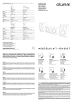
TM
Owners' Manual
TM
Introduction
Contents
Introduction
.........2
Safety Precautions
.........3
Components
.........4
Subwoofer Controls
.........4
Connecting Your Loudspeakers
.........6
Positioning Your Loudspeakers
.........6
Please read and retain this manual, it contains useful
information that will ensure you get the very best from
your new loudspeakers.
Attaching Feet to Your Ms308
.........8
Final Setup
.........8
Note:
Model MS308 is supplied in two mains voltage
ratings. Please refer to product rear panel
Taking Care of Your Loudspeakers
..........9
Specifications
........10
Warranty Information
........11
This Premiere Home Theatre multi-channel
loudspeaker system is the result of an extensive
Research and Development programme
undertaken to provide you with surprisingly full
and accurate performance from such small
enclosures.
With attention to detail second to none, these
loudspeakers not only guarantee outstanding
enjoyment but their elegant, clean lines also allow
them to integrate easily into your home.
2
Safety Precautions
For safety reasons please read the following instructions and the enclosed
Important Safety Information carefully before attempting to connect your
subwoofer unit to the mains.
Warning
To reduce the risk of fire or electric shock, do not expose this appliance to
rain or moisture.
Caution
Use of controls or adjustments or performance of procedures other than
those specified may result in hazardous radiation exposure.
Plug Fitting Instructions (UK only)
The cord supplied with this appliance is factory fitted with a 13A mains plug
fitted with a 3A fuse inside. If it is necessary to change the fuse, it is
important that a 3A one is used. If the plug needs to be changed because it
is not suitable for your socket, or becomes damaged, it should be cut off
and an appropriate plug fitted following the wiring instructions below. The
plug must then be disposed of safely, as insertion into a 13A socket is likely
to cause an electrical hazard. Should it be necessary to fit a 3-pin BS
mains plug to the power cord the wires should be fitted as shown in this
diagram. The colours of the wires in the mains lead of this appliance may
not correspond with the coloured markings identifying the terminals in your
plug. Connect them as follows:•
Caution
To reduce the risk of electric shock, do not remove cover (or back). There
are no user-serviceable parts inside. Please refer all servicing to a
qualified engineer.
The lightning flash with the arrowhead symbol within an
equilateral triangle is intended to alert the user to the presence
of uninsulated ‘dangerous voltage’ within the product’s
enclosure that may be of sufficient magnitude to constitute a
risk of electric shock to persons.
The exclamation point within an equilateral triangle is intended to
alert the user to the presence of important operating and
maintenance (servicing) instructions in the literature
accompanying the appliance.
This product complies with European Low Voltage
(73/23/EEC) and Electromagnetic Compatibility
(89/336/EEC) Directives when used according to this
instruction manual.
The 110V version of the MS308 complies to the requirement
ANSI/UL STD.1492, is certified to CAN/CSA STD.C22.2
NO.1 and is approved by ETL for sale in the USA and Canada
The wire which is coloured BLUE
must be connected to the terminal
which is marked with the letter ‘N’
or coloured BLACK.
GREEN /
YELLOW
E
FUSE
•
The wire which is coloured BLUE
BROWN must be connected to the
N
terminal which is marked with the
letter ‘L’ or coloured RED
L
BROWN
•
The wire which is coloured
GREEN/YELLOW must be
connected to the terminal which is
marked with the letter ‘E’ or
coloured GREEN.
CORD
GRIP
Note
If a 13 Amp (BS 1363) type of plug is used a 3 Amp or 5 Amp fuse must be
fitted, either in the plug or adaptor, or on the distribution board.
3
Components in your System
Subwoofer Controls
MS302
Front Left and Right and
Rear Left and Right
Loudspeakers
1. Phase
Selects subwoofer output to be either in or out of phase
(180 degrees). This allows you to optimise the phase of
your MS308 to different listening positions and that of other
speaker systems used at the same time.
2. Volume
MS304
Centre
Channel
Loudspeaker
32
1
LOW FREQUENCY
CUT-OFF
POWER
VOLUME
PHASE
7
0
180
50Hz
ON
AUTO
MIN
150Hz
MAX
OFF
+
+
L
LEFT
RIGHT
LEFT
RIGHT
LINE IN
R
5
POWER
O
l
OFF
4
FROM AMPLIFIER
ON
6
-
REPLACE WITH FUSE TO BS4265/IEC127
FUSE T1A 250V
TO SATELLITE SPEAKERS
4
MS308
Subwoofer
This control allows you to adjust the volume of low
frequency output from your subwoofer amplifier to obtain
the best sound-balance within your surroundings
3. Low Frequency Cut-Off
This is used to adjust the point at which the crossover will
separate the low frequencies being used by the subwoofer
from the higher frequencies played by the rest of the
system. Raising the Low Frequency Cut-Off will increase
the frequency range that the MS308 will reproduce.
Lowering the Low Frequency Cut-Off will limit the range of
frequencies reproduced.
4. High Level Input / High Level Output
If your amplification system does not have a dedicated
subwoofer line output, your subwoofer must be connected
via the high level terminals on the rear panel. Connection
should be made from the speaker terminals on your
amplification system to the High Level Input Connections
Subwoofer Controls
(taking care to observe polarity). A second set of cables
may then be run from the High Level Output connections to
your front left and right loudspeakers (see Fig. 1 below).
5. Line Input
If your amplification system has a dedicated subwoofer line
output it should be connected here (see fig 2. below).
6. Power
Switches the subwoofer (amplifier) power on or off.
Note: This vacation switch is used to disconnect power
from the product during long periods of non-use
VOLUME
CUT-OFF
ON
AUTO
MIN
150Hz
to satellite
loudspeakers
MAX
OFF
++
+
L
LEFT
LINE IN
R
-
RIGHT RIGHT
LEFT
LEFT
RIGHT
RIGHT
-
--
FROM AMPLIFIER
From
amplifier
dedicated
subwoofer
line output
ON
O
l
OFF
AUTO
MIN
150Hz
MAX
OFF
++
+
L
LEFT
LINE IN
R
-
RIGHT RIGHT
LEFT
LEFT
RIGHT
RIGHT
-
--
FROM AMPLIFIER
TO SATELLITE SPEAKERS
TO SATELLITE SPEAKERS
POWER
POWER
ON
VOLUME
CUT-OFF
50Hz
FIG. 1
ON
OFF
O
50Hz
If switched to auto, the subwoofer will remain in standby
mode until a signal is detected at the input. The unit will
then automatically switch itself on. It will then automatically
return to standby mode if no input signal is present for
approximately 5 minutes. With the switch in the 'ON'
position the unit remains permanently on as long as the
main power switch is on. The LED positioned on the rear
panel indicates whether the unit is on or in standby mode
(red for standby and green when on). The blue front panel
LED indicates the unit is on and working.
l
from amplifier
loudspeaker
connections
7. Auto/On
FIG. 2
To prevent damage to the amplifier, only connect using high-level inputs OR line level inputs:
DO NOT USE BOTH METHODS OF CONNECTION AT THE SAME TIME
5
Getting Started
Connecting your Loudspeakers
Important note
Do not compromise the performance of your system by
using inferior quality cables! Mordaunt-Short recommends
that high quality cables of 16 gauge or higher be used.
Your professional dealer will give you good advice.
Observing polarity is of the utmost importance while
connecting your loudspeakers. Ensure that the red (+)
terminals on your amplification system are connected to
the red (+) on the speaker, and black (-) on your
amplification system to black (-) on your speakers.
If your speakers are wired incorrectly they will be out of
phase and sound hollow and indistinct, with a weak bass.
Re-check your connections for correct polarity and reverse
the connections if necessary.
Always unplug all A.C. powered components before
making any loudspeaker or component connections. This
will avoid the risk of electric shock or damage to your
equipment.
Positioning your Loudspeakers
Properly placed, your Mordaunt-Short Premiere
loudspeaker system will provide an excellent, wholly
satisfying sound. However, with each room varying in size,
dimension and layout, it will be necessary to experiment
with the placement of your loudspeakers in order to gain
optimum performance. A typical set-up is shown below.
1. MS302 Front
1
3
1
2. MS302 Rear
-
+
3. MS304 Centre
2
2
4
6
4. MS308 Subwoofer
Getting Started
MS302 Front Left and Right Loudspeakers
Your MS302 front left and right speakers should be placed
equidistant to the left and right of your screen far enough
apart to ensure good stereo imaging. If they are too far
apart or too close to the corners of the room they will sound
distracting and distant. It may be desirable to experiment
with the 'toe-in' of the units (angling them towards the
listening position) to optimize the front speaker soundstage
and imaging.
MS302 Rear Left and Right Loudspeakers
Your MS302 rear left and right speakers should be situated
roughly at listening height and facing into the listening
position. It is suggested that they are wall mounted or
alternatively placed on suitable speaker stands.
MS304 Centre channel Loudspeaker
Your MS304 centre channel speaker needs to be
positioned directly above or below your screen, facing the
listening position.
Note
Your MS302 loudspeakers come with mounting holes to fit
Omnimount 25 Series wall mountable speaker brackets.
Details are available at www.omnimount.com.
Mordaunt-Short brackets are also available, contact your
dealer or www.mordaunt-short.co.uk for more information.
MS308 Subwoofer
The positioning of your MS308 subwoofer will affect the
quantity and also quality of the lower frequencies of the
system. Locating the subwoofer near a wall will increase
the bass response of the speaker. If it is placed too near to
a corner however, the overall effect may be too 'boomy'.
Due to the low frequency nodal characteristics of the room,
the response will change as it is placed a little closer, or
further away from the listening position. Adjusting the rear
panel controls (as explained in previous sections) will also
affect the sound, so the answer is to experiment and find
the position and settings that provide a good balance
between low frequency amount and definition across a
range of source material.
7
Getting Started
Attaching feet to your subwoofer
Final System Setup
Your MS308 subwoofer comes with feet and spikes
which must be fitted to space the down-firing speaker unit
the correct distance from the floor for optimum operation
Once all wiring connections are complete and you have
positioned your Premiere loudspeakers, turn on your
amplification system and run the relevant Level Calibration
Sequence to establish the correct individual volume level
for each speaker channel.
The spikes attach to the bottom of the feet (as shown
below left).
There are eight pilot holes on the bottom of the speakers.
The feet are located and secured here with the wood
screws supplied (below right). Level as required.
Finally, play some test material and make final adjustments
to the Active Sub Frequency Cut-Off point that allows the
best overall integration within the system, sounding neither
too boomy, or overly thin. After this step, It may be
necessary to run the Level calibration again to make final
level checks.
Running In
Your new loudspeaker system will require approximately
10 hours of normal use to allow the components to settle
into their working routine and reach their optimum
performance.
8
Taking care of your loudspeakers
By far the most common cause of loudspeaker failure, and
one that is understandably not covered by guarantee, is
damage to the voice coils caused by amplifier overload.
This is generally due to the common belief that if a speaker
is rated at more than the amplifier's output rating, there is
no chance of blowing that speaker.............
Cabinet Care
Cabinets should be dusted and lightly polished as required.
Do not use solvent based cleaners, as they may damage
the cabinet surface. Do not expose the cabinets to strong,
direct sunlight, high temperatures, high humidity or allow
them to become wet.
This is not the case!
A relatively small amplifier (i.e. 20 watts) can damage
speakers like these by "clipping" the signal, a symptom
identified by lack of detail in music and distortion. If this
occurs TURN IT DOWN! If you don't want to blow up your
speakers but want louder sound, please purchase a more
powerful amplifier.
9
Technical Specifications
MS302
MS304
MS308
100Hz-20kHz
100Hz-20kHz
35Hz-150Hz
86dB (1 Watt input)
86dB (1 Watt input)
Line in, 240mV (for max output)
Hi Level in, 2.8V (for max output)
Impedance (nominal)
4 Ohms
4 Ohms
N/A
Output Power
15-80W
15-80W
80 Watts
Mains Voltage
N/A
N/A
220 - 240 Volts 50 - 60 Hz
or 110 - 120 Volts 50 - 60Hz
USA/Canada only
Power Consumption
N/A
N/A
250 Watts
(1) 3.5” mid/bass
(1) 1” tweeter
(2) 3.5” mid/bass
(1) 1” tweeter
8” Long throw woofer
Crossover Type
Second Order
Second Order
Continuous/Active
OmniMount ™ Type
25 RST/RWX
25 RST/RWX
N/A
180 x 112 x 130
7.1 x 4.4 x 5.1
180 x 278 x 130
7.1 x 10.9 x 5.1
305 x 305 x 305
12 x 12 x 12
2 kg / 4.4 Lbs
3 kg / 6.6 Lbs
9.4 kg / 20.7 Lbs
Frequency Response
Sensitivity
Drivers
Size (H x W x D) mm
Size (H x W x D) Inches
Weight
Mordaunt-Short's policy is one of conitinuous improvement. Design and specifications are therefore subject to change without prior notice.
10
Limited Warranty
Mordaunt-Short warrants this product to be free from defects in
materials and workmanship (subject to the terms set forth
below). For a p eriod of five (5) years from the date of purchase,
Mordaunt-Short will repair or replace (at Mordaunt-Short's
option) this product or any defective parts (excluding electronics
and amplifiers) in this product. For products that have
electronics or amplifiers, the Warranty on those parts is for a
period of two (2) years from the date of purchase.
To obtain warranty service, please contact your Mordaunt-Short
authorised dealer from which you purchased this product. If
your dealer is not equipped to perform the repair of your
Mordaunt-Short product, it can be returned by your dealer to
Mordaunt-Short or an authorised Mordaunt-Short dealer. You
will need to ship this product in either its original packaging or
packaging affording an equal degree of protection.
Proof of purchase in the form of a bill of sale or receipted invoice,
which is evidence that this product is within the warranty period,
must be presented to obtain warranty service.
This Warranty is invalid if (a) the factory-applied serial number
has been altered or removed from this product or (b) this
product was not purchased from a Mordaunt-Short authorised
dealer. You may call Mordaunt-Short or Marantz America Inc.
(in USA only) to confirm that you have an unaltered serial
number and/or you purchased from a Mordaunt-Short
authorised dealer.
This Warranty does not cover cosmetic damage or damage due
to acts of God, accident, misuse, abuse, negligence,
commercial use, or modification of, or to any part of, the
product. This Warranty does not cover damage due to
improper operation, maintenance or installation, or attempted
repair by anyone other than Mordaunt-Short or a MordauntShort dealer, which is authorised to do Mordaunt-Short
warranty work. Any unauthorised repairs will void this
Warranty. This Warranty does not cover products sold AS IS or
WITH ALL FAULTS.
REPAIRS OR REPLACEMENTS AS PROVIDED UNDER
THIS WARRANTY ARE THE EXCLUSIVE REMEDY OF THE
CONSUMER. MORDAUNT-SHORT SHALL NOT BE LIABLE
FOR ANY INCIDENTAL OR CONSEQUENTIAL DAMAGES
FOR BREACH OF ANY EXPRESS OR IMPLIED WARRANTY
IN THIS PRODUCT. EXCEPT TO THE EXTENT PROHIBITED
BY LAW, THIS WARRANTY IS EXCLUSIVE AND IN LIEU OF
ALL OTHER EXPRESS AND IMPLIED WARRANTIES
WHATSOEVER INCLUDING, BUT NOT LIMITED TO, THE
WARRANTY OF MERCHANTABILITY AND FITNESS FOR A
PRACTICAL PURPOSE.
Some US states do not allow the exclusion or limitation of
incidental or consequential damages or implied warranties so
the above exclusions may not apply to you. This Warranty
gives you specific legal rights, and you may have other statutory
rights, which vary from state to state or country to country.
11
www.mordaunt-short.co.uk
Made from recyclable material
Part No. AP11947/4