1
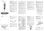
MS 300 SERIES METER USER’S MANUAL Safety Meaning of symbol CAUTION! Please consult the operating instructions before using the device. In these operating instructions, failure to follow or carry out instructions preceded by this symbol may result in personal injury or damage to the device and the installations. Meaning of symbol This appliance is protected by double insulation or reinforced insulation. It does not have to be connected to an earth protection terminal for electrical safety. Thank you for purchasing this MS304 wattmeter. To obtain the best service from your unit: - Read these operating instructions carefully, - Comply with the precautions for use. PRECAUTIONS FOR USE Never use on a voltage network over 600V with respect to the earth connection. This voltage surge category III wattmeter complies with stringent reliability and availability requirements, corresponding to fixed industrial and domestic installations (see IEC 664-1). Do not use on alternative and continuous voltages > 600V. Indoor use in environments with a maximum pollution level of 2 (EN 50419:2006) temperature of -10ºC to +50ºC and relative humidity below 90%. Respect the value and type of the fuses to avoid damaging the instrument and canceling the warranty. Fuse 1A/500V Use accessories corresponding to safety standards (EN 61010-1:2001) with 600V minimum voltage and surge category III. Before any measurement, ensure correct positioning of the leads on the wattmeter and of the switch. When the value range of a measurement is not known, place the switch at the highest caliber, and then gradually reduce it until the appropriate caliber is achieved: the reading should preferably be in the upper 2/3 of the range. The leads must be disconnected to open the lower half of the meter case Never connect to the circuit to be measured if the casing is not properly closed. 1 CONTENTS 1 DESCRIPTION..................................................................................................................................................................2 2 REFERENCE CONDITIONS ...........................................................................................................................................3 3 SPECIFICATIONS ............................................................................................................................................................3 4 MEASUREMENTS ...........................................................................................................................................................4 5 GENERAL CHARACTERISTICS....................................................................................................................................5 6 SUPPLY .............................................................................................................................................................................5 7 MAINTENANCE ..............................................................................................................................................................6 1 DESCRIPTION The MS304 wattmeter is for everyday use by electricity professionals. It offers the following functions: -Wattmeter: power measurement (DC and AC) 1-1 Safety terminals, Φ4mm COM common, terminal receiving the black lead (1) A for ADC and AAC calibers (2) COM common, terminal receiving the black lead (3) V for voltage (4) 1-2 5-range dial (5) 1 black, with anti-parallax mirror, for the PDC and PAC. 1-3 Range selection switch (6) 2 2 REFERENCE CONDITIONS Temperature: 23ºC±2ºC Humidity: 45%RH±5% Position: horizontal±2° Ensure that the pointer is at zero before starting any measurements. Zero adjustment: open the device. Mechanical zero adjustment is carried out by turning the screw on the back of the null meter. Ensure that the switch is correctly positioned. When an estimated measurement is unknown, place the switch at the highest caliber, and then gradually reduce it until the appropriate caliber is achieved: the reading should preferably be in the upper 2/3 of the range. 3 SPECIFICATIONS Connect the leads to the wattmeter (be careful of switch position, see below) and connect to the circuit to be controlled. When an estimated measurement is unknown, place the switch at the highest caliber, and then gradually reduce it until the appropriate caliber is achieved. To obtain power in W, multiply the appropriate range value by the reading coefficient indicated in the table. Range V AC/DC 60 V 120 V 240 V 480 V Range A AC/DC 0.5 A 1A 0.5 A 1A 0.5 A 1A 0.5 A 1A Power 30 W 60 W 60 W 120 W 120 W 240 W 240 W 480 W Reading coefficient 0.25 0.5 0.5 1 1 2 2 4 Internal resistance 30 kΩ 60 kΩ 60 kΩ 120 kΩ 120 kΩ 240 kΩ 240 kΩ 480 kΩ Accuracy (1) Admissible Overload (4) 1 % on AC, 2.5 % on DC 120 V (2) 240 V (3) 120 V (2) 400 V (3) 380 V (2) 600 V (3) (1) In % of end of range. (2) 2 A on the current ranges, for a maximum measurement time of 2 to 3 minutes. (3) 10 ln on current ranges, for a maximum measurement time of 5 seconds. (4) The current or voltage circuit can withstand permanent overloads of 25% 3 600 V (2) 800 V (3) 4 MEASUREMENTS 4-1 Measurement time About 2.5 seconds 4-2 Single phase measurements Place the switch on the range corresponding to the voltage and the current of the circuit on which you want to make the measurement. Connected the MS304 as shown in the diagram. Read the deflection of the needle on the measurement scale .read the value in such a way that the reflection of the needle on the anti parallax mirror is hidden. Apply the coefficient corresponding to the voltage and the current indicated by the switch. Example: 120V x 0.5A = 60W The coefficient 0.5 corresponds to the 60W on the table The result in Watts is therefore: Number of division of the reading x 0.5 4-3 Measurement of vars on 3-phase 3 wire balanced Connected the MS404 as shown in the diagram. In addition to the coefficient corresponding to the position of the switch, apply the coefficient 3 for 3-phase. See preceding example for single phase. Q (var) = 3 x number of divisions read x 0.5. 4 5 GENERAL CHARACTERISTICS 5-1 Dimensions and weight Dimensions: 165×105×50mm Weight: 670g 5-2 Maximum climatic conditions Temperature use -10ºC to +50ºC; storage -30ºC to +70ºC Relative humidity use ≤80% HR Altitude use <2000m 5-3 Compliance with international standards Electrical safety (EN 61010-1:2001) CEI 1010-1 EN61010 NF-C 42020 VDE 0411 Double insulation: Pollution level: 2 Installation category: III according to CEI 664 Allocated voltage: 600V 5-4 Electromagnetic compatibility Emission (EN 61326-1:2006) Immunity (EN 61326-1:2006) Maximum influence in the presence of conducted radio frequencies: 3 times the accuracy class if the length of the measured circuit is >3m. 6 SUPPLY To order MS304 Delivery: - 1 wattmeter - 1 user’s manual 5 7 MAINTENANCE Only use the specified spare parts for maintenance. The manufacturer shall not be held liable for any incident occurring following repairs carried out by a party other than its after-sales service or approved repairers. 7-1 Changing the fuses Opening the wattmeter: Open the device by removing the black over. Use the same type of fuses to ensure the safety of users and of the device. Fuse: 1 A/500V 7-2 Storage If the wattmeter is not used for a period of over 60 days, remove the battery and store it separately. For a shorter period, avoid leaving the wattmeter in ohmmeter position. There is a risk of premature battery wear if the tips come into contact with it. 7-3 Cleaning The wattmeter must be disconnected from all electricity sources. To clean the casing, use a cloth dampened with soapy water. Wipe over with a damp cloth. Dry quickly with a dry cloth or forced air. 6