1
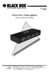
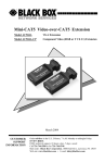
December 2001
AC154A-2
AC154A-8
Compact CAT5 Audio/Video Splitters
AC154A-2
2-Channel
AC154A-8
8-Channel
CUSTOMER
SUPPORT
INFORMATION
Order toll-free in the U.S. 24 hours, 7 A.M. Monday to midnight Friday: 877-877-BBOX
FREE technical support, 24 hours a day, 7 days a week: Call 724-746-5500 or fax 724-746-0746
Mail order: Black Box Corporation, 1000 Park Drive, Lawrence, PA 15055-1018
Web site: www.blackbox.com • E-mail: [email protected]
Compact CAT5 Audio/Video Splitter
TRADEMARKS USED IN THIS MANUAL
BLACK BOX and its logo
Corporation.
are registered trademarks of Black Box
Apple and Macintosh are registered trademarks of Apple Computer, Inc.
IBM is a registered trademark of International Business Machines
Corporation.
SGI is a registered trademark of Silicon Graphics, Inc.
Sun and Sun Microsystems are registered trademarks of Sun Microsystems,
Inc. in the United States and other countries.
Any other trademarks mentioned in this manual are acknowledged to be
the property of the trademark owners.
1
Compact CAT5 Audio/Video Splitter
FEDERAL COMMUNICATIONS COMMISSION
AND CANADIAN DEPARTMENT OF COMMUNICATIONS
RADIO FREQUENCY INTERFERENCE STATEMENTS
This equipment generates, uses, and can radiate radio frequency energy
and if not installed and used properly, that is, in strict accordance with
the manufacturer’s instructions, may cause interference to radio
communication. It has been tested and found to comply with the limits
for a Class A computing device in accordance with the specifications in
Subpart B of Part 15 of FCC rules, which are designed to provide
reasonable protection against such interference when the equipment is
operated in a commercial environment. Operation of this equipment in
a residential area is likely to cause interference, in which case the user
at his own expense will be required to take whatever measures may be
necessary to correct the interference.
Changes or modifications not expressly approved by the party
responsible for compliance could void the user’s authority to operate
the equipment.
This digital apparatus does not exceed the Class A limits for radio
noise emission from digital apparatus set out in the Radio Interference
Regulation of the Canadian Department of Communications.
Le présent appareil numérique n’émet pas de bruits radioélectriques
dépassant les limites applicables aux appareils numériques de la classe
A prescrites dans le Règlement sur le brouillage radioélectrique publié
par le ministère des Communications du Canada.
EUROPEAN UNION DECLARATION OF CONFORMITY
This product complies with the requirements of the European EMC
directive 89/336/EEC
2
Compact CAT5 Audio/Video Splitter
Normas Oficiales Mexicanas (NOM)
Electrical Safety Statement
INSTRUCCIONES DE SEGURIDAD
1. Todas las instrucciones de seguridad y operación deberán ser leídas
antes de que el aparato eléctrico sea operado.
2. Las instrucciones de seguridad y operación deberán ser guardadas para
referencia futura.
3. Todas las advertencias en el aparato eléctrico y en sus instrucciones de
operación deben ser respetadas.
4. Todas las instrucciones de operación y uso deben ser seguidas.
5. El aparato eléctrico no deberá ser usado cerca del agua—por ejemplo,
cerca de la tina de baño, lavabo, sótano mojado o cerca de una alberca,
etc.
6. El aparato eléctrico debe ser usado únicamente con carritos o pedestales
que sean recomendados por el fabricante.
7. El aparato eléctrico debe ser montado a la pared o al techo sólo como
sea recomendado por el fabricante.
8. Servicio—El usuario no debe intentar dar servicio al equipo eléctrico
más allá a lo descrito en las instrucciones de operación. Todo otro
servicio deberá ser referido a personal de servicio calificado.
9. El aparato eléctrico debe ser situado de tal manera que su posición no
interfiera su uso. La colocación del aparato eléctrico sobre una cama,
sofá, alfombra o superficie similar puede bloquea la ventilación, no se
debe colocar en libreros o gabinetes que impidan el flujo de aire por los
orificios de ventilación.
10. El equipo eléctrico deber ser situado fuera del alcance de fuentes de
calor como radiadores, registros de calor, estufas u otros aparatos
(incluyendo amplificadores) que producen calor.
3
Compact CAT5 Audio/Video Splitter
11. El aparato eléctrico deberá ser connectado a una fuente de poder sólo
del tipo descrito en el instructivo de operación, o como se indique en el
aparato.
12. Precaución debe ser tomada de tal manera que la tierra fisica y la
polarización del equipo no sea eliminada.
13. Los cables de la fuente de poder deben ser guiados de tal manera que no
sean pisados ni pellizcados por objetos colocados sobre o contra ellos,
poniendo particular atención a los contactos y receptáculos donde salen
del aparato.
14. El equipo eléctrico debe ser limpiado únicamente de acuerdo a las
recomendaciones del fabricante.
15. En caso de existir, una antena externa deberá ser localizada lejos de las
lineas de energia.
16. El cable de corriente deberá ser desconectado del cuando el equipo no
sea usado por un largo periodo de tiempo.
17. Cuidado debe ser tomado de tal manera que objectos liquidos no sean
derramados sobre la cubierta u orificios de ventilación.
18. Servicio por personal calificado deberá ser provisto cuando:
A: El cable de poder o el contacto ha sido dañado; u
B: Objectos han caído o líquido ha sido derramado dentro del aparato;
o
C: El aparato ha sido expuesto a la lluvia; o
D: El aparato parece no operar normalmente o muestra un cambio en su
desempeño; o
E: El aparato ha sido tirado o su cubierta ha sido dañada.
4
Compact CAT5 Audio/Video Splitter
Contents
1. Introduction ...............................................................................page 6
1.1 General ................................................................................page 6
1.2 Features ...............................................................................page 6
2. Installation .................................................................................page 7
3. Operation ...................................................................................page 9
4. Troubleshooting .......................................................................page 10
4.1 Problem Solving FAQ ........................................................page 10
4.2 Calling Black Box ..............................................................page 12
4.3 Shipping & Packaging ........................................................page 12
5. Specifications...........................................................................page 13
5
Compact CAT5 Audio/Video Splitter
1. Introduction
1.1 General
The Models AC154A-2 and AC154A-8 are respectively 2 and 8channel UTP (CAT5) VGA video splitters (senders) with audio. The
devices convert a PC's VGA and audio signals into a format that can be
transmitted using a single inexpensive and commonly available
Category-5 Unshielded Twisted Pair (UTP) cable with RJ45
connectors, which are used in most Local Area Networks.
At the receiving (remote) end a matching receiver (Model AC155A –
sold separately) is used to convert the UTP signal back to VGA and
audio.
The devices are housed in compact shielded enclosures and include
connectors for the local monitor and speakers as well as multiple RJ45
connectors for connection to remote monitors.
Included with the devices are: a small power adapter, and short video
and audio cables for connection to the PC’s VGA and sound card’s
outputs.
The RJ45 outputs can drive CAT5 LAN cables to 500 feet (152 meters)
with little to no degradation of video quality. A proprietary circuit in the
receiver is used to compensate for signal losses in long cable runs.
1.2 Features
6
•
Buffered video and pass-through audio outputs for connection
to local monitor and speakers
•
Support resolutions up to 1280x1024 at any refresh rate
•
Rugged, Reliable, Compact size
•
No software required
•
Drive standard CAT5 cables to 500 feet
•
Transmit audio and video signals on one cable
•
Easily expandable by daisy-chaining the local in/out ports
Compact CAT5 Audio/Video Splitter
2. Installation
1.
Connect the VGA IN and AUDIO IN connectors of the AC154A to
the computer's video and speaker ports using the supplied cables
(see figures 2.1 and 2.2).
Figure 2.1
Figure 2.2
2.
Figure 2.3
Connect the local monitor and speakers to the device's VGA OUT
and AUDIO OUT connectors respectively. (see Figure 2.3)
NOTE
To expand the number of outputs, use these ports to daisy
chain to another AC154A’s VGA and audio inputs. Connect the
local monitor and speakers to the last unit in the chain.
3.
Connect the supplied power adapter to the power input connector
on the unit.
7
Compact CAT5 Audio/Video Splitter
4.
Using Category-5 cable connect one or more AC155A receivers to
the unit's RJ45 outputs. The outputs are labeled PORT A and
PORT B on the AC154A-2 or OUT 1 through OUT 8 on
AC0154A-8.
5.
Connect the remote monitor and speakers to the receiver unit and
attach the power adapter to the receiver. Please refer to AC155A
User’s Manual for further details.
CAUTION
Before plugging in your remote monitor, verify that the AC line is
properly wired and that a protective ground (green) wire is
established with NO potential difference between both the sender
and receiver locations (The UTP splitter can tolerate up to 5 v peakto-peak ground noise between the two locations) . Failure to ensure
good grounding can result in erratic operation and possible shock
hazards with severe damage to your equipment. If an LCD is being
used at the remote location, verify that the LCD ground is tied to
power-line ground. If not, then ground the receiver unit by adding a
ground strap (see troubleshooting section for more information).
NOTICE
Do not connect this unit to any LAN device such as network cards
or hubs as this may damage the AC155A and/or the LAN device. Use
EIA/TIA 568B standard straight-through patch wiring as shown
below. Do not use crossover cables.
EIA/TIA 568B WIRING STANDARD
8
PIN
Wire Color
1
White w/ Orange Stripe
2
Orange
3
White w/Green Stripe
4
Blue
5
White w/Blue Stripe
6
Green
7
White w/Brown Stripe
8
Brown
Compact CAT5 Audio/Video Splitter
3. Operation
The video signal is fully terminated and buffered for the local video
output connector. This means that terminating or plugging a local
monitor is not necessary and this connector can be left open.
The stereo audio input is passed through to the local audio output
connector and the audio integrity is fully preserved. The transmitted
audio in the CAT5 cable to the remote receiver is monaural. The audio
outputs are “line-level” and powered speakers are required.
Assuming that there are no major grounding or large EMI noise
problems present, the video quality at the remote station depends on the
length of the CAT5 cable, actual video resolution and refresh rate.
The Model AC155A receiver employs proprietary user settable video
compensation to enhance the image quality when long cables are used.
In general at low and mid resolutions excellent image reproduction is
provided at up to 500 feet. At high resolution and refresh rates perfect
image reproduction can be achieved at shorter distances (see table 3.1
below). Using longer cables or higher resolution rates will still produce
an image, but the reproduction quality will be reduced.
Resolution
Refresh Rate
60 Hz
75 Hz
85 Hz
640x480
500 ft
500 ft
500 ft
800x600
500 ft
500 ft
400 ft
1024x768
500 ft
400 ft
350 ft
1280x1024
500 ft
350 ft
300 ft
Table 3.1
9
Compact CAT5 Audio/Video Splitter
4. Troubleshooting
4.1 Problem Solving FAQ
1.
Fuzzy, blurry, or ghosting image at remote location
If you have a stable image but it looks somewhat blurry (object or
character edges are not sharp), make sure that you have set the receiver
unit’s compensation switches correctly. Also check table 3.1 to see that
you have not exceeded the maximum cable length recommendation. If
you still have a fuzzy image, try reducing the refresh rate and/or
resolution of the PC. You can also try CAT5e or higher with improved
bandwidths (as long as the pairs are terminated as standard EIA/TIA
568B).
If too much compensation is applied at the receiver, a bright and
ghosting image may result. In this case try reducing the amount of
compensation.
2.
Image exhibits steady or rolling horizontal color “hum” bars
This is usually an indication of improper grounding either at the
sending end, the receiving end, or both. Verify that the AC line is
properly wired and that a protective ground (green) wire is established
with NO potential difference between both the sender and receiver
locations. The UTP splitter can tolerate up to 5 v peak-to-peak ground
noise between the two locations, but no more.
The splitters and receivers rely on the equipment that are connected to
them to establish a good ground reference. Most monitors and PC’s are
well grounded to the power-line through their 3-Prong AC cord.
However some Notebooks and LCD’s may be completely floating even
when an external power supply is plugged into them. In this case, you
must add a wire from the splitter or receiver to “earth” ground. The
VGA and Audio connector shells and their respective hardware are all
tied to unit’s internal ground and can be used to establish a connection
to power-line ground.
10
Compact CAT5 Audio/Video Splitter
3.
Shaking image or periodically blanking monitor
Although CAT5 cable uses twisted pairs to transmit the signals from the
splitter to the receivers to reduce the amount of EMI coupled noise
from other external sources, a strong electromagnetic noise field can
cause instability in the signal.
Usual sources of this form of noise coupling are high current AC lines
or other high-density data and/or control cables that run adjacent to and
parallel with a substantial length of the CAT5 cable. To eliminate this,
either place a distance between the CAT5 cables from the splitter and
the interfering source, or use shielded CAT5 cables. Note that
separating the CAT5 cable from the EMI source by a few inches is
often sufficient to eliminate this problem.
4.
The PC does not recognize a Plug-and-Play monitor
If the PC’s Operating System is setup to detect a plug-and-play monitor
(usually in Display Properties Advanced Settings), it may have trouble
finding a monitor if no local monitor is hooked up to the splitter. Only
the ID information of the local monitor is passed to the PC. If the PC
does not produce an image due to this, either connect a monitor to the
local VGA output port, or disable the plug-and-play monitor detection
in the PC’s operating system.
5.
Faint shadows or ghosts at the remote monitor
Your splitter has multiple RJ45 output connectors. When a long CAT5
cable is plugged in any of the outputs, the unit expects a receiver unit at
the far end for proper termination. Therefore it is a good idea to unplug
the un-terminated CAT5 cables from the splitter unit. Please refer to
item 1 above for other possible causes.
11
Compact CAT5 Audio/Video Splitter
6.
Poor audio quality at the receiving end
Only use powered speakers with the splitter and receivers. It is also
good practice to set the audio level (volume) output of the PC about 1/2
to 2/3 from the maximum and use the volume knob of the speakers to
adjust the volume to the desired level. A low volume signal output from
the PC reduces the signal-to-noise (S/N) ratio, whereas too high output
amplitude can cause saturation and clipping to occur.
7.
Substituting power supplies
The splitters rely on the AC power adapters that are supplied with them.
The adapters generate a floating 12 v DC power for the unit. If you
intend to use a different external DC power that is referenced to ground,
the splitters will not function properly.
4.2 Calling Black Box
If you determine that your splitter is malfunctioning, do not attempt to
repair the unit. Contact Black Box Tech. Support at 724-746-5500.
Before you do, make a record of the history of the problem. We will be
able to provide more efficient and accurate assistance if you have a
complete description, including:
• The nature and duration of the problem;
• The components involved in the problem—that is, what type of
cable, makes and models of computers and monitors, etc.
• The results of any testing you’ve already done.
4.3 Shipping and Packaging
If you need to transport or ship your Splitter:
• Package it carefully. We recommend that you use the original
container.
• Before you ship the unit back to Black Box for repair or return,
contact us to get a Return Authorization (RA) number.
12
Compact CAT5 Audio/Video Splitter
5. Specifications
Compliance
CE; FCC Part 15 Subpart B Class A, IC Class
Standards
VGA, SVGA, or XGA video
Interfaces
Video: VGA; CAT5: Non-Standard
Supported
Video Types
VGA through XGA, RGBS, or RGsB (sync on green”)
Resolution &
Refresh Rate Up to 1280 x 1024 non-interlaced at up to 85 Hz
Bandwidth
Video: DC to 250 MHz, Audio: 20 Hz to 10 KHz
Video Level
0.7 volts peak-to-peak
Audio
Transmission Local output: Pass-Through Stereo, Remote: Mono
Maximum
Distance
Connectors
Maximum
Altitude
Up to 500 ft. (152 meters) – See table 3.1 for details
HD15 female for video input and output
3.5 mm Mini-Stereo for audio input and output
RJ45 for CAT5 A/V outputs
10,000 ft. (3048 m)
Temperature
Tolerance
Operating: 32 to 122°F (0 to 50°C);
Storage: –40 to +185°F (–40 to +85°C)
Humidity
Up to 95% non-condensing
Enclosure
Steel
13
Compact CAT5 Audio/Video Splitter
MTBF
300,000 hours (calculated estimate)
Power
From utility-power (mains) outlet, through included
external power adapters. Output Voltage: 12v DC
Center-Positive, floating (do not substitute any other
external power supply). Power supply current
requirements: 300 ma minimum for AC154A-2, or 500
ma minimum for AC154A-8.
Size
AC154A-2 : 1.22"H x 4.86"W x 2.60"D
AC154A-8 : 1.32"H x 7.58"W x 3.88"D
(AC154-8 has 2 L-shaped mounting ears that protrude
0.88” beyond the main box on each side). 4 mounting
holes are present on a rectangular pattern of 8.62" x
2.63"
Shipping
Weight
14
AC154A-2 : 1.8 lb
AC154A-8 : 3.0 lb
NOTES
16
© Copyright 2001. Black Box Corporation. All rights reserved.
1000 Park Drive
Lawrence, PA 15055-1018
724-746-5500
Fax 724-746-0746