1
Full User Guide
Software v2.0.xxxx
satmap.com
i.
i.
ii.
iii.
1.
2.
2.1
2.2
2.3
2.4
2.5
2.6
2.7
2.8
2.9
2.10
3.
3.1
3.2
3.3
3.4
3.5
3.6
3.7
3.8
4.
4.1
4.1.1
4.1.2
4.1.3
4.1.4
4.2
4.3
4.4
4.4.1
4.4.2
4.4.3
4.4.4
4.5
4.6
Contents
Contents.............................................................2
Basic Layout.......................................................4
Map Screen Layout............................................5
Introduction...........................................6
Care for your Active 12..........................7
Safety & Care Tips:.............................................7
Battery Charging.................................................7
Spare Batteries . ................................................7
Acquiring a Lock / GPS Accuracy.......................7
Spare Mapping ..................................................7
Understanding Your Map....................................7
Extreme Weather Care Tips...............................8
In extreme weather conditions:..........................8
In the case of water submersion:.......................8
Missing/worn parts:.............................................8
Overview................................................9
Battery Power.....................................................9
Switching On, Off & Hibernate............................9
Keyboard Lock....................................................9
Map Card Insertion ............................................10
Base Mapping ...................................................10
Battery Indicator & Stop/Record Icon.................10
'PLANNING' Mode..............................................10
SatSYNC ...........................................................10
Eight Primary Screens...........................11
Primary Screen 1: GPS MAP ..........................12
GPS MAP Screen...............................................12
Toggleable Maps................................................13
Map orientation . ................................................14
Map Packs Screen.............................................15
Primary Screen 2: PLANNING.........................16
Primary Screen 3: POSITION INFO...............17
Primary Screen 4: TRIP LOG...........................18
To access TRIP LOG Screen.............................18
Convert Trail to Track.........................................19
Convert Trail to LOI/AOI.....................................19
Geotag Photos with Trip Log Data.....................19
Primary Screen 5: MAIN MENU......................20
Primary Screen 6: COMPASS/POINTER.......21
© Satmap Systems Ltd
4.6.1
4.6.2
4.7
4.8
5.
6.
6.1
6.2
6.3
6.4
6.5
6.6
6.7
6.8
6.8.1
6.8.2
6.8.3
6.8.4
6.9
6.10
6.11
6.12
6.13
6.14
6.15
6.16
6.17
6.18
6.19
6.20
6.21
6.22
6.23
7.
7.1
7.2
7.3
7.4
To access COMPASS screen.............................21
POINTER Screen...............................................22
Primary Screen 7: SHARED DATA..................23
Primary Screen 8: GPS STATUS.....................25
POWER OFF Screen...............................26
MAIN MENU: Settings Menu..................27
Access SETTINGS MENU screen......................27
Power Control . ................................................28
Advanced Power Control....................................29
Bluetooth............................................................30
Elevation.............................................................33
Backlight.............................................................35
Screen Data Capture..........................................36
Data Boxes.........................................................37
2 Data Box Layout..............................................37
4 Data Box Layout (upper).................................38
4 Data Box Layout (lower) ...............................38
Options for 2 & 4 Data Boxes.............................39
GPS Settings......................................................41
Memory Status .................................................42
Units and Set Speed .......................................43
Compass Settings .........................................44
Calibrate Compass ..........................................45
Set Trip Data.......................................................46
Volume Control ...............................................47
Button Control ................................................47
Pan and Zoom Speed ....................................48
Cycling . ..........................................................48
Screen Data Options .....................................49
Time Offset .....................................................49
Enter User Name . ..........................................49
Languages . ....................................................50
About ..............................................................50
MAIN MENU: ROUTES MENU.................51
ROUTES MENU Screen .................................51
Active and Inactive Routes ................................52
Following a Route...............................................52
Create New Route ............................................53
2
7.5
7.6
7.7
7.8
7.9
7.10
7.11
7.12
7.13
7.14
7.15
7.16
7.17
7.18
7.19
8.
9.
10.
10.1
10.2
11.
11.1
11.2
11.3
11.4
11.5
11.6
11.7
11.8
11.9
11.10
11.11
11.12
11.13
11.14
11.15
11.16
11.17
12.
Route Edit Screen ...........................................54
Edit Title . .........................................................55
Edit Comments .................................................55
Reverse Route ..................................................55
Edit Route Map . ................................................56
Edit Waypoints . .................................................56
Edit Active Route Colour ...................................57
Delete Route.......................................................57
Copy...................................................................57
Move Route to SD Card.....................................57
Copy Route to SD Card......................................57
ROUTE MAP Screen..........................................58
ROUTE PLAN Screen........................................59
ROUTE CARD Screen.......................................60
Routes Folders...................................................61
Keypad .................................................62
Choose Information Type Window........63
MAIN MENU: OOI Menu (Objects of Interest)..64
OOI Menu ..........................................................64
OOI Folders........................................................65
POIs (Points of Interest)........................66
POIs Overview....................................................66
Add POI by Map.................................................66
Add POI by Grid Reference................................67
Add POI by Postcode (UK only).........................67
Add POI in a Specific Folder..............................67
POI Details Screen.............................................67
Edit POI Menu....................................................68
Rename POI.......................................................69
Edit Description..................................................69
Edit Location by Map .........................................69
Edit Location by Grid .........................................69
Edit Warning Radius...........................................70
Edit Visibility.......................................................70
Edit POI Icon......................................................70
Delete.................................................................70
Move to SD Card................................................70
Copy to SD Card................................................70
AOIs (Areas of Interest)........................71
i.
Contents (...cont)
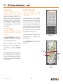
12.1 AOIs (Areas of Interest) Overview......................71
12.2 Add AOI Screen..................................................71
12.3 Add AOI in a Specific Folder..............................71
12.4 AOI Details Screen.............................................72
12.5 Edit AOI Menu....................................................73
12.6 Rename AOI.......................................................74
12.7 Edit Description..................................................74
12.8 Edit Location by Map .........................................74
12.9 Edit Visibility.......................................................74
12.10 Edit Colour..........................................................75
12.11 Edit Pattern . ......................................................75
12.12 Delete.................................................................75
12.13 Move to SD Card................................................75
12.14 Copy to SD Card................................................75
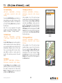
13. LOIs (Lines of Interest).........................76
13.1 LOIs (Lines of Interest) Overview.......................76
13.02 Add LOI Screen..................................................76
13.03 Add LOI in a Specific Folder...............................76
13.4 LOI Details Screen.............................................77
13.5 Edit LOI Menu.....................................................78
13.6 Rename LOI.......................................................79
13.7 Edit Description..................................................79
13.8 Edit Location by Map .........................................79
13.9 Edit Visibility.......................................................80
13.10 Edit Colour..........................................................80
13.11 Delete.................................................................80
13.12 Move to SD Card................................................80
13.13 Copy to SD Card................................................80
14. Grids.......................................................81
14.1 Grids Overview...................................................81
14.2 Add Grid Screen.................................................81
14.3 Add Grid in a Specific Folder..............................82
14.4 Grid Details Screen............................................82
14.5 Edit Grid Menu....................................................83
14.6 Rename Grid......................................................84
14.7 Copy...................................................................84
14.8 Delete.................................................................84
14.9 Move to SD Card................................................84
14.10 Copy to SD Card................................................84
© Satmap Systems Ltd
14.11 Edit AOIs Within a Grid.......................................85
15. IOIs (Items of Interest)..........................86
15.1 IOIs (Items of Interest) Overview........................86
15.2 Add an IOI..........................................................86
15.3 Add IOI in a Specific Folder................................86
15.4 IOI Details Screen..............................................86
15.5 Edit IOI Screen...................................................87
15.6 Rename IOI........................................................88
15.7 Edit Description..................................................88
15.8 Delete.................................................................88
15.9 Move to SD Card................................................88
15.10 Copy to SD Card................................................88
16. MAIN MENU : GoTo and Marker............89
16.1 GoTo and Marker Overview................................89
16.2 GoTo & Marker – Set By Coords .......................89
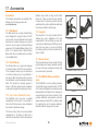
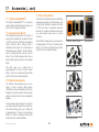
17. Accessories...........................................90
17.1 Bike Mount. .......................................................90
17.2 Vehicle Mount. ...................................................90
17.3 Carry Cases (Standard & Deluxe)......................90
17.4 Lanyard...............................................................90
17.5 Screen Cover. . ..................................................90
17.6 ProSHIELD (Silicon protective case)..................90
17.7 ZAGG invisibleSHIELDTM.................................91
17.9 Standard Power Bundle.....................................91
17.10 Slimline Power Bundle ......................................91
17.11 Solar Power Bundle . .........................................91
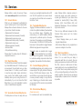
18. Services.................................................92
18.1 General Service..................................................92
18.2 World Base Map.................................................92
18.3 Specialized Custom Map Service.......................92
18.4 Toggleable Map Service.....................................92
18.5 Custom Mapping (GB only)................................92
18.6 Site-Centreed Mapping .....................................92
18.7 Map Consolidation..............................................92
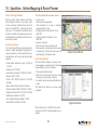
19. Xpedition : Online Mapping & Route Planner.....93
20. Tips........................................................94
21. Troubleshooting . ...............................................95
22. Glossary.............................................................96
3
Bluetooth Icon
Stats Recording
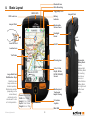
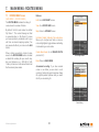
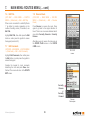
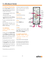
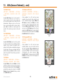
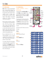
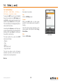
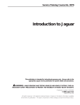
ii. Basic Layout
Toggle Map Icon
SiRF III GPS
GPS Lock Icon
Battery
Indicator
Lanyard Point
Lanyard Point
Replaceable
Screen Cover
Backlight
Boost
Insert SD Card
Lock/
Unlock
On/Off
Location Icon
Trail Taken
Planning Icon
3.5 in / 8.7cm
Bright, Hi-Res
HVGA (320x480)
Screen
Large Side/Front
Multifunction Keys
Side/front press
keys enable onehanded operation.
Buttons are variable
(depending on the
screen shown)
and can be set to
activate with 1-click
or 2-click operation .
© Satmap Systems Ltd
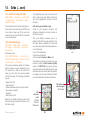
Weatherproof,
Toughened
Impact Casing
Screen 3.4 in / 8.7cm
Width 3 in / 7.5cm
Height 5.1 in / 13cm
Depth 1.4 in / 3.5cm
Weight 6.2 oz / 175g
Removable
Battery Back
Can be
replaced with
a Battery Back
for mounting
on a bike or
in a car, or
with a Slimline
Battery Back
for a lighter unit
with a lower
profile.
9 Function
Joystick
Mini USB
4
© Satmap Systems Ltd 2014
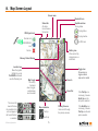
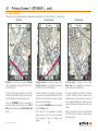
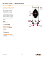
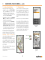
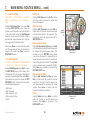
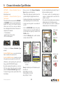
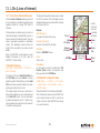
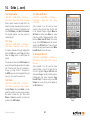
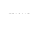
iii. Map Screen Layout
Screen name
Bluetooth Icon
GPS Signal Lock
Stop/Record Icon
Trip log status
Status Bar
All status
icons shown in
the top bar
Trip Log Active
Trip Log Inactive
Normal lock
No GPS Lock
EGNOS/WAAS
lock
No lock
Battery icon
When unit is fully
charged icon is a
solid block
Memory Status Warning
Location Icon
Move the joystick
left/right to go into
PLANNING mode and
see the Planning icon
The icon on the
lower left shows
the orientation that
will next appear if
the front left button
is selected.
© Satmap Systems Ltd
Zoom In
Map Toggle
This is only
functional
when a toggleenabled map
card is loaded
Zoom Out
Map orientation
Trail Up
North Up
5
Primary Screens
Use to scroll through
the primary screens
Toggle Icon
Shows when a
toggle-enabled
map card is loaded
If the Trail Up icon
is showing, it means
North Up was the
last option selected.
If the North Up icon
is showing, it means
Trail Up was the last
option selected.
© Satmap Systems Ltd 2014
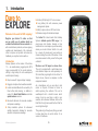
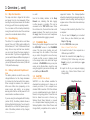
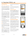
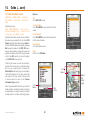
1. Introduction
Dare to
EXPLORE
Hi-Res (HVGA) bright 3.5" colour screen
Welcome to the world of GPS mapping!
Extensive range of international maps
Long battery life with numerous power
management options.
Ability to plan routes on GPS and online
Introduction
The Active 12 is latest model from Satmap
Systems ultimate sports GPS range. It is
easy-to-use and intuitive, showing a blue
location dot on a real map so you know exactly
where you are at all times. Switch it on, wait
for a couple of minutes and your position is
shown as being the centre of the screen. It has
never been easier to find yourself in the great
outdoors!
Easy-to-use with ‘plug-and-play’ mapping
We have over 350 maps to choose from.
The unit is supplied with a world base map,
and individual maps are sold separately on
SD cards that plug straight into the Active 12.
Simple to use, there is no computer or other
equipment needed.
Register your Active 12 online so that
we can notify you of updates which are
available for download from our website. As
with most software products, we have ongoing
updates and developments. We continually
strive to improve our product and value any
feedback you may like to share with us.
Satmap Systems is the creator of the Active
12 — an award-winning rugged sports GPS
range, purpose-built for the great outdoors,
offering a long battery life in a weatherproof
and shockproof casing.
Rugged, shockproof and weather-resistant
Latest dual-band Bluetooth connectivity for
Peer-to-Peer data sharing, in addition to
support for Heart Rate Monitors and bike
speed/cadence sensors.
Barometric altimeter for accurate elevation
and pressure readings.
Map orientation options for enhanced
visibility barometric altimeter for accurate
elevation and pressure readings.
© Satmap Systems Ltd
As a standalone unit, you are able to plot
routes or Objects of Interest at home or
whilst exploring the outdoors. The unit is
weatherproof with a backlit screen which
means it can be used day or night in any
weather, with enhanced features such as the
Red Filter for night vision and the Sun Filter for
use in bright sunlight.
This guide will go through everything you need
to know about how to use the Active 12 on
version 2.0 software.
6
© Satmap Systems Ltd 2014
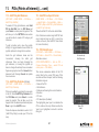
2. Care for your Active 12
2.1
Safety & Care Tips:
The Active 12 is purpose-built for the great outdoors, offering a long battery life in a weatherproof and shockproof casing. Although the
unit has been built to be rugged and reliable,
you should remember that this is a complex
electronic device requiring specific care and
maintenance.
These tips are intended to provide you with
suggestions on getting the most from your
Active 12, ensuring you have many years of
accurate and reliable GPS and digital map use.
2.2
Battery Charging
2.3
Spare Batteries
When using the Lithium Polymer battery option
supplied by Satmap, it is extremely important
that you only use Satmap products to charge
the battery (i.e. Satmap Wall Charger, Car
Charger, etc.) Failure to do so is potentially
dangerous, may damage the Active 12, or
result in partial or complete loss of warranty.
We recommend that you always carry a set
of new / spare batteries, and keep them in a
watertight wrapping. Although the Active 12
will give you many hours of use, it can be
difficult to keep track of the length of time you
have been using the batteries, so it is always
good to have a back up.
© Satmap Systems Ltd
2.4
Acquiring a Lock / GPS Accuracy
To acquire a satellite lock, the Active 12 should
be under open skies, immobile and held
upright. When a lock has been acquired, the
top left signal icon will change from a red ‘x’
to green or blue crescents, depending on the
signal. (Satellite lock times vary).
It is important to remember that the accuracy
of any GPS is variable. The GPS system uses
triangulation on a constellation of satellites
circling the earth to determine a position on
the ground. There are a number of factors
which can reduce the accuracy of this position
information, including poor weather, a limited
view of the sky (e.g. in a building, urban/natural
canyons, under a thick tree canopy, etc),
metallized glass (such as a car windshield), etc.
You may also notice a variable performance
from one day to the next. This is due to the
fact that the position of the satellites relative to
the ground can change, resulting is a different
triangulation value.
2.5
Spare Mapping
2.6
Understanding Your Map
Although the Active 12 has been designed for
use in the great outdoors, carrying a paper
map of the area and a compass is always
considered good practice.
Although the Active 12 gives your exact
position on a map, it is important that you
understand the symbols and notations on the
map. If you are unsure about these, you can
download them from our website:
www.satmap.com
Understanding this variability in the accuracy
is important when enjoying outdoor sports in
the proximity of dangerous features (e.g. cliffs,
marsh, rivers, lakes, etc.) as users must still
apply safe practice, be aware of the weather
conditions and their own abilities in order to
avoid unnecessary risks and dangers.
7
© Satmap Systems Ltd 2014
2.
2.7
Care for your Active 12 (... cont)
Extreme Weather Care Tips
It is important to remember that the Active 12
unit is weatherproof (not 100% waterproof),
which means it can withstand weather
conditions such as rain and snow, but is not
submergible in water. Rated at IP65, the Active
12 will have no harmful effects from rain and
is also dust tight, providing the rubber doors
are closed.
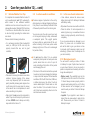
2.8
1
• It is extremely important that all watertight
seals (i.e. USB port & SD card slot) are
properly closed after use, and in good
condition.
2
• Map cards: Do not expose the mapcards to
water. They should be kept dry and clean at
all times. NEVER insert a damp, wet or dirty
map card into the Active 12.
© Satmap Systems Ltd
Provide a degree of protection to the unit by
either placing in a Satmap Standard or Deluxe
Carry Case, or use a Satmap ProShield. Either
of these will protect the unit from driving rain.
You can also carry the unit around your neck
on the lanyard, keeping it safely underneath
a waterproof jacket. This upright position
will ensure that any water slides off the unit,
without collecting at the base (where water
damage might occur if the unit is submerged
for periods of time).
Please note the following instructions:
SD card door
USB door
• Take care if removing the screen cover while
outdoors. Vigorous tugging of the screen
cover may temporarily pull the main seal
apart, potentially allowing water ingress. Use
a soft damp cloth to wipe down the screen
in the case of rain or mud splashes, to avoid
undue scratching to the plastic.
In extreme weather conditions:
• Do not keep the Active 12 in an external
waterproof jacket pocket or back pack outer
pocket, where there is a risk of a pool of
water collecting at the bottom of the pocket
and damaging the unit.
• The interior of the unit should not be exposed
to water or dust. Avoid changing the batteries
or map card whilst exposed to bad weather
conditions. With the SD Card door, USB door,
or battery back open, the Active 12 will not
remain weatherproof. Should water or dust
enter the Active 12, do not switch it back on
until it has been completely dried out or the
dust has been removed.
8
2.9
In the case of water submersion:
• Once indoors, remove the screen cover,
battery back and LiPol battery/AA batteries
with battery caddy.
• Wipe down the screen cover with a soft cloth.
• Place the Active 12 and components in a
warm, dry place (e.g. on a window sill near a
heater or airing cupboard), and let them dry
completely.
If you are unsure about any damage to your
Active 12, please call our technical team
who will be able to give you advice on how
to proceed, and if necessary, repair your unit
accordingly. (Please refer to satmap.com for
your local number).
2.10 Missing/worn parts:
You will need to send your Active 12 back
to Satmap for repair if parts have been lost
or worn down. Failure to do so may result in
partial or complete loss of warranty, as it will no
longer be weatherproof.
• Rubber seals: The watertight seal on the
USB port and the SD card slot of the Active
12 should always remain properly intact to
prevent water leaking into the unit. If either
of these seals is lost or damaged, you will
need to send your Active 12 back to Satmap
for repair.
• Joystick: If your joystick is worn down or
ripped, this can cause water to leak into the
unit. Please send your Active 12 back to
Satmap for repair.
© Satmap Systems Ltd 2014
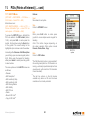
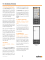
3. Overview
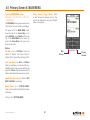
3.1
Battery Power
The Active 12 can be powered by a Lithium
Polymer rechargeable battery, or three
AA batteries. The rechargeable battery is
optimized to last longer over a wide range of
temperatures/conditions and lasts significantly
longer than AA's. Since AA batteries vary
significantly in power and life from one type
to another, we recommend using Lithium
Energizers which are the most powerful on
the market. It is not advisable to use cheap
batteries in the unit as they will have a short
life.
There are 4 ways to conserve power:
1. Select a ‘Screen Turn Off’ option
Settings > Power Control > Automatic Screen
Turn Off > Select ‘Off after 3 minutes’
2. Change the Power Saving Mode to
Advanced, so the GPS MAP screen updates
every 4 seconds instead of every second.
Settings > Advanced Power Control > Power
Saving Mode > Advanced
Note: The "Trail Up" facility is disabled when in
Advanced Powersaving Mode, and backlight is
limited to 80%.
3. Decrease the Backlight setting
Settings > Backlight (adjust slider accordingly)
4. Use Hibernate Mode to set an ultra low
power state and rapid satellite acquisition.
Power Button > Hibernate for X hours
3.2
Switching On, Off & Hibernate
When first installed, the software allows users
to select the operating language. Whatever
language is selected, the unit is then set for
the appropriate GPS position: i.e. selecting
English sets up the GPS default to Great
Britain.
After switching on the unit, the GPS STATUS
screen will load up. The bars at the bottom of
the screen indicate how many satellites are in
range of the Active 12.
Keyboard Lock
The Power Off? screen has a padlock (Keypad
Lock) icon by the On/Off button. Press the On/
Off button to lock the keypad. A padlock icon is
displayed by the battery indicator.
To unlock the keypad press any button and the
Unlock screen will be displayed. Select Yes to
unlock the keypad. If no selection is made after
3 seconds the unit will revert to the previous
screen.
When the bars turn from yellow to orange this
shows that the unit has locked to that specific
satellite. In general, the unit needs a minimum
of four satellites to get a lock. Outdoors, the
unit should get a lock within three minutes. If
it takes much longer, please contact Satmap.
Hibernate mode allows rapid satellite lock as
the unit remembers the satellites’ position.
On / Off /
Lock
Button
To switch the unit off, press the On/Off button
and a Power Off? screen is displayed in order
to prevent accidental switch-off; select Power
Off. Your data will be saved before power off. If
no selection is made after 10 seconds the unit
will revert to the previous screen.
Hibernate mode puts the unit into a very
low power state, but keeps the real-time clock
alive. This permits a very quick boot-up time
& fast satellite lock when the power button is
re-pressed.
Note: Trip log data is not stored in this mode.
© Satmap Systems Ltd
3.3
9
Keyboard
Lock
Power Off screen for
Hibernate options
© Satmap Systems Ltd 2014
3. Overview (... cont)
3.4
Map Card Insertion
The map card door is hinged at the bottom
and opens from the top downwards. When
inserting the card please ensure that the label
is facing you with the arrow pointing inwards.
You can make an SD card write-protected by
moving the switch on the side of the card down
(saves from accidental deletion of files).
3.5
Base Mapping
The Active 12 is supplied with a world base
map at 1:5m up to 1:200m (and in addition for
UK customers, a 1:1 m & 1:250k scale UK road
map). Once a map card has been inserted,
you can zoom through the base mapping to
see more detail. If you have a toggleable map,
you can switch between different map layers at
a particular point on the same zoom level, e.g.
you can flip between the two scales (1:50k and
1:25k) and the base map.
3.6 Battery Indicator & Stop/Record
Icon
The battery indicator is solid for new or fully
charged batteries. As the charge decreases
it is broken into four bars which then reduce.
When a single bar remains, it is coded red.
After some further time (depending on the
power source and activity), an on-screen
warning alerts that the unit will power off in 30
seconds and a countdown is shown.
If you are using the rechargeable LiPol battery
(section 20.03), the battery indicator shows a
lightning flash whilst charging. You will need to
disconnect the unit from the power supply to
check if the battery indicator is fully charged,
© Satmap Systems Ltd
i.e. solid.
Next to the battery indicator is the Stop/
Record icon, indicating that data logging
is either paused or recording. This can be
accessed on the TRIP LOG screen. When
the unit has a lock, the record icon has a solid
green arrowhead. The record icon is shown
as ‘empty’ when there is no lock. A red pause
symbol indicates data logging is paused.
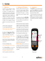
3.7
'PLANNING' Mode
Moving the joystick changes the screen from
the GPS MAP screen to the PLANNING
screen. The blue circle (location icon) will
move away from the middle of the screen
as you control the joystick to move the map.
A visual cue that you are in planning mode
is the orange locator circle which has longer
crosshairs. In PLANNING mode you can plan
routes via the Routes Menu, study the map
using the joystick to pan across the map, and
set a GoTo point/Marker/POI.
3.8
SatSYNC
(Refer to SatSYNC User Guide)
SatSYNC is a free software available for
download from satmap.com. It allows you to
connect your Active 12 to a computer via a
standard USB connection. With this software
you can upload/download routes, Objects of
Interest, and geotag photos. These files can
then be shared via e-mail or forums (e.g.
Satmap Route Share Network) or viewed
on a computer-based mapping system (e.g.
Satmap-Xpedition Online Route Planner and
Google Earth), compatible with a number of
10
supported formats. The Satmap-Xpediton
allows the download of pre-planned routes, the
upload of routes for editing, and the printing of
a paper version of the route to take as back-up
when outdoors.
To view your trail recorded by the Active 12 on
a computer:
1. You will need to Export your converted
track. Once you have finished your walk,
Stop the Trip Log.
2. On the TRIP LOG screen press
Menu > Convert Trail to Track
3. Connect the Active 12 to a computer via a
USB and open SatSYNC.
4. Select the converted track (.map file, e.g.
2010-06-24_1502 167km.map) and press
Export to copy to your desktop as a .gpx
or .kmz file.
5. Import the file to your computer mapping
system (e.g. Online Route Planner and
Google Earth).
Stop/Record Icon
Battery
Indicator
Insert
SD Card
Map
Toggle
Icon
© Satmap Systems Ltd 2014
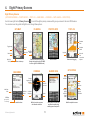
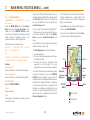
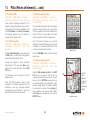
4. Eight Primary Screens
Eight Primary Screens
(GPS MAP/PLANNING → POSITION INFO → TRIP LOG → MAIN MENU → COMPASS → DATA SHARE → GPS STATUS)
Use the lower right button (Primary Screens
) to scroll through the primary screens which give you access to the main GPS features.
You can also move the joystick left/right to scroll through these options.
GPS MAP
POSITION INFO
PLANNING
TRIP LOG
Elevation
data
Toggle maps
Zoom In
Data boxes
North Up/
Trail Up
Your position on the map
Add/View
Routes
Access to main functions
© Satmap Systems Ltd
Calibrate
Compass
Extra functions
Menu for
trail
conversion
options
Data and trail logging
GPS STATUS
SHARED DATA
COMPASS
Orange
tipped north
indicator
Add/View
OOIs
Log data
Pan and zoom across the map.
(Nudge the joystick on the GPS MAP
screen to get to PLANNING mode).
MAIN MENU
GPS Map
(your position
on the map)
Elevation
profile
ROUTES
Zoom Out
MENU
Signal
indicator
Bearing
indication
given here
Satellites’
atomic
clock time
Average
Signal
to Noise
Ratio
(SNR)
Pointer
Nearby Active 12 units that
may have shareable data,
showing name & unique ID.
Built-in electronic compass
with direction indicator
11
Maximum
Signal to
Noise Ratio
Satellite acquisition screen
© Satmap Systems Ltd 2014
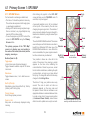
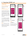
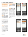
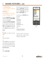
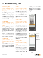
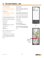
4.1 Primary Screen 1: GPS MAP
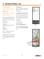
4.1.1 GPS MAP Screen
For best results in achieving a satellite lock;
• The Active 12 should be pointed at clear sky.
The unit can also acquire a lock through glass,
i.e. windows/car windshield.
• Getting a GPS whilst moving may take longer.
From a cold start, very large MapCard may
slow the GPS lock time slightly.
• To see the progress og the GPS lock set the
screen to GPS STATUS using the Primary
Screens button.
The primary purpose of the "GPS Map"
screen is to display your own location in
the centre of the screen (blue circle) and the
mapping around you.
Buttons (from L to R):
Toggle maps
(Icon is three layers of stacked mapping)
Toggle between available maps at the same
zoom level.
Data boxes
Toggle between none, 2 or 4 data boxes onscreen
North Up/Trail Up
Map display cycles through North Up, Trail Up
(Centre), and Trail Up (Low)
Primary Screens
Scroll through primary screens
Zoom In / Out
Map scale is continuously displayed during
zooming
© Satmap Systems Ltd
Note: Moving the joystick in the GPS MAP
screen will take you into PLANNING mode. To
avoid this, lock your keypad.
A successful satellite lock (a ‘fix’) is indicated
at the top left of the screen by the red cross
changing to a green signal icon. The number of
green crescents denotes the signal strength. A
weak lock is indicated by a single crescent plus
a ‘2D’ caption.
Toggle
icon
Snail Trail
Toggle
maps
The unit is EGNOS/WAAS enabled. This means
users in Europe and North America are able to
benefit from ‘differential’ GPS when one of the Data box
EGNOS/WAAS satellites is in view. When this
GPS MAP
service is available, the green signal crescents
screen with
North Up/
turn blue and accuracy is enhanced.
function buttons
Trail Up
Your position is shown as a blue dot in the
centre of the screen. Once moving, a pointer
appears on the blue circle, indicating the
current direction of travel. As you move, a snail
trail of red dots is laid down, indicating the path
you have taken, as long as you have started
the trip log. To change the red trail dot size may
Blue
changed in the Settings Menu.
pointer
The Active 12 logs your position once every
second. The rate at which red dots are
displayed depends on the map scale and
the speed of travel. Dots are laid down so an
appropriate distance is rendered between them
to create a clear track. A power saving option
(in Advanced Power Control), allows screen
Blue pointer appears once you start
data to be set to update once every 4 seconds.
moving to indicate direction of travel.
12
Zoom
In
Zoom
Out
Primary
Screens
© Satmap Systems Ltd 2014
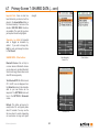
4.1 Primary Screen 1: GPS MAP (...Cont)
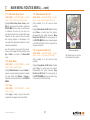
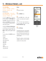
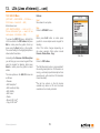
4.1.2 Toggleable Maps
Map toggling is a feature available on all
Active 12's. Toggle-enabled MapCards allow
you to switch between different map layers at
a particular point on the same zoom level. For
example, you can flip between the two scales
(1:50k and 1:25k) and the Base Map. It is also
possible to toggle between different map types
and map providers.
If a toggle-enabled MapCard is loaded, a
mini toggle symbol
appears next to the
Stop/Record icon on the GPS screen in the
status bar, indicating the map inserted can be
toggled. This enables the toggle maps button
on the left.
Note: Not all maps are toggleable. Look for the
toggle icon or logo on all of our toggle-enabled
products. The toggle function can also be
added to existing map cards (see satmap.com
for further details on this service).
Toggle icon
Toggle Symbol
(shown on screen)
© Satmap Systems Ltd
Toggle logo
Toggle
icon
Getting Started:
• Insert your SD card. This will load your Map
Packs screen.
• Use the joystick to flip between maps, and
select View Map to access the desired GPS
MAP screen.
• To access the Map Packs screen at any point,
centre press the joystick (or page forward on
the Primary Screens to POSITION INFO)
and select Map Packs using the lower lefthand side button.
Toggle between maps by pressing the upper
left-hand side button (Toggle maps) and
switch seamlessly between different maps
without having to zoom in or out.
Toggle
maps
OS 1:25 000
scale mapping
Please note: Most detailed maps have a
"ceiling", and will disappear from the screen
when zoomed out above this ceiling. This is
intentional, as the map detail would be too
small to observe clearly. If no other maps
are available for toggling, the Toggle icon will
disappear.
Toggle maps button appears bold when
suitable map card is loaded and map
areas and zoom levels overlap.
Toggle maps button appears gray when
toggle function is not available.
13
OS 1:50 000
scale mapping
© Satmap Systems Ltd 2014
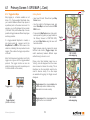
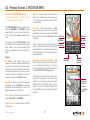
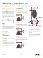
4.1 Primary Screen 1: GPS MAP (... cont)
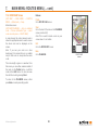
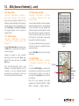
4.1.3 Map orientation
There are 3 map orientation options for enhanced visibility: North Up / Trail Up (Centre) / Trail Up (Low)
North Up
Trail Up (Centre)
Trail Up (Low)
North Up is currently on the screen. Trail Up
can be selected by pressing the Trail Up icon
(front left button).
Trail Up (Centre) is currently on the screen.
Trail Up (Low) can be selected by pressing
the Trail Up icon (front left button).
Trail Up (Low) is currently on the screen.
North Up can be selected by pressing the
North Up icon (front left button).
The blue location icon is shown in the centre
of the screen with North facing up on the map.
Use this mode to conserve battery power.
The blue location icon is shown in the centre
of the screen. The map orientates to match the
direction of travel (similar to turning a paper
map to find your bearings).
The map orientates to match the direction
of travel. However the blue location icon is
positioned low on the screen so you can see
more mapping ahead of you. Useful for when
you are traveling at higher speeds, such as on
a bike.
From the PLANNING screen if you wish to
switch the map to North Up, return to the GPS
Map screen and press the North Up/Trail Up
button.
© Satmap Systems Ltd
If you switch to PLANNING mode, the map will
stay in Trail Up mode.
Note: Trail Up is not available in advanced
power saving mode. (The screen refreshes
more frequently in Trail Up, drawing more
power).
14
Note: The 4 data box option is not available in
the Trail Up (Low) mode as it would obscure
the locator circle.
© Satmap Systems Ltd 2014
4.1 Primary Screen 1: GPS MAP (...cont)
4.1.4 Map Packs Screen
(GPS MAP → POSITION INFO via centre
press → Map Packs), or Page Forward.
(Available once a map card is inserted).
Map
title
Map
title
Alternative access:
(PLANNING → POSITION INFO via centre
press → Map Packs), or Page Forward.
A map card may be inserted or removed at any
time. When a map card is inserted, the unit
beeps three times, and an on-screen message
shows, ‘SD Card Inserted’. After a short time,
(depending on the size of the map), the Map
Packs screen appears (map title screen). After
about ten seconds the screen will revert to the
previous screen.
If you have multiple layers on your MapCard
(e.g. you may also have consolidated more
than one map on a MapCard (a service offered
by Satmap), you can access the different maps
by moving the joystick left/right on the Map
Packs screen.
ProTip: The detailed name of the Map /
Layer can be seen in the box at the top of the
MapPacks screen. You'll note in the Figures to
the right, whilst the images look similar - the
scale detail in the top box differs.
© Satmap Systems Ltd
Buttons:
Back
Return to POSITION INFO
View Map
Go to PLANNING screen
Map
title
Note: The screen shows a default location
for the loaded map, generally a notable
point or the centre of the map area.
15
© Satmap Systems Ltd 2014
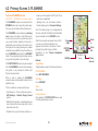
4.2 Primary Screen 2: PLANNING
To access PLANNING screen
(GPS MAP → Planning, via joystick nudge)
The PLANNING screen is accessed from the
GPS MAP screen by moving the joystick away
from your current location (blue location icon).
The PLANNING screen displays a planning
icon (orange circle with a small black cross)
as soon as you move the joystick away from
your current location. Instead of a blue dot, a
small black cross is shown in the centre. From
the edges of the orange planning icon radiate
crosshairs as an additional visual cue that you
are in PLANNING mode rather than GPS MAP
mode. The orange planning icon stays in place
as you use the joystick to move the map.
The POSITION INFO screen may be accessed
from the PLANNING screen by centre pressing
the joystick, or by pressing the bottom right
Primary Screens button.
When a map is loaded, the PLANNING
screen shows a central default location for that
particular map.
There is a data box overlay which shows;
• Grid reference – format options are given in
GPS Settings / Position Display Format
option).
• Altitude for this location – elevation above sea
level, obtained from base maps (UK) or from
map cards (non-UK).
where you last acquired a GPS lock. This is
useful as a ‘rangefinder’.
• Bearing from your last known location –
format options given in Compass Settings.
Note: This data overlay is not configurable by
the user, unlike the 2-Data Box and 4-Data Box
layouts available on the GPS MAP screen.
When the crosshairs are moved over an OOI
or a route, an OOI/route indicator icon
appears at the bottom of the screen. Centre
pressing the joystick brings up further
information via the 'Choose Information
Type' window.
Buttons:
Toggle Maps
Toggle between maps at the same zoom level
Toggle
maps
Zoom
In
ROUTES
MENU
Zoom
Out
GPS Map
PLANNING
Screen
Primary
Screens
ROUTES MENU
Go to ROUTES MENU
GPS Map
Go to GPS MAP
Zoom
Zoom in/out
Primary Screens
Page forward to POSITION INFO screen and
scroll through primary screens
• Distance from your last known location, i.e.
© Satmap Systems Ltd
16
© Satmap Systems Ltd 2014
4.3 Primary Screen 3: POSITION INFO
To access POSITION INFO Screen:
Add POI - Will place a POI menu at the centre
of the circle. A defult name will be given (e.g.
POI 1) that can be over written, and a POI Icon
can be selected.
The POSITION INFO screen is accessed from
either the GPS MAP or PLANNING screens
screen either by a centre press of the joystick,
or by pressing the Primary Screen button
once.
Set GoTo - This function places a GoTo
waypoint at the centre of the circle. A solid blue
line will then connect your location to the GoTo
point at all times, until the Clear GoTo button Local Grid
is pressed.
Set Marker
This is a particularly useful and quick way of Map Packs
setting a simple, single-leg route. Especially
when zoomed in to view map detail, and when
in Track Up mode, the GoTo line still shows the
required direction.
(GPS MAP / PLANNING → POSITION INFO,
via Primary Screen page forward)
The purpose of the POSITION INFO screen
is to display useful information about that particualr location, be it your own location (GPS
MAP) or somewhere else on the map (PLANNING).
Buttons:
Set Marker - This function allows you to
measure the distance and bearing between any
two points on the map, the first point being the
centre of the circle in the middle of the screen,
and the second point being any that you cursor
to with the joystick, connected by a red line.
Cleared by using the Clear Marker button.
Map Packs - Allows you to see the maps that
are present on your SD MapCard. A separate
BookCover will be displayed for each of the
MapPacks present on the SD card.
Info Boxes: Local Grid & Lat/Long - This
features allows the location of the circle centre
to be simultaneously displayed in two grid
formats. The format of Local Grid is determined
in the SETTINGS / GPS Settings screen.
The format of the right hand box has be preset as Lat/Long (decimals). This feature is very
useful if you may need to quickly convert one
position format into another: simply use the
joystick to cursor to the desired location, and
then read off the other format version of the grid
reference.
GPS Map
Lat/Long
Set GoTo
Add POI
Primary
Screens
Alternate
access if
cursor is
on a Route
or POI
Maps - Flicks you back into your previous map
screen (GPS MAP or PLANNING).
Primary Screens - Pages forward to the TRIP
LOG screen.
© Satmap Systems Ltd
17
© Satmap Systems Ltd 2014
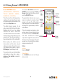
4.4 Primary Screen 4: Trip Log
4.4.1 To access TRIP LOG Screen
(GPS MAP→ POSITION INFO→ TRIP LOG),
(PLANNING→ POSITION INFO→ TRIP LOG)
The upper half of the TRIP LOG screen is split
into 12 data fields:
• Total distance travelled (Total Dist)
• Total time (Total Time)
• Time of last reset (Trip Reset)
• Straight line distance: from start position to
end position (Strt Line Dist)
• Time moving (Time Moving)
• Average moving speed (Av Moving)
• Speed now (Speed Now)
• Average speed (Av Speed)
• Maximum speed (Max Speed)
• Sunrise time (Sunrise)
• Sunset time (Sunset)
• Altitude above sea level (Elevation)
All units can be given in metric or imperial.
The lower half of the TRIP LOG screen shows
a graph of the elevation profile of your journey.
Above the graph, a red pointer indicates the
maximum height and a blue pointer indicates
the minimum height. Figures for these heights
are given below the graph. Also shown is the
abbreviation ‘Asc:’ for ascended height.
Buttons:
Start/Stop
Press to start/stop data logging.
(Note: remember that if Stop is showing, it
means Start was the button pressed previously
and the GPS is logging data).
The unit’s data logging functions are intended
© Satmap Systems Ltd
to register a single trip. The log should be reset
before starting the next trip. Using the Start/
Stop button allows you to pause data logging
during a journey, e.g. pausing for a lunch break.
When Stop has been pressed, the unit stops
all data logging. If you switch to the GPS MAP
screen and continue moving, no new snail trail
is created.
a straight line snail trail to your present location
and will be incorporated into subsequent data
logging.
Elevation data data is obtained from maps,
GPS, or derived from Pressure data. See GPS
Settings for more details (section 7.09).
Spot Button (GPS Map)
Return to GPS MAP
Primary Screens (Page Forward)
Go to GPS STATUS screen and scroll through
primary screens.
Trip Log Status:
(Stop/Record Icon)
Trip Log Active
Trip Log Inactive
Menu
Access the following range of options:
• Reset All
• Reset All & Convert
• Reset Log (keeps the snail trail and elevation
profile)
• Reset Trail (also resets elevation data)
• Reset Trail & Convert
• Convert Trail to Track
• Set Trip Data
Elevation
profile
Stop
There are on-screen descriptors for each option.
If you would like to save your data before Trip Log
resetting, choose one of the ‘Convert’ options in has started
the menu.
As the trip log data uses up memory on your
unit, make sure you reset the trip log regularly to
maintain optimum performance.
Note: If you transit between trips and press Start
without resetting the log, the transit is shown as
18
Elevation
data
GPS Map
Access
Menu
options
TRIP LOG
screen
Primary
Screens
Note: Trip log data is not stored in hibernate
mode.
© Satmap Systems Ltd 2014
4.4 Primary Screen 4 : TRIP LOG (... cont)
4.4.2 Convert Trail to Track
than a pre-planned route, and consequently the files
will be larger.
When a route has been completed the (snail)
trail can be saved for reference, future use, or
for swapping with others on the Route Share
Network. Select the Convert Trail to Track
option to convert the snail trail of red dots into
a track.
Note: At the bottom of the elevation profile screen
there is a list of all the trip data attached to each
waypoint on the route.
(TRIP LOG → Menu → Convert Trail to Track)
Waypoints will automatically be added at key
points on the map. As these are computer
generated, the positions should be checked and
where appropriate, amended to ensure they are
practical from a user’s point of view. When the
track has been created, this can be viewed on
the unit in the Routes Menu, or can be shared
using the SatSYNC program (free download
from www.satmap.com).
The terms trail, route and track are used to
describe different stages of a recorded route:
Trail: The path that has been taken, shown as a
series of red dots (‘snail trail’).
Route: The planned path users intend to take. It
has waypoints laid down at key turning points,
and can be created on the unit, or on a mapping
system such as the Online Route Planner,
Google Earth etc.
Track: The snail trail that has been saved and
converted to a track. It is called a track to
differentiate it from a route. A track is a route
derived from a recorded snail trial, and can still
be found in the Routes Menu like a route. A
track is likely to have many more waypoints
© Satmap Systems Ltd
4.4.3 Convert Trail to LOI/AOI
This feature is only available on SatSYNC. After
using one of the Convert Trail to Track options,
you can export the track as a .GPX or .KMZ file to
your computer. This can be imported back as an
LOI/AOI by selecting the appropriate import settings
in SatSYNC. (Please refer to the SatSYNC 1.5 User
Guide for more information).
Note: KMZ/KML files give enhanced features on
Google Earth. GPX files are better for the Online
Route Planner/Route Share Network.
4.4.4 Geotag Photos with Trip Log Data
This feature is only available on SatSYNC. Photos
are labeled or 'tagged' indicating where they were
taken. Date/time information from your camera
is synchronized with the GPS local time. After
recording your trip log data, it can be used to geotag
your photos via SatSYNC. This adds longitude and
latitude information to the photos, which can then
be viewed in the correct location on Google Earth
or similar applications. This allows you and other to
see where the pictures were taken.
(Please refer to the SatSYNC 1.5 User Guide to find
out more on how to use the geotagging application
within SatSYNC to geotag your photos).
19
ROUTE PLAN
screen
© Satmap Systems Ltd 2014
4.5 Primary Screen 5: MAIN MENU
To access MAIN MENU screen
(GPS MAP → POSITION INFO → TRIP LOG
→ MAIN MENU)
The MAIN MENU screen gives access to some
of the Active 12’s main functions and settings.
Primary Screens (Page Forward). Press
to scroll through the primary screens. This
can also be achieved by using the Left-Right
action on the joystick.
The upper half of the MAIN MENU screen
shows the title of the Active Map, ie. the
loaded MapPack on the MapCard. The lower
half of the MAIN MENU screen shows the
name of the Active Route. Only one at once
Route can be Active.
Buttons:
Map
Screens
OOI Menu. Go to OOI Menu. These are
Objects of Interest, and include Points of
Interest (POIs), Areas (AOIs) and Lines (LOIs).
MAIN MENU
Primary
Screens
GoTo and Marker. Set GoTo point/Marker
either by coordinates (or postcode: GB only).
A GoTo point is a single leg route with a single
waypoint. A Marker allows the measurement of
distance and bearing between any two points.
Spot Button (map screens). Return to GPS
MAP/ PLANNING map screens
Routes Menu. Go to ROUTES MENU.
Create, View, Activate, Edit and Delete routes
functionaliy.
Settings. Go to SETTINGS MENU
© Satmap Systems Ltd
20
© Satmap Systems Ltd 2014
4.6 Primary Screen 6: COMPASS/POINTER
4.6.1 To access COMPASS screen
(GPS MAP → MAIN MENU → COMPASS)
Bearing
indication
given here
The Active 12 has an electronic compass
and a GPS compass and switches
between the two at a preset speed.
Having both ensures you have the
correct bearings at all times whether you
are moving or stationary. It is important
that the unit is held level (like a regular
magnetic compass) and is calibrated
correctly.
Orange
tipped
north
indicator
Calibrate
Compass
Buttons:
Calibrate Compass
Go to Calibrate Compass
Map
Screens
Spot Button (map Screens)
Return to map screens (GPS MAP /
PLANNING)
Pointer
COMPASS
Primary
Screens
Pointer
Go to POINTER screen
Primary Screens (page Forward)
Go to TRIP LOG screen and scroll through
primary screens
© Satmap Systems Ltd
21
© Satmap Systems Ltd 2014
4.6 Primary Screen 6: COMPASS / POINTER (... cont)
4.6.2 POINTER Screen
(GPS MAP → POSITION INFO → MAIN
MENU → COMPASS → POINTER)
Within the COMPASS menu there is the option
of following a Pointer, which points you in
the direction of your desired destination ie.
a waypoint, Point Of Interest (POI), Line Of
Interest (LOI), Area Of Interest (AOI) or GoTo
point.
There are 3 types of ‘target’ to select from
using the Target type button.
1. Nearest POI/LOI/AOI
Only available once a POI has been entered.
To access the POINTER screen, press the
Pointer button on the COMPASS screen
Buttons:
Target type
Scroll through overlays giving data on either
nearest Waypoint, Point Of Interest, Line Of
Interest, Area Of Interest, or Go To Point
Default icon
Primary Screens
Go to TRIP LOG screen and scroll through
primary screens
2-data field
overlay
Target
type
2. GoTo Point
Only available once a GoTo Point has been
set. A green flag will appear at the top of the GPS Map
pointer image.
Compass
COMPASS
Pointer Screen
Primary
Screens
In each target type, the 2-data field overlay
contains information on bearing and distance
to the target.
GPS Map
Return to GPS MAP screen
Compass
Return to COMPASS screen
Target
icon
3. Next WayPoint
Only available once a route has been activated.
A blue dot will appear at the top of the pointer
image.
Note: If you have POIs/LOIs/AOIs/waypoints
set to invisible, the pointer will not show their
location.
Note: You need at least 1 POI or route on the
map for the Pointer to work. (It does not work if
you only have one Grid, AOI or LOI).
© Satmap Systems Ltd
22
© Satmap Systems Ltd 2014
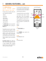
4.7 Primary Screen 7: SHARED DATA
Access SHARED DATA screen
(GPS MAP / PLANNING → POSITION
INFO → trip log → MAIN MENU →
COMPASS → SHARED DATA)
The SHARED DATA screen allows you
to use Bluetooth wireless connectivity
to share route data with other nearby
Active 12's. To move Routes between
devices, they have to have been
previously marked as "Share" in the
Route Edit screen.
Operation: Selection of this screen
will initiate a scan for nearby Active
12's. Other Bluetooth devices will not
be visible on this screen.
MY SHARED DATA screen also allows
access back to the Routes Menu
screen, and the ability to Unshare
items.
Fetch Data. Back on the SHARED
DATA screen, items that have been
made shareable by other Active 12's
can be viewed by highlighting that
device using the joystick, and then
either a centre press of the joystick
or the Select button will take you to
their "catalogue" data. Press Fetch to
transfer that item to you device. As the
transfer occurs an information box will
display "Data downloading in progress
... Please wait".
Lists all nearby
Active 12's
Lists your Routes marked
for sharing
Main List: The list will display the User
Name and ID number for all nearby
Active 12's that have Bluetooth turned
on. The blue signal strength bars on
the right hand side range from 1-5
bars.
This Device: Your device will always
be at the top of the list. Either centre
press the joystick, or the Select button
to display the list of Routes that you
have previously marked as "Share". To
make an item shareable or not, locate
it in your ROUTES menu, press Edit,
then Share / Unshare.
Select an Active 12 to view
their shareable routes.
© Satmap Systems Ltd
23
Press Fetch to get a route.
© Satmap Systems Ltd 2014
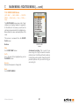
4.7 Primary Screen 7: SHARED DATA (... cont)
Imported Data. Once an item has
been fetched to your device, it will be
placed in the ImportedData folder on
the Internal memory. From here all the
standard ROUTES MENU functions
are available. The route that you have
just imported should be highlighted.
strength.
Shareable - by default. All imported
data is flagged as shareable by
default. If you wish to change this,
Edit the route and change the status
to "Not Shared"
SHARED DATA - Other buttons:
Lists all nearby
Active 12's
Other Buttons
Bluetooth Devices: this will hop to
a screen where all Bluetooth devices
can be observed - including Bluetooth
Smart Low Energy fitness sensors and
other BT devices generally.
Turn Bluetooth Off / On: When turned
Off - the BT icon will disappear from
the Status Bar and only the shareable
data on your own device can be
inspected. The SETTINGS button will
hop to the SETTINGS / Bluetooth
screen.
Refresh: This button will rescan for
nearby Active 12's - and typically takes
about 10 seconds. You may see the
list move about & reorder, depending
on new devices in range and signal
© Satmap Systems Ltd
Bluetooth Off
24
© Satmap Systems Ltd 2014
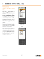
4.8 Primary Screen 8: GPS STATUS
Access GPS STATUS screen
(GPS MAP/PLANNING → POSITION INFO →
TRIP LOG → MAIN MENU → COMPASS →
SHARED DATA → GPS STATUS)
This is the screen that is first displayed when
switching on the unit (unless there is already
a map card inserted in which case the unit will
briefly show the Map Packs screen.
The elliptical diagram represents the sky
above you where North is the top of the ellipse.
Satellites visible to the unit are allocated
numbers and also shown on the bar chart.
Yellow bars indicate the unit can see a satellite.
The bars change to orange when the unit has
acquired a lock. There are also indications of
Signal to Noise Ratio (Av SNR and Max SNR).
Before acquiring a lock, details of your last
known position, with time, date, and grid
reference are shown at the top of the screen.
(Grid reference format options are given in
GPS Settings, ‘Position Display Format’).
Once you have a lock, your current coordinates
and elevation are shown. As a guide, a
minimum of four satellites are needed to
acquire a lock.
© Satmap Systems Ltd
To access the GPS STATUS screen from the
GPS MAP screen, keep pressing the Primary
Screens button (front right button) until you
reach the GPS STATUS screen.
Signal
indicator
The signal indicator (either red cross or green
signal icon) indicates the strength of signal
received by the unit. The GPS indicator
caption at the bottom of the screen either says
‘Acquiring GPS’ or gives accuracy to within a
certain distance.
Average
Signal
to Noise
Ratio
(SNR)
If the unit is receiving a poor signal e.g. under
wet tree canopy, it may only be able to give
two dimensional data, i.e. no elevation data.
Under these circumstances the elevation
caption at the top right of the screen will show
‘2D’ instead of an elevation figure. The signal
received icon at the top left will also show a
single green crescent plus ‘2D’.
GPS Map
Satellitesʼ
atomic
clock time
Maximum
Signal to
Noise Ratio
GPS Status
Primary
Screens
Buttons:
GPS Map
Return to GPS MAP
Primary Screens
Go to PLANNING screen and scroll through
primary screens
25
© Satmap Systems Ltd 2014
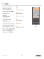
5. POWER OFF Screen
Power Off : Press the long side button on
the right hand side of the GPS to display the
Power Off? screen. The bottom right Power Off
button will totally power down the GPS unit, but
your current data will be saved. Once off, no
GPS logging or trip data will be recorded until
the unit is tuned on again.
Hibernate : This function puts the GPS into
a low power "stand-by" mode. The primary
benefit of this to allow a very fast restart and
GPS re-aquisition. Typically useful over a
lunch break, for instance. After the specified
period, the GPS will do a full "Power Off". In
Hibernate mode, the Active 12 will not log any
further data until the Power button is repressed
and a GPS lock is restored.
Screen Lock : You may wish to lock the
screen to prevent accidental button presses.
From the Power Off? screen - just press the
long Power Button one more time, this will
send you back to previous working screen, and
will place a small yellow padlock icon on the
status bar. Thereafter, pressing any button will
display the Unlock? screen
© Satmap Systems Ltd
POWER Screen, with
Hibernate options
26
LOCK Sceen option.
© Satmap Systems Ltd 2014
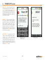
6. MAIN MENU: Settings Menu
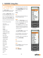
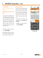
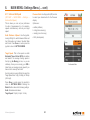
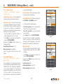
6.1
Access SETTINGS MENU screen
(GPS MAP → MAIN MENU → Settings)
The SETTINGS MENU screen gives you
access to a wide range of settings options.
In addition, use Memory Status to find out
how much RAM/operating memory you are
using. If the consumption is too high, you can
reduce it by adjusting Set Trip Data to 'Hide
Inactive Routes' or only show the start point of
an inactive route ('Show Inactive Routes SP').
The full list of settings options are:
• Power Control
• Advanced Power Control
• Bluetooth
• Elevation
• Backlight
• 2 Data Box Layout
• 4 Data Box Layout (upper)
• 4 Data Box Layout (lower)
• GPS Settings
• Memory Status
• Units and Set Speed
• Compass Settings
• Calibrate Compass
• Set Trip Data
• Volume Control
• Buttons Control
• Panning Speed
• Cycling
• Screen Data Options
• Time Offset
• Enter User Name
• Languages
• About
© Satmap Systems Ltd
At any point, should you wish to exit a settings
screen, either press Map (front left button) to go
to the GPS MAP/PLANNING screen, or press
Back (front right button).
Buttons:
Next
Scroll through menu options. Alternatively use
the joystick to highlight an option.
Default
Takes you to the Default Settings screen with
the option to choose Yes or No. Pressing Yes
takes you to the Default Options screen:
• Choose Clear All to reset all the user defined
settings, trail and GPS data, (including OOIs
and routes) to the factory set defaults. The unit
will then turn itself off.
Figure 7.00
SETTINGS Menu -1
• Choose Reset Settings to reset only the
settings data to the factory set defaults.
(If you choose Yes you will not be able to go
back without choosing one of these options).
Choose No to retain all current settings and
return to the SETTINGS MENU.
Map
Return to last map screen
Select
Either press Select or centre press the joystick
to select the highlighted option
Cancel / Back Return to MAIN MENU
SETTINGS Menu -2
27
© Satmap Systems Ltd 2014
6.
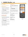
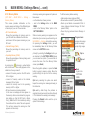
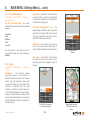
6.2
MAIN MENU: Settings Menu (... cont)
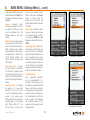
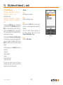
Power Control
(MAIN MENU → Settings → Power Control)
Automatic Power Saving
• Use the joystick, moving left/right to select
desired time the unit will stay powered on for.
• Press Done or centre press the joystick to
return to SETTINGS MENU.
Note: Allowing the unit to power off will cause
it to lose GPS lock. However, if the unit is in
hibernate mode, then it will be able to acquire
a lock very quickly after powering on.
Automatic Screen Turn Off
This is a power saving option.
• Use the joystick, moving left/right to select
desired time before the screen will turn off
leaving the unit still operating.
• Press Done or centre press the joystick to
return to SETTINGS MENU.
Alert When Screen Off
• Use the joystick, moving left/right to toggle
between Off and Screen Alerts Every
Minute.
• Press Done or centre press the joystick to
return to SETTINGS MENU.
With the alerts mode selected the screen will
flash on at 1 minute intervals to remind you the
unit is switched on—particularly useful when
dark.
Pressing the Default button restores the
following settings:
Automatic Power Setting
Off after 120 minutes
Automatic Screen Turn Off
Always On
Alert When Screen Off
Screen Alerts Every Minute
Power Control
Settings
GPS lock will be maintained and the unit will
continue to log your position.
• To instantly re-activate the screen, press any
button, except when the screen is locked. In
this case, use the power button.
© Satmap Systems Ltd
28
© Satmap Systems Ltd 2014
6.
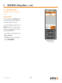
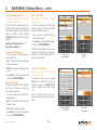
6.3
MAIN MENU: Settings Menu (... cont)
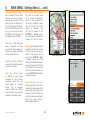
Advanced Power Control
(MAIN MENU → Settings → Advanced Power
Control)
Power Saving Mode
To save power, select Advanced power
saving mode and the screen will update every
four seconds instead of every second.
In this mode Trail Up is disabled and the
Backlight setting has a maximum value of
80%, but can be temporarily be set to 100% by
pressing the backlight button.
• Use the joystick, moving left/right to select
Normal or Advanced.
• Press Done or centre press the joystick to
return to SETTINGS MENU.
© Satmap Systems Ltd
Advanced Power Control
- For Power Saving
29
© Satmap Systems Ltd 2014
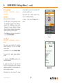
6.
6.4
MAIN MENU: Settings Menu (... cont)
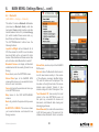
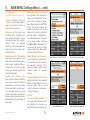
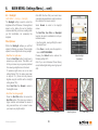
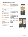
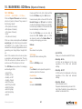
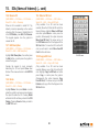
Bluetooth
(MAIN MENU → Settings → Bluetooth)
This Active 12 carries a Bluetooth 4.0 module
(also known as Bluetooth Smart), which has
two bands: Classic (which handles route data
transfer between Active 12's) and Low Energy
(LE, which handles fitness sensor data, e.g.
Heart Rate and Cadence Monitors).
The SETTING/Bluetooth buttons have the
following functions:
Joystick Left/Right will turn Bluetooth On &
Off. When turned On, the BT Icon on the status
bar should flash as the unit search for other
devices. Data transfer and fitness sensor data
will not function whilst Bluetooth is turned off.
Bluetooth Devices will display all Bluetooth
enable devices that are nearby (Classic & Low
Energy).
Done returns you to the SETTINGS screen.
Shared Data hops to the SHARED DATA
screen which allows you to see and fetch other
Active 12 users' route data.
Cancel will cancel the operation and return you
to the SETTINGS menu.
Map returns to the GPS MAP/PLANNING
screens.
Back will go back to the previous that you were
on.
BLUETOOTH SCREEN. This screen allows
you to see local devices - and connect to Low
Energy sensors.
© Satmap Systems Ltd
SETTINGS Menu
SETTINGS / Bluetooth
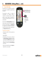
Shared Data, as above, hops to the SHARED
DATA screen.
Refresh, kicks off a Bluetooth refresh scan to
look for new devices nearby. In this version
of the software, previously identified Active
12's and LE devices will be displayed. The
blue bars on the right hand side of the screen
indicate signal strength. Typically 5 bars
indicate a range of 1m and 1 bar approx. 10m.
Turn Bluetooth Off, does exactly that, and
returns to the main SETTINGS screen. At
this point any connected LE devices will
disconnect, and Bluetooth data sharing and
data logging will cease.
Select/Deselect, this controls the connections
to BT LE fitness sensors. This version of the
software allows Bluetooth Smart connection
30
BLUETOOTH screen
© Satmap Systems Ltd 2014
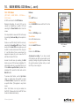
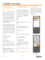
6.
MAIN MENU: Settings Menu (... cont)
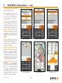
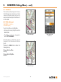
to two types of fitness sensors:
Heart Rate Monitors (HRM), and
bike Speed & Cadence sensors
(Sp/Cad).
Sensors.
Bluetooth
Smart
sensors are optional extras for
the Active 12 GPS units. They
can be purchased from the
Satmap website, or from other
outlets.
Please Note; Currently Satmap
has partnered with the "Wahoo"
brand for these fitness sensors.
When selecting other brands,
please ensure that they support
the Bluetooth 4.0 "Smart" and
"Smart Ready" profiles. The
Active 12 does not support the
ANT+ profile.
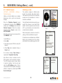
Connecting Step 1. Ensure
that your sensors is activated.
For HRM, this is typically done
by putting the strap around your
chest. For bike Sp/Cad sensors,
typically by spinning the wheel or
pedals.
Connecting Step 2. Providing
the sensor is in range and
activated, the Active should
"see" it on the Bluetooth devices
screen. If not, please press
Refresh and the name of sensor
should appear, in the example
right: "Wahoo HRM v2.1". Use
the joy stick to cursor up and
© Satmap Systems Ltd
down to your desired sensor
device. Either press the Select
button, or centre press the
joystick and a black tick will
indicate that the sensor has been
"Selected".
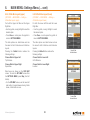
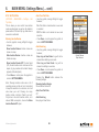
Please Note; Bluetooth allows
only one of each type of sensor
to be selected at any one time.
You can have a HRM and a Sp/
Cad sensor selected, but not two
HRM's.
Connecting Step 3. Wait for a
short period and the black tick
should turn blue. This indicates
that your selected LE device has
now "connected" and sensor
data can be collected. During the
connection process, the BT icon
on the status bar should flash
blue/grey and then turn solid blue
when the connection is made.
Two Sensors "Selected"
One Sensor "Connected"
Troubleshooting.
Very occasionally Bluetooth
can be temperamental! If a
connection is not made on the
first attempt - deselect the BT LE
device, check that your sensor is
activated and in range, and then
reselect the device. Failing that,
turn the Bluetooth fully off, then
back on again, and reattempt
the connection process. If that
continues to fail, please connect
Satmap support.
Two Sensors "Connected"
31
© Satmap Systems Ltd 2014
6.
MAIN MENU: Settings Menu (... cont)
Connecting Step 4. Once a
blue "connected" tick has been
observed, you sensor will then
pass data to the Active 12. This
data may then be displayed in
the 2 & 4 data boxes that appear
on the GPS MAP screen. To set
this up, you will need to select
SETTINGS / 2/4 BoxLayout and
the HRM data item (20.HRM).
Data Types : HRM. Heart rate
data is displayed as "beats
per second". Future editions of
software will display Heart Rate
Zones, and the such like.
Data Types : Cadence. This is a
measure of the pedal revolutions
per second on a bike.
Data Types : Wheel Speed.
In addition to using speed
calculated by GPS position
movement, cyclist often use
"wheel speed" as a reliable
backup. This is especially
useful if a GPS lock is difficult
for any reasons (e.g. very thick
woodland or the urban jungle).
© Satmap Systems Ltd
Set up for Wheel Speed.
This relies on a default value
for the wheel circumference,
which is then multiplied by
the wheel revolutions output
from the sensor. The default
setting
is
2,096mm,
and
this can be changed in the
SETTINGS / Cycling screen.
Use the joystick to navigate the
numbers and set the values.
Data Output. HRM and cadence
data will be stored on the Active
12. After your activity, save your
data for later upload. This is
done via the TRIPLOG / Menu
/ Convert options. Your data
containing the HRM and cadence
values will be stored in a TCX file
(e.g. MyRoute1.tcx). You will be
able to see these files when you
use the SatSYNC PC application
to upload your data.
Sensor data displayed
About TCX files. This is an
industry standard format that is
accepted by a wide variety of 3rd
party activity storing and sharing
web sites. These TCX files can
contain location and speed data,
along with a wide variety of
fitness related data items.
SETTINGS / Cycling
Set your Wheel Circumference in mm.
32
© Satmap Systems Ltd 2014
6.
6.5
MAIN MENU: Settings Menu (... cont)
Elevation
Elevation from Maps. Each map
is supplied with a "height data set"
that provides spot heights at regular
horizontal intervals (post spacing).
Typically
these
are
between
50m-100m. This method works well
when the ground is less steep, with
fewer cliffs around.
Setting "Elevation" source. Data
that is stored for later upload has a
single set of elevation data. You can
control this by setting its source.
Select Elevation from the SETTINGS
screen. The top box indicates the
Elevation data source and can be
changed by moving the joystick left
and right (when it is highlighted by
the orange background). A selection
can be made between "Elevation
from Maps, GPS or Pressure". The
first two settings require no further
action - just press Done, Back or Map
to continue with the GPS use.
Elevation from GPS. This method
uses height data supplied by the
GPS itself, and works best when
there is a good, unobstructed view of
a large portion of the sky. The data
can be quite variable in forests and
amongst tall buildings.
Setting Elevation from Pressure.
To work effectively, elevation from
the barometric altimeter needs to
be calibrated at intervals. This is
because changing weather would
otherwise affect the elevation
reading.
Elevation from Pressure. The
highly accurate barometric altimeter
can be used to assist with elevation
calculations, and uses the principle
that pressure falls as elevation rises.
It is especially useful over short
periods of time where the weather is
relatively stable, since pressure also
generally falls when bad weather is
approaching.
Altimeter Calibration: Auto. On this
setting the Altimeter is recalibrated
against the Map elevation every 2
hours (by default). This is a good
setting for normal use and requires
no further user input.
(MAIN MENU / Settings /Elevation)
Overview. The Active 12 gives you
3 options for calculating elevation
values. All are useful, but they do
have some pros and cons.
© Satmap Systems Ltd
Select "Elevation" from SETTINGS
Select Elevation data source
Info Box:
"Last Successful Calibration." If
a long time has elapsed since the
last calibration, the accuracy may
have drifted due to weather change:
33
Auto calibration setting
Select Recalibration frequency
© Satmap Systems Ltd 2014
6.
MAIN MENU: Settings Menu (... cont)
it would be wise to recalibrate the
device as described below.
Auto Recalibrate Frequency. The
left / right joystick function can be
used to toggle the recalibrate time
interval between 2 / 4 / 6 / 8 hours.
"Calibrate Now" button will calibrate
the local pressure against your
current Map Elevation, and record
the date and time for future reference.
Manual Calibration. Should you
wish to have more control over the
recalibration of the altimeter, select
"Manual" using the joystick, and then
Select.
Method 1: Map/GPS Elevation. This
will simply use the Map elevation for
calibration (or GPS height data for no
map data is available).
2/4/6/8 Hour Intervals
Manual: Using Map/GPS
Precise Calibration: Known Elevation
Method 2: Known Elevation. This
allows you to enter you own known
elevation for a precise calibration.
Typically you might be at a Trig Point
or a map location where you are sure
of the exact height. Use the joystick
to scroll through and set the values.
Viewing Elevation Data. On the
GPS MAP screen the Data Boxes
can be used to view your elevation
data. It is even possible to select
all 3 types of elevation data for
comparison, however, only one set
of elevation data can be saved in the
TRIP LOG for display and upload.
© Satmap Systems Ltd
View your Elevation data
Set Your Known Height
34
Trip Elevation data
© Satmap Systems Ltd 2014
6.
6.6
MAIN MENU: Settings Menu (... cont)
Backlight
(MAIN MENU → Settings → Backlight)
The Backlight setting is used to control the
brightness of the GPS screen. It has significant
impact on the battery life and is therefore
recommended that you choose a setting which
you find comfortable, not necessarily the
brightest.
Filter Options:
Within the Backlight settings you will find
options for filtering your screen. These include
options for use at night and in strong sunlight:
• Red Filter: for night vision
Press the Red Filter button for night use to
preserve your night vision. This adds a red
tint to your screen so your eyes are protected
from viewing a bright screen in the dark.
To preserve night vision, use a low level
setting. Below 10%, the scale goes down
in steps of 2%. (Some text may become
illegible using the red filter with a backlight
setting below 10%).
Note: With the Sun Filter your screen loses
some intricate map details in order to enhance
the visibility of the map in sunlight.
Select Normal to return to the daylight
screen.
The Red Filter, Sun Filter and Backlight
level can be used in combination to suit your
individual needs.
• Use the joystick, moving left/right to select
the desired level.
• Press Done or centre press the joystick to
return to SETTINGS MENU.
Pressing the Default button restores the
following setting: 90%
Adjust backlight
brightness
Note: If you are in Advanced Power Saving
mode, the Backlight setting cannot go beyond
80%.
Select Sun Filter, then Normal to return to
the daylight screen.
• Sun Filter: for strong sunlight
Press the Red Filter button to access the
Sun Filter option. This gives your screen a
higher contrast and increases the levels of
red, green and blue, so it is easier to view
your map in very bright sunlight.
Normal
© Satmap Systems Ltd
Red Filter
35
Adjust brightness
Sun Filter
© Satmap Systems Ltd 2014
6.
6.7
MAIN MENU: Settings Menu (... cont)
Screen Data Capture
Screenshots may be captured as jpeg files
and accessed in SatSYNC, listed with time/
date details.
Backlight Boost and
Screen Data Capture
This might be useful in a variety of
circumstances. For example, sending a
screenshot of a particular location to another
person or using a series of screenshots in
conjunction with timed digital photos for use in
a presentation.
Camera icon
Briefly replaces
icons next to the
battery
Press and hold the Backlight Boost button for
three seconds; a camera icon briefly replaces
the icons next to the battery (i.e. Stop/Record
icon, toggle icon). A beep sounds to indicate a
successful screenshot capture, depending on
your Beep Alert Count setting.
To access your screenshot:
• Connect your Active 12 to the computer via
a USB cable.
• Open SatSYNC.
• Screenshots are found in the root folder of
the Internal Storage or SD Card. (By default
it is saved to the SD Card folder, if the SD
card is in the unit and is not write-protected.
Otherwise it is saved to the Internal Storage
of your unit).
• Select the screenshot and press Export to
download it to your computer.
© Satmap Systems Ltd
36
© Satmap Systems Ltd 2014
6.
6.8
MAIN MENU: Settings Menu (... cont)
Data Boxes
This is a white overlay that appears in the lower
half of the map screen. It allows you to show
customized information (data) about your trip,
environment and map objects. Available as a 2
or 4 box layout.
6.8.1 2 Data Box Layout
(MAIN MENU → Settings →
2 Data Box Layout)
For both the Left Box and the Right Box:
• Use the joystick, moving left/right to select the
desired option.
• Press Done or centre press the joystick to
return to SETTINGS MENU.
2 Data Box Layout
Select items for the
Data Boxes
The data options are listed below and are
the same for both 2 data box and 4 data box
layouts.
Pressing the Default button restores the
following settings:
Choose Data for Left Box
Heading
Choose Data for Right Box
Elevation
4 Data Box Layout
© Satmap Systems Ltd
37
© Satmap Systems Ltd 2014
6.
MAIN MENU: Settings Menu (... cont)
6.8.2 4 Data Box Layout (upper)
6.8.3 4 Data Box Layout (lower)
For both the Upper Left Box and the Upper
Right Box:
For both the Lower Left Box and the Lower
Right Box:
• Use the joystick, moving left/right to select the
desired option.
• Use the joystick, moving left/right to select
the desired option.
• Press Done or centre press the joystick to
return to SETTINGS MENU.
• Press Done or centre press the joystick to
return to SETTINGS MENU.
The data options are listed below and are
the same for both 2 data box and 4 data box
layouts.
The data options are listed below and are
the same for both 2 data box and 4 data box
layouts.
Pressing the Default button restores the
following settings:
Pressing the Default button restores the
following settings:
Choose Data for Upper Left
Trip Distance
Choose Data for Lower Left
GoTo Distance
Choose Data for Upper Right
Speed Now
Choose Data for Lower Right
Location
(GPS MAP → MAIN MENU → Settings →
4 Data Box Layout: upper)
(GPS MAP → MAIN MENU → Settings →
4 Data Box Layout: lower)
Upper Data
box selections
Data boxes are shown on the GPS MAP
screen. To reach the GPS MAP screen from
the SETTINGS MENU, press Map (front left
button).
• On the GPS MAP screen, use the lower left
side button to toggle between having 2 data
boxes, 4 data boxes or none.
Lower Data
box selections
© Satmap Systems Ltd
38
© Satmap Systems Ltd 2014
6.
MAIN MENU: Settings Menu (... cont)
6.8.4 Options for 2 & 4 Data Boxes
(GPS MAP → MAIN MENU → Settings →
2/4 Data Box Layout)
The following data options are available for
each box in both the 2-box and 4-box layouts.
Move the joystick left/right to select the desired
option, and then press Done or centre press
the joystick to complete. For each data option,
a summary descriptor is given on-screen.
Heading
Direction of travel, given in either Degrees (M
– Magnetic North, G – Grid North, T – True
North), Cardinal points (e.g. N, NNE), or milradians. See Compass Settings.
Location
GPS position given by either OSGB
(Ordnance Survey GB); UTM; Degrees
decimal; Degrees, minutes decimal; Degrees,
minutes, seconds decimal; British Grid.
See GPS Settings for other formats.
GoTo Bearing
Bearing to your “Go To” point. See Position
Info, (Set as GoTo option).
GoTo Distance
Distance to GoTo point, either imperial or
metric. See Units and Set Speed.
GoTo ETA
Estimated Time of Arrival at GoTo point.
GoTo Time
How long to reach GoTo point.
© Satmap Systems Ltd
GoTo VMG
VMG (Velocity Made Good) is the actual speed
you are making toward your chosen location
(POI, Next WP or GoTo point (AOI, LOI, POI,
WP or any unidentified point on the map),
rather than your simple forward speed.
POI* Time
Time until nearest POI/LOI/AOI.
Bearing Next WP
Bearing to the next waypoint.
Bearing to End
Bearing to the route end.
Distance Next WP
Distance to the next waypoint.
Distance to End
Distance to route end (along the route).
ETA to Next
Estimated Time of Arrival at next waypoint.
ETA to End
Estimated Time of Arrival at route end.
Time Next
How long to reach next waypoint.
Time to End
How long to get to route end.
VMG Next
Velocity Made Good to next waypoint. See
GoTo VMG summary above.
VMG End
Velocity Made Good to route end. See GoTo
VMG summary.
WP Name
Name of next waypoint.
Route Cross Track Error
This is the distance between the planned
blue/yellow route and the snail trail. It is most
relevant for aircraft (cross wind effects) and
nautical applications (effects of currents).
Nearest POI*
Name of nearest POI/LOI/AOI.
Bearing to POI*
POI* VMG
Velocity Made Good to nearest POI/LOI/AOI.
See GoTo VMG summary.
Bearing to nearest POI/LOI/AOI.
Route Distance
Total distance of the active route.
Nearest POI* Distance Distance to nearest
POI/LOI/AOI.
Route Done
Percentage of route travelled so far.
POI* ETA
Time of arrival at nearest POI/LOI/AOI.
39
© Satmap Systems Ltd 2014
6.
MAIN MENU: Settings Menu (... cont)
6.8.4
Options for 2 & 4 Data Boxes
(... cont)
Route Name
Name of route.
Average Moving
Average moving speed.
Average Speed
Average speed overall; total distance divided
by total time.
Max Speed
Maximum speed.
Trip Distance
Total trip distance. See Time Moving summary
above.
Trip Time
Total trip time. See Time Moving summary
above.
GPS Accuracy
Accuracy of GPS within a certain distance.
Position as Lat. Long.
Position is given in degrees latitude and
longitude.
Speed Now
Current speed.
Elevation
Current height above sea level. See GPS
Settings (section 7.09).
Sunrise
Time of sunrise.
Time Now
Time of day.
Sunset
Time of sunset.
Date
Date today.
Moon Phase
An icon is displayed along with the percentage
of a full moon.
Total Ascents
Cumulative total of height (altitude) gained.
Time Moving
Time spent moving, as recorded by the Trip
Log (section 6.03). This will be a cumulative
total until the Trip Log is reset.
Stopped Time
Time spent not moving. See Time Moving
summary above.
© Satmap Systems Ltd
* In the data boxes, data options mentioning
POIs also refer to any reference point of an
LOI and AOI (usually the point at the start of
the name).
Total Descents
Cumulative total of height (altitude) lost.
Max Altitude
Maximum height (altitude) attained.
Min Altitude
Minimum height (altitude) attained.
40
© Satmap Systems Ltd 2014
6.
6.9
MAIN MENU: Settings Menu (... cont)
GPS Settings
(GPS MAP → MAIN MENU → Settings →
GPS settings)
Position Display Format (ie. grid reference
format)
• Use the joystick, moving left/right to select
from OSGB (Ordnance Survey GB); German
Grid; UTM; MGRS; GARS; CH1903/LV03
Swiss Grid; Swedish Grid RT90; French Grid
Lambert 2E; French Grid Lambert93; Irish
Grid ITM; Irish Grid IG; Pakistan MG; New
Zealand TM; Degrees decimal; Degrees,
minutes decimal; Degrees minutes, seconds
decimal; British Grid.
GPS Used as Heading at
The Active 12 has an electronic compass
(good when stationary) and a GPS compass
(good when in motion), and switches between
the two at a preset speed. In this setting you
are able to select the speed at which the GPS
compass overrides the electronic compass.
The GPS compass is more accurate the faster
you go.
• Use the joystick, moving left/right to select
from Never, then from 1 kph/0.5 mph to 16
kph/10 mph.
• Press Done or centre press the joystick to
return to SETTINGS MENU.
• Press Done or centre press the joystick to
return to SETTINGS MENU.
Select Correct Position
Format for Country
OSGB grid references are given to 10 figures.
If you are working to 6-figure grid references,
set the last 2 digits of each number set to 0.
© Satmap Systems Ltd
Figure 7.09
41
© Satmap Systems Ltd 2014
6.
MAIN MENU: Settings Menu (... cont)
6.10 Memory Status
(GPS MAP → MAIN MENU → Settings →
Memory Status)
This screen provides information on the
memory usage and status of the different types
of memory on your unit. These include:
• SD Card Information
Shows the percentage of memory used on
your SD card. Also indicates the total size
and amount of free space remaining on your
SD card.
• Internal Storage (Flash)
Shows the percentage of memory used on
your unit.
• Operating Memory (RAM)
Shows the percentage of memory being used
to operate the unit.
A warning icon
(showing a yellow bubble
with a black exclamation mark) appears on the
status bar of every screen if:
• amount of memory used on the SD card is
95% or higher.
• amount of memory used on the internal
storage is 95% or higher.
• amount of memory used in the operating
memory is 95% or higher.
• SD card is read-only (write-protected).
In this case a message will also appear on
the memory status screen below the progress
bars telling you that the 'SD Card is ReadOnly'. (Make the SD Card writable by sliding
the small switch on side of the card upwards.
This will also remove the warning icon that
appears on the screen).
© Satmap Systems Ltd
A memory warning icon appears in 3 places in
these cases:
• on the status bar of every screen
• next to the Settings button in the MAIN
MENU
• next to the 'Memory Status' option in the
SETTINGS MENU.
When a memory warning icon appears on the
status bar of your screen you will need to go to
MAIN MENU → Settings to check the warning.
On pressing the Settings button, you will
be immediately taken to the Memory Status
screen on the SETTING screen.
(Usually by selecting the Settings button you
are directed to the SETTINGS MENU where
you can select an option. If you would like to
access the menu from the Memory Status
screen, press Back).
Move the joystick up/down, or press the Next
button to select a memory option. Move the
joystick left/right to opt in/out of the memory
warning.
To fix the memory status warning:
• Hide inactive routes (reduces RAM)
• Show inactive routes SP (reduces RAM)
• Back up and delete non-essential OOIs &
routes (reduces Internal Storage, SD Card
space & RAM)
• Reset trip log (reduces Internal Storage &
RAM)
Progress bars:
orange: safe usage
green: low usage
purple: high usage
Opt in
Opt out
Back
to get to the
SETTINGS
MENU
Opt in by selecting the yellow icon which
keeps the warning icon message showing in
the status bar.
Opt out by either fixing the problem or
selecting the yellow icon with a red line through
it. This removes the warning icon message.
Pressing the Default button sets the opt in
option for all warnings.
42
© Satmap Systems Ltd 2014
6.
MAIN MENU: Settings Menu (... cont)
6.11 Units and Set Speed
Pressure Units. Use the joystick (L/R) function
to select your desired units for the Pressure
display:
This is where you can set your preference
for units of measurement (i.e. for elevation,
speeds and distances), and set your target
speed.
Options are :
(GPS MAP → MAIN MENU → Settings →
Units and Set Speed)
Units: Distance & Speed. Use the joystick,
moving left/right to switch between Miles and
feet, Kilometres and meters, Nautical Miles
and Knots. Press Done or centre press the
joystick to return to SETTINGS MENU.
a. mBar (millibars)
b. inHg (inches mercury)
c. mmHg (mm of mercury)
d. hPa (Hectopascal)
Target Speed. This is the speed on which
Estimated Time of Arrival (ETA) calculations
are based if the average moving speed in
the trip log (Av. Moving) is zero, i.e. you are
stationary. Once you are moving, your ETA is
taken from your average moving speed if you
have a lock or recently had a lock.
Set desired Units
Use the joystick, moving left/right to select the
Target Speed from 1 kph (0.6 mph) to 100 kph
(62.5 mph).
Press Done or centre press the joystick to
return to SETTINGS MENU. Pressing the
Default button restores the following settings:
Units: Kilometres and meters
Target Speed: 10 kph (6.2 mph / 5.4 kn)
© Satmap Systems Ltd
43
© Satmap Systems Ltd 2014
6.
MAIN MENU: Settings Menu (... cont)
6.12 Compass Settings
(GPS MAP → MAIN MENU → Settings →
Compass Settings)
This controls the data boxes that appear on the
COMPASS screen and POINTER screen, and
how the bearing options are displayed in the
data box on the GPS MAP screen.
There are three norths commonly used in
Great Britain:
• Grid North: the direction of a grid line which
is parallel to the central meridian on the
National Grid.
• True North: the direction of a meridian of
longitude which converges on the North Pole.
• Magnetic North: the direction indicated by a
magnetic compass. Magnetic North moves
slowly with a variable rate and currently is
West of Grid North in Great Britain.
Compass Display
• Use the joystick, moving left/right to select
from Degrees, Cardinal points (e.g. N,
NNE), or mil-radians.
• Press Done or centre press the joystick to
return to SETTINGS MENU.
Grid Magnetic Angle
• Use the joystick, moving left/right to switch
between Manual and Automatic.
manually, select Manual and then press Set.
This will take you onto a new SETTING screen
on which the Grid Magnetic Angle may be
adjusted by moving the joystick up/down.
Pressing the Default button restores the
following setting:
Grid Magnetic Angle Value : W 03
• Press Done or centre press the joystick to
return to Compass Settings screen. Press
Done again to return to SETTINGS MENU.
Bearing Display
• Use the joystick, moving left/right to switch
between Show Grid Bearings and Show
Magnetic Bearings.
Settings for Grid Magnetic
Angle
• Press Done or centre press the joystick to
return to SETTINGS MENU.
Pressing the Default button restores the
following settings:
Compass Display
Degrees
Grid Magnetic Angle
Manual
Bearing Display
Show Grid Bearings
Manual or Automatic
Enter values for Manual
selection
Press Done to select Automatic.
If you want to set your Grid Magnetic Angle
© Satmap Systems Ltd
44
© Satmap Systems Ltd 2014
6.
MAIN MENU: Settings Menu (... cont)
6.13 Calibrate Compass
(GPS MAP → MAIN MENU → Settings →
Calibrate Compass)
Ideally you should calibrate your compass
before every trip to get the most accurate
bearings.
When the ‘Calibration Required’ prompt
is displayed at the bottom of the COMPASS
screen, go to the Settings menu and select
Calibrate Compass. Follow the on-screen
instructions. Press Cancel to return to the
SETTINGS MENU.
Note: This screen may also be accessed from
the COMPASS screen.
1) Hold GPS level
2) Press Start
Calibrating on a bike
The electronic compass is affected when
brought into proximity with metal objects.
This means that once the GPS unit has been
mounted onto the handlebars of a bike, it
should be re-calibrated.
To do this follow the instructions exactly as you
would if the unit were in your hands. When
asked to turn the compass in two full circles
(720°), you should pick up the bike with the
unit and rotate it as indicated.
Calibrate Compass
Calibrate Compass
- Option 1
- Option 2
When subsequently removed and used for
walking, a further recalibration is required.
It should also be re-calibrated when a different
battery type is inserted, due to the varying
metal content from one battery type to the next.
3) Turn device around in TWO full circles (720
degrees)
4) Press Stop when completed turning or
Cancel to quit.
An on-screen message ‘Keep turning’ is
replaced with ‘Completed. Press Stop’.
Note: When in motion it is better to use the
GPS compass over the electronic compass.
The GPS compass requires forward motion
to provide a heading; it will not work when
static. See GPS Settings (section 7.09) to
control when the GPS compass overrides the
electronic compass at a preset speed: 'GPS
Used as Heading at'.
© Satmap Systems Ltd
45
© Satmap Systems Ltd 2014
6.
MAIN MENU: Settings Menu (... cont)
6.14 Set Trip Data
(GPS MAP → MAIN MENU → Settings → Set
Trip Data)
Auto Clear Trail Data
• Use the joystick, moving left/right to toggle
between;
This is where you can control how inactive
routes are displayed, as well as the deletion/
preservation of trail and trip log data when a
new route is activated.
On: Trail data is cleared when a new route
is selected.
Showing Inactive Routes
• Use the joystick, moving left/right to toggle
between;
• Press Done or centre press the joystick to
return to SETTINGS MENU.
Show Inactive Routes: Inactive routes are
shown on maps.
Hide Inactive Routes: Inactive routes are
hidden on maps.
Show Inactive Routes SP: The start point
(SP) of each inactive route is shown on the
maps. (A gray marker with a black triangle
appears at the start point).
• Press Done or centre press the joystick to
return to SETTINGS MENU.
Note: Showing inactive routes uses a lot of
operating memory on the unit, so it is important
to keep this selection to a minimum, as it will
slow down your unit. Showing too many
inactive routes could also 'freeze' your unit.
Only show a few short inactive routes, or to
reduce RAM consumption, choose the Show
Inactive Routes SP option.
© Satmap Systems Ltd
Off: Trail data is not cleared on new route
selection.
Auto Reset Log
• Use the joystick, moving left/right to toggle
between;
Keep Log on New Route: Log will not be
cleared when starting a new route.
Control Data on
Map Screens
Clear Log on New Route: Log will be
cleared on starting a new route.
• Press Done or centre press the joystick to
return to SETTINGS MENU
Pressing the Default button restores the
following settings:
Showing Inactive Routes
Show Inactive Routes SP
Auto Clear Trail Data
Off
Auto Reset Log
Keep Log on New Route
46
© Satmap Systems Ltd 2014
6. MAIN MENU: Settings Menu (... cont)
6.15 Volume Control
(GPS MAP → MAIN MENU → Settings →
Volume Control)
Audio Playback Volume - This is intended for
volume control when using the audio jack.
Beep Alert Count - The unit will beep when
it encounters WayPoints, Points Of Interest,
GoTo Points or Routes. It will also beep when
a map card is inserted or a screenshot is
captured. You are able to customize how many
beeps sound in these instances:
• Use the joystick to select the number of
beeps, ranging from 1 to 10, or mute.
• Press Done or centre press the joystick to
return to SETTINGS MENU.
Pressing the Default button restores the
following settings:
Audio Playback Volume: 70%
Beep Alert Count: Three Beeps
Note: You cannot control the volume of the
beeps.
6.16 Button Control
(GPS MAP → MAIN MENU → Settings →
Button Control)
The 4 side-press or 2 front-press buttons on
the unit enable one-handed operation and are
multifunctional, with variable keys depending
on the screen displayed. You are able to
customize the operating of your unit and tailor
it to fit your needs, i.e. how many clicks you
want the buttons to operate with, and whether
© Satmap Systems Ltd
you are right/left handed.
Key Click Sound - This function only operates
in conjunction with headphones.
Hidden Map Buttons - This function applies to
the GPS MAP or PLANNING screens.
• Use the joystick to toggle between;
Two Click operation: click to reveal button
function then click again for action.
One Click operation: one click activates
button instantly.
• Press Done to return to SETTINGS MENU.
Note: The 'Two Click' operation is particularly
useful for beginners, as they will be able to
see the gray icon that appears on the screen
before the button takes the intended action.
Audio jack playback
volume
Button Handling • Use the joystick, moving left/right to toggle
between Right Handed and Left Handed
operation.
• Press Done or centre press the joystick to
return to SETTINGS MENU.
Pressing the Default button restores the
following settings:
Key Click Sound: Off
Hidden Map Buttons: One Click
Button Handling: Right Handed
47
Audio jack - key click
sounds
© Satmap Systems Ltd 2014
6. MAIN MENU: Settings Menu (... cont)
6.17 Pan and Zoom Speed
(GPS MAP → MAIN MENU → Settings →
Panning Speed)
Set Pan and Zoom Speed This control
allows the Pan and Zoom rates to be adusted
between:
Very Slow
Slow
Medium
Fast
Very fast
Use the joystick to cursor leaft and right to
your desired setting. The default settings is
Medium.
6.18 Cycling
(GPS MAP → MAIN MENU → Settings →
Cycling)
Introduction - The Bluetooth wireless
connectivity allows for the connection of
Bluetooth Smart bike speed and cadence
sensor units (sold separately). Bike speed
is calculated directly from the wheels, while
"cadence" is calculated from the pedal
revolutions. Generally, the speed data given
by the GPS will adequate for most purposes,
however, in certain conditions (thickly wooded
areas and near tall buildings) the wheel speed
data (for bike riders) will give a nore stable and
accurate reading.
© Satmap Systems Ltd
Sensor Unit - Sends back "wheel revolutions
per second" data. To turn this into speed data
it needs to be multiplied by the circumference
of the bike wheel being used.
Set Wheel Circumference in mm - The
default setting is 2096mm, which is generally
good for most road bike (700C) wheels, but will
need to be adjusted for other types of bikes
with different size wheels and tyres.
Wheel size? - If you are unsure of your wheel
size, you can either measure this directly, or
refer to the bike manufacturer's documentation.
Panning Speed
Options
Set in mm - In this edition of the software
the wheel size needs to be entered in mm,
although speed can be displayed in metric or
imperial.
Set Wheel Circumference
for Wheel speed data
48
Display wheel speed on
GPS MAP screen data
Boxes
© Satmap Systems Ltd 2014
6.
MAIN MENU: Settings Menu (... cont)
6.19 Screen Data Options
6.20 Time Offset
This controls the automatic display of
the POI details screen and the display of
POI names, waypoint names, and route
names (i.e. 'titles') on maps. Pressing
the Default button restores the following
settings:
This function allows you to vary the time
setting in relation to GMT (e.g. for British
Summer Time add one hour).
(GPS MAP → MAIN MENU → Settings
→ Screen Data Options)
Auto Show POI Information: Off
Show Titles on Maps: On
Auto Show POI Information
• Use the joystick, moving left/right to
switch between;
(GPS MAP → MAIN MENU → Settings
→ Time Offset)
• Use the joystick, moving left/right to
select the time offset.
• Press Done or centre press the joystick
to return to SETTINGS MENU.
GPS/UTC time (appears in the on-screen
descriptor) is the same as Greenwich
Mean Time, GMT. An explanation of UTC
is given in the glossary.
POI Info on
Map screens
Set Time
offset
Enter User Name
in Text Box
Press Done
to complete
On: POI overlay data is automatically
shown when nearby.
Off: POI overlay data is not automatically
shown.
• Press Done or centre press the joystick
to return to SETTINGS MENU.
Show Titles on Maps
These are the names of POIs, waypoints
and routes, and appear as white text
within a black rectangle.
• Use the joystick, moving left/right to
switch between;
On: POIs, waypoints and route names
shown on maps.
6.21 Enter User Name
(GPS MAP → MAIN MENU → Settings
→ Enter User Name)
This function allows you to set a User
Name for your device. This name is
primarily used in the SHARED DATA
screens to identify other nearby Active
12s.
After a full default factory reset - the
device will normally ask you to set a User
Name.
Off: Names not shown on maps.
• Press Done or centre press the joystick
to return to SETTINGS MENU.
© Satmap Systems Ltd
49
© Satmap Systems Ltd 2014
6.
MAIN MENU: Settings Menu (... cont)
6.22 Languages
(GPS MAP → MAIN MENU → Settings →
Languages)
Languages
Select your preferred language:
• Use the joystick, moving left/right to select
the operating language from English to
English (US), Nederlands (Dutch), Norsk
(Norwegian), Svenska (Swedish), Français
(French), Deutsch (German), Italiano (Italian),
Español (Spanish), Català (Catalan).
contact Satmap support and an Upgrader SD
card will be mailed to you.
Please Note: The 1st relase sofware for the
Active 12 is Version 2.0.xxxx
All Active 12 GPS have "Platform 29", or
higher.
• Press Done or centre press the joystick to
return to SETTINGS MENU.
Select desired
Language
6.23 About
(GPS MAP → MAIN MENU → Settings →
About)
This screen gives details of the software
version installed on your unit and Satmap
contact details.
Press Done to return to the SETTINGS MENU.
To check for the latest software updates,
please:
1. Download the SatSYNC application from
the Satmap website.
2. Connect your Active 12 to your PC, and
SatSYNC will automatically check if software
updates are available. You will be asked if you
wish to update your device.
System info on
About screen
Alternatively, if you do not use a PC, please
© Satmap Systems Ltd
50
© Satmap Systems Ltd 2014
7. MAIN MENU: ROUTES MENU
7.1
ROUTES MENU Screen
(MAIN MENU → ROUTES MENU)
The ROUTES MENU contains the listing of
routes, stored in a series of folders.
Buttons:
Edit. Go to ROUTE EDIT screen
View. Go to ROUTE MAP screen
By default, the first route created is entitled
‘My Route 1’. The routes following are titled
in numerical order, i.e. 'My Route 2', (unless
you have imported a prenamed route to your
unit from an external mapping system). You
can rename the title of your route via the Edit
button.
Map. Return to GPS MAP screen
When a trail is converted to a track it is also
saved in the ROUTES MENU and is allocated
a default title including the year, month, day,
time and distance (e.g. 2010-08-14_16:35
15.6km). A track is a route derived from a trail
that has already been made.
Create New Route. Go to CREATE ROUTE
(section 8.01)
Up folder / Select / Activate / No route active.
Move up to a higher level folder, or when a
route is highlighted, toggle between activating
it and selecting no route active.
Two storage areas
Back. Return to MAIN MENU
Accelerated scrolling: If you have several
routes in one folder you are able to scroll
quickly by holding the joystick up/down. Keep
the joystick pressed up/down until you reach
the file you are looking for.
Route listing
© Satmap Systems Ltd
51
© Satmap Systems Ltd 2014
7.
7.2
MAIN MENU: ROUTES MENU (... cont)
Active and Inactive Routes
There are three ways to 'activate' a route:
• Highlight the route in the ROUTES MENU
and press Activate. An active route is
indicated by a tick next to the route name.
To deactivate, highlight the ticked route
name and press No route active.
• Alternatively you can go to the ROUTES
MENU, press View and then Start, which
activates the route automatically.
• If you can see the route on the GPS MAP or
PLANNING screen, centre press the joystick
anywhere on the route. This will bring up the
Choose Information Type window (section
11.00). Select the route, and then move the
joystick left/right to highlight the green tick.
An activate route has relevant data choices
available for display on the GPS MAP screen
in either 2 or 4 data box overlays. Refer to
MAIN MENU → Settings → Set Trip Data to
control whether changing an activated route
during a trip will reset the log data.
When active, the route is shown as a yellow
or blue highlighted line with red arrowheads
indicating the direction of travel. Inactive
routes are shown as gray highlighted lines
when displayed.
7.3
Following a Route
A route is made up of individual waypoints,
shown as small green circles which turn blue
as you approach the next waypoint. The
route colour can be either blue or yellow, with
varying transparency, depending on the active
route colour chosen. The default route colour
is blue.
To follow a route, you need to first 'activate' it.
As you begin to follow the yellow/blue route,
the next waypoint along turns blue. The current
leg between waypoints is shown to have blue
edging and blue arrowheads. As you approach
this point, the waypoint name is displayed and
the unit will beep. As you pass this waypoint
it will turn from blue to green, and the next
waypoint marker will turn blue, and so on.
Route seleted =
"Activated"
Active route
Inactive route
Inactive routes may be hidden or have just
their start points displayed.
Note: Showing your inactive routes will take up
operating memory.
"Choose Info
Type" box
Figure 8.00b
© Satmap Systems Ltd
52
© Satmap Systems Ltd 2014
7.
7.4
MAIN MENU: ROUTES MENU (... cont)
Create New Route
(MAIN MENU → ROUTES MENU → Create
New Route)
From the MAIN MENU, select the Routes
Menu and press Create New Route. This
takes you to the CREATE ROUTE screen
where you will be able to plot routes by laying
down a series of waypoints. Zoom in for
greater accuracy in placing waypoints.
Alternative ways to create a route:
GPS MAP → POSITION INFO via centre
press → Create New Route
or
GPS MAP → PLANNING → ROUTES MENU
via lower left button → Create New Route
Buttons:
Add Waypoint*
Press the button or centre press the joystick
Remove Waypoint
Press the button or centre press the joystick
ROUTES MENU
Return to ROUTES MENU
Zoom
Zoom in and out
Done
Press when route is finished, unless you have
‘closed’ the route.
© Satmap Systems Ltd
If there is an SD card in the unit and it is not
write-protected, by default the route will go into
the SD Card folder. If there is no SD card in
the unit, by default the route will go into the
Internal Storage folder.
You can create route folders using SatSYNC.
To create a new route in an existing folder, you
will need to select the folder in the Routes
Menu and press Create New Route from
there.
The start point of a route has an icon with a
forward arrowhead in a yellow bubble. The
end of a route has an icon with a chequered
flag in a yellow bubble.
Press Done or press the lower left button to
return to the ROUTES MENU.
To view the route, highlight it and press View;
a route map plus route length is shown.
Note: Folders are only visible if they contain a
minimum of one route or OOI.
The Add Waypoint button has 3 functions:
1. To add a waypoint.
2. To click on an existing waypoint and drag it
to another location.
3. To close the route (i.e. connect the last
waypoint to the start point) if the last
waypoint is very close to the start waypoint.
The centre cross turns green inside the orange
location icon when you are on the CREATE
ROUTE screen to indicate you are ready to
add waypoints. Place waypoints wherever your
planned route changes direction. Waypoints
are shown as green dots. As waypoints are
laid down, a yellow/blue highlighted route is
created. To remove waypoints, position the
green cross over a waypoint and press the
Remove Waypoint button.
Finish
Start
Add
Waypoint
Zoom
In
Remove
Waypoint
Zoom
Out
ROUTES
MENU
CREATE
ROUTE screen
Done
Route Start
Route End
53
© Satmap Systems Ltd 2014
7. 7.5
MAIN MENU: ROUTES MENU (... cont)
Route Edit Screen
(GPS MAP → MAIN MENU → ROUTES MENU
→ (folder/route) → Edit)
Alternative access:
(GPS MAP/PLANNING → click on route →
Choose Information Type → select route via
centre press → ROUTE MAP → Edit)
To access the ROUTE EDIT screen, highlight
the route to be edited in the ROUTES MENU
(section 8.00), and press Edit.
In selecting either Edit Title or Edit Comments
you will bring up an on-screen keypad. When
using the keypad for labelling, either press
Select or centre press the joystick to select
entries. Use the Shift button for upper case
letters, the More button offers more characters.
Buttons:
Next
Press Next or use joystick to scroll down
options
Map
Return to last map screen
When the title and any comments have been
entered, the ROUTE MAP screen will be
annotated with the new title and comments.
(To get to the ROUTE MAP screen, select
View on the ROUTES MENU screen).
The menu options on the ROUTE EDIT screen
are as follows;
• Edit Title
• Edit Comments
• Reverse Route
• Edit Route Map
• Edit Waypoints
• Edit Active Route Colour
• Delete Route
• Copy
• Move Route to/from SD Card*
• Copy Route to/from SD Card*
ROUTE EDIT
screen
*The last two options on the list become
available only when a mapcard has been
inserted and is not write-protected.
Edit
Either press Edit button or centre press joystick
to access alpha-numeric keypad for labelling.
Note: This button changes depending on the
option selected. Other options include Copy,
Move, Delete, Reverse.
Back
Return to ROUTES MENU
© Satmap Systems Ltd
54
© Satmap Systems Ltd 2014
7.
7.6
MAIN MENU: ROUTES MENU (... cont)
Edit Title
(GPS MAP → MAIN MENU → ROUTES
MENU → (folder/route) → Edit → Edit Title)
When a route is created it is called 'My Route
1' by default (or similar, depending on the
number of existing routes). To rename it, use
Edit Title.
Highlight Edit Title, then either press the Edit
button or centre press the joystick to access
the keypad (section 9.00).
7.7
Edit Comments
(GPS MAP → MAIN MENU → ROUTES MENU
→ (folder/route) → Edit → Edit Comments)
7.8
Reverse Route
(GPS MAP → MAIN MENU → ROUTES
MENU → (folder/route) → Edit → Reverse
Route)
Press Reverse to reverse the route. Press
again to go back to the original direction of
travel. There is an on-screen statement which
says either Currently Forward or Currently
Reverse.
Alternative ways to reverse the route are via
the ROUTE PLAN screen or the ROUTE
CARD screen.
TEXT EDIT
screen
Highlight Edit Comments, then either press
the Edit button or centre press the joystick to
access the keypad.
Operate the keypad to input comments
describing the route and press Done when
finished. The screen will return to the ROUTE
EDIT screen.
Currently
Reverse
or
Currently
Forward
Reverse
Route option
© Satmap Systems Ltd
55
© Satmap Systems Ltd 2014
7.
7.9
MAIN MENU: ROUTES MENU (... cont)
Edit Route Map
Edit Name
(GPS MAP → MAIN MENU → ROUTES
MENU → (folder/route) → Edit → Edit Route
Map)
Highlight Edit Name and press Edit or centre
press the joystick to access the keypad and
rename the waypoint.
Highlight Edit Route Map, then press Edit
to access EDIT ROUTE screen. Using the
joystick, move the location icon to the edit point
on the route. Either press the Add Waypoint
button or centre press the joystick to add a
waypoint with a green-headed ‘pin’. Drag the
new waypoint to the desired location.
Edit Comments
Either press Done or centre press the joystick
to fix the new waypoint. Move the location icon
away from the route. Press Done to return to
ROUTE EDIT screen.
Highlight Edit Location by Grid and press Edit
or centre press the joystick to edit the waypoint
by changing the grid reference values. This
will take you to the SETTING screen where
you can use the joystick to move left/right to
toggle between boxes. Move the joystick up/
down to change the box entries. Pressing Next
will move between rows (except with OSGB).
Select Done when complete to go back to the
EDIT WAYPOINT menu.
7.10 Edit Waypoints
(GPS MAP → MAIN MENU → ROUTES MENU
→ (folder/route) → Edit → Edit Waypoints)
Highlight Edit Waypoints, press Edit to access
the WAYPOINTS screen. A list is shown, SP is
for start point, WP is for waypoint. Highlight the
waypoint to be edited and either press Edit or
centre press the joystick to access the EDIT
WAYPOINT screen. Here you have the option
to edit individual waypoints:
• Edit Name
• Edit Comments
• Edit Location by Grid
• Edit Location by Map
• Delete
© Satmap Systems Ltd
Highlight Edit Comments and press Edit or
centre press the joystick to access the keypad
and add a description to the waypoint. This
will show up next to the waypoint name in the
WAYPOINTS menu.
greenheaded
pin
Edit Location by Grid
Edit Route on
Map options
Edit Location by Map
Highlight Edit Location by Map and press
Edit or centre press the joystick to edit the
waypoint on the map. Click the waypoint to
set a green-headed 'pin' and drag it to a new
location. Press Done or centre press the
joystick to confirm the placement.
Delete
Highlight Delete and press Delete or centre
press the joystick to instantly delete the
waypoint. Press Back to go back to the
ROUTE EDIT menu.
56
Waypoint edit
options
© Satmap Systems Ltd 2014
7.
MAIN MENU: ROUTES MENU (... cont)
7.11 Edit Active Route Colour
7.14 Move Route to SD Card
Highlight Edit Active Route Colour, press
Edit or centre press the joystick to access the
ROUTE MAP screen. Here you will be able
to customize the colour of your route. You
are able to choose from 6 options that range
between the two colours blue and yellow
with varying degrees of transparency. You
can make the appropriate selection to avoid
obscuring map details.
(Only available if an SD card has been
inserted).
Use the joystick to move across the colours.
Once you are happy with the selection, press
Set or Back to go back to the Route Edit
menu.
7.15 Copy Route to SD Card
(MAIN MENU → ROUTES MENU → (folder/
route) → Edit → Edit Active Route Colour)
7.12 Delete Route
(MAIN MENU → ROUTES MENU → (folder/
route) → Edit → Delete Route)
Highlight Delete Route, then press Delete to
access a screen showing the option to delete
the route. When either Delete or Cancel is
selected, the screen will return to the ROUTES
MENU.
(MAIN MENU → ROUTES MENU → (folder/
route) → Edit → Move Route to SD Card)
Highlight Move Route to SD Card and either
press Move or centre press the joystick.
(Subsequently this option becomes Move
Route from SD Card). The screen will go to
the ROUTES MENU and your route will appear
in the SD Card folder. It will no longer exist in
its previous location.
(MAIN MENU → ROUTES MENU → (folder/
route) → Edit → Copy Route to SD Card)
(Only available if an SD card has been
inserted).
Route colour options
The default colour for a route
is the medium blue option.
Highlight Copy Route to SD Card and either
press Copy or centre press the joystick.
(Subsequently this option becomes Copy
Route from SD Card). The screen will go to
the ROUTES MENU and you can find a copy
of the route in the SD Card folder.
7.13 Copy
(MAIN MENU → ROUTES MENU → (folder/
route) → Copy)
Press Copy to create a copy of the current
route which will appear in the same folder.
© Satmap Systems Ltd
57
© Satmap Systems Ltd 2014
7. MAIN MENU: ROUTES MENU (... cont)
7.16 ROUTE MAP Screen
(GPS MAP → MAIN MENU → ROUTES
MENU → (folder/route) → View)
Alternative access:
(GPS MAP/PLANNING → click on activated
route → Choose Information Type → select
route via centre press → ROUTE MAP)
A map showing the entire planned route is
shown. An appropriate scale is used to ensure
the whole route can be displayed on the
screen.
Note: If you see your route on a blue
background, this means there is no suitable
map at that scale to incorporate the entire
route.
Buttons:
Profile
Go to ROUTE PLAN screen
Start
Go to the start of the route on the PLANNING
screen (section 6.00)
Note: This is useful to locate a route on your
screen when it is not visible.
Edit
Go to the ROUTE EDIT screen
Back
Go to PLANNING
ROUTE MAP
screen
The route length is given in a window. From
this screen you can either examine details of
the route via the Profile button, or edit the
route via the Edit button. You can also view
the start of a route by pressing Start.
To return to the PLANNING screen, either
press Back or centre press the joystick.
© Satmap Systems Ltd
58
© Satmap Systems Ltd 2014
7.
MAIN MENU: ROUTES MENU (... cont)
7.17 ROUTE PLAN Screen
(GPS MAP → MAIN MENU → ROUTES
MENU → (folder/route) → View → Profile)
This screen shows an elevation profile of the
route, together with six data fields:
• Distance
• Total Ascents
• Total Descents
• Maximum Altitude
• Minimum Altitude
• Approximate Time
The ROUTE PLAN screen is accessed from
the ROUTE MAP screen by pressing the
Profile button.
The vertical line can be used to access
information about each waypoint by moving
the joystick left/right. Pressing the joystick once
left/right, moves the vertical line along each
individual waypoint. Pushing and holding the
joystick left/right moves the vertical line across
numerous waypoints, giving you accelerated
scrolling.
Accelerated scrolling: This is useful if you
have a route with many waypoints and want
to access information about a particular
waypoint. Press and hold the joystick left/right
until you reach the specific waypoint.
© Satmap Systems Ltd
If you have more than 50 waypoints, then you
will only be able to see the start and end points,
but you will still be able to access details of
each point using the vertical line.
The waypoint label on the map, its coordinates
and comments appear under the elevation
profile. Below a total of fifty waypoints,
individual waypoints are shown along the
profile as green dots. If a route is a ‘track’, i.e.
a converted trail, the comment field contains
date, time, speed etc. as recorded by the
Active 12.
Less than 50 waypoints
Vertical
line
Waypoint
End point
Start point
Buttons:
Card
Go to ROUTE CARD screen
ROUTE PLAN
screen
Go To
Go to PLANNING screen, centred on the
indicated waypoint
Reverse
Press to Reverse the route
Back
Go to previous screen
59
© Satmap Systems Ltd 2014
7.
MAIN MENU: ROUTES MENU (... cont)
7.18 ROUTE CARD Screen
(GPS MAP → MAIN MENU → ROUTES
MENU → (folder/route) → View → Profile →
Card)
The ROUTE CARD screen gives a list of 'legs'
(distance and bearing between 2 waypoints).
At the bottom of the screen you will see the
start point and end point of the highlighted leg.
Below that is the name and description of the
route.
This screen is accessed from the ROUTE
PLAN screen.
Buttons:
Map
Go to ROUTE MAP screen
Go To
Go to the start of the highlighted leg on the
PLANNING screen
Reverse
Reverse the sequence of waypoints
ROUTE CARD
screen
Accelerated scrolling: This is useful if you
have a long list of 'legs' and want to access a
particular one. Scroll through the list quickly by
holding the joystick up/down. Keep the joystick
pressed up/down until you reach the leg you
are looking for.
Back
Go to ROUTES MENU
© Satmap Systems Ltd
60
© Satmap Systems Ltd 2014
7.
MAIN MENU: ROUTES MENU (... cont)
7.19 Routes Folders
(GPS MAP → MAIN MENU → ROUTES
MENU)
Routes folders or sub-folders can only be
created via SatSYNC (please refer to the
SatSYNC User Guide) and only appear on
the unit if they contain at least one route
or one OOI. These folders consist of groups
of routes and help you manage your files,
by organizing for example, your routes into
different categories, e.g. 'geocaches', 'pubs',
'walks' etc.
If you are in a sub-folder and want to go back
to another folder, you can use the Up Folder
button to move up to the next folder.
ROUTE CARD
screen
Another way to access other folders is to
centre press the joystick on the folder name.
This will reveal a Choose Folder drop-down
box with options to select a specific folder.
(This applies to any folder menu).
© Satmap Systems Ltd
61
© Satmap Systems Ltd 2014
8. Keypad
There are several instances when the
keypad is used. One example is:
GPS MAP → MAIN MENU → OOI Menu →
(OOI folders) → POI 1 → Edit → Rename
Other instances include:
• Naming an OOI
• Adding comments to an OOI
• Naming a waypoint
• Adding comments to a waypoint
• Naming a route
• Adding comments to a route
Use the joystick to navigate around the keypad
(including going off the ‘edge’ left/right and
up/down). Press Select or centre press the
joystick for character selections. Use Shift
to access upper case and More for more
characters. Press Done when finished and
then Back to return to the OOI Folders.
© Satmap Systems Ltd
Buttons:
Delete
Delete characters in the display
Shift
Access upper case letters
Cancel
Option depends on the context
More
Access more characters
Select
Character selection
Done
Option depends on the context
62
Text Edit
keypad
© Satmap Systems Ltd 2014
9. Choose Information Type Window
(GPS MAP → Choose Information Type via
centre press)
Once you are in the Choose Information
Type window, you will be able to:
Alternative access:
(PLANNING → Choose Information Type via
centre press)
• Make OOIs visible and invisible (move the
joystick left/right to highlight relevant icon).
This window will be accessed via the GPS MAP
or PLANNING screen, by centre pressing the
joystick on a route or OOI. When the locator
circle is over an OOI or a route, an indicator
icon is displayed at the bottom of the screen. It
comprises of 3 elements:
• 'i' for information
• joystick image (in the centre)
• POI icon/route symbol
OOI indicator icon
• Activate and deactivate routes (change time
varies depending on the size of the route).
• Centre press the joystick to view details of
an OOI.
A route is classified as being 'nearby' if any of
the three conditions are true:
• The cursor is within it's bounding area (a
square or rectangle which covers ALL the
points in a route).
• The centre of the bounding area is nearby as
defined above for OOI reference points.
• The start point of the route is nearby as
defined above for OOI reference points.
• Go to the ROUTE MAP screen of any route,
shows your route on a map, with details such
as trip length, and gives you access to the
Profile screen).
Active route
• Access the Nearby option, which includes
nearby routes and OOIs.
Visible OOI
Route indicator icon
To bring up the Choose Information Type
window:
On the GPS MAP screen: your current location
has to coincide with a route or OOI.
Inactive route
On the PLANNING screen: planning icon has
to be placed over any point on a route or OOI.
(Otherwise, centre pressing the joystick will
bring up the POSITION INFO screen).
By centre pressing the joystick on a route or
OOI, the screen turns gray and an overlay
shows the Choose Information Type window.
To cancel the gray screen, press either of the
front buttons.
© Satmap Systems Ltd
Nearby routes
& OOIs
OOI details
Invisible OOI
'Nearby' is defined by an OOI reference point
at a radius of:
245m (804ft) at 1:50 000
122.5m (402ft) at 1:25 000
49m (160ft) at 1:10 000
63
© Satmap Systems Ltd 2014
10. MAIN MENU: OOI Menu (Objects of Interest)
10.1 OOI Menu
Create new POIs, AOIs, LOIs, Grids and IOIs
from the OOI Menu using the 'Add' options.
OOIs are Objects Of Interest and collectively
refer to all 'points' of interest. They consist of
the following 'objects':
Users can easily hide or show all OOIs on the
Internal Storage and SD card, and visibility
can be set individually at folder level or globally.
Icons are only available for POIs and can also
be set individually or at folder level.
(GPS MAP → MAIN MENU → OOI Menu)
• POIs (Points of Interest)
• AOIs (Areas of Interest)
• LOIs (Lines of Interest)
• Grids
• IOIs (Items of Interest)
OOIs can contain a description with rich text
and pictures, both of which can only be added
via SatSYNC 1.5 or higher. These can be
retrieved from third party applications such as
geocaching.com, Google Maps, Google Earth
etc.
Note: OOIs created on the unit can only have
a description with simple plain text. The only
OOIs that will work on software versions 1.4
and lower are POIs with plain or rich text.
The OOI Menu shows options for managing
and creating all OOIs:
• List All OOIs
• Visibility - All On
• Visibility - All Off
• Visibility - Default
• Add POI by Map
• Add POI by Grid Ref
• Add AOI by Map
• Add LOI by Map
• Add Grid by Map
• Add IOI
© Satmap Systems Ltd
From the OOI Menu you are also able to
access the OOI Folders where all OOIs
are stored, as well as the Routes Menu for
creating and managing your routes.
Buttons:
OOI Menu
Next
Move down to next option
OOI Folders
Access all folders containing OOIs
Map
Return to GPS Map screen
Select
Press Select or centre press the joystick to
select an option from the menu
Routes Menu
Access the Routes Menu
Back
Go back to MAIN MENU
64
• List All OOIs
Takes you to the last visited OOI Folder.
• Visibility - All On
All OOIs will be displayed on the map,
regardless of the folder and individual
settings.
• Visibility - All Off
All OOIs will not be displayed on the map,
regardless of the folder and individual
settings.
• Visibility - Default
(Recommended option)
Respects individual settings of each OOI.
Use 'Default' visibility to allow visibility to be
editable for individual OOIs.
© Satmap Systems Ltd 2014
10. MAIN MENU: OOI Menu (... cont)
10.2 OOI Folders
(GPS MAP → MAIN MENU → OOI Menu →
OOI Folders)
All OOIs are stored in the OOI Folders.
Detailed information for each OOI can be
viewed by highlighting a specific OOI and
selecting the Show Details button from this
screen.
It is also possible to view each OOI on the map
by selecting Centre on Map (with exception to
IOIs).
Create a new POI directly from this menu by
selecting the Create New POI option. This will
lead you to the Add POI screen where you will
be able to create and remove POIs using the
'+' and 'x' buttons. Once you are done, the
keypad will appear for you to name the POI
and then choose a POI icon.
Access the edit menu by selecting the Edit
button once an OOI has been highlighted. To
edit visibility and set a new default icon for all
OOIs within a specific folder (instead of an
individual OOI), select the folder and use the
Edit All button.
Buttons:
Edit
Go to EDIT screen
Centre on Map
Go to PLANNING screen with the OOI in the
centre
Map
Return to GPS Map screen
Show Details
Go to OOI details screen
Create New POI
Go to the Add POI screen
Back
Return to the OOI Menu
OOI Folders &
Items
Accelerated scrolling: If you have several
OOIs listed in one folder you are able to scroll
quickly by holding the joystick up/down. Keep
the joystick pressed up/down until you reach
the OOI you are looking for.
To access other folders, use the Up Folder
option or centre press the joystick to reveal
a Choose Folder drop-down box and select
a specific folder. (This applies to any folder
menu).
Note: Sub folders can only be created via
SatSYNC. (Please refer to the SatSYNC User
Guide for detailed information).
© Satmap Systems Ltd
65
© Satmap Systems Ltd 2014
11. POIs (Points of Interest)
11.1 POIs Overview
POIs are Points of Interest: points on a
map linked to geo-referenced data (latitude/
longitude), displaying text or images with
information about that point (e.g. hotel,
restaurant, viewpoint, historical site, etc).
Once you set a POI you are prompted to name
the POI on the keypad screen. When a POI is
created it is called 'POI 1' by default (or similar,
depending on the number of existing POIs).
Use the joystick to rename your POI.
POIs can be added to the unit in two ways —
either by map or by grid reference. (POIs can
also be added by postcode for some units in
the UK). Individual icons can be allocated to
each POI. These allow for better management
of POIs and faster recognition.
Locator
circle with
red cross
Pressing Done will take you to the POI Icon to indicate
Selection screen that consists of a library of edit mode
POI icons. Here you will be able to allocate
Add
an individual icon to the POI. Use the joystick
POI
to scroll through choices and press Done to
select the icon. Move the joystick up/down to Remove
access more screens with POI icons.
POI
Note: Use SatSYNC to add graphics or
more detailed information to a POI. (See the
SatSYNC 1.5 User Guide).
The Add POI screen appears with your recent
POI creation in the centre of the map. Press
Back to return to the OOI Menu.
11.2 Add POI by Map
Alternatively you can access the Add POI
screen by selecting Create New POI from the
OOI Folders menu.
(GPS MAP → MAIN MENU → OOI Menu →
Add POI by Map)
Alternative access:
(GPS MAP → MAIN MENU → OOI Menu →
OOI Folders → Create New POI)
To create a POI using the map, select Add POI
by Map from the OOI Menu and press Select
or centre press the joystick. This will take you
to the Add POI screen where you will be able
to set a POI icon.
The orange locator circle has a red cross in
the centre to indicate you are in edit mode on
the Add POI screen. Create a POI by either
pressing the top left '+' button or centre press
the joystick in the desired location. Use the
lower left 'x' button to remove POIs.
© Satmap Systems Ltd
GPS Map
POI icon
Zoom
In
Zoom
Out
Add POI
Back
Buttons:
Add POI (+)
Lay down POI icons on the map
Remove POI (x)
Remove POIs from the map
GPS Map
Return to GPS MAP screen
Zoom
Zoom in/out
Back
Go back to OOI Menu
66
© Satmap Systems Ltd 2014
11. POIs (Points of Interest) (... cont)
11.3 Add POI by Grid Reference
(GPS MAP → MAIN MENU → OOI Menu →
Add POI by Grid Ref)
To create a POI by grid reference, select Add
POI by Grid Ref from the OOI Menu and
press Select or centre press the joystick. This
will take you to the SETTING screen where
you will be able to create a POI using a grid
reference.
To add a location entry, move the joystick
left/right to toggle between boxes. Move the
joystick up/down to change the box entries.
Under the grid reference boxes are the
'conversions' showing the initial grid
references. Once you begin changing the
grid reference (i.e. moving the joystick up/
down to change the entries), these conversion
figures are grayed out and the Convert button
becomes bold. Pressing Convert will update
the conversions.
11.4 Add POI by Postcode (UK only)
(GPS MAP → MAIN MENU → OOI Menu →
Add POI by Postcode)
POIs can be added by postcode for some units
in the UK. Select Add POI by Postcode from
the OOI Menu and press Select or centre
press the joystick. This will take you to the
keypad. Enter the desired postcode and press
Done to go to the Add POI screen.
Follow the steps as described in section 14.01
('Add POI by Map') to create your POI on the
map.
© Satmap Systems Ltd
11.5 Add POI in a Specific Folder
(MAIN MENU → OOI Menu → OOI Folders
→ specific folder → final subfolder → Back →
Add POI by Map or Add POI by Grid Reference
or Add POI by Postcode)
This will add the POI to the last visited folder.
Note: Folders are created using SatSYNC and
must contain at least one OOI or route to be
visible on the unit. (See SatSYNC User Guide
for more information).
11.6 POI Details Screen
(GPS MAP → MAIN MENU → OOI Menu →
OOI Folders → Select POI → Show Details)
Alternative access:
(GPS MAP/PLANNING → click on POI →
Choose Information Type → select POI via
centre press → POI details)
Set location by
Grid Reference
This screen summarises details of the POI
and is titled by the current POI name. POIs
are date and time ‘stamped’, and the following
information is given:
• Name of the POI
• Grid reference
• Distance and bearing from current location
• Elevation
• POI icon
• POI description (if added)
The highlighted green 'eye' icon indicates the
POI is visible on the map. When invisible, the
'eye' icon is highlighted in red with a red line
through it.
67
Basic POI
detail
© Satmap Systems Ltd 2014
11. POIs (Points of Interest) (... cont)
11.7 Edit POI Menu
(GPS MAP → MAIN MENU → OOI Menu →
OOI Folders → Select POI → Edit)
Alternative access:
(GPS MAP/PLANNING → click on POI →
Choose Information Type → select POI via
centre press → POI details → Edit)
To access the EDIT POI menu, highlight the
POI to be edited in the OOI Folders (section
13.00), and press Edit or centre press the
joystick. Scroll up/down using the Next button
or the joystick. The current setting for the
highlighted option is shown under the window.
In selecting either Rename or Edit Description
you will bring up an on-screen keypad (section
9.00). When using the keypad for labelling,
either press Select or centre press the joystick
to select entries.
The menu options on the Edit POI screen are
as follows;
• Rename
• Edit Description*
• Edit Location by Map
• Edit Location by Grid
• Edit Warning Radius
• Edit Visibility
• Edit POI Icon
• Delete
• Move to SD Card**
• Copy to SD Card**
© Satmap Systems Ltd
Buttons:
Next
Move down to next option
Map
Return to GPS MAP screen
Edit
Either press Edit button or centre press
joystick to access alpha-numeric keypad for
labelling.
Note: This button changes depending on
the option selected. Other options include
Rename, Delete, Move, Copy.
Back
Return to OOI Folders
EDIT POI
options
* The 'Edit Description' option is only available if
the existing description has 128 characters or
less (e.g. externally imported descriptions from
geocaches etc. with more than 128 characters
cannot be edited).
** The last two options on the list become
available only when an SD card has been
inserted and is not write-protected.
68
© Satmap Systems Ltd 2014
11. POIs (Points of Interest) (... cont)
11.8 Rename POI
11.10Edit Location by Map
When a POI is created it is called 'POI 1' by
default (or similar, depending on the number of
existing OOIs).To rename it, highlight the POI
in the OOI Folders, press Edit, then Rename.
The keypad appears. Use the joystick to
rename the POI (section 9.00).
You are in edit mode when a red cross appears
inside the orange locator circle. A copy of the
POI icon appears just inside the locator circle.
Drag the POI to a new location and centre
press the joystick to confirm the placement.
(GPS MAP → MAIN MENU → OOI Menu →
OOI Folders → Select POI → Edit → Rename)
(GPS MAP → MAIN MENU → OOI Menu →
OOI Folders → Select POI → Edit → Edit
Location by Map)
11.9 Edit Description
Note: This mode only allows you to edit the
specific POI selected. Nothing else on the map
is editable, (i.e. the remove POI button 'x' does
not have a function on this screen).
Highlight Edit Description, then either press
the Edit button or centre press the joystick to
access the keypad (section 9.00).
Press the GPS Map button to return to the last
map screen.
Operate the keypad to input comments
describing the POI and press Done when
finished. The screen will return to the EDIT
POI menu.
(GPS MAP → MAIN MENU → OOI Menu →
OOI Folders → Select POI → Edit → Edit
Location by Map)
(GPS MAP → MAIN MENU → OOI Menu →
OOI Folders → Select POI → Edit → Edit
Description)
The description can be viewed on the POI
details screen.
Note: The 'Edit Description' option is only
available if the existing description has 128
characters or less (e.g. externally imported
descriptions from geocaches etc. with more
than 128 characters cannot be edited).
© Satmap Systems Ltd
Name POIs
11.11Edit Location by Grid
Highlight Edit Location by Grid in the EDIT
POI menu if you want to edit the POI by
changing the grid reference values. This will
take you to the SETTING screen where you
can use the joystick to move left/right to toggle
between boxes. Move the joystick up/down
to change the box entries. Pressing Next will
move between rows (except with OSGB).
Select Done when complete to go back to the
EDIT POI menu.
69
Locator
circle
displays
a copy of
the POI
icon being
edited
POI
Edit POI
location by map
© Satmap Systems Ltd 2014
11. POIs (Points of Interest) (... cont)
11.12Edit Warning Radius
(GPS MAP → MAIN MENU → OOI Menu →
OOI Folders → Select POI → Edit → Edit
Warning Radius)
Select Edit Warning Radius to take you to the
Warning Radius screen. Use the joystick or
the Next button to scroll through the options.
Press Select to choose a radius at which the
unit will sound warning beeps indicating the
vicinity of the selected POI.
11.13Edit Visibility
(GPS MAP → MAIN MENU → OOI Menu →
OOI Folders → Select POI → Edit → Edit
Visibility)
On selecting Edit Visibility you are taken to a
menu where you can hide or show your POIs
by setting them as 'visible' or 'not visible' on
your map. Pressing Select takes you back to
the edit menu.
Note: This is only respected if the global
visibility is set to 'Default' (GPS MAP → MAIN
MENU → OOI Menu → 'Visibility - Default').
11.14Edit POI Icon
(GPS MAP → MAIN MENU → OOI Menu →
OOI Folders → Select POI → Edit → Edit POI
Icon)
Highlight Edit POI Icon and use the joystick to
select a POI icon from the POI Icon Selection
screen. Press Done to return to the EDIT POI
menu.
© Satmap Systems Ltd
11.15Delete
(GPS MAP → MAIN MENU → OOI Menu →
OOI Folders → Select POI → Edit → Delete)
Press Delete or centre press the joystick to
access a screen showing the option to delete
the POI. When Delete is selected the screen
will go back to the OOI Folders. Pressing
Cancel will take you back to the EDIT POI
menu.
from SD Card). The screen will go to the OOI
Folders and a copy of the POI will appear in
the SD Card folder, as well as in the Internal
Storage folder.
11.16Move to SD Card
(GPS MAP → MAIN MENU → OOI Menu →
OOI Folders → Select POI → Edit → Move to
SD Card)
(Only available if an SD card has been
inserted). Move the POI from the SD card to
the Internal Storage. Highlight Move to SD
Card and either press Move or centre press the
joystick. (Subsequently this option becomes
Move from SD Card). The screen will go to
the OOI Folders and the POI will appear in the
SD Card folder. (To move the POI from the SD
card, select Move from SD Card from the edit
menu. The POI will then appear in the Internal
Storage folder).
Set POI
warning radius
Note: Visibility
should be set
to 'Default' to
be editable for
individual OOIs.
11.17Copy to SD Card
(GPS MAP → MAIN MENU → OOI Menu →
OOI Folders → Select POI → Edit → Copy to
SD Card)
(Only available if an SD card has been
inserted). Make a copy of the POI onto the
SD card. Highlight Copy to SD Card and
either press Copy or centre press the joystick.
(Subsequently this option becomes Copy
70
Set visibility
for POIs
© Satmap Systems Ltd 2014
12. AOIs (Areas of Interest)
12.1 AOIs (Areas of Interest) Overview
AOIs are Areas of Interest and consist of a
series of points making up an area of any size
or shape. These can be used:
• To mark various areas of interest on a map,
(e.g. forests, wetlands).
• To measure an area on a map.
• As an alternative to the circular POI Warning
Radius as any shape can be drawn.
The area can be filled with different colours
and patterns.
Note: Use SatSYNC to add graphics or more
detailed information to an AOI. (See the
SatSYNC 1.5 User Guide).
12.2 Add AOI Screen
(GPS MAP → MAIN MENU → OOI Menu →
Add AOI by Map)
To create an AOI, select Add AOI by Map
from the OOI Menu and press Select or centre
press the joystick. This will take you to the Add
AOI screen where you will be able to lay down
points (green dots) to form an 'area'.
The orange locator circle has a red cross in
the centre to indicate you are in edit mode
on the Add AOI screen. You can plot points
by either pressing the top left '+' button or by
centre pressing the joystick. Use the lower left
'x' button to remove points.
will be able to change the colour and pattern
options of the AOI. The name of the AOI
appears in the designated area.
Buttons:
Add AOI point (+)
Lay down AOI points on the map
Remove AOI point (x)
Remove AOI points from the map
GPS Map
Return to GPS MAP screen
Zoom
Zoom in/out
AOI point
Add
AOI point
Zoom
In
Remove
AOI point
Zoom
Out
GPS Map
Done/(Back)
Go to keypad to name AOI and then to OOI
Folders. (Back cancels the operation and
takes you back to the OOI Menu).
Locator
circle with
red cross
to indicate
edit mode
Draw Areas of
Interest
Done/
Back
12.3 Add AOI in a Specific Folder
(MAIN MENU → OOI Menu → OOI Folders
→ specific folder → final subfolder → Back →
Add AOI by Map)
This will add the AOI to the last visited folder.
Note: Folders are created using SatSYNC and
must contain at least one OOI or route to be
visible on the unit. (See SatSYNC User Guide
for more information).
The area is shown as you create the AOI. You
© Satmap Systems Ltd
71
© Satmap Systems Ltd 2014
12. AOIs (Areas of Interest) (... cont)
12.4 AOI Details Screen
(GPS MAP → MAIN MENU → OOI Menu →
OOI Folders → select AOI → Show Details)
Alternative access:
(GPS MAP/PLANNING → click on AOI →
Choose Information Type → select AOI via
centre press → AOI details)
This screen summarises details of the AOI
and is titled by the current AOI name. AOIs
are date and time ‘stamped’, and the following
information is given:
• Name of the AOI
• Grid reference*
• Distance and bearing from current location*
• Elevation*
• Area of AOI
• Description of AOI
AOI reference point
(Used for grid reference, elevation, and
distance and bearing from current location on
AOI details screen).
This is the arbitrary reference point in an AOI
indicated by a default icon (visible when editing
the AOI on the map) and AOI name. (Icon
cannot be changed, but the name is editable).
It is also used as a reference point in the
following instances:
• As a GoTo point
• As a ‘POI’ in data boxes
• When using the Pointer
• When using the Centre on Map button
This reference point can be moved to any new
location by using the Edit Location by Map
option.
Basic AOI
detail
*Refers to the arbitrary reference point in an
AOI (usually close to the centre).
The highlighted green 'eye' icon indicates the
AOI is visible on the map. When invisible, the
'eye' icon is highlighted in red with a red line
through it.
AOI
reference point
(default icon and
AOI name)
AOI reference
point
© Satmap Systems Ltd
72
© Satmap Systems Ltd 2014
12. AOIs (Areas of Interest) (... cont)
12.5 Edit AOI Menu
(GPS MAP → MAIN MENU → OOI Menu →
OOI Folders → Select AOI → Edit)
Alternative access:
(GPS MAP/PLANNING → click on AOI →
Choose Information Type → select AOI via
centre press → AOI details → Edit)
To access the EDIT AOI menu, highlight the
AOI to be edited in the OOI Folders, and
press Edit or centre press the joystick. Scroll
up/down using the Next button or the joystick.
The current setting for the highlighted option is
shown under the window.
In selecting either Rename or Edit Description
you will bring up an on-screen keypad. When
using the keypad for labelling, either press
Select or centre press the joystick to select
entries.
The menu options on the Edit AOI screen are
as follows;
• Rename
• Edit Description*
• Edit Location by Map
• Edit Visibility
• Edit Colour
• Edit Pattern
• Delete
• Move to SD Card**
• Copy to SD Card**
© Satmap Systems Ltd
Buttons:
Next
Move down to next option
Map
Return to GPS MAP screen
Edit
Either press Edit button or centre press
joystick to access alpha-numeric keypad for
labelling.
Note: This button changes depending on
the option selected. Other options include
Rename, Delete, Move, Copy.
Back
Return to OOI Folders
EDIT AOI
options
*The 'Edit Description' option is only available if
the existing description has 128 characters or
less (e.g. Externally imported descriptions from
geocaches etc. with more than 128 characters
cannot be edited).
** The last two options on the list become
available only when an SD card has been
inserted and is not write-protected.
73
© Satmap Systems Ltd 2014
12. AOIs (Areas of Interest) (... cont)
12.6 Rename AOI
(GPS MAP → MAIN MENU → OOI Menu →
OOI Folders → Select AOI → Edit → Rename)
When an AOI is created it is called 'AOI 1' by
default (or similar, depending on the number of
existing OOIs).To rename it, highlight the AOI
in the OOI Folders, press Edit, then Rename.
The keypad appears. Use the joystick to
rename the AOI.
12.7 Edit Description
(GPS MAP → MAIN MENU → OOI Menu
→ OOI Folders → Select AOI → Edit → Edit
Description)
Highlight Edit Description, then either press
the Edit button or centre press the joystick to
access the keypad.
Operate the keypad to input comments
describing the AOI and press Done when
finished. The screen will return to the EDIT
AOI menu.
Note: The 'Edit Description' option is only
available if the existing description has 128
characters or less (e.g. externally imported
descriptions from geocaches etc. with more
than 128 characters cannot be edited).
12.8 Edit Location by Map
(GPS MAP → MAIN MENU → OOI Menu
→ OOI Folders → Select AOI → Edit → Edit
Location by Map)
You are in edit mode when a red cross appears
inside the orange locator circle. Use the joystick
to move the locator circle over individual AOI
points and centre press the joystick to select
them. A blue POI icon appears just inside the
locator circle which means you can then drag
the AOI point to a new location. Centre press
the joystick to confirm the placement.
If you wish to add another AOI point, press the
'+' button. To remove an existing AOI point,
press the 'x' button.
Press the GPS Map button to return to the last
map screen.
12.9 Edit Visibility
(GPS MAP → MAIN MENU → OOI Menu
→ OOI Folders → Select AOI → Edit → Edit
Visibility)
On selecting Edit Visibility you are taken to a
menu where you can hide or show your AOIs
by setting them as 'visible' or 'not visible' on
your map. Pressing Select takes you back to
the edit menu.
Note: This is only respected if the global
visibility is set to 'Default' (GPS MAP → MAIN
MENU → OOI Menu → 'Visibility - Default').
© Satmap Systems Ltd
EDIT AOI
name
74
POI icon
AOI
reference
point
(section
15.03)
AOI
EDIT AOI
© Satmap Systems Ltd 2014
12. AOIs (Areas of Interest) (... cont)
12.10Edit Colour
(GPS MAP → MAIN MENU → OOI Menu
→ OOI Folders → Select AOI → Edit → Edit
Colour)
Highlight Edit Colour and use the joystick to
make a selection from the colour palette. As
you move the joystick over a colour, the AOI
automatically changes colour on the map.
Once you are happy with the colour choice,
press Set to confirm or centre press the
joystick. This will take you back to the edit
menu.
12.11Edit Pattern
(GPS MAP → MAIN MENU → OOI Menu
→ OOI Folders → Select AOI → Edit → Edit
Pattern)
Highlight Edit Pattern and use the joystick
to make a selection from six different pattern
options. As you move the joystick over a
pattern, the AOI pattern automatically changes
on the map. Once you are happy with the
pattern choice, press Set to confirm or centre
press the joystick. This will take you back to
the edit menu.
12.12Delete
(GPS MAP → MAIN MENU → OOI Menu →
OOI Folders → Select AOI → Edit → Delete)
12.13Move to SD Card
(GPS MAP → MAIN MENU → OOI Menu →
OOI Folders → Select AOI → Edit → Move to
SD Card)
(Only available if an SD card has been
inserted). Move the AOI from the SD card
to the Internal Storage. Highlight Move to
SD Card and either press Move or centre
press the joystick. (Subsequently this option
becomes Move from SD Card). The screen
will go to the OOI Folders and the AOI will
appear in the SD Card folder. To move the AOI
from the SD card you will need to select Move
from SD Card from the edit menu.
12.14Copy to SD Card
(GPS MAP → MAIN MENU → OOI Menu →
OOI Folders → Select AOI → Edit → Copy to
SD Card)
(Only available if an SD card has been
inserted). Make a copy of the AOI onto the
SD card. Highlight Copy to SD Card and
either press Copy or centre press the joystick.
(Subsequently this option becomes Copy
from SD Card). The screen will go to the OOI
Folders and a copy of the AOI will appear in
the SD Card folder.
Highlight Delete, then press Delete or centre
press the joystick to access a screen showing
the option to delete the AOI. When Delete is
selected the screen will go back to the OOI
Folders. Pressing Cancel will take you back
to the EDIT AOI menu.
© Satmap Systems Ltd
Edit AOI fill
colour
Edit AOI fill
style
75
© Satmap Systems Ltd 2014
13. LOIs (Lines of Interest)
13.1 LOIs (Lines of Interest) Overview
LOIs are Lines of Interest allowing you to plot
a line consisting of multiple waypoints joined
together, instead of a single POI (Point of
Interest).
LOIs are drawn in a similar way to a route, but
cannot be followed or activated like a route, or
have comments for individual points. They are
used to represent boundaries or alternative
routes. The description screen shows the
length of the line and the line colour can be
edited.
Note: Use SatSYNC to add graphics or more
detailed information to an LOI. (See the
SatSYNC 1.5 User Guide).
13.02Add LOI Screen
(GPS MAP → MAIN MENU → OOI Menu →
Add LOI by Map)
To create an LOI, select Add LOI by Map from
the OOI Menu and press Select or centre
press the joystick. This will take you to the Add
LOI screen where you will be able to lay down
points (green dots) to form a 'line'.
The orange locator circle has a red cross in
the centre to indicate you are in edit mode and
on the Add LOI screen. You can plot points
by either pressing the top left '+' button or by
centre pressing the joystick. Use the lower left
'x' button to remove points.
© Satmap Systems Ltd
The line and its length are shown as you create
the LOI. The name of the LOI appears in the
designated area and you will be able to change
the colour of the LOI.
Locator
circle with
red cross
to indicate
edit mode
Buttons:
Add LOI point (+)
Lay down LOI points on the map
LOI point
Remove LOI point (x)
Remove LOI points from the map
Add
LOI point
Zoom
In
Remove
LOI point
Zoom
Out
GPS Map
Return to GPS MAP screen
Zoom
Zoom in/out
GPS Map
Done/(Back)
Go to keypad to name LOI and then to OOI
Folders. (Back cancels the operation and
takes you back to the OOI Menu).
Create Lines (of
Interest, LOI)
Done/
Back
13.03Add LOI in a Specific Folder
(MAIN MENU → OOI Menu → OOI Folders
→ specific folder → final subfolder → Back →
Add LOI by Map)
This will add the LOI to the last visited folder.
Note: Folders are created using SatSYNC and
must contain at least one OOI or route to be
visible on the unit. (See SatSYNC User Guide
for more information).
76
© Satmap Systems Ltd 2014
13. LOIs (Lines of Interest) (... cont)
13.4 LOI Details Screen
(GPS MAP → MAIN MENU → OOI Menu →
OOI Folders → Select LOI → Show Details)
Alternative access:
(GPS MAP/PLANNING → click on LOI →
Choose Information Type → select LOI via
centre press → LOI details)
This screen summarises details of the LOI
and is titled by the current LOI name. LOIs
are date and time ‘stamped’, and the following
information is given:
• Name of the LOI
• Grid reference*
• Distance and bearing from current location*
• Length of the line
• Elevation*
• Description of LOI
LOI reference point
(Used for grid reference, elevation, and
distance and bearing from current location on
LOI details screen).
This is the arbitrary reference point in an LOI
indicated by a default icon (visible when editing
the LOI on the map) and LOI name. (Icon
cannot be changed, but the name is editable).
It is also used as a reference point in the
following instances:
• As a GoTo point
• As a ‘POI’ in data boxes
• When using the Pointer
• When using the Centre on Map button
This reference point can be moved to any new
location by using the Edit Location by Map
option.
Basic LOI
detail
* Refers to the arbitrary reference point in an
LOI (usually close to the centre).
The highlighted green 'eye' icon indicates the
LOI is visible on the map. When invisible, the
'eye' icon is highlighted in red with a red line
through it.
© Satmap Systems Ltd
LOI
reference point
(default icon and
AOI name)
77
© Satmap Systems Ltd 2014
13. LOIs (Lines of Interest) (... cont)
13.5 Edit LOI Menu
(GPS MAP → MAIN MENU → OOI Menu →
OOI Folders → Select LOI → Edit)
Alternative access:
(GPS MAP/PLANNING → click on LOI →
Choose Information Type → select LOI via
centre press → LOI details → Edit)
To access the EDIT LOI menu, highlight the
LOI to be edited in the OOI Folders, and press
Edit or centre press the joystick. Scroll up/
down using the Next button or the joystick.
The current setting for the highlighted option is
shown under the window.
In selecting either Rename or Edit Description
you will bring up an on-screen keypad. When
using the keypad for labelling, either press
Select or centre press the joystick to select
entries.
The menu options on the Edit LOI screen are
as follows;
• Rename
• Edit Description*
• Edit Location by Map
• Edit Visibility
• Edit Colour
• Delete
• Move to SD Card**
• Copy to SD Card**
© Satmap Systems Ltd
Buttons:
Next
Move down to next option
Map
Return to GPS MAP screen
Edit
Either press Edit button or centre press
joystick to access alpha-numeric keypad for
labelling.
Note: This button changes depending on
the option selected. Other options include
Rename, Delete, Move, Copy.
Edit LOIs
Back
Return to OOI Folders
* The 'Edit Description' option is only available if
the existing description has 128 characters or
less (e.g. externally imported descriptions from
geocaches etc. with more than 128 characters
cannot be edited).
**The last two options on the list become
available only when an SD card has been
inserted and is not write-protected.
78
© Satmap Systems Ltd 2014
13. LOIs (Lines of Interest) (... cont)
13.6 Rename LOI
(GPS MAP → MAIN MENU → OOI Menu →
OOI Folders → Select LOI → Edit → Rename)
When an LOI is created it is called 'LOI 1' by
default (or similar, depending on the number of
existing OOIs).To rename it, highlight the LOI
in the OOI Folders, press Edit, then Rename.
The keypad appears. Use the joystick to
rename the LOI.
13.7 Edit Description
(GPS MAP → MAIN MENU → OOI Menu
→ OOI Folders → Select LOI → Edit → Edit
Description)
Highlight Edit Description, then either press
the Edit button or centre press the joystick to
access the keypad (section 9.00).
Operate the keypad to input comments
describing the LOI and press Done when
finished. The screen will return to the EDIT LOI
menu.
13.8 Edit Location by Map
(GPS MAP → MAIN MENU → OOI Menu
→ OOI Folders → Select LOI → Edit → Edit
Location by Map)
You are in edit mode when a red cross appears
inside the orange locator circle. Use the joystick
to move the locator circle over individual LOI
points and centre press the joystick to select
them. A blue POI icon appears just inside the
locator circle which means you can then drag
the LOI point to a new location. Centre press
the joystick to confirm the placement.
If you wish to add another LOI point, press the
'+' button. To remove an existing LOI point,
press the 'x' button.
Edit LOI name
Press the GPS Map button to return to the last
map screen.
LOI
reference
point
(section
16.03)
POI icon
The 'Edit Description' option is only available if
* the existing description has 128 characters or
less (e.g. externally imported descriptions from
geocaches etc. with more than 128 characters
cannot be edited).
LOI
Edit LOI
location
© Satmap Systems Ltd
79
© Satmap Systems Ltd 2014
13. LOIs (Lines of Interest) (... cont)
13.9 Edit Visibility
(GPS MAP → MAIN MENU → OOI Menu
→ OOI Folders → Select LOI → Edit → Edit
Visibility)
On selecting Edit Visibility you are taken to a
menu where you can hide or show your LOIs
by setting them as 'visible' or 'not visible' on
your map. Pressing Select takes you back to
the edit menu.
Note: This is only respected if the global
visibility is set to 'Default' (GPS MAP → MAIN
MENU → OOI Menu → 'Visibility - Default').
13.10Edit Colour
(GPS MAP → MAIN MENU → OOI Menu
→ OOI Folders → Select LOI → Edit → Edit
Colour)
Highlight Edit Colour and use the joystick to
make a selection from the colour palette. As
you move the joystick over a colour, the LOI
automatically changes colour on the map.
Once you are happy with the colour choice,
press Set to confirm or centre press the
joystick. This will take you back to the edit
menu.
13.11Delete
13.12Move to SD Card
(GPS MAP → MAIN MENU → OOI Menu →
OOI Folders → Select LOI → Edit → Move to
SD Card)
(Only available if an SD card has been
inserted). Move the LOI from the SD card to the
Internal Storage. Highlight Move to SD Card
and either press Move or centre press the
joystick. (Subsequently this option becomes
Move from SD Card). The screen will go to the
OOI Folders and the LOI will appear in the SD
Card folder. To move the LOI from the SD card
you will need to select Move from SD Card
from the edit menu.
13.13Copy to SD Card
Set LOI
visibility
(GPS MAP → MAIN MENU → OOI Menu →
OOI Folders → Select LOI → Edit → Copy to
SD Card)
(Only available if an SD card has been
inserted). Make a copy of the LOI onto the
SD card. Highlight Copy to SD Card and
either press Copy or centre press the joystick.
(Subsequently this option becomes Copy
from SD Card). The screen will go to the OOI
Folders and a copy of the LOI will appear in
the SD Card folder.
(GPS MAP → MAIN MENU → OOI Menu →
OOI Folders → Select LOI → Edit → Delete)
Highlight Delete, then press Delete or centre
press the joystick to access a screen showing
the option to delete the LOI. When either
Delete or Cancel is selected, the screen will
go back to the EDIT LOI menu.
© Satmap Systems Ltd
Set LOI colour
80
© Satmap Systems Ltd 2014
14. Grids
14.1 Grids Overview
Grids consist of a group of square-shaped
AOIs in a large square/grid formation. They
allow you to overlay a square grid/table onto
the map. Grids are used to split an area into
searchable chunks. For example, search
and rescue teams can use grids for rescue
missions. Other examples of uses include
ornithology (bird watching), archaeology,
forestry, crime surveying, etc.
Each grid consists of 100 AOIs (or squares),
i.e. 10 across and 10 down. Each AOI is
300m x 300m. The grid follows a default
naming convention and individual AOIs can
be renamed individually (section 17.05). As
you zoom into the map, the name of the AOI
appears in each square. Moving the locator
circle over individual squares shows the name
of the AOI in the top right-hand corner.
Rows are labelled AA, AB, AC, etc... and
columns are labelled 1, 2, 3, etc... so a square
or individual AOI can be referred to as “AA3” or
“AB2”. (To avoid confusion with the number 1,
the letter 'I' has been omitted).
You are able to change the colour and pattern
of individual AOIs just like a regular AOI. The
grid appears on the PLANNING screen once
created. More than one grid can be placed on
the map. Visibility can only be set for individual
AOIs, not for the entire grid.
© Satmap Systems Ltd
14.2 Add Grid Screen
(GPS MAP → MAIN MENU → OOI Menu →
Add Grid by Map)
To create a grid, select Add Grid by Map from
the OOI Menu and press Select or centre
press the joystick. This will take you to the Add
Grid screen where you will need to set the
centre point of the grid.
The orange locator circle has a red cross in the
centre to indicate you are in edit mode and on
the Add Grid screen. Use the top left '+' button
or centre press the joystick to set the centre
point. This will take you to the keypad to name
your grid.
Note: The lower left 'x' button is not used on
this screen.
Grid
(made
up of AOI
squares)
Locator
circle with
red cross
to indicate
edit mode
Add
Grid
(centre
point)
GPS Map
Zoom
In
Zoom
Out
Add GRIDS
Back
Buttons:
Add Grid (+)
Sets the centre point of the grid
GPS Map
Return to GPS MAP screen
Zoom
Zoom in/out
Back
Go back to the OOI Menu
81
© Satmap Systems Ltd 2014
14. Grids (... cont)
14.3 Add Grid in a Specific Folder
The highlighted green 'eye' icon indicates the
AOI is visible on the map. When invisible, the
'eye' icon is highlighted in red with a red line
through it.
This will add the grid to the last visited folder.
AOI reference point within a grid
(Used for grid reference, elevation, and
distance and bearing from current location on
AOI details screen).
(MAIN MENU → OOI Menu → OOI Folders
→ specific folder → final subfolder → Back →
Add Grid by Map)
Note: Folders are created using SatSYNC and
must contain at least one OOI or route to be
visible on the unit. (See SatSYNC User Guide
for more information).
14.4 Grid Details Screen
(GPS MAP → MAIN MENU → OOI Menu →
OOI Folders → Select Grid → Select AOI →
Show Details)
Alternative access:
(GPS MAP/PLANNING → click on Grid →
Choose Information Type → select AOI on Grid
via centre press → AOI details)
This screen summarises details of individual
AOIs that make up a grid, depending on the
AOI selected. It is titled by the current AOI
name (e.g. AA1). AOIs in a grid are not date
and time ‘stamped’. The following information
is given:
• Name of the AOI
• Grid reference*
• Distance and bearing from current location*
• Area (meters squared)
• Elevation*
• Description of grid
*Refers to the arbitrary reference point of the
AOI within the grid (usually top left corner of an
AOI within a grid).
© Satmap Systems Ltd
This is the arbitrary reference point in a
particular AOI within the grid, indicated by the
AOI name. (Name is editable). It is also used
as a reference point in the following instances:
• As a GoTo point
• As a ‘POI’ in data boxes
• When using the Pointer
• When using the Centre on Map button
Basic GRID
info
This reference point can be moved to any new
location by using the Edit Location by Map
option in the EDIT AOI menu (once you have
selected a particular AOI within the grid). Here
reference points for all AOIs within the grid will
be displayed on the map, indicated by default
icons and individual AOI names (see below).
AOI reference
point in a grid
(AOI name)
AOI
reference
point
(Default
icon and
AOI name)
82
© Satmap Systems Ltd 2014
14. Grids (... cont)
14.5 Edit Grid Menu
(GPS MAP → MAIN MENU → OOI Menu →
OOI Folders → Select Grid → Edit)
To access the EDIT menu for a grid, highlight
the grid to be edited in the OOI Folders, and
press Edit or centre press the joystick. Scroll
up/down using the Next button or the joystick.
The current setting for the highlighted option is
shown under the window.
In selecting either Rename you will bring up an
on-screen keypad. When using the keypad for
labelling, either press Select or centre press
the joystick to select entries.
The menu options for a grid on the EDIT
screen are as follows;
Next
Move down to next option
Map
Return to GPS Map screen
Rename
Either press Edit button or centre press
joystick to access alpha-numeric keypad for
labelling.
Note: This button changes depending on the
option selected. Other options include Copy,
Delete, Move.
Back
Return to OOI Folders
EDIT GRIDs
• Rename
• Copy
• Delete
• Move to SD Card*
• Copy to SD Card*
The last two options on the list become
available only when an SD card has been
inserted and is not write-protected.
Buttons:
© Satmap Systems Ltd
83
© Satmap Systems Ltd 2014
14. Grids (... cont)
14.6 Rename Grid
(GPS MAP → MAIN MENU → OOI Menu →
OOI Folders → Select Grid → Edit → Rename)
When a grid is created it is called 'Grid 1' by
default (or similar, depending on the number of
existing OOIs).To rename it, highlight the grid
in the OOI Folders, press Edit, then Rename.
The keypad appears. Use the joystick to
rename the grid.
14.7 Copy
(GPS MAP → MAIN MENU → OOI Menu →
OOI Folders → Select Grid → Edit → Copy)
To create a duplicate of the grid, highlight the
grid in the Edit menu, select Copy, and either
press the Copy button or centre press the
joystick.
The screen will return to the OOI Folders and
a copy of the grid will appear above the original
grid. It has the prefix 'Copy of' to indicate it is
a copy, e.g. 'Copy of Grid 1'. The options in
the EDIT menu can also be applied to the grid
copy, e.g. if you need to rename it, etc.
14.8 Delete
(GPS MAP → MAIN MENU → OOI Menu →
OOI Folders → Select Grid → Edit → Delete)
14.9 Move to SD Card
(GPS MAP → MAIN MENU → OOI Menu →
OOI Folders → Select Grid → Edit → Move
to SD Card)
(Only available if an SD card has been
inserted). Move the grid from the SD card
to the Internal Storage. Highlight Move to
SD Card and either press Move or centre
press the joystick. (Subsequently this option
becomes Move from SD Card). The screen
will go to the OOI Folders and the grid will
appear in the SD Card folder. To move the grid
from the SD card you will need to select Move
from SD Card from the edit menu.
14.10Copy to SD Card
(GPS MAP → MAIN MENU → OOI Menu →
OOI Folders → Select grid → Edit → Copy to
SD Card)
(Only available if an SD card has been
inserted). Make a copy of the grid onto the
SD card. Highlight Copy to SD Card and
either press Copy or centre press the joystick.
(Subsequently this option becomes Copy
from SD Card). The screen will go to the OOI
Folders and a copy of the grid will appear in
the SD Card folder.
Highlight Delete, then press Delete or centre
press the joystick to access a screen showing
the option to delete the grid. When either
Delete or Cancel is selected, the screen will
go back to the OOI Folders.
© Satmap Systems Ltd
Edit GRID
name
GRIDs in OOI
folders
84
© Satmap Systems Ltd 2014
14. Grids (... cont)
14.11Edit AOIs Within a Grid
(GPS MAP → MAIN MENU → OOI Menu →
OOI Folders → Select Grid → Select AOI →
Edit)
Alternative access:
(GPS MAP/PLANNING → click on AOI →
Choose Information Type → select AOI via
centre press → AOI details → Edit)
Individual AOIs within a grid can be edited in
the same way as regular AOIs. Go to the OOI
Folders, highlight the grid and press Select to
list the AOIs that make up the grid. By pressing
Edit you will be taken to the EDIT AOI menu.
Here you will be able to change the colour and
pattern of individual AOIs within a grid. (Please
refer to the AOI section for more information
on the EDIT AOI menu options).
From the grid screen you will also be able to
centre an AOI on the map or locate the nearest
AOI to your current location. Pressing the
Show Details button will give you a description
of the AOI selected. You can also access the
edit options from this screen. (Please refer
to section above for more on the Choose
Information Type window).
Note: Only individual AOIs within a grid can be
made visible or invisible. An entire grid cannot
be made visible or invisible, unless you set the
visibility options of a folder containing the grid.
© Satmap Systems Ltd
Buttons:
Edit
Go to EDIT AOI screen
Centre on Map
Go to PLANNING screen with the AOI in the
centre
Locate Nearest
Go to PLANNING screen and show nearest
AOI to current location
Show Details
Go to AOI details screen
Editing GRIDs
Back
Return to the OOI Menu
AOI
Name
Edited
AOI
within
a grid
AOI
Name
Grid
Name
85
© Satmap Systems Ltd 2014
15. IOIs (Items of Interest)
15.1 IOIs (Items of Interest) Overview
IOIs are Items of Interest and are non georeferenced documents. They include digital
information that can be saved on the unit,
such as a graphic showing information about
a species of a bird or flower. They can also
be used to reference instructions, e.g. how to
make a camp fire or first aid tips.
An IOI is not necessarily assigned to a specific
point on the map. (If the item was plotted
against a specific point on the map, it would be
a POI). An IOI contains no latitude or longitude
data. It can be created directly on the unit as
a simple text description, and details of the IOI
are shown on the description screen.
Note: If you want to add graphics or more
detailed information, you are able to create
an IOI on your computer and import it to
your unit via SatSYNC. (Please refer to the
SatSYNC 1.5 User Guide provided on the
CD or downloadable from satmap.com). This
employs the use of a tab delimited plain text
file containing OOI data in different columns
and is used for creating routes, POIs, AOIs,
LOIs, as well as IOIs.
15.2 Add an IOI
(GPS MAP → MAIN MENU → OOI Menu →
Add IOI)
To create an IOI, highlight the Add IOI option
from the OOI Menu and press Select or centre
press the joystick. This will take you straight to
the keypad to prompt you to rename your IOI.
of existing OOIs). Use the joystick to rename
your IOI and then press Done when complete.
The Edit Description screen appears and
this is where you can add a brief description
using the keypad. This information is shown in
the IOI. Pressing Done takes you back to the
OOI Menu. To view your IOI, go to the OOI
Folders.
15.3 Add IOI in a Specific Folder
(MAIN MENU → OOI Menu → OOI Folders
→ specific folder → final subfolder → Back →
Add IOI)
This will add the IOI to the last visited folder.
Note: Folders are created using SatSYNC and
must contain at least one OOI or route to be
visible on the unit. (See SatSYNC User Guide
for more information).
15.4 IOI Details Screen
(GPS MAP → MAIN MENU → OOI Menu →
OOI Folders → Select IOI → Show Details)
This screen shows the description included in
the IOI and is titled by the current IOI name.
Graphics and more detailed information
created on a computer and imported onto
the unit can be viewed on this screen. (See
SatSYNC 1.5 User Guide).
An IOI contains information that is for reference
only. Therefore there are no options to adjust
visibility as an IOI does not appear on the map,
and no date or time 'stamp' is shown.
Non-geographic Items
of Interest
When an IOI is created it is called 'IOI 1' by
default (or similar, depending on the number
© Satmap Systems Ltd
86
© Satmap Systems Ltd 2014
15. IOIs (Items of Interest) (... cont)
15.5 Edit IOI Screen
(GPS MAP → MAIN MENU → OOI Menu →
OOI Folders → Select IOI → Edit)
Alternative access:
(GPS MAP → MAIN MENU → OOI Menu →
OOI Folders → Select IOI → Show Details →
Edit)
To access the EDIT IOI screen, highlight the
IOI to be edited in the OOI Folders, and press
Edit or centre press the joystick. Scroll up/
down using the Next button or the joystick.
The current setting for the highlighted option is
shown under the window.
In selecting either Rename or Edit Description
you will bring up an on-screen keypad. When
using the keypad for labelling, either press
Select or centre press the joystick to select
entries.
Buttons:
Next
Move down to next option
Map
Return to GPS Map screen
Edit
Either press the Edit button or centre press
joystick to access alpha-numeric keypad for
labelling.
Note: This button changes depending on
the option selected. Other options include
Rename, Delete, Move, Copy.
Edit IOIs
Back
Return to OOI Folders
The menu options on the Edit IOI screen are
as follows;
• Rename
• Edit Description
• Delete
• Move to SD Card*
• Copy to SD Card*
* The last two options on the list become
available only when an SD card has been
inserted and is not write-protected.
© Satmap Systems Ltd
87
© Satmap Systems Ltd 2014
15. IOIs (Items of Interest) (... cont)
15.6 Rename IOI
(MAIN MENU → OOI Menu → OOI Folders →
Select IOI → Edit → Rename)
When an IOI is created it is called 'IOI 1' by
default (or similar, depending on the number
of existing IOIs).To rename it, highlight the IOI
in the OOI Folders, press Edit, then Rename.
The keypad appears. Use the joystick to
rename the IOI.
15.7 Edit Description
(MAIN MENU → OOI Menu → OOI Folders →
Select IOI → Edit → Edit Description)
15.9 Move to SD Card
(MAIN MENU → OOI Menu → OOI Folders →
Select IOI → Edit → Move to SD Card)
(Only available if an SD card has been
inserted). Move the IOI from the SD card to the
Internal Storage. Highlight Move to SD Card
and either press Move or centre press the
joystick. (Subsequently this option becomes
Move from SD Card). The screen will go to
the OOI Folders and the IOI will appear in the
SD Card folder. To move the IOI from the SD
card you will need to select Move from SD
Card from the edit menu.
Highlight Edit Description, then either press
the Edit button or centre press the joystick to
access the keypad.
15.10Copy to SD Card
Operate the keypad to input comments
describing the IOI and press Done when
finished. The screen will return to the EDIT IOI
menu.
(Only available if an SD card has been
inserted). Make a copy of the IOI onto the SD
card. Highlight Copy to SD Card and either
press Copy or centre press the joystick.
(Subsequently this option becomes Copy
from SD Card). The screen will go to the OOI
Folders and a copy of the IOI will appear in the
SD Card folder.
15.8 Delete
(MAIN MENU → OOI Menu → OOI Folders →
Select IOI → Edit → Delete)
Highlight Delete, then press Delete or centre
press the joystick to access a screen showing
the option to delete the IOI. Pressing Delete
will delete the IOI and take you back to the OOI
Folders. Pressing Cancel will take you back to
the EDIT IOI menu.
© Satmap Systems Ltd
Edit IOI name
(MAIN MENU → OOI Menu → OOI Folders →
Select IOI → Edit → Copy to SD Card)
88
© Satmap Systems Ltd 2014
16. MAIN MENU : GoTo and Marker
16.1 GoTo and Marker Overview
(GPS MAP → MAIN MENU → GoTo and
Marker)
GoTo point: A set point that acts as a target.
Once you have activated a GoTo point, a
straight line from your current location and
GoTo point (or route) will appear. This is useful
in situations when you do not know where you
are going, i.e. you have no determined route.
Access various statistics from the data box
options using this feature, e.g. GoTo Distance,
GoTo ETA, GoTo Bearing etc.
Marker: A red flag (reference point) on the map
from which the distance and bearing to any
other point on the map can be measured. You
are not able to follow a Marker and it is only
available in Planning mode. Use the joystick
to move the planning circle in the desired
direction to calculate the straight line distance
or bearing.
The menu options are as follows:
• GoTo – Set By Coords
• GoTo – Route*
• Marker – Set By Coords
16.2 GoTo & Marker – Set By Coords
Selecting one of these options brings up
a screen on which grid references may be
entered. Move the joystick up/down to change
the coordinate values, and left/right to select
the next entry box, or use the Next button to
move to the next row.
Next
Move between rows (does not work with
OSGB)
Convert
Updates coordinate conversions. (Active once
original coordinates have been changed).
Map
Return to last map screen
Done
Press to set coordinates of GoTo point/Marker
GoTo piont
Cancel
Return to GoTo and Marker screen
Back
Return to PLANNING screen
Coordinates can be entered in different position
display formats and the preferred format can
be selected from Main Menu → Settings →
GPS Settings.
Clear Marker and GoTo – Clear buttons are
active once a point/marker has been set.
(Also accessible from the POSITION INFO
screen).
Alternative option for setting a GoTo point/
Marker:
(PLANNING → POSITION INFO via centre
press → Set Marker/Set GoTo)
© Satmap Systems Ltd
GoTo – Route
Only available once a GoTo point has been
set. Selecting this option shows the straight
line distance from your current location to a
route and puts the centre of the planning circle
at the GoTo point.
Buttons:
Note: GoTo and Marker function for setting by
postcode are available for some units sold in
the UK.
*Available once a GoTo point has been set.
16.3
89
Set GoTo by
Grid reference
© Satmap Systems Ltd 2014
17. Accessories
Accessories
The following accessories are available from
Satmap. For a full range, please visit
www.satmap.com.
17.1 Bike Mount.
The Bike Mount has a robust, flexible fitting
and is designed for using the Active 12 GPS
unit on a bike. It can be attached to the handle
bars, stem or crossbar, allowing you to get the
most out of your cycling and mountain biking
experience.The Standard Battery Back of the
Active 12 is replaced with a Mount Battery
Back which has a moulded section and clips
onto the Bike Mount.
17.2 Vehicle Mount.
The Vehicle Mount is a tough unit designed
for using the Active 12 GPS in motor vehicles.
It has a powerful suction cup for attachment
to smooth surfaces such as a windshield. It
can also be fitted to any flat surface, such as
the dashboard, using the adhesive Mounting
Plate. This product will primarily appeal to
drivers of off-road vehicles where navigation
on accurate topographical mapping is a must.
17.3 Carry Cases (Standard & Deluxe)
The Standard Carry Case has a padded
compartment for the Active 12, closed with a
Velcro top for fast access, and an elasticated
front mesh for additional storage.
batteries, map cards, car keys, small mobile
phone, etc. There are also two mesh pockets
on either side. The zips are covered to provide
weatherproofing, and an additional elasticated
front mesh provides further storage.
17.4 Lanyard.
The Lanyard is 1.3m long, branded with the
Satmap logo, and is adjustable to fit most
requirements. It has two fittings on each end:
a metal clip for attaching to the D-Rings on the
side of the carry case, or a nylon hoop fitting
for attaching directly onto the shoulders of the
Active 12 itself.
Vehicle Mount
17.5 Screen Cover.
The removable Screen Cover is made of tough
polycarbonate and is easily replaced, ensuring
the view of the map is always at its best and
never obscured by scratches.
Standard & Deluxe Carry Case
17.6 ProSHIELD (Silicon protective
case)
The ProSHIELD is a silicon rubber protective
case that fits snugly around the Active 12 GPS
unit. It has been designed to provide increased
impact protection for the Active 12, allowing it to
survive drops of up to 3m onto concrete. It also
provides additional environmental protection
against water and dust (IP67), making it ideal
for operating the unit in extreme conditions.
Available in black orange, sand or green.
The Deluxe Carry Case has a main padded
compartment for the Active 12 itself and a
secondary compartment, ideal for storing spare
© Satmap Systems Ltd
Bike Mount
Lanyard
Spare screen covers
90
© Satmap Systems Ltd 2014
17. Accessories (... cont)
17.7 ZAGG invisibleSHIELDTM
The ZAGG invisibleSHIELDTM is a clear and
virtually indestructible film that will protect your
Active 12 from unsightly scratches.
17.9 Standard Power Bundle
The Standard Power Bundle is a selection of
power options available for use with the Active
12 GPS. It includes a 2700mAh rechargeable
Lithium Polymer (LiPol) battery which is
optimized to last longer over a wide range of
temperatures and conditions. The LiPol battery
may be charged without removal from the
Active 12 via a USB connector, either from a
mains socket, laptop, computer or car cigarette
lighter.
17.11Solar Power Bundle
The Solar Power Bundle includes a 2200mAh
powermonkey-eXplorer Portable Charger and
a Solar Panel. Suitable for use with the Active
12 GPS and other 5 Volt portable electronic
devices, this versatile combination will provide
you with essential power even in remote
locations.
The Portable Charger gives you a battery life
of approximately 6-10 hours in Normal Power
Mode, 13-19 hours in Advanced Power Mode
and 81-97 hours in Hibernate Mode.
ProShield - optional colours
Zag screen film
LiPol Power Bundle
The LiPol gives you a battery life of
approximately 8-12 hours in Normal Power
Mode, 16-24 hours in Advanced Power Mode
and 100-120 hours in Hibernate Mode.
17.10Slimline Power Bundle
The Slimline Power Bundle gives you the
option of using a thinner, lighter battery
(1500mAh) in a low profile battery back. This is
designed to meet the needs of users who take
shorter routes and prefer to use rechargeable
batteries.
Slimline power bundle
The low profile means the Active 12 can fit into
your pocket without the need for a Carry Case.
This smaller battery gives you a battery life
of approximately 4-7 hours in Normal Power
Mode, 9-13 hours in Advanced Power Mode
and 55-66 hours in Hibernate Mode.
© Satmap Systems Ltd
Solor charger bundle
91
© Satmap Systems Ltd 2014
18. Services
Satmap offers a variety of services. Please
check www.satmap.com for more information.
18.1 General Service
Whilst our unit is designed to withstand the
rigors of outdoor sports, it is not indestructible.
Satmap offers a General Service for the care
of your Active 12 which includes:
• Replacement front casework
• Replacement back casework (if needed)
• Replacement inner screen cover
• Replacement battery caddy (if needed)
• Replacement screen cover
• Software upgrade (if needed)
• Antenna check
• Full performance testing
Please allow 10 working days for Satmap to
complete this service.
18.2 World Base Map
The World Map is derived from data supplied
by Collins Bartholomew. At 1:30 million you get
an overview of the world and once you have
zoomed down to 1:5 million you will be able
to see the major roads, towns and cities in
every country. Such details provide a useful
backdrop when you are using the Active 12
internationally. If you do not have the World
Base Map on your unit (applicable to earlier
units), it is available as an upgrade.
can put your own digital map data onto an SD
card. Our GIS specialists can convert almost
any map into a format that can be viewed on
the Active 12 unit.
18.4 Toggleable Map Service
Toggling is a feature available on version 1.4
or later of our platform software (free download
from our software page). Toggleable map
cards allow you to switch between different
map layers at a particular point on the same
zoom level. For example, you can flip between
the two scales (1:50,000 and 1:25,000) and the
base map. It is also possible to toggle between
different map types and map providers.
Toggleable maps are marked with a toggle
icon
and are available from our website.
Not all maps are toggleable. It is also possible
to customize existing maps and make them
toggleable. (See website for further details).
18.5 Custom Mapping (GB only)
Custom Mapping allows you to create your own
unique maps of the highly detailed Ordnance
Survey 1:25,000 scale Explorer series. The
result is that you get a map of exactly the area
or areas you want, making it a very effective
way of capturing your favorite outdoor areas
on one map card. This service is only available
for GB maps.
areas, Satmap offers a bespoke service to
create and supply map cards centreed on
a place (grid reference) of your choice. Now
available for Austria (BEV), France (IGN),
Germany (LVA), Great Britain (OS), and
Switzerland (Swisstopo). Price is determined
by the area covered.
There is a key difference between the SiteCentreed Map service and the Custom
Mapping service:
• Custom Mapping allows you to create
irregular shaped maps.
• Site-Centreed Maps are only supplied as a
square or rectangle of a set size.
18.7 Map Consolidation
Many of our customers are finding that the
Active 12 is so useful they are taking it
everywhere with them. As a result, they are
building up impressive collections of SD cards.
We offer a service to add several of these
maps together onto one consolidated SD card
so you don’t have to worry about keeping track
of all your maps. Depending on the size of the
maps in question, this service may not always
be appropriate, so please call us to check what
is possible.
18.6 Site-Centreed Mapping
18.3 Specialized Custom Map Service
If Satmap does not have the map data, we
© Satmap Systems Ltd
(Select areas only)
For customers who want non-standard map
92
© Satmap Systems Ltd 2014
19. Xpedition : Online Mapping & Route Planner
Online Planning Software
The Online Route Planner allows users to:
With the Online Route Planner and Route
Share Network customers can create routes
on their computer, download them onto their
Active 12 via SatSYNC*, and share them with
other users. This software is available online
for select countries only (please see below). As
both applications complement each other, they
are sold as a bundle.
• Create routes
• Name routes and waypoints
• Add comments to a route or individual
waypoints within a route
• Download routes onto the Active 12 via SatSYNC*
• Upload routes from the Active 12 via SatSYNC*
• Create a route card
• Print out copies of the map and route
• Store routes on a private space on the server.
• Includes BingTM (Microsoft) road maps and
aerial imagery for the whole world.
Online Route Planner
The Online Route Planner provides users with
access to digital topographical mapping for a
range of countries, at various scales from local
map providers, with new maps being added
regularly:
• Great Britain: Ordnance Survey 1:50,000 &
1:25,000
• Germany: LVA 1:50,000
• Switzerland: Swisstopo 1:50,000 & 1:25,000
• Belgium: IGN 1:50,000
• Spain: IGN 1:200,000 (Whole) & 1:25,000
(Islands)
• Spain: Alpina Various Scales (Hot Spots)
• Northern Ireland: OSNI 1:50,000 & 1:25,000
• Republic of Ireland: OSI 1:210,000 & 1:50,000
• Netherlands: Kadaster 1:50,000
• Italy: Kompass/OpenCycleMap 1:50,000
• Austria: BEV 1:50,000 & 1:25,000
Online Route Planner
Route Share Network
The Route Share Network is exactly as the
name suggests: an area for users to share and
access a library of routes. It features:
• Route upload and download
• Ability to view routes from other users—ideal
for areas you are planning to explore.
• An option to add comments and feedback on
routes
This Network will allow you to view routes
worldwide.
Organise Routes
* Please refer to the 1.5 SatSYNC User Guide
provided on the CD or downloadable from our
website.
© Satmap Systems Ltd
93
© Satmap Systems Ltd 2014
20. Tips
• For the best performance in acquiring a
satellite lock: Wait until a lock is established
before inserting a map card. The GPS should
be under open skies, immobile and held
upright. When a lock has been acquired, the
top left signal icon will change from a red ‘x’
to green or blue crescents, depending on the
signal. (Satellite lock times vary). The Active
12 can acquire a lock on the move, e.g. whilst
driving. However, this can cause a delay in
the time to get a lock.
• Calibrate compass before use: Before you
use the Active 12 compass, make sure you
have calibrated it first by going to Main Menu
> Settings > Calibrate Compass (section
7.13).
• To prevent the screen switching from
GPS MAP to PLANNING: Either lock the
screen (section 3.02), or allow it to go into the
powersave screen off mode before stowing
it away.
• To maximize battery life: Refer to section
3.00 for tips on how to conserve battery
power. If you want to carry out route
planning on your Active 12, connect it to your
computer as a good way to get more out of
your batteries.
• Take out the batteries when not using
the Active 12: Even when switched off the
unit draws some power, which over time can
drain the batteries.
© Satmap Systems Ltd
• Recording your trip log: Remember to use
the Stop (data logging) button (section 6.03)
if you take a break and want to maintain a
log of all trip statistics. Don’t forget to press
Start once you are ready to go again. If you
remain stationary for a longer period of time
without pausing (Stop), the data logging/trip
statistics will be inaccurate.
• Make a back-up file copy of any maps
that you purchase: A back-up may be done
either using an SD card reader or SD card
slot on your computer. If your map card data
is corrupted or erased, copy the file back
onto the original card. Data transferred to a
different card will not be usable.
• To quickly setup a route on your unit:
Go to GPS MAP > POSITION INFO via
centre press > Create New Route. Plot in
your waypoints using the directional joystick
and press Done.
• To quickly setup a POI on your unit:
Go to GPS MAP or PLANNING > POSITION
INFO via centre press > Add POI. Name
the POI using the keypad and press Done.
Select an icon from the POI icon selection
screen and press Done.
• Use a GoTo point as a rangefinder: Set a
GoTo point on your destination to calculate
the straight line distance from your current
location to the GoTo point (section 19.00).
• Use SatSYNC to manage files: Upload/
download routes and OOIs from your
computer to your unit by using our free
SatSYNC software (download available
from our website). You can transfer all sorts
of GPS data files from your computer to
your Active 12, e.g. .map, .kml, gpx, .loc,
geocaching files, tab delimited text files etc.
(Refer to section 3.07 or the SatSYNC user
guide for more information).
• To set the time on your unit: Go to MAIN
MENU > Settings > Time offset and move
the joystick to select the appropriate hour
differential (+/- GMT).
94
© Satmap Systems Ltd 2014
21. Troubleshooting
• If your unit fails to recognize a map card:
Switch off the unit and remove the card.
Switch the unit on again and re-insert the
card. Also be sure to check you are on the
latest version of software (download available
from our website).
• If your screen flickers: Wait 10 minutes
or so and it should stop. Some flickering is
normal and happens when using a strong
power source such as when using the
supplied AA Lithium Energizers (the most
powerful AA batteries on the market).
• If water gets under the screen cover:
Remove the cover and gently wipe away the
moisture with a soft cloth. Any direct hand
pressure may mark the inner screen. (Refer
to section 2.06 for more tips on how to care
for your unit).
• 'Snail trail' is not displaying: Make sure you
have a GPS lock and the trip log is recording
(TRIP LOG > Start). Check the snail trail is on
by going to GPS MAP > POSITION INFO via
centre press > Turn Trail On. Here you can
also adjust the size of the dots.
© Satmap Systems Ltd
• Software has been upgraded but is
still showing old version: Ensure that
Hibernate Timeout is turned off (MAIN
MENU > Settings > Advanced Power Control
> Hibernate Timeout). Press the Power
Off button and select Yes to switch the unit
off. Switch the unit back on and check the
software has been installed by going to
MAIN MENU > Settings > About.
• Unit is slow/freezing: Make sure you have
the latest version of the software (download
available from our website). It is a good
idea to reset the trip log, (TRIP LOG >
Menu > Reset All) as it uses up memory
on your unit. Make sure you back up any
data beforehand. You can also reset all the
settings to the factory default (MAIN MENU
> Settings > Default > Yes).
• For further assistance or additional queries
please contact our technical department on
+44 (0)845 873 0101. Please also check our
FAQs on www.satmap.com.
95
© Satmap Systems Ltd 2014
22. Glossary
Active map. The map on a card which is in use
(multiple maps can be on one SD card).
Active route. Shown as a highlighted yellow or
blue line to follow on the map with red arrows
between waypoints.
AOI. An Area of Interest. Consists of a series
of points making up an area of any size or
shape. Can be used to measure an area on a
map, mark various areas of interest, or as an
alternative to the circular POI warning radius.
Arbitrary reference point (for AOIs/LOIs/Grids)
Automatically generated (set) point within or
on an AOI/LOI/Grid. It is used as a reference
point in the following instances:
• As a GoTo point
• As a 'POI' in data boxes
• When using the Pointer
• When using the Centre on Map button
This reference point can be moved to any new
location by using the Edit Location by Map
option.
Asc. Abbreviation for ascended height.
Bearing. Direction from one object to another.
CEP (Circular Error Probability). Determines
the radius of a circle containing 50% of the
GPS readings.
Cross Track Error. The difference in distance
between a planned route and your location.
Data Box. A white overlay box that appears
in the lower half of the map screen. Shows
customized information about your trip,
environment and map objects. Available as a
2 or 4 box layout.
Descents. Negative changes in elevation.
EGNOS. The European Geostationary
Navigation Overlay Service has been
developed by the European Space Agency
(ESA) for safety of air navigation. It is part of
the Galileo project. When a signal is available
(which is only in the south of England and
mainland Europe), this signal improves the
accuracy of signals from the GPS system.
Ascents. Positive changes in elevation.
Electronic compass. Uses magnetic fields to
calculate accurate compass bearings whilst
stationary.
Atomic clock. A type of clock that uses
microwave signals emitted by electrons as its
timekeeping element. It is the most accurate
time standard and is used to control the
frequency of GPS satellite signals.
ETA. Estimated Time of Arrival. The ETA is
calculated from the average moving speed if
it is available (see Trip Log). Otherwise the set
speed is used. For example if you have no lock
96
but the unit previously recorded an average
moving speed which has not been cleared
from the trip log, the ETA will be based on this
average moving speed.
Explorer. 1:25 000 Ordnance Survey map.
Galileo. A planned global navigation satellite
system, being built by the European Union and
European Space Agency as an alternative for
the US Global Positioning System (GPS) and
the Russian GLONASS system. The project is
expected to be completed in 2013.
Geocaching. An outdoor treasure hunt activity
using a GPS to locate hidden containers,
('geocaches'). Often called a "game of hightech hide and seek", coordinates, along with
other details of the location, are posted online.
Download files onto your computer from
geocaching.com and use SatSYNC to import
them to the Active 12.
Geotagging. Photos are labeled or 'tagged'
to show where they were taken. Date/time
information from the photos is matched with
the location information from the GPS unit.
(Use the geotagging application in SatSYNC).
© Satmap Systems Ltd 2014
22. Glossary (Cont...)
GLONASS. A space-based navigation system
comparable to the American GPS system.
Developed by the former Soviet Union and
now operated for the Russian government by
the Russian Space Forces.
GoTo point. A set point which acts as a target.
It is on a straight line from your current location
and the route (yellow or blue highlighted route
with red arrows between current location and
GoTo point).
GMT (Greenwich Mean Time). The local time
at the 0 meridian passing through Greenwich.
GPS. The Global Positioning System is
the only fully operational Global Navigation
Satellite System in the world. Created in the
US it utilizes a constellation of 24 Medium
Earth Orbit satellites that transmit precise
signals. The system enables a GPS receiver
to determine its time, location, speed and
distance.
GPS ‘compass’ Relies on a GPS signal to
determine the direction of travel from two
locations and calculate accurate compass
bearings whilst moving. Need a GPS lock.
Grid. A group of square-shaped AOIs (Areas
of Interest) in a large square/grid formation.
Used to split an area into searchable pieces
by overlaying a 10 x 10 square grid onto a map
© Satmap Systems Ltd
(each AOI covering 300m x 300m).
Knot. One nautical mile per hour.
Grid Magnetic Angle. The horizontal angular
difference between Grid North and Magnetic
North. It is this angle which needs to be applied
when converting between magnetic and grid
bearings.
Landranger. 1:50 000 Ordnance Survey map.
Grid North. The direction of a grid line which is
parallel to the central meridian on the national
grid.
Heading. Direction you are traveling.
Hibernate mode. An ultra low power state
giving significantly extended battery life and a
rapid satellite acquisition.
Inactive route. Shown as a gray highlighted line
on the map (only if you have made it visible).
IOI. An Item of Interest. A non geo-referenced
document including digital information saved
on the unit that contains no latitude or longitude
data. Used to reference instructions, or contain
a graphic showing information. Can be created
directly on the unit as a simple text description
with details of the IOI shown on the description
screen.
97
LOI. A Line of Interest. Allows you to plot a
line consisting of multiple waypoints joined
together, instead of a single POI (Point of
Interest). Cannot be followed or activated like
a route, but used to represent boundaries or
alternative routes and to customize your map.
Magnetic North. The direction indicated by a
magnetic compass. Magnetic North moves
slowly and is currently West of Grid North in
Great Britain.
Marker. A red flag on the map from which you
can measure distance and bearing from any
other point on the map.
Meridian. A line of longitude.
MGRS. Military Grid Reference System, used
by NATO countries. It is derived from the UTM
grid system but uses a different labelling
convention. It does not describe a point,
but rather an area.
Mil-radians. The military use mil-radians (short
for milli-radians) because breaking down a
circle into 6400 mil-radians rather than 360
degrees allows greater accuracy.
© Satmap Systems Ltd 2014
22. Glossary (... cont)
Nautical mile. Distance corresponding to one
minute of arc of latitude along any meridian,
1852m. A mile (‘statute mile’) is 1609m.
OOI. An Object of Interest. A collective term for
all 'points' of interest – POI, AOI, LOI Grids,
IOI. OOIs can include rich text and pictures.
Ordnance Survey (OS). Mapping provider for
Great Britain.
POI. A Point of Interest. A point on a map linked
to geo-referenced data (latitude/longitude),
displaying text or images with information
about that point (e.g. hotel, restaurant,
viewpoint, historical site, etc).
Primary screens. Eight main screens that give
you access to the key GPS features: GPS
MAP, PLANNING, POSITION INFO, TRIP
LOG, MAIN MENU, COMPASS, SHARED
DATA, GPS STATUS.
Rangefinder, The distance from your location
to a given point.
Route. A route is shown on the unit as a series
of transparent yellow or blue lines going from
waypoint to waypoint (with red arrows between
waypoints). A route may be planned either on
the unit or on a computer, and it may also be a
converted trail (known as a ‘track’).
© Satmap Systems Ltd
Satellite. A GPS satellite used by the NAVSTAR
(Navigation Signal Timing and Ranging Global
Positioning System (GPS). The first satellite in
the system, Navstar 1, was launched February
22, 1978.
Total Ascents. Sum of all the positive changes
in elevation.
SD Card. Secure Digital card (1MB – 4GB).
SDHC is Secure Digital High Capacity (4GB
– 32GB) card, which has a different internal
format. In the manual these are also referred
to as mapcards since they are pre-loaded with
digital mapping.
Track. A track is a trail that has been converted.
It effectively becomes a route (.map file) which
can then be exported as a GPX or KMZ file
for viewing on online planning software, e.g.
Google Earth.
Soft keys. Buttons with functions that vary
depending on the screen displayed.
Target speed. The speed on which Estimated
Time of Arrival calculations are based if there
is no GPS lock, or there is a GPS lock and you
are stationary.
Toggle function. Allows users to select which
map they want to view at a particular point
without changing the zoom level. Only possible
if you have a toggle-enabled map card with
map layers of the same area.
Toggleable maps. Map cards that have been
toggle-enabled, i.e. contain more than one
scale or map type of a particular area, and
can therefore be used with the toggle function.
Toggle-enabled map cards are available from
our website. Older maps can also be converted
to enable toggling via the Toggleable Map
Service.
98
Total Descents. Sum of all the negative
changes in elevation.
Trail. The path taken, leaving behind a snail
trail.
Trail Up. The map is orientated to match the
ground ahead of you.
Trip Log. Records trip data.
True North. The direction along the earth’s
surface towards the geographic North Pole.
UTC (also GMT and Zulu Time). The worldwide
standard for time is coordinated universal time,
abbreviated UTC. This was formerly known as
Greenwich Mean Time, GMT. UTC is a high
precision atomic time standard also referred
to by the military and civil aviation as Zulu
time (Z). The abbreviation is a compromise
between CUT (Coordinated Universal Time)
and TUC (Temps Universel Coordonné).
UTM. The Universal Transverse Mercator
© Satmap Systems Ltd 2014
22. Glossary (... cont)
coordinate system is a grid based method
of specifying locations.
VMG. Velocity Made Good is the effective
velocity towards a target, after the effects of
crosswinds (especially relevant to aircraft),
currents (watercraft) and terrain (walkers/
cyclists who have planned on walking at a
certain speed) have taken effect. It is the
forward component of velocity.
WAAS. Wide Area Augmentation System. This
is a GPS augmentation system in the U.S.
which enhances the accuracy of GPS.
Warning Radius. Distance at which the unit will
sound beeps indicating the vicinity of a POI,
GoTo point or a route.
Waypoint. Set of coordinates that identify a
point on the map and make up a route ('route
points'). Waypoints are usually placed at turns
in the path or where the path changes.
© Satmap Systems Ltd
99
© Satmap Systems Ltd 2014
Disclaimer: Satmap Systems is not liable for
damages and injuries caused by improper use
or fitting of the device. Subject to technical
changes and errors. Satmap does not disclaim
any statutory rights relating to faulty or
misdescribed goods that cannot be disclaimed
under applicable law. Translations into
languages other than English are provided for
information only. In the event of any confusion,
the English text is the controlling language.
Please note: Product specifications are liable
to change without notice.
This device complies with part 15 of the FCC
rules. Operation is subject to the following two
conditions:
(1) This device may not cause harmful
interference, and
(2) This device must accept any interference
received, including interference that may cause
undesired operation.
Note: The manufacturer is not responsible
for any radio or TV interference caused by
unauthorized modifications to this equipment.
Such modifications could void the user's
authority to operate the equipment.
A12-FUG-V100-EN-NOV2013
© Satmap Systems Ltd
100
© Satmap Systems Ltd 2014
Phone (UK): +44 (0) 845 873 0101
Email: [email protected]
satmap.com