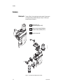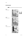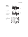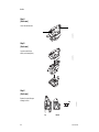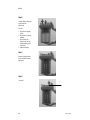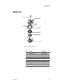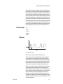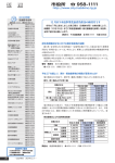
1
GE Healthcare
Aestiva/5
Operation Manual - Part 2
Software Revision 4.X
Setup, Cleaning, Maintenance, Troubleshooting
User Responsibility
This Product will perform in conformity with the description thereof contained in
this Operation manual and accompanying labels and/or inserts, when
assembled, operated, maintained, and repaired in accordance with the
instructions provided. This Product must be checked periodically. A defective
Product should not be used. Parts that are broken, missing, plainly worn,
distorted, or contaminated should be replaced immediately. Should repair or
replacement become necessary, Datex-Ohmeda recommends that a telephonic
or written request for service advice be made to the nearest Datex-Ohmeda
Customer Service Center. This Product or any of its parts should not be repaired
other than in accordance with written instructions provided by Datex-Ohmeda
and by Datex-Ohmeda trained personnel. The Product must not be altered
without the prior written approval of Datex-Ohmeda. The user of this Product
shall have the sole responsibility for any malfunction which results from
improper use, faulty maintenance, improper repair, damage, or alteration by
anyone other than Datex-Ohmeda.
w CAUTION
U.S. Federal law restricts this device to sale by or on the order of a
licensed medical practitioner. Outside the U.S.A., check local laws
for any restriction that may apply.
Datex-Ohmeda products have unit serial numbers with coded logic which
indicates a product group code, the year of manufacture, and a sequential unit
number for identification.
AAA F 12345
This alpha character indicates the year of product
manufacture and when the serial number was assigned;
“D” = 2000, “E” = 2001, “F” = 2002, etc. “I” and “O” are
not used.
Aestiva, S/5, PSVPro, Tec 5, Tec 6 and Tec 7 are registered trademarks of
Datex-Ohmeda Inc.
Other brand names or product names used in this manual are trademarks or
registered trademarks of their respective holders.
Table of Contents
1/Introduction
How to use this manual . . . . . . . . . . . . . . . . . . . . . . . . . . . . . . . . . . . . . . . . . 1-2
i
Symbols used in the manual or on the equipment . . . . . . . . . . . . . . . . . . . . 1-3
Maintenance summary and schedule . . . . . . . . . . . . . . . . . . . . . . . . . . . . . . 1-6
Operator maintenance . . . . . . . . . . . . . . . . . . . . . . . . . . . . . . . . . . . . . . 1-6
Datex-Ohmeda approved service . . . . . . . . . . . . . . . . . . . . . . . . . . . . . . 1-7
2/Cleaning and Sterilization
Summary . . . . . . . . . . . . . . . . . . . . . . . . . . . . . . . . . . . . . . . . . . . . . . . . . . . . . 2-2
Patient path . . . . . . . . . . . . . . . . . . . . . . . . . . . . . . . . . . . . . . . . . . . . . . . 2-2
Scavenging path . . . . . . . . . . . . . . . . . . . . . . . . . . . . . . . . . . . . . . . . . . . 2-3
Clean and sterilize . . . . . . . . . . . . . . . . . . . . . . . . . . . . . . . . . . . . . . . . . . . . . . 2-4
To wash (by hand or machine) . . . . . . . . . . . . . . . . . . . . . . . . . . . . . . . . 2-4
Autoclave . . . . . . . . . . . . . . . . . . . . . . . . . . . . . . . . . . . . . . . . . . . . . . . . . 2-5
Special requirements . . . . . . . . . . . . . . . . . . . . . . . . . . . . . . . . . . . . . . . 2-6
Assemble . . . . . . . . . . . . . . . . . . . . . . . . . . . . . . . . . . . . . . . . . . . . . . . . . 2-6
Disassemble the patient path . . . . . . . . . . . . . . . . . . . . . . . . . . . . . . . . . . . . 2-7
Canister disassembly . . . . . . . . . . . . . . . . . . . . . . . . . . . . . . . . . . . . . . . . . .2-10
Disassemble the scavenging path . . . . . . . . . . . . . . . . . . . . . . . . . . . . . . . .2-12
How to clean and disinfect the flow sensors . . . . . . . . . . . . . . . . . . . . . . . .2-13
How to clean and sterilize the optional CO2 bypass assembly . . . . . . . . .2-15
3/Setup and Connections
Breathing system setup . . . . . . . . . . . . . . . . . . . . . . . . . . . . . . . . . . . . . . . . . 3-2
Canister setup . . . . . . . . . . . . . . . . . . . . . . . . . . . . . . . . . . . . . . . . . . . . . . . . . 3-6
Pneumatic and electrical connections . . . . . . . . . . . . . . . . . . . . . . . . . . . . . 3-8
How to install gas cylinders (high-pressure leak test) . . . . . . . . . . . . . . . .3-11
Cylinder yokes . . . . . . . . . . . . . . . . . . . . . . . . . . . . . . . . . . . . . . . . . . . .3-11
DIN connections . . . . . . . . . . . . . . . . . . . . . . . . . . . . . . . . . . . . . . . . . .3-12
How to install the gooseneck lamp (12 V) . . . . . . . . . . . . . . . . . . . . . . . . . .3-14
How to attach equipment to the top shelves . . . . . . . . . . . . . . . . . . . . . . .3-15
How to install equipment on the foldout shelf . . . . . . . . . . . . . . . . . . . . . .3-17
Installation notes . . . . . . . . . . . . . . . . . . . . . . . . . . . . . . . . . . . . . . . . . . . . .3-18
1006-0939-000
i
Aestiva
4/User Maintenance
ii
Repair policy . . . . . . . . . . . . . . . . . . . . . . . . . . . . . . . . . . . . . . . . . . . . . . . . . .4-2
Manifold maintenance . . . . . . . . . . . . . . . . . . . . . . . . . . . . . . . . . . . . . . . . . .4-3
Expiratory valve maintenance . . . . . . . . . . . . . . . . . . . . . . . . . . . . . . . . . . . . .4-6
Receiver maintenance (active gas scavenging only) . . . . . . . . . . . . . . . . . .4-8
Flow sensor maintenance . . . . . . . . . . . . . . . . . . . . . . . . . . . . . . . . . . . . . . . .4-9
Breathing circuit maintenance . . . . . . . . . . . . . . . . . . . . . . . . . . . . . . . . . . 4-10
Bellows maintenance . . . . . . . . . . . . . . . . . . . . . . . . . . . . . . . . . . . . . . . . . 4-12
Bellows tests . . . . . . . . . . . . . . . . . . . . . . . . . . . . . . . . . . . . . . . . . . . . . . . . 4-15
O2 sensor calibration - 21% O2 . . . . . . . . . . . . . . . . . . . . . . . . . . . . . . . . . 4-18
O2 sensor calibration - 100% O2 . . . . . . . . . . . . . . . . . . . . . . . . . . . . . . . . 4-21
Flow sensor calibration . . . . . . . . . . . . . . . . . . . . . . . . . . . . . . . . . . . . . . . . 4-24
How to prevent water build-up . . . . . . . . . . . . . . . . . . . . . . . . . . . . . . . . . . 4-25
5/Alarms and Troubleshooting
About alarms . . . . . . . . . . . . . . . . . . . . . . . . . . . . . . . . . . . . . . . . . . . . . . . . . .5-2
Alphabetical list . . . . . . . . . . . . . . . . . . . . . . . . . . . . . . . . . . . . . . . . . . . . . . . .5-4
Breathing system problems (no alarm) . . . . . . . . . . . . . . . . . . . . . . . . . . . 5-15
Electrical problems (power failure, etc.) . . . . . . . . . . . . . . . . . . . . . . . . . . 5-16
Pneumatic problems . . . . . . . . . . . . . . . . . . . . . . . . . . . . . . . . . . . . . . . . . . 5-18
6/Illustrated Parts
Breathing system parts . . . . . . . . . . . . . . . . . . . . . . . . . . . . . . . . . . . . . . . . . .6-2
Top level . . . . . . . . . . . . . . . . . . . . . . . . . . . . . . . . . . . . . . . . . . . . . . . . . .6-2
Main manifold . . . . . . . . . . . . . . . . . . . . . . . . . . . . . . . . . . . . . . . . . . . . . . . . .6-5
Exhalation valve . . . . . . . . . . . . . . . . . . . . . . . . . . . . . . . . . . . . . . . . . . . . . . . .6-7
Bellows . . . . . . . . . . . . . . . . . . . . . . . . . . . . . . . . . . . . . . . . . . . . . . . . . . . . . . .6-9
Test tools and system parts . . . . . . . . . . . . . . . . . . . . . . . . . . . . . . . . . . . . 6-10
7/Theory of Operation and Specifications
Ventilator Theory . . . . . . . . . . . . . . . . . . . . . . . . . . . . . . . . . . . . . . . . . . . . . . .7-2
Modes . . . . . . . . . . . . . . . . . . . . . . . . . . . . . . . . . . . . . . . . . . . . . . . . . . . .7-3
ii
1006-0939-000
Table of Contents
Breathing system schematic . . . . . . . . . . . . . . . . . . . . . . . . . . . . . . . . . 7-7
iii
Electrical block diagram . . . . . . . . . . . . . . . . . . . . . . . . . . . . . . . . . . . . . 7-8
Pneumatic circuits . . . . . . . . . . . . . . . . . . . . . . . . . . . . . . . . . . . . . . . . . . . . . 7-9
Suction regulators (optional) . . . . . . . . . . . . . . . . . . . . . . . . . . . . . . . . . . . .7-12
O2 flowmeter (optional). . . . . . . . . . . . . . . . . . . . . . . . . . . . . . . . . . . . . . . . .7-12
Breathing system . . . . . . . . . . . . . . . . . . . . . . . . . . . . . . . . . . . . . . . . . . . . . .7-13
Breathing system specifications . . . . . . . . . . . . . . . . . . . . . . . . . . . . . . . . .7-15
Pneumatic specifications . . . . . . . . . . . . . . . . . . . . . . . . . . . . . . . . . . . . . . .7-17
Flow specifications . . . . . . . . . . . . . . . . . . . . . . . . . . . . . . . . . . . . . . . . . . . .7-18
Electrical power . . . . . . . . . . . . . . . . . . . . . . . . . . . . . . . . . . . . . . . . . . . . . . .7-19
Power cord . . . . . . . . . . . . . . . . . . . . . . . . . . . . . . . . . . . . . . . . . . . . . . .7-20
Electrical fuses . . . . . . . . . . . . . . . . . . . . . . . . . . . . . . . . . . . . . . . . . . .7-20
Battery information . . . . . . . . . . . . . . . . . . . . . . . . . . . . . . . . . . . . . . . .7-20
Electro-magnetic compatibility . . . . . . . . . . . . . . . . . . . . . . . . . . . . . .7-20
Physical specifications . . . . . . . . . . . . . . . . . . . . . . . . . . . . . . . . . . . . . . . . .7-21
Environmental requirements . . . . . . . . . . . . . . . . . . . . . . . . . . . . . . . . . . . .7-22
Ventilation operating specifications. . . . . . . . . . . . . . . . . . . . . . . . . . . . . . .7-23
Aestiva ventilator accuracy data . . . . . . . . . . . . . . . . . . . . . . . . . . . . . . . . .7-25
Index
Warranty
1006-0939-000
iii
Aestiva
iv
iv
1006-0939-000
1 Introduction
In this section
1-1
How to use this manual . . . . . . . . . . . . . . . . . . . . . . . . . . . . . . . . . . . . . . . . . . . . . . . . . 1-2
Symbols used in the manual or on the equipment . . . . . . . . . . . . . . . . . . . . . . . . . . . 1-3
Maintenance summary and schedule . . . . . . . . . . . . . . . . . . . . . . . . . . . . . . . . . . . . . . 1-6
1006-0939-000
1-1
Aestiva
How to use this manual
This is part two of the Aestiva operation and maintenance manual. It tells you
how to:
• Remove and clean parts
• Set up the system
• Identify and replace worn or damaged parts
• Calibrate the O 2 sensor
The second half of this section is a maintenance schedule.
The last section, troubleshooting, tells you what causes each alarm and what
you can do about it.
Use this manual together with Part 1, which includes the operating
instructions and preoperative checkout.
w WARNING
1-2
If an alarm occurs, safeguard the patient first, before
troubleshooting or repair procedures.
1006-0939-000
1 Introduction
Symbols used in the manual or on the equipment
wWarnings and wCautions tell you about dangerous conditions that can
occur if you do not follow all instructions in this manual.
1-3
Warnings tell about a condition that can cause injury to the operator or the
patient.
Cautions tell about a condition that can cause damage to the equipment. Read
and follow all warnings and cautions.
Other symbols replace words on the equipment or in Datex-Ohmeda manuals.
No one device or manual uses all of the symbols. These symbols include:
On (power)
Off (power)
Standby
Standby or preparatory state for part of
the equipment
“ON” only for part of the equipment
“OFF” only for part of the equipment
Direct current
~
Alternating current
x
Protective earth ground
r
1006-0939-000
Í
m
µ
H
w
wW
N
N
l
O
o
q
p
œ
†
Not autoclavable
Type B equipment
Type BF equipment
Type CF equipment
Caution, ISO 7000-0434
Attention, refer to product
instructions, IEC 601-1
This way up
Dangerous Voltage
y
Earth ground
Electrical input
Electrical output
Pneumatic inlet
Pneumatic outlet
Frame or chassis ground
REF
Stock Number
1-3
Aestiva
å
Y
Alarm silence button
SN
Serial Number
Equipotential
Systems with this mark agree with
the European Council Directive
(93/42/EEC) for Medical Devices
when they are used as specified in
their Operation and Maintenance
Manuals. The xxxx is the
certification number of the
Notified Body used by DatexOhmeda’s Quality Systems.
t
Variability
Read top of float
T
Variability in steps
Vacuum inlet
+
Plus, positive polarity
Suction bottle outlet
P
Minus, negative polarity
Lamp, lighting, illumination
Cylinder
N
Movement in one direction
Isolation transformer
ˆ
Movement in two directions
Linkage system
z
Lock
Risk of Explosion
Z
Unlock
Low pressure leak test
1-4
O2 +
O2 Flush button
1006-0939-000
1 Introduction
134°C
R
u
q
t
Autoclavable
Bag position/ manual ventilation
Open drain (remove liquid)
Inspiratory flow
r
U
Q
1-5
Mechanical ventilation
Close drain
Expiratory flow
O2 sensor connection
End case
The primary regulator is set to pressure
less than 345 kPa.
The primary regulator is set to
pressure less than 414 kPa.
European Union Representative
1006-0939-000
1-5
Aestiva
Maintenance summary and schedule
These schedules show the minimum frequency. You will have to service the
equipment more frequently if you use it:
• In unusual conditions (dirty gas supplies, high temperature, high humidity,
etc.).
• More frequently than normal.
Operator maintenance
Examine all components and do the maintenance procedures more frequently
if necessary.
Minimum
Frequency
Maintenance
Daily
• Clean the external surfaces.
• 21% O2 calibration (circuit O2 sensor).
• Flow sensor calibration
Two weeks
• Drain the vaporizers and discard the agent. This is not
necessary for Tec 6 vaporizers.
Monthly
• 100% O2 calibration (cIrcuit O2 sensor).
• Put Krytox (or a lubricant approved for use with 100%
O2) on all tee handle threads.
During cleaning • Inspect the parts for damage. Replace or repair as
and setup
necessary
Annually
• Replace the external o-rings on the vaporizer ports.
As necessary
•
•
•
•
•
Install new cylinder gaskets on cylinder yokes.
Replace the absorbent in the absorber.
Drain the breathing system.
Drain the breathing circuit module.1
Drain the overflow trap on the optional suction
regulator.
• Replace the circuit O2 sensor.
• Replace the disposable flow sensors (plastic) 2
• Replace the autoclavable flow sensors (metal)3.
• Replace the receiver filter (active gas scavenging only).
1. This is included in the preoperative test procedure.
2. Under typical use the sensor meets specifications for 3 months
3. Under typical use the sensor meets specifications for 1 year.
1-6
1006-0939-000
1 Introduction
Datex-Ohmeda approved
service
Minimum
Frequency
6 months
1006-0939-000
1-7
Maintenance
Have an approved service person do the service tests
and scheduled service maintenance.
1-7
Aestiva
1-8
1006-0939-000
2 Cleaning and Sterilization
2-1
w WARNING Obey applicable safety precautions:
• During the cleaning of the liquid collecting tray, avoid skin or eye contact with
the contents of the absorber. In the event of skin or eye contact, immediately
rinse the affected area with water and seek medical assistance.
• Read the material data sheet for each cleaning agent.
• Read the operation and maintenance manual for all sterilization equipment.
• Wear gloves and safety glasses. A damaged O2 sensor can leak and cause
burns (contains potassium hydroxide).
• Do not breathe the fumes.
w CAUTION To prevent damage:
• Refer to the manufacturer’s data if you have questions about a cleaning agent.
• Do not use organic, halogenated, or petroleum based solvents, anesthetic
agents, glass cleaners, acetone, or other harsh cleaning agents.
• Do not use abrasive cleaning agents (such as steel wool, silver polish or
cleanser).
• Keep all electronic parts away from liquids.
• Do not permit liquid to go into the equipment housings.
• Do not soak synthetic rubber parts for more than 15 minutes. Swelling or faster
aging can occur.
• Only autoclave parts that are marked 134°C.
In this section
Summary . . . . . . . . . . . . . . . . . . . . . . . . . . . . . . . . . . . . . . . . . . . . . . . . . . . . . . . . . . . . 2-2
Clean and sterilize . . . . . . . . . . . . . . . . . . . . . . . . . . . . . . . . . . . . . . . . . . . . . . . . . . . . . 2-4
Disassemble the patient path . . . . . . . . . . . . . . . . . . . . . . . . . . . . . . . . . . . . . . . . . . . . 2-7
Canister disassembly . . . . . . . . . . . . . . . . . . . . . . . . . . . . . . . . . . . . . . . . . . . . . . . . . . 2-10
Disassemble the scavenging path . . . . . . . . . . . . . . . . . . . . . . . . . . . . . . . . . . . . . . . 2-12
How to clean and disinfect the flow sensors . . . . . . . . . . . . . . . . . . . . . . . . . . . . . . . 2-13
How to clean and sterilize the optional CO2 bypass assembly . . . . . . . . . . . . . . . . . 2-15
1006-0939-000
2-1
Aestiva
Summary
Patient path
The parts in Figure 2-1 send exhaled gas back to the patient. They may require
more frequent cleaning/sterilization than parts in Figure 2-2. Refer to your
hospital’s infection control policy.
Autoclave (134°C) or
wash (mild detergent pH <10.5)
AB.23.003
2-2
*
If plastic, refer to cleaning/disinfection
procedure. If metal, autoclave (134°C)
AB.23.079
Wipe with a damp cloth.
*
Figure 2-1 • These parts return exhaled gas to the patient
2-2
1006-0939-000
2 Cleaning and Sterilization
2-3
Autoclave (134°C) or
wash (mild detergent pH <10.5)
AB.23.080
AB.23.003
Scavenging path
Figure 2-2 • These parts do not send gas back to the patient
1006-0939-000
2-3
Aestiva
Clean and sterilize
The Disassembly part of this section tells you how to remove parts for
cleaning.
2-4
To wash (by hand or
machine)
AB.23.085
Patient path
AB.23.083
Scavenging path
Use a mild detergent (pH <10.5). Then, rinse and dry completely. All parts
except the O2 sensor, and flow sensors can be washed.
User maintenance tells you how to disassemble parts and clean inside them if
necessary.
2-4
1006-0939-000
2 Cleaning and Sterilization
Autoclave
Patient path
2-5
AB.23.087
Metal Only
AB.23.086
Upside down
AB.23.083
Scavenging path
Autoclave at 134°C. Inspect the parts for deterioration. The User Maintenance
section tells you how to do this.
1006-0939-000
2-5
Aestiva
Special requirements
*
AB.23.088
2-6
* Hang the bellows upside down
(extended) to dry. If not, the
convolutions can stick together.
• To clean the circuit O2 sensor, wipe it with a damp cloth. Do not put the sensor
in liquid.
• To clean/disinfect metal/or plastic flow sensors, use the flow sensor
cleaning procedure. Do not get the connectors wet.
• Disassemble the bellows before you wash it. If not, it will take a very long time
to dry. Hang the bellows upside down to dry.
• Assemble the bellows before you autoclave. Autoclave the bellows upside
down.
w WARNING
Do not use talc, zinc stearate, calcium carbonate, corn starch or
equivalent materials to prevent tackiness. These materials can go
into the patient’s lungs and airways and cause irritation or injury.
w CAUTION
Do not put the circuit O2 sensor or flow sensor connector in liquid.
w
Do not autoclave the Circuit O2 sensor or the plastic flow sensors.
w
Do not clean the interior surfaces of the flow sensors. Use a damp
cloth on external surfaces only.
Assemble
The Setup section tells you how to assemble the breathing system.
Inspect all parts for deterioration. Replace them if necessary.
The Preoperative tests in Part 1 (the first half of this manual), tell you how to
test the system for correct operation.
2-6
1006-0939-000
2 Cleaning and Sterilization
Disassemble the patient path
2-7
Step 1
AA.96p.009
Open the access panel.
Step 2
AA.96p.010
Push up on the latch located under the
flow sensor module.
Step 3
AA.96p.011
Remove the flow sensor module. You
will feel some resistance. Continue to
pull.
Step 4
AA.96p013, 014
Disconnect the cable and remove the
O2 sensor.
1006-0939-000
2-7
Aestiva
Step 5
Completely loosen the thumbscrew on
the breathing circuit module.
AA.96p016
2-8
Step 6
AA.96p017
Remove the module. You will feel some
resistance. Continue to pull.
Step 7
AA.96p018
Push the metal button to the first stop.
Pull out the bag arm.
Step 8
AA.96p020
Push the metal button to the
second stop and open the top panel.
2-8
1006-0939-000
2 Cleaning and Sterilization
Step 9
Push the release button and remove
the bellows assembly (pull up).
AA.96p021, 23
2-9
Step 10
AA.96p024
Remove the main manifold.
Autoclave assemblies marked 134°C. Refer to the Section “Clean and
sterilize” for complete instructions. To assemble the circuit refer to the Setup
section.
1006-0939-000
2-9
Aestiva
Canister disassembly
w CAUTION
2-10
To prevent damage, pull the release handle forward. Then turn the handle
Step 1
AA.96p026
Pull the release forward.
wZ
Step 2
AA.96p028
Turn the release clockwise.
Step 3
AA.96p029
Pull down and out on the canisters.
2-10
1006-0939-000
2 Cleaning and Sterilization
Step 4
Push in the buttons on each side of the
top dish.
AA.96p053
2-11
Step 5
Lift up the drain dish.
AA.96p054
Remove the top dish and drain dish.
Continue with the next section or go to "Clean and sterilize". To assemble,
refer to the Setup section.
1006-0939-000
2-11
Aestiva
Disassemble the scavenging path
These parts send exhaled gas to the disposal system, not the patient.
Exhalation valve
Complete the basic disassembly
procedure.
AB.23.089
Push in the latches and pull out the
exhalation valve.
Scavenging reservoir
Loosen the knob and remove the rear
cover.
Pull the reservoir up and to the rear.
Twist and pull down to remove the tube.
AB.23.090
2-12
2-12
1006-0939-000
2 Cleaning and Sterilization
How to clean and disinfect the flow sensors
wCAUTION
Do not autoclave plastic flow sensors.
2-13
w
Do not use high-pressure gas, or brushes to clean the flow sensors.
w
Do not use cleaning solvents that are not approved for use with
Polycarbonates (e.g. CIDEX Plus).
CIDEX sterilization
Both Datex-Ohmeda and the manufacturer of CIDEX (Johnson & Johnson)
have tested this procedure.
• CIDEX must be 14 day mixture, with activator vial REF REORDER # 2245
• One liter of this solution cleans four (4) flow sensors
Procedure (Figure 2-3)
1. Remove the flow sensor module from the absorber. Refer to “Disassemble
the patient path” in this section.
2. Remove the flow sensors from the module.
• Push in the latch.
• Pull off the cover.
• Remove the flow sensors.
3. Submerge the flow sensor and tubes in activated CIDEX solution. Keep the
connector dry.
4. Keep the solution in the tubes for the sterilization period.
5. Submerge the flow sensor and tubes in distilled water. Again, do not get the
connector wet.
6. Rinse as indicated in CIDEX instructions.
7. Do steps 5 and 6 again to remove all CIDEX.
8. COMPLETELY dry the flow sensor and the tubes before you use the sensor.
Use a dry syringe, or connect vacuum or pressure to remove all liquid from the
sensor (sensor, tubes, and connector):
• Minimum time: 1 min
• Maximum vacuum: 30 in Hg
• Maximum flow: 10 L/min flow
• Maximum pressure: 345 kPa (50 psi).
1006-0939-000
2-13
Aestiva
2-14
Step 2
Steps 3 and 4
Steps 5, 6 and 7
Step 8
Dry for > 1 min with these precautions:
• Maximum vacuum 30 in Hg
• Maximum flow 10 L/min
• Maximum pressure 345 kPa (50 psi)
Figure 2-3 • Steps 2-8
2-14
1006-0939-000
2 Cleaning and Sterilization
How to clean and sterilize the optional CO2 bypass assembly
These instructions assume that the system has the optional CO 2 bypass
feature installed.
2-15
Step 1
Remove the absorber canisters. (Also described in “Canister disassembly” in this section.)
a. Pull the canister release handle forward.
w CAUTION
To prevent damage, pull the canister release handle forward before turning the
handle.
b. Turn the release handle clockwise.
c. Lift out the canisters.
Note: The canisters should drop under their own weight when released. If they do not, clean and lubricate the pins in
the drain dish and sockets in the base.
Step 2
Release the CO2 bypass assembly by
pushing both buttons (one on each side
of the assembly).
Step 3
Pull down on the CO2 bypass assembly
(a) to remove it and lift the drain dish
(b) up.
a
b
1006-0939-000
2-15
Aestiva
Step 4
2-16
Clean and sterilize the bypass
assembly:
a. Immerse the assembly into a
solution of mild detergent and
water.
b. Agitate the assembly in the
solution while repeatedly
actuating and releasing the
plate.
c. Rinse the assembly by
immersing it in clean water and
agitating it again with the plate
actuated and released.
d. Autoclave the assembly at
134°C.
e. Cool about 40 minutes at room
temperature.
a
Note: Optionally, the bypass assembly can be divided into two smaller sections for easier cleaning by releasing the
top clamp (a) and pulling the hose from the assembly. When reassembling, reattach the hose to the bottom part of the
assembly. Secure the hose with the clamp and pinch the clamp one notch past finger-tight with pliers.
Step 5
Reinstall the bypass assembly:
a. Reinstall the drain dish.
b. Insert the bypass assembly.
c. Push back and adjust to locate
the access holes for the top
ports.
d. Push the buttons on each side of
the assembly and push the
assembly up; both buttons
should snap into place.
e. Pull down on the assembly to
make sure it is locked into place.
2-16
c
d
b
a
1006-0939-000
2 Cleaning and Sterilization
Step 6
Reinstall the canisters:
a. Ensure seals and rim are free of soda lime dust.
b. Place the canisters in the drain dish.
c. Turn the canister release handle counterclockwise to its locked position while gently applying pressure on the
canisters to hold them against the canister guides.
Step 7
Test the Bag circuit for leaks according to the Breathing System tests in the Appendix section of Part 1 of the Operation
manual.
• Do the test in both the Absorber mode and the Bypass mode.
• Ensure the alarm message “No CO2 Absorption” activates when in Bypass mode. See “CO2 Bypass mode operation”
in section 3 of Part 1 of the Operation manual.
Step 8
Before you use the system, complete the Preoperative Test procedure. Refer to the ‘Appendix - Preoperative Tests’
section of the Operation Manual Part 1, System Controls, Operation and Checkout.
1006-0939-000
2-17
2-17
Aestiva
2-18
2-18
1006-0939-000
3 Setup and Connections
Important
Important
Important
Datex-Ohmeda strongly recommends that you use O2 monitoring with this equipment.
Refer to local standards for mandatory monitoring.
European Standard EN 740 requires anesthetic agent monitoring when anesthetic
vaporizers are in use.
European Standard EN 740 requires CO2 monitoring during ventilation.
w WARNINGS Always make sure that the pipeline supply hoses and the breathing circuit
components are not toxic and will not:
• Cause an allergic reaction in the patient.
• React with the anesthetic gases or agent to produce dangerous
by-products.
w To prevent incorrect values or equipment malfunction, use only
Datex-Ohmeda cables, hoses and tubing.
w This system operates correctly at the electrical interference levels of IEC
601-1-2. Higher levels can cause nuisance alarms that may stop
mechanical ventilation.
w To help prevent false alarms from devices with high-intensity electrical
fields:
• Keep the electrosurgical leads away from the breathing system and the
flow and oxygen sensors.
• Do not put the electrosurgical leads on any part of the anesthesia system.
w To protect the patient when electrosurgical equipment is used:
• Monitor the correct operation of all life support and monitoring equipment.
• Keep backup manual ventilation available in case the electrosurgical
equipment prevents safe use of the ventilator.
• Do not use conductive masks or hoses.
In this section
Breathing system setup . . . . . . . . . . . . . . . . . . . . . . . . . . . . . . . . . . . . . . . . . . . . . . . . 3-2
Canister setup . . . . . . . . . . . . . . . . . . . . . . . . . . . . . . . . . . . . . . . . . . . . . . . . . . . . . . . . 3-6
Pneumatic and electrical connections . . . . . . . . . . . . . . . . . . . . . . . . . . . . . . . . . . . . 3-8
How to install gas cylinders (high-pressure leak test) . . . . . . . . . . . . . . . . . . . . . . .3-11
How to attach equipment to the top shelves . . . . . . . . . . . . . . . . . . . . . . . . . . . . . .3-15
How to install equipment on the foldout shelf . . . . . . . . . . . . . . . . . . . . . . . . . . . . .3-17
Installation notes . . . . . . . . . . . . . . . . . . . . . . . . . . . . . . . . . . . . . . . . . . . . . . . . . . . .3-18
1006-0939-000
3-1
3-1
Aestiva
Breathing system setup
To assemble the patient circuit, start at step 5.
Install the main manifold.
Step 2
AA.96p022
Install the Bellows.
• Make sure the release
button aligns correctly.
Step 3
AA.96p012
Gently close the control
panel.
Step 4
Install the bag arm.
• Install a rebreathing bag
on the bag arm.
3-2
AA.96p019
3-2
AA.96p024
Step 1
1006-0939-000
3 Setup and Connections
Step 5
Look at the tabs on the rear or
the label on the front.
AB.23.211
Identify the breathing circuit
module (Circle or Mapleson).
Circle
Mapleson
3-3
Step 6
AA.96p017
Install the breathing circuit
module. You will feel some
resistance. Continue to push.
Step 7
AA.96p016
Completely tighten the
thumbscrew.
Install the O2 sensor.
• Completely tighten the
sensor.
• Connect the cable.
1006-0939-000
AA.96p013, 014
Step 8
3-3
Aestiva
Step 9
AA.96p011
Step 10
Close the front panel.
AA.96p009
Step 11
Circle Module
AB.23.104
Connect the patient circuit.
Mapleson D / Bain Module
To-fro
AB.23.152
3-4
Install the flow sensor
module.
• You will hear a “click”
when it locks into
position.
• Refer to Note 1 or the User
Maintenance
section.
3-4
1006-0939-000
3 Setup and Connections
Note 1
Flow sensor assembly
AA.96p038
AA.96p039
3-5
1006-0939-000
3-5
Aestiva
Canister setup
Each canister holds 1.35 kg of loose absorbent or 1.13 kg of commercially
packaged (pre-pack) absorbent. Datex-Ohmeda recommends Sodium or Barium hydroxide based absorbent.
3-6
w WARNING Change absorbent often to prevent the build up of non-metabolic gases
when the system is not in use.
Inspect absorbent at the end of a case. During non-use, absorbent can go
back to the original appearance. Refer to the absorbent labeling for more
information about color changes.
If the absorbent completely dries out, it may give off CO (carbon monoxide)
the next time you use it. For safety, replace the absorbent.
Step 1
AB.23.061
Pull the release forward.
Step 2
AB.23.061
Turn the release clockwise.
3-6
1006-0939-000
3 Setup and Connections
Step 3
Pull down to make sure the top
dish is locked in place.
AA.96p054
Push in the buttons and install
the top dish and drain dish.
3-7
Fill the canisters with absorbent
and install them. Push down on
the drain dish if necessary.
AA.96p029
Step 4
Step 5
AA.96p028
Turn the release
counter-clockwise.
Step 6
AA.96p026
Push in the release.
1006-0939-000
3-7
Aestiva
Pneumatic and electrical connections
wWARNING Equipment connected to the electrical outlets can increase the leakage
current. Regularly test the leakage current.
3-8
wCAUTION Use only medical grade gas supplies. Other types of gas supplies may
contain water, oil, or other contaminants.
The Aestiva gas supplies also supply these devices through internal connections:
• The venturi suction regulator (optional)
• The external O2 flowmeter (optional)
• Ventilator drive gas
• Pneumatic outlets
AA.96.116
Mains inlet
Labels show outlet voltage
ratings and circuit breaker
amp ratings.
AA.96.116
Outlets
AA.96.095
Tec 6 power
3-8
1006-0939-000
3 Setup and Connections
Pipeline inlets
AA.96.116
Label identifies the gas.
3-9
Pneumatic outlet
AA.96.116
Labels identify the gas.
Note: The outlet pressures
range from pipeline pressure
to 550-690 kPa when
cylinder supplies are used.
Adapters may be necessary.
Refer to the Illustrated Parts
section.
1006-0939-000
AA.96.137
Scavenging
3-9
Aestiva
Suction regulator
Optional item.
External vacuum
(non-venturi)
Filter
AA.96.172
Patient
Collection Bottle
External O2 flowmeter
AA.96.045
Optional item.
Serial port
Refer to the communications
appendix for command and
data formats.
3-10
AA.96.116
3-10
Note: Venturi regulators use
the system Air or O2 supply.
Standard regulators must be
connected to an external
vacuum supply.
1006-0939-000
3 Setup and Connections
How to install gas cylinders (high-pressure leak test)
1. Find the cylinder wrench.
AA.96.123
Cylinder yokes
3-11
AA.96.122
2. Close the cylinder valve on the cylinder to be replaced.
AA.96.124
3. Fully loosen the tee handle.
AA.96.125
4. Open the cylinder yoke.
AA.96.126
5. Remove the used cylinder and the used gasket.
6. Remove the cap from the cylinder valve on the new cylinder.
7. Point the cylinder valve away from all flammable items and items that can
be damaged by a release of pressure.
8. Quickly open and close the cylinder valve. This removes dirt from the
cylinder outlet.
1006-0939-000
3-11
Aestiva
w CAUTION No gasket or more than one gasket can cause a leak.
9. Install a new gasket.
10.Align the cylinder post with the index pins.
11.Close the yoke gate and tighten the tee handle.
3-12
12.Install a cylinder plug and gasket in all empty cylinder yokes.
13.Do a high-pressure leak test:
• Disconnect pipeline supplies.
• Disconnect all equipment from the pneumatic outlet and turn Off the
auxiliary flowmeter.
• Set the system switch to Standby.
• Open the cylinder.
• Record the cylinder pressure.
• Close the cylinder.
• If the cylinder pressure decreases more than 690 kPa in one minute,
there is a leak.
To repair a leak:
• Install a new cylinder gasket and tighten the tee handle.
• Do this step again. If the leak continues, do not use the system.
w
WARNING
Do not leave gas cylinder valves open if the pipeline supply is in use. Cylinder supplies
could be depleted, leaving an insufficient reserve supply in case of pipeline failure.
1. Close the cylinder valve on the cylinder to be replaced.
AA.96.127
DIN connections
AA.96.129
2. Loosen the adapter and remove the cylinder.
3. Remove the cap from the cylinder valve on the new cylinder.
4. Point the cylinder outlet away from all items that can be damaged by a
release of high-pressure gas.
3-12
1006-0939-000
3 Setup and Connections
5. Open and immediately close the cylinder valve to remove dirt or contaminants.
6. Do a high pressure leak test:
• Disconnect pipeline supplies.
• Disconnect all equipment from the pneumatic outlet and turn Off the
auxiliary flowmeter.
• Set the system switch to Standby.
• Open the cylinder.
• Record the cylinder pressure.
• Close the cylinder.
• If the cylinder pressure decreases more than 690 kPa in one minute,
there is a leak.
To repair a leak:
• Tighten the cylinder connection.
• Do this step again. If the leak continues, do not use the system.
w WARNING Do not leave gas cylinder valves open if the pipeline supply is in use.
Cylinder supplies could be depleted, leaving an insufficient reserve supply
in case of pipeline failure.
1006-0939-000
3-13
3-13
Aestiva
How to install the gooseneck lamp (12 V)
WARNING Use ONLY 2.4 Watt bulbs. Higher wattage bulbs can get hot enough to burn
wW
you.
3-14
AA.96.173
1. Align the connector with the cable towards you.
2. Push the connector firmly into the socket until you hear a click.
3. Move the light into position.
3-14
1006-0939-000
3 Setup and Connections
How to attach equipment to the top shelves
The basic system has two straps for equipment. Accessory shelves use clips
and straps.
w CAUTION Each accessory shelf has a weight limit of 23 kg (50 lb).
3-15
w Systems without accessory shelves have a weight limit of 23 kg (50 lb).
1. Install or find the clips:
AA71.145
• With an accessory shelf, install the clips in the two slots nearest to the
equipment.
AA.96.130
• Systems without accessory shelves have the clips attached.
1006-0939-000
3-15
Aestiva
2. Install the straps:
• With an accessory shelf:
Large equipment.
Loop one time
(A, B, C)
B
A
AA.50.015
3-16
C
A
B
C
Small equipment.
Loop two times
(A, B, C, D)
A
D
B
A
B
C
C
• Without an accessory shelf:
C
AA.96.135
D
B
A
3. Fully tighten the straps.
4. Make sure that the straps hold the equipment in position.
w WARNING If you do not fully tighten the strap, equipment can fall off the shelf.
3-16
1006-0939-000
3 Setup and Connections
How to install equipment on the foldout shelf
This is a hidden shelf for equipment that you do not need to look at, adjust, or
touch. To access the shelf, you must remove the cylinders.
1. Make sure you have a cylinder wrench (if necessary).
2. Close the valves on all gas cylinders.
3-17
AA.96.118
3. Remove all gas cylinders.
AA.96.120
AA.96.119
4. Loosen the thumbscrews and open the rear door.
5. Put the equipment on the shelves.
AA.96.114
6. Make sure the item does not hang over the raised edge.
7. Connect all cables and route them through the cutouts in the door.
8. Close the door.
9. Test the equipment.
10.Install the cylinders.
w WARNING Items that hang over the raised edge can fall off.
1006-0939-000
3-17
Aestiva
Installation notes
When the system is installed the service representative will check these settings and change them if necessary.
WARNING These settings can only be changed by Qualified Service personnel.
wW
3-18
• Language
• Power up defaults: When you turn the system off, should it save the current
settings or go back to the facility defaults.
• Automatic calculation of ◊E alarm limits during mechanical ventilation.
• Altitude
• Ventilator drive gas
• Heliox mode availability
3-18
1006-0939-000
4 User Maintenance
w WARNING
TO PREVENT FIRES:
4-1
1
• Use lubricants approved for anesthesia or O2 equipment, such as Krytox® .
• Do not use lubricants that contain oil or grease. They burn or explode
in high O2 concentrations.
• All covers used on the system must be made from antistatic (conductive)
materials. Static electricity can cause fires.
w WARNING
In this section
Obey infection control and safety procedures. Used equipment may
contain blood and body fluids.
Repair policy . . . . . . . . . . . . . . . . . . . . . . . . . . . . . . . . . . . . . . . . . . . . . . . . . . . . . . . . 4-2
Manifold maintenance . . . . . . . . . . . . . . . . . . . . . . . . . . . . . . . . . . . . . . . . . . . . . . . . 4-3
Expiratory valve maintenance . . . . . . . . . . . . . . . . . . . . . . . . . . . . . . . . . . . . . . . . . . 4-6
Receiver maintenance (active gas scavenging only) . . . . . . . . . . . . . . . . . . . . . . . . 4-8
Flow sensor maintenance . . . . . . . . . . . . . . . . . . . . . . . . . . . . . . . . . . . . . . . . . . . . . 4-9
Breathing circuit maintenance . . . . . . . . . . . . . . . . . . . . . . . . . . . . . . . . . . . . . . . . 4-10
Bellows maintenance . . . . . . . . . . . . . . . . . . . . . . . . . . . . . . . . . . . . . . . . . . . . . . . . 4-12
Bellows tests . . . . . . . . . . . . . . . . . . . . . . . . . . . . . . . . . . . . . . . . . . . . . . . . . . . . . . . 4-15
O2 sensor calibration - 21% O2 . . . . . . . . . . . . . . . . . . . . . . . . . . . . . . . . . . . . . . . . 4-18
O2 sensor calibration - 100% O2 . . . . . . . . . . . . . . . . . . . . . . . . . . . . . . . . . . . . . . . 4-21
Flow sensor calibration . . . . . . . . . . . . . . . . . . . . . . . . . . . . . . . . . . . . . . . . . . . . . . 4-24
How to prevent water build-up . . . . . . . . . . . . . . . . . . . . . . . . . . . . . . . . . . . . . . . . . 4-25
1.
® Krytox is a registered trademark of Dupont de Nemours E.I. & Company Inc
1006-0939-000
4-1
Aestiva
Repair policy
Do not use malfunctioning equipment. Make all necessary repairs or have the
equipment serviced by an authorized Datex-Ohmeda service representative. After repair,
test the equipment to ensure that it is functioning properly, in accordance with the
manufacturer’s published specifications.
To ensure full reliability, have all repairs and service done by an authorized DatexOhmeda service representative. If this cannot be done, replacement and maintenance
of those parts listed in this manual may be undertaken by a competent, trained
individual having experience in the repair of devices of this nature.
4-2
w CAUTION
No repair should ever be attempted by anyone not having experience in the
repair of devices of this nature.
Replace damaged parts with components manufactured or sold by Datex-Ohmeda.
Then test the unit to ascertain that it complies with the manufacturer’s published
specifications.
Contact the Datex-Ohmeda Customer Service Center for service assistance. In all cases,
other than where Datex-Ohmeda’s warranty is applicable, repairs will be made at DatexOhmeda’s current list price for the replacement part(s) plus a reasonable labor charge.
4-2
1006-0939-000
4 User Maintenance
Manifold maintenance
Complete the basic
disassembly (Refer to the
Cleaning and Sterilization
section).
AB.23.094
Step 1
4-3
Remove the diaphragm.
Replace it if:
• The disk, cage, or
diaphragm is damaged.
• The diaphragm looks
worn.
• The diaphragm fits over
the rim.
AB.23.069
Step 2
(APL valve)1
Loosen the thumbscrew and
remove the plate.
• Replace the seal if
damaged or worn.
1006-0939-000
AB.23.070
Step 3
(Seals)
4-3
Aestiva
Step 4
(Seals con.)
AB.23.073
Loosen the thumbscrews.
4-4
Step 5
(Seals con.)
AB.23.074
Open the manifold (top
middle, and bottom parts).
Replace the parts if they are
damaged or worn.
Side
Top
4-4
AB.23.071
Step 6
(Seals con.)
Bottom
1006-0939-000
4 User Maintenance
Step 7
(Bag/Vent)2
Replace the parts if they are
damaged or worn.
AB.23.077
4-5
Step 8
AB.23.075
Put the parts together
• Make sure all gaskets are
fully seated.
• Fully tighten the
thumbscrews.
1. When you turn the APL knob, you change the pressure that is necessary to push the disk up and permit gas
to exit.
2. The Bag/Vent switch pushed down plungers to close the other path. In the Bag position, the vent path is
closed, etc.
Before you use the system, complete the preoperative test procedure. Refer to
"Appendix - Preoperative Tests" section of Part 1 of the Operation Manual.
1006-0939-000
4-5
Aestiva
Expiratory valve maintenance
Disassemble the manifold and examine the seals at 12 autoclave cycles.
These conditions indicate a possible leak in the exhalation valve:
• A decrease in airway pressure during the inspiratory pause in the volume control
mode of ventilation.
• Alarms for low tidal volume.
• The ventilator circuit has a leak, but the bellows pass the bellows tests in this
section.
4-6
Step 1
AB.23.089
Remove the exhalation valve
(Cleaning and Sterilization
section).
Step 2
AB.23.093
Remove the top cover.
4-6
1006-0939-000
4 User Maintenance
Step 3
AB.23.072
Unscrew the lock ring (one
quarter turn) and remove the
cap.
4-7
Step 4
AB.23.021
Put the parts together
• Align the dimples in the
cap with the valve seat.
• To install the top, align it
with the base and push
down.
Dimples
Before you use the system, complete the preoperative test procedure. Refer to
"Appendix - Preoperative Tests" section of Part 1 of the Operation Manual.
1006-0939-000
4-7
Aestiva
Receiver maintenance (active gas scavenging only)
A blocked filter decreases flow through the scavenging system. In extreme cases this can
open the high-pressure relief valve and vent to room air.
Note: Passive gas scavenging does not require maintenance.
Step 1
AB.23.091
Remove the receiver:
• Loosen the thumbscrew.
• Remove the rear cover.
• Pull out and up on the
receiver.
Step 2
Replace the filter (friction fit
with gasket).
AB.23.092
4-8
Filter
w WARNING
This system operates correctly at the electrical interference levels of IEC
601-1-2. Higher levels can cause nuisance alarms that may stop
mechanical ventilation.
• Always make sure that the rear cover is installed.
• Completely tighten the thumbscrew.
Before you use the system, complete the preoperative test procedure. Refer to
"Appendix - Preoperative Tests" section of Part 1 of the Operation Manual.
4-8
1006-0939-000
4 User Maintenance
Flow sensor maintenance
Step 1
4-9
AA.96p.037
Remove the flow sensor
module (Cleaning and
Sterilization section).
Push in the tab and remove
the cover.
Step 2
Keep the tubes straight.
AA.96p.039
Install the new sensor with
the arrows up.
Step 3
AA.96p.038
Slide on the cover. Do not
pinch the tubes.
Before you use the system, complete the preoperative test procedure. Refer to
"Appendix - Preoperative Tests" section of Part 1 of the Operation Manual.
1006-0939-000
4-9
Aestiva
Breathing circuit maintenance
Disassemble the patient circuit module to replace check valves or seals.
Step 1
Remove the patient circuit
module (Cleaning and
Sterilization section).
AA.96p.017
Step 2
AA.96p.041
Hold in the tab.
Step 3
Remove the rear cover.
Note: The rear seal is keyed
to fit a specific module.
4-10
AA.96p.042
4-10
1006-0939-000
4 User Maintenance
Step 4
AA.96p.043
Push in the tabs and remove
the top cover.
4-11
Step 5
AA.96p.045
AA.96p.044
Remove the seals.
Turn and pull to remove the
check valves.
Do the steps in the opposite order to assemble the module.
Before you use the system, complete the preoperative test procedure. Refer to
"Appendix - Preoperative Tests" section of Part 1 of the Operation Manual.
1006-0939-000
4-11
Aestiva
Bellows maintenance
Step 1
Remove the bellows from the
breathing system.
AA.96p.023
4-12
Step 2
AA.96p.051
Turn the housing
counter-clockwise and lift.
Step 3
AA.96p.052
Remove the bottom edge of
the bellows from the rim.
4-12
1006-0939-000
4 User Maintenance
Step 4
AA.96p.031
Remove the disk from the
bellows.
4-13
Step 5
AA.96p.032
Remove the ring from inside
the top of the bellows.
Step 6
AA.96p.033
Push the latch toward the
center and remove the rim.
Step 7
AA.96p.034
Remove the pressure relief
assembly.
w WARNING Do not disassemble the pressure relief valve. This can damage the seat or
diaphragm and cause injury to the patient.
1006-0939-000
4-13
Aestiva
Step 8
AA.96p.035
Push the latch towards the
center and remove the
locking tabs.
4-14
Step 9
AA.96p.036
Remove the seal.
Do these steps in the opposite order to assemble the bellows. If you see a dust-like
powder on the housing or the bellows, apply a thin layer of KRYTOX lubricant to the ribs
of the bellows housing. Make sure the lubricant is applied smoothly and there are no
lumps.
Make sure that:
• The arrow on the seal points up.
• You hear a double click when you install the rim.
• The rim is locked in position.
• The inner ring is correctly installed inside the top of the bellows.
• Only the bottom ring of the bellows fits over the rim.
• The housing is locked in position. You cannot lift it off.
4-14
1006-0939-000
4 User Maintenance
Bellows tests
w WARNING Objects in the breathing system can stop gas flow to the patient. This can
cause injury or death:
•
Do not use a test plug that is small enough to fall into the breathing
system.
• Make sure that there are no test plugs or other objects caught in the
breathing system.
w WARNING
The bellows assembly test does not replace the preoperative tests. Always
complete the tests in the section Preoperative Tests before you use the
system with a patient.
This test makes sure that all components are correctly assembled. It is not an alternative
to a complete system checkout.
If the bellows operates correctly, install it in the system.
If there is a problem, disassemble the bellows. Look for and replace damaged parts.
Step 1
Hold the bellows assembly
vertical and close the
ports (A and B).
A
B
1006-0939-000
4-15
4-15
Aestiva
Step 2
Invert the bellows. They must
not fall more than
100 mL/min.
If it does:
Step 3
Remove the plugs from the
ports. Permit the bellows to
fully extend.
Step 4
Close port C.
C
AA.96p.124
4-16
• The ports are not tightly
sealed.
• The bellows is incorrectly
installed.
• The seal inside the
bellows is not correctly
installed (with its groove
pointed up).
• Parts are damaged.
4-16
1006-0939-000
4 User Maintenance
Step 5
The bellows must not fall
more than 100 mL/min.
If it does:
• The port is not tightly
sealed.
• The bellows or the
pressure relief valve is
not correctly installed.
• Parts are damaged.
4-17
If the result for all the bellows tests was “passed,” install it in the system.
Before you use the system, complete the preoperative test procedure. Refer to
"Appendix - Preoperative Tests" section of Part 1 of the Operation Manual.
1006-0939-000
4-17
Aestiva
O2 sensor calibration - 21% O2
Note: The 21% O2 calibration must be done before the 100% O2 calibration. During O2
calibration the screen replaces O2 data with - - -. Mechanical ventilation must be off to
perform calibration.
This procedure takes three minutes or less.
Step 1
4-18
AB.29.013
Push the menu key.
Step 2
AB29.002
AB.90.036
Turn the knob to select
Setup/Calibration (highlight).
Step 3
AB.90.091
AB.90.037
Push the knob to show the
next screen.
4-18
1006-0939-000
4 User Maintenance
Step 4
AB.29.012
AB.90.048
AB29.002
Turn, then push the knob to
select O2 Sensor Cal.
4-19
Step 5
AB.90.049
Select 21%. Then, push the
knob.
Step 6
Complete the steps shown on
the screen.
• Remove the O2 sensor from
the circuit.
• Do not twist or stress the
cable.
• Make sure the cable is
connected.
Step 7
AB.48.080
Select Start Cal.
Then, push the knob.
The screen shows “Calibrating. . .”, followed by the result (“Complete” or “Failure”).
1006-0939-000
4-19
Aestiva
If the calibration fails:
• perform the calibration again.
• do a 100% O2 sensor calibration. If this passes, repeat the 21% O2 calibration.
If the calibration passes, install the O2 sensor. If necessary, do the 100% O2 calibration.
Before you use the system, complete the preoperative test procedure. Refer to
"Appendix - Preoperative Tests" section of Part 1 of the Operation Manual.
4-20
4-20
1006-0939-000
4 User Maintenance
O2 sensor calibration - 100% O2
Note: If w appears on the screen, the 21% O2 calibration must be completed before the
100% O2 calibration. Mechanical ventilation must be off to perform calibration.
This procedure takes three minutes or less.
Step 1
Push the menu key.
AB.29.003
4-21
Step 2
AB29.002
AB90.036
Turn the knob to select
Setup/Calibration (highlight).
Step 3
AB90.037
Push the knob to show the
next screen.
1006-0939-000
4-21
Aestiva
4-22
AB.29.046
AB90.048
Turn, then push the knob to
select O2 Sensor Cal.
AB29.002
Step 4
Step 5
AB.90.050
Select 100%. Then, push the
knob.
Step 6
AB.90.088
With the O2 sensor in the
circuit, fill the circuit with
100% O2:
• Push the flush button.
• Then flow 100% O2 at
5 L/min. (circuit should
be open).
Step 7
AB48.081
Select Start Cal.
Then, push the knob.
4-22
1006-0939-000
4 User Maintenance
The screen shows “Calibrating . . . ”, followed by the result (“Complete” or “Failure”).
If the calibration fails,
• perform the calibration again.
• decrease the airway pressure, and repeat the calibration.
Before you use the system, complete the preoperative test procedure. Refer to
"Appendix - Preoperative Tests" section of Part 1 of the Operation Manual.
4-23
1006-0939-000
4-23
Aestiva
Flow sensor calibration
Minimum Frequency: Weekly
The system automatically corrects for zero offset when you unplug the flow sensor
connectors with power on. You must stop mechanical ventilation before you calibrate the
flow sensors.
Step 1
4-24
AA.96p.010
Push up on the latch under
the flow sensor module.
Remove the flow sensor
module. You will feel some
resistance. Continue to pull.
Step 2
When calibration is complete,
the screen shows, "No Insp
flow sensor" and "No Exp
flow sensor".
No Insp Flow Sensor
No Exp Flow Sensor
Step 3
• Install the flow sensor
module.
4-24
1006-0939-000
4 User Maintenance
How to prevent water build-up
w WARNING
During the cleaning of the liquid collecting tray, avoid skin or eye contact with the
contents of the absorber. In the event of skin or eye contact, immediately rinse the
affected area with water and seek medical assistance.
Why is water buildup a
problem?
Pooled water in the sensor or water in the sensing lines causes false alarms.
How much water is too
much?
A thin layer of water or a foggy look in the flow sensors is OK. Drops of water is too much.
Where does the water
come from?
Water comes from exhaled gas and a chemical reaction between CO 2 and the soda lime
in the absorber.
4-25
At lower fresh gas flows more water builds up because less gas is scavenged and:
• More CO2 stays in the absorber to react and produce water.
• More moist, exhaled gas stays in the absorber.
Solutions
1006-0939-000
• Drain the absorber each morning.
• Drain all hoses as necessary.
• Flow sensor tubes must point up so that they do not collect water.
• With a circle breathing circuit, push the drain button before every case (listed in
preoperative procedures).
• If Check Flow Sensors alarm occurs during a VERY LONG case, replace the flow
sensors. Allow the original flow sensors to dry before you use them again.
4-25
Aestiva
4-26
4-26
1006-0939-000
5 Alarms and
Troubleshooting
5-1
w CAUTION
In this section
No repair should ever be attempted by anyone not having experience in the
repair of devices of this nature.
About alarms . . . . . . . . . . . . . . . . . . . . . . . . . . . . . . . . . . . . . . . . . . . . . . . . . . . . . . 5-2
Alphabetical list . . . . . . . . . . . . . . . . . . . . . . . . . . . . . . . . . . . . . . . . . . . . . . . . . . . 5-4
Breathing system problems (no alarm) . . . . . . . . . . . . . . . . . . . . . . . . . . . . . . . .5-15
Electrical problems (power failure, etc.) . . . . . . . . . . . . . . . . . . . . . . . . . . . . . . .5-16
Pneumatic problems . . . . . . . . . . . . . . . . . . . . . . . . . . . . . . . . . . . . . . . . . . . . . .5-18
1006-0939-000
5-1
Aestiva
About alarms
w WARNING
If an alarm occurs, safeguard the patient first, before troubleshooting
or repair procedures.
Two areas on the screen show alarms. The area at the top of the display shows
most alarms. If there are more than 4 alarms at the same time, the lower priority
alarms cycle every two seconds.
During severe malfunctions that prevent mechanical ventilation and/or
monitoring, the area under the waveform shows minimum system messages.
During normal operation, this area shows instructions (push the knob, etc.).
5-2
AB.90.025
Alarms
Alarm priority depends on the level of danger to the patient. High priority alarms
require immediate attention.
5-2
Priority
Alarm tone
Alarm silence
Note
High
10 tones,
10 second pause,
repeat
120 seconds or
cannot be silenced
Reverse video
Medium
3 tones,
25 second pause,
repeat
120 seconds
---
Low
Single tone
Tone does not repeat
---
1006-0939-000
5 Alarms and Troubleshooting
Alarm messages have three general causes.
• Malfunctions: Some malfunctions cause reduced function (for example, no
PEEP). Others prevent mechanical ventilation (Minimum shutdown).
• Patient monitoring: These are high and low limit settings that you adjust.
• Informational: Control settings or system conditions can change operation. For
example, if the audible circuit leak alarm is Off, the screen shows “Circuit Leak
Audio Off” as a low priority alarm.
5-3
1006-0939-000
5-3
Aestiva
Alphabetical list
The instructions in this section tell you what you can do:
• During a case to protect the patient
• After the case to repair a problem
This table does not include operator instructions.
There are two special types of alarms:
• Minimum monitoring alarms stop mechanical ventilation.
• Minimum shutdown alarms stop mechanical ventilation and monitoring.
5-4
Message
Priority
+15V Analog Outof-Range
Action/Concerns
Repair
Min. shutdown Ventilator malfunction.
(High)
Ventilate manually.
Monitoring is not reliable.
Contact a qualified
service
representative.
-15V Analog Outof-Range
Min. shutdown Ventilator malfunction.
(High)
Ventilate manually.
Monitoring is not reliable.
Contact a qualified
service
representative.
12 Hour Test
Low
To do the test, move the
system switch from Standby
to On.
Not necessary,
informational.
A/D Converter
Failure
Min. shutdown Ventilator malfunction.
(High)
Ventilate manually.
Monitoring is not reliable.
Contact a qualified
service
representative.
Absorber panel
open
Medium
Close the panel.
---
Adjust Low Ve Limit Medium
Cause
System in use for more
than 12 hours without a
power-up self test.
The top panel is not
completely closed.
Set the low VE alarm.
The audible circuit leak
alarm is Off (Alarm menu)
but the low VE alarm is not
set.
---
VE alarm is Off in SIMV or
PSVPro modes.
5-4
1006-0939-000
5 Alarms and Troubleshooting
Message
Priority
Cause
Action/Concerns
Apnea Alarm
Standby
Low
Normal condition after
End Case, power-up, or
ACGO change from On to
Off
Monitoring resumes after first - - breath (mechanical) or 2
breaths within 30 seconds
(non-mechanical).
Apnea Alarm Off
Low
The cardiac bypass option Apnea alarms are normally
--is selected (alarm limit
turned off when this option is
menu).
selected.
Aux Gas Outlet On
Medium
The outlet selection
(low after
switch is set to the
acknowledged) auxiliary common gas
outlet.
Connect the patient circuit to - - the auxiliary outlet. For
mechanical ventilation or
manual ventilation with
monitoring, select the
common gas outlet.
Backup Mode
Active
Low
SIMV-PC + PSV mode
entered.
Spontaneous breath rate fell
below the set breath rate
Battery Charger
Fail
Low
The current in the battery The system is operational, but Contact a qualified
may fail later depending on
service
charging circuit is too
what caused this alarm.
representative.
high.
Battery Charging
Low
Leave the system plugged in
The battery is not fully
to charge the battery.
charged. If power fails,
the total backup time will
be less than 30 minutes.
---
Battery Current
High
Low
Battery current > 6 amps The system continues to
for 10 seconds.
operate, but may fail.
Contact a qualified
service
representative.
Battery Failure
High
Low
Battery voltage > 16 V for The system continues to
10 seconds.
operate, but may fail.
Contact a qualified
service
representative.
The battery voltage is too The battery does not have
enough charge to power the
low (<7 V) to supply the
equipment if power fails.
system if power fails.
Leave the system plugged in
to charge the battery.
If the battery does
not charge in 24
hours, contact a
service
representative.
Battery Failure Low Low
1006-0939-000
Repair
5-5
---
5-5
Aestiva
Message
Priority
Cause
Action/Concerns
Repair
Cal Flow Sensors
Low
The last flow sensor
calibration failed.
Calibrate the flow sensors.
Look for water in the flow
sensor tubes. Dry if
necessary.
Contact a qualified
service
representative.
Calibrate O2
Sensor
Low
O2%>110%
Does the sensor measure
21% O2 in room air?
Calibrate O2 sensor.
Canister open
Medium
The canister release is
open (large leak) without
a bypass mechanism.
Close the canister release.
A switch checks the
release position.
Cannot Drive
Bellows
Low
The internal manifold
pressure is higher than
Paw + tolerance.
Fill the bellows if empty.
---
Cardiac Bypass
Low
The alarm limit settings
are set for a patient on
cardiac bypass. Apnea
alarms are off.
Use the alarm limits menu to
change this setting.
---
Check Flow
Sensors
No flow or negative flow
Medium
on inspiratory sensor
(low after
acknowledged) during inspiration in a
circle system or negative
flow on expiratory sensor
in expiration (for 6
breaths in a row).
Are the flow sensors correctly Inspect one way
valves (breathing
installed?
circuit module).
Water build-up in the flow
Replace flow sensor
sensor tubes?
module with the
Is a flow sensor tube cracked spare. Check the
condition of the flow
or broken?
sensor and its tubing.
Circuit Leak Audio
Off
Low
Control setting on the
Alarm limit menu.
This message tells you that
the audio alarm for circuit
leaks was turned off.
---
The O2 sensor is not
connected to the cable.
Connect the sensor.
Contact a qualified
service
representative to
replace the cable.
5-6
Connect O2 Sensor Low
5-6
1006-0939-000
5 Alarms and Troubleshooting
Message
Priority
Cause
Action/Concerns
Repair
Control Settings
Input has Failed
Minimum
monitoring
(Medium)
Ventilator malfunction.
Ventilate manually.
Monitoring is still available.
Contact a qualified
service
representative.
CPU Failure
Minimum
shutdown
(High)
Ventilator malfunction.
Ventilate manually.
Monitoring is not reliable.
Contact a qualified
service
representative.
CPU Internal Error
Minimum
shutdown
(High)
Ventilator malfunction.
Ventilate manually.
Monitoring is not reliable.
Contact a qualified
service
representative.
Display Voltage
Out-Of-Range
Minimum
shutdown
(High)
Ventilator malfunction.
Ventilate manually.
Monitoring is not reliable.
Contact a qualified
service
representative.
Exp Flow Sensor
Fail
Low
The system cannot read
the calibration data
stored in the sensor.
Operation continues with
default values.
Replace the flow sensor.
---
Exp Reverse Flow
Medium
Flow through the
(low after
expiratory sensor during
acknowledged) inspiration (for 6 breaths
in a row).
Look at the check valves.
Replace the
expiratory check
valve.
Water build-up in the flow
sensor tubes?
Check the condition
Is a flow sensor tube cracked of the flow sensor.
or broken?
Minimum
Flow Valve (DAC)
monitoring
Failure
Flow Valve (current) (Medium)
Failure
Ventilator malfunction.
Ventilate manually.
Monitoring is still available.
Contact a qualified
service
representative.
Gas Inlet Valve
Failure
Minimum
shutdown
(High)1
Ventilator malfunction.
Ventilate manually.
Monitoring is still available.
Contact a qualified
service
representative.
Hardware
Watchdog Failure
Minimum
shutdown
(High)
Ventilator malfunction.
Ventilate manually.
Monitoring is not reliable.
Contact a qualified
service
representative.
1006-0939-000
5-7
5-7
Aestiva
5-8
Message
Priority
Cause
Action/Concerns
Heliox Mode is On
Low
Control setting on
ventilation setup menu.
When Heliox is used, the
--ventilator must adjust volume
calculations.
High O2
Medium
O2% > alarm high limit
setting.
Is the limit set correctly? What Calibrate O2 sensor.
is the O2 flow?
Replace O2 sensor.
Did you just push Flush? Does
the sensor see 21% O2in
room air?
High Paw
High
Paw is greater than Plimit. Are Plimit and other controls
The ventilator cycles to
set correctly? Look for
expiration.
blockages.
Check the patient connection.
High Ve
Medium
The minute volume is
greater than the set high
limit. This alarm is
suspended for 9 breaths
after you change the
ventilator settings.
Check patient for
spontaneous breathing.
Adjust control settings.
---
High Vte
Medium
VTE is greater than high
alarm limit. This alarm is
suspended for 9 breaths
after you change the
ventilator settings.
Check patient for
spontaneous breathing.
Check ventilator and alarm
settings.
---
Insp Flow Sensor
Fail
Low
The system cannot read
the calibration data
stored in the sensor.
Operation continues with
default values.
Replace the flow sensor.
---
Inspiration
Stopped
High
Drive gas safety switch
activated (high pressure)
Adjust controls. Check
systems for blockages.
---
Insp Reverse Flow
Medium
Flow through the
(low after
inspiratory sensor during
acknowledged) expiration (for 6 breaths
in a row).
Look at the check valves.
Replace the
inspiratory check
valve.
Water build-up in the flow
sensor tubes?
Repair
Calibrate the flow
sensors.
Replace the receiver
filter.
Check the condition
Is a flow sensor tube cracked of the flow sensor.
or broken?
5-8
1006-0939-000
5 Alarms and Troubleshooting
Message
Priority
Cause
Action/Concerns
Repair
Internal Ventilator
Clock Too Fast
Minimum
shutdown
(High)
Ventilator malfunction.
Ventilate manually.
Monitoring is not reliable.
Contact a qualified
service
representative.
Internal Ventilator
Clock Too Slow
Minimum
shutdown
(High)
Ventilator malfunction.
Ventilate manually.
Monitoring is not reliable.
Contact a qualified
service
representative.
Invalid Circuit
Module
Low
The system does not
recognize the type of
circuit module installed.
Normally the system uses
the ID tabs to Identify
circuits.
Contact a qualified
Make sure the module is
service
correctly installed. Look for
broken ID tabs or tape on the representative
tabs
Limit Task Light Use Low
The system is running on Turn off the light to extend
battery power. Turn off the battery backup.
light to save power.
---
Loss of Backup
Audio
The audio alarm will not
Medium
sound for a CPU failure.
(low after
acknowledged)
Monitor system operation.
Low Battery
Voltage
Medium
Voltage is <11.65V while
using battery power.
Manually ventilate the patient Make sure power is
to save power.
connected and
circuit breakers are
closed. Check
ventilator fuse.
Low Drive Gas Pres Medium
The ventilator did not
detect a rise in internal
pressure when the flow
valve opened.
Manually ventilate the
patient.
Make sure that the
appropriate gas
supplies (O2 or Air)
are connected and
pressurized.
Low O2
O2% < alarm low limit
setting
Is the limit set correctly? Is
the O2 flow sufficient? Does
the sensor see 21% O2 in
room air?
Calibrate O2 sensor.
Replace O2 sensor.
As sensors wear out,
the measured % O2
decreases.
1006-0939-000
High
Contact a qualified
service
representative.
5-9
5-9
Aestiva
Message
Priority
Cause
Low Paw
Medium
Paw does not rise at least Are circuit connections OK? Look for circuit
Look at the Paw gauge on the disconnection.
4 cm from the lowest
absorber.
pressure measured
during the last 20
seconds.
Low Ve
Medium
Exhaled minute volume
<low limit alarm setting.
This alarm is suspended
for 9 breaths after you
change the ventilator
settings.
Check patient condition.
Check tubing connections.
Check alarm settings.
---
Low Vte
Medium
Exhaled tidal volume <low Check patient condition.
Check tubing connections.
limit alarm setting. This
alarm is suspended for 9 Check alarm settings.
breaths after you change
the ventilator settings.
---
Manifold Pressure
Sensor Failure
Minimum
monitoring
(Medium)
Ventilator malfunction.
Contact a qualified
service
representative.
5-10
Memory (EEPROM)
Fail
Action/Concerns
Ventilate manually.
Repair
The system cannot access Default settings are used.
Contact a qualified
some stored values.
Ventilation is still possible but service
representative.
service is necessary.
Memory (flash)
Failure
Minimum
shutdown
(High)
Ventilator malfunction.
Ventilate manually.
Monitoring is not reliable.
Contact a qualified
service
representative.
Memory (RAM)
Failure
Minimum
shutdown
(High)
Ventilator malfunction.
Ventilate manually.
Monitoring is not reliable.
Contact a qualified
service
representative.
Memory
(Redundant
Storage) Fail
Minimum
monitoring
(Medium)
Ventilator malfunction.
Ventilate manually.
Monitoring is still available.
Contact a qualified
service
representative.
Memory (video)
Failure
Minimum
shutdown
(High)
Ventilator malfunction.
Ventilate manually.
Monitoring is not reliable.
Contact a qualified
service
representative.
5-10
1006-0939-000
5 Alarms and Troubleshooting
Message
Priority
Cause
Action/Concerns
Repair
Monitoring Only
Medium
A severe malfunction
prevents mechanical
ventilation. Other alarms
may also occur.
Ventilate manually. Cycle
system power (On- StandbyOn). If the alarm clears,
restart mechanical
ventilation.
Contact a qualified
service
representative.
No Circuit Module
Low
The patient circuit module Install a module. Refer to the Optical sensors look
is not installed.
Setup section.
for tabs on the back
of the module. Is the
module assembled?
are the sensors
dirty?
No CO2 Absorption Medium
User setting. Close the
The canisters are open
(low after
(out of the circuit) but the canister release to remove
CO2 from exhaled gas
acknowledged) bypass mechanism
prevents a leak (optional
feature).
---
Electrical signals show
No Exp Flow Sensor Medium
(low after
the flow sensor is not
acknowledged) connected.
No Insp Flow
Sensor
Connect the flow sensors.
Make sure the flow sensor
module is on all the way.
---
No message, only
specific shutdown
message
High
A severe malfunction
prevents mechanical
ventilation and
monitoring. Other alarms
may also occur.
Ventilate manually. Use a
stand-alone monitor. Cycle
system power (On- StandbyOn). If the alarm clears,
restart mechanical
ventilation.
Contact a qualified
service
representative
No O2 Pressure
High
(cannot be
silenced)
The O2 supply has failed. Air flow will continue.
--Ventilate manually if
necessary. Connect a pipeline
supply or install an O2
cylinder.
O2 Flush Failure
Low
The pressure switch that
detects flush flow has
seen a very long flush
(≥30 seconds).
1006-0939-000
This alarm occurs if you hold
down the Flush button for
more than 30 seconds.
If the alarm occurs
when flush is not in
use, contact a
qualified service
representative.
5-11
5-11
Aestiva
Message
Priority
Cause
Action/Concerns
O2 Sensor out of
circ
Low
O2 sensor not installed in Install a breathing circuit
breathing circuit module; module and an O2 sensor.
sensor not measuring gas
in breathing circuit.
Repair
---
On Battery - Power Medium
The mains supply is not
OK?
(low after
connected or has failed
acknowledged) and the system is using
battery power.
Ventilate manually to save
power. At full charge, the
battery permits approx. 30
minutes of mechanical
ventilation.
Make sure power is
connected and
circuit breakers are
closed. Check
ventilator fuse.
Patient Circuit
Leak?
Medium
Exhaled volume <50% of
inspired volume for at
least 30 seconds
(mechanical ventilation).
Check breathing circuit and
flow sensor connections.
---
Paw < -10 cmH2O
High
Subatmospheric pressure Check patient condition,
(<-10 cmH2O).
spontaneous activity?
Increase fresh gas flow. Look
for high flow through gas
scavenging.
Calibrate the flow
sensors.2 With active
scavenging, check
the negative relief
valve on the receiver.
PEEP Not Achieved Low
Pmin does not reach
within 2 cmH2O of PEEP
by the end of mechanical
expiration for 6
consecutive breaths.
Check tubing connections.
Rate and/or I:E ratio may
prevent ventilator from
reaching desired PEEP level.
---
Positive SIB Vref
Out-of- Range
Minimum
shutdown
(High)
Ventilator malfunction.
Ventilate manually.
Monitoring is not reliable.
Contact a qualified
service
representative.
Pres Mode Not
Avail
Medium
(Pressure,
PSVPro and
SIMV modes)
Low (Volume
mode)
Manifold pressure not
tracking airway pressure,
or manifold pressure
≤ -15 cmH2O.
Pressure control mode and
PEEP are not available.
Switch to Volume mode or
ventilate manually.
Contact a qualified
service
representative.
5-12
5-12
1006-0939-000
5 Alarms and Troubleshooting
Message
Priority
Cause
Action/Concerns
Repair
Pres/Vol Mon
Inactive
Medium
Outlet selection switch is Connect the patient circuit to - - set to auxiliary gas outlet. the auxiliary gas outlet or set
the switch to the common gas
outlet for normal operation.
Pressure Limit
Switch Failure
Minimum
monitoring
(Medium)
A pressure safety switch
activated at a Paw <90
cmH2O and Pmanifold
<80 cm H2O.
Contact a qualified
Ventilate manually.
service
Monitoring is still available.
Extreme control combinations representative.
may cause this alarm.
Check control settings.
5-13
Replace O2 Sensor Low
O2% < 5%
Select Gas Outlet
Fresh gas may not flow to Select the common gas outlet
the patient. Auxiliary gas or connect the patient circuit
to the auxiliary outlet.
outlet is On, but flow
sensors have seen 3
breaths in patient circuit
during the last 30
seconds.
Note: the bag arm
will not ventilate a
patient at the
auxiliary outlet.
Service Calibration Low
Internal calibrations are
necessary for maximum
accuracy.
The system is operational.
Contact a qualified
service
representative.
Software Error
Minimum
shutdown
(High)
Ventilator malfunction.
Ventilate manually.
Monitoring is not reliable.
Contact a qualified
service
representative.
Software
Watchdog Failure
Minimum
shutdown
(High)
Ventilator malfunction.
Ventilate manually.
Monitoring is not reliable.
Contact a qualified
service
representative.
Sustained Airway
Pressure
Minimum
shutdown
(High)
Paw > 100 cmH2O for 10 Check tubing for kinks,
blockages, disconnects.
seconds.
1006-0939-000
Medium
Makes sure patient receives Calibrate O2 sensor.
O2. Does the sensor see 21% Replace O2 sensor.
O2 in room air? Use different
monitor.
Calibrate the flow
sensors.
5-13
Aestiva
5-14
Message
Priority
Cause
Action/Concerns
Sustained Paw
High
Paw > sustained pressure Check tubing for kinks,
blockages, disconnects.
limit for 15 seconds3.
Calibrate the flow
sensors.
System Leak?
Medium
Delivered volumes do not If you are using Heliox, select
match set volumes.
Heliox on the ventilator setup
menu. Look for leaks in the
manifold. Compare set to
delivered volumes.
Calibrate the flow
sensors.
Drain water buildup
from the breathing
system.
Vaux_ref Out-ofRange
Minimum
shutdown
(High)
Ventilator malfunction.
Ventilate manually.
Monitoring is not reliable.
Contact a qualified
service
representative.
Vext_ref Out-ofRange
Minimum
shutdown
(High)
Ventilator malfunction.
Ventilate manually.
Monitoring is not reliable.
Contact a qualified
service
representative.
Volume Apnea
Medium
No mechanical breaths or Check patient. Bag as needed. - - spontaneous breaths >20 Check for disconnects. If the
patient is on a heart lung
mL in last 30 seconds.
machine, select Cardiac Bypass
on the main menu.
Vol Apnea > 2 min High
No mechanical breaths or See above.
spontaneous breaths >20
mL in last 120 seconds.
Vt Not Achieved
Low
Tidal volume measured by
inspiratory flow sensor
< set value 6 breaths in a
row after the first minute
of mechanical ventilation.
Vte > Insp Vt
Medium
Expired volume > inspired Check patient condition.
volume for 6 breaths with
a circle module.
Repair
---
Possible leak.
Adjust controls to supply
adequate tidal volumes.
Check I:E; Plimit; and volume
settings.
---
1. When power is first turned on.
2. Flow sensors are also used to measure pressures.
3. The sustained pressure threshold is calculated from the pressure limit setting. When mechanical ventilation is on, the sustained limit is calculated as
follows: for pressure limits < 30 cmH2O, the sustained pressure limit is 6 cmH2O; for Plimit between 30 and 60 cmH2O, the sustained limit is 20% of
the pressure limit (Plimit); for pressure limits > 60 cmH2O, the sustained pressure limit is 12 cmH2O. If both PEEP and mechanical ventilation are on,
the sustained pressure limit increases by PEEP - 2 cmH2O (the compensated weight of the bellows). When mechanical ventilation is off, the sustained
pressure limit is calculated as follows: for pressure limits ≤ 60 cmH2O, the sustained pressure limit is 50% of the pressure limit (Plimit); for pressure
limits > 60 cmH2O, the sustained pressure limit is 30 cmH2O.
5-14
1006-0939-000
5 Alarms and Troubleshooting
Breathing system problems (no alarm)
1006-0939-000
Symptom
Problem
Solution(s)
Gas scavenging flow is too low.
Suction supply problem.
Use a different suction
supply.
Filter blockage. Active
systems have a flow
indicator to show this.
Replace the filter. Refer to
“Disassemble the scavenging
path” in Section2, Cleaning
and Sterilization.
The bellows fills when the Bag/
Vent switch is set to Bag or the
bag fills when the switch is set to
Vent.
Leak through Bag/Vent
Refer to “Manifold
switch. Causes include dirt maintenance” in Section 4,
or damage to the o-ring.
User Maintenance.
The ventilator does not read the
position of the Bag/Vent switch.
Use manual ventilation, if
necessary.
Ventilator or absorber
malfunction.
Ventilate manually. Ask a
qualified service
representative to repair the
system.
The ventilator does not correctly
identify the breathing circuit
module.
Broken identification tabs.
Remove the module and look
at the tabs on the rear. If there
is damage, use a different
module.
Dirt on the optical sensors
that read the tabs.
Use a DAMP alcohol prep to
gently clean. Squeeze dry the
prep before you use it.
Ventilator malfunction.
Ask a qualified service
representative to repair the
system.
APL valve does not operate
correctly.
APL valve problem.
Replace APL Valve seal and
diaphragm - Refer to User
Maintenance.
Bellows falls > 100 mL/min
during bellows tests.
Leak in the breathing
system.
Check/clean/reposition the
pressure relief valve. If the
problem persists, replace the
pressure relief valve, bellows
base, or bellows assembly.
5-15
5-15
Aestiva
Electrical problems (power failure, etc.)
wWARNING
If a circuit breaker opens frequently, do not use the system. Have
an approved service representative repair the system
Symptom
Problem
Solution
Mains indicator is not on.
The electrical power
cable is not connected.
Connect the power cable.
The inlet circuit breaker
(toggle switch) is open.
Close the circuit breaker
(Figure 5-1).
The power cable is
damaged.
Replace the power cable.
5-16
The electrical socket the Use a different electrical
power cable connects to socket.
has no power.
An internal fuse is open. Have a service
representative repair the
system.
The electrical outlets do not
have power but the mains
indicator is on.
The main outlet circuit
breaker is open.
Close the circuit breaker.
One electrical outlet does not The outlet circuit breaker Close the circuit breaker.
have power.
is open.
A circuit breaker opens
frequently.
Tec 6 has no power.
5-16
Equipment connected to Use a different power
the outlet(s) uses more supply for some of the
current than the circuit equipment.
breaker rating
(Figure 5-1).
The equipment
connected to the outlet
has a short.
Do not use the equipment
until it is repaired.
Not plugged into outlet.
Connect power cable.
1006-0939-000
5 Alarms and Troubleshooting
Out
(No Power)
Open
(No Power)
Closed
(OK)
AA.96.108
AA.96.109
In
(OK)
AB.29.007
5-17
1
2
3
AA.96.117
5
4
1.
2.
3.
4.
5.
*
Outlet CIrcuit Breakers*
Master Circuit Breaker (all outlets)*
Inlet Circuit Breaker*
Ventilator Fuse
Mains Indicator
Labels show ratings.
Figure 5-1 • Circuit breakers, fuse, and the mains indicator
1006-0939-000
5-17
Aestiva
Pneumatic problems
Symptom
Problem
Solution
High-pressure leak
Controls are not set correctly.
Set the system switch to
Standby and the auxiliary
flowmeter to Off.
Equipment connected to pneumatic
outlet.
Disconnect the
equipment.
Incorrect cylinder connection (cylinder
yokes).
Make sure that there is
only one cylinder gasket,
the gasket is in good
condition, and the
T handle is tight.
Incorrect cylinder connection (DIN
connection.)
Make sure the nut is tight.
The vaporizer is not correctly installed.
Correctly install the
vaporizer.
The vaporizer fill spout is loose (fill port
type vaporizer).
Tighten the fill spout.
Vaporizer port o-rings (external) are
damaged or not installed.
Install new o-rings.
High-pressure leak
5-18
Low-pressure leak with
a vaporizer on.
A vaporizer malfunction (the leak stops if Send the vaporizer to a
you use a different vaporizer in the same Datex-Ohmeda Service
position).
Center.
Have an approved service
A port valve malfunction (the leak
continues if you use a different vaporizer person repair the vaporizer
manifold.
in the same manifold position).
w CAUTION:
5-18
No repair should ever be attempted by anyone not having experience in
the repair of devices of this nature.
1006-0939-000
6 Illustrated Parts
6-1
In this section
Breathing System Parts. . . . . . . . . . . . . . . . . . . . . . . . . . . . . . . . . . . . . . . . . . 6-2
Main manifold . . . . . . . . . . . . . . . . . . . . . . . . . . . . . . . . . . . . . . . . . . . . . . . . 6-5
Exhalation valve . . . . . . . . . . . . . . . . . . . . . . . . . . . . . . . . . . . . . . . . . . . . . . . 6-7
Bellows . . . . . . . . . . . . . . . . . . . . . . . . . . . . . . . . . . . . . . . . . . . . . . . . . . . . . . 6-9
Test tools and system parts . . . . . . . . . . . . . . . . . . . . . . . . . . . . . . . . . . . . .6-10
1006-0939-000
6-1
Aestiva
Breathing system parts
Top level
Item
Description (Figure 6-1)
Stock Number
1
Flow sensor module (cover & holder)
1406-8208-000
2
1406-3401-000
b. Holder only
1406-3400-000
Flow sensor (plastic)
1503-3856-000
Flow sensor (metal - autoclavable)
1503-3244-000
O2 sensor, cell
6050-0004-110
O-ring
1406-3466-000
Breathing circuit module, circle
1406-8102-000
Breathing circuit module, Mapleson/Bain
1406-8211-000
Bag arm long (adjustable)
1406-3350-000
Bag arm short (not adjustable)
1406-3380-000
6
Main manifold assembly
1406-8209-000
7
Autoclavable Bellows Assembly
1406-8105-000
8
Blank, pop-off valve
1406-3240-000
9
Exhalation valve assembly
1503-8114-000
10
Rear column cover
1406-3455-000
11
Gas scavenging (4 options)
3
6-2
4
5
12
6-2
a. Cover only
--------
Active gas scavenging assembly, 6.35 mm
(ANSI, Not European Community)
1406-8216-000
Active gas scavenging assembly,
30 mm threaded outlet
1406-8214-000
Passive gas scavenging assembly, 30 mm
ISO taper
1406-8215-000
Passive gas scavenging assembly, 25 mm
taper (DEU)
1406-8217-000
AGSS nylon filter, 225 µ
1406-3521-000
1006-0939-000
6 Illustrated Parts
1006-0939-000
Item
Description (Figure 6-1)
13
Upper dish (2 options)
Stock Number
------
Upper dish absorber plastic (seal not
included)
1406-3413-000
CO2 bypass assembly metal (seal not
included)
1406-3500-000
14
Upper seal
1406-3414-000
15
Tube corrugated 210 mm
1400-3009-000
16
Elbow transfer tube
1406-3576-000
17
Transfer tube
1406-3575-000
18
Drain dish assembly
1406-8218-000
19
Plug, sight glass-drain
0229-2080-100
O-ring, plug
0210-0594-300
20
Canister
0229-3015-800
---
Not Shown
Upper seal, upper dish, corrugated tube,
drain dish, canisters
1406-8207-000
Barb cap, passive scavenging
1406-3542-000
6-3
6-3
Aestiva
6
7
AB.23.095
5
8
9
4
3
6-4
2
1a
1b
20
19
18
17 16
15
14 13
12*
11
10
* Active scavenging systems only
Figure 6-1 • Breathing system top assemblies
6-4
1006-0939-000
6 Illustrated Parts
Main manifold
AB.23.096
11
2c
2b
2a
10
9
3
6-5
8
7
6
4
5
2
2
2
AB.23.071
1
Top
Bottom
Figure 6-2 • Main manifold
1006-0939-000
6-5
Aestiva
6-6
6-6
Item
Description (Figure 6-2)
Stock Number
1
Seal, main manifold, APL/AGSS
1406-3316-000
2
Seal, bag/vent assy (a, b, c)
a.
O-ring (Qty 2)
1406-3278-000
b.
Poppet (Qty 2)
1406-3279-000
c.
Seal only
1406-3314-000
3
Plate, top, main manifold
1406-3300-000
4
Plate, bottom main manifold
1406-3303-000
5
Seal, Main Manifold, Absorber
1406-3315-000
6
Body manifold, main
1406-3301-000
7
APL diaphragm assembly
1406-3331-000
8
Manifold APL/AGSS
1406-3302-000
9
Split ring (Qty 3)
1406-3319-000
10
Thumbscrew, M6x43 mm w/10 mm Head 1406-3306-000
11
M6 x28.5 mm Thumbscrew (Qty 2)
1406-3305-000
1006-0939-000
6 Illustrated Parts
Exhalation valve
6
AB.23.021
1
7
2
3
4
6-7
5
Figure 6-3 • Ventilator exhalation valve
1006-0939-000
Item
Description
Stock Number
1
Exhalation valve cover
1503-3583-000
2
Lock ring
1503-3588-000
3
Seat exhalation valve
1503-3584-000
4
Diaphragm assy
1503-8121-000
5
Base, exhalation valve
1503-3585-000
6
Blank, pop-off valve
1406-3240-000
7
Tube exhalation valve
1406-3566-000
6-7
Aestiva
12
11
10
9
8
3
1
2
4
AB.23.102
7
6
6-8
5
Figure 6-4 • Breathing circuit modules
6-8
Item
Description
Circle
BainMapleson D
1
Assembly (items 2-12)
1406-8102-000
1406-8211-000
2
M6-1x23 Thumb Screw
1406-3304-000
1406-3304-000
3
Seal lens, flow sensor
1406-3395-000
1406-3395-000
4
Module Body
5
Seal module cover
1406-3317-000
1406-3463-000
6
Split Ring
1406-3319-00
1406-3319-000
7
Back plate
1406-3391-000
1406-3391-000
8
O-Ring Check Valve
1406-3397-000
Not Used
9
Valve Seat Check Valve
1406-3396-000
Not Used
10
Disc Check Valve
0210-5297-100
Not Used
11
Retainer Check Valve
1400-3017-000
Not Used
12
Lens
1406-3394-000
1406-3461-000
--------
1406-3467-000
1006-0939-000
6 Illustrated Parts
Bellows
1
2
6-9
3
4
6
AB.23.055
5
7
Figure 6-5 • Bellows parts
1006-0939-000
Item
Description
Stock Number
1
Bellows housing
1500-3117-000
2
Bellows
1500-3378-000
3
Rim
1500-3351-000
4
Pressure relief valve assy
1500-3377-000
5
Latch, rim
1500-3352-000
6
Seal, base
1500-3359-000
7
Base assembly, bellows
1406-8106-000
6-9
Aestiva
Test tools and system parts
6-10
Description
Stock Number
Vaporizer port o-rings, external (Qty 6)
1102-3016-000
Cylinder gasket
0210-5022-300
Handle for yoke tee
0219-3372-600
Yoke plug
0206-3040-542
DIN O2 plug (cylinder connection)
1202-7146-000
Positive low-pressure leak test device (BSI)
1001-8975-000
Positive low-pressure leak test device (ISO)
1001-8976-000
Negative low-pressure leak test device
0309-1318-800
Test lung
0219-7210-300
Krytox
1001-3854-000
Touch-up paint, Flint (medium) Gray, 18 ml
1006-3851-000
Touch-up paint, Quartz (light) Gray, 18 ml
1006-3852-000
Touch-up paint, Artic White, 18 ml
1001-3363-000
Touch-up paint, Neutral Gray N7 (medium dark), 1006-4198-000
18 ml
6-10
Touch-up paint, Neutral Gray N8 (medium), 18
ml
1006-4199-000
Touch-up paint, Neutral Gray N9 (light), 18 ml
1006-4200-000
Bulb, 2.4 watts, gooseneck lamp
1006-3673-000
Gooseneck lamp assembly
1006-3026-000
Communication port cable
1105-0512-000
1006-0939-000
7 Theory of Operation
and Specifications
In this section
7-1
Ventilator theory . . . . . . . . . . . . . . . . . . . . . . . . . . . . . . . . . . . . . . . . . . . . . . . 7-2
Pneumatic circuits. . . . . . . . . . . . . . . . . . . . . . . . . . . . . . . . . . . . . . . . . . . . . . 7-9
Suction regulator (optional) . . . . . . . . . . . . . . . . . . . . . . . . . . . . . . . . . . . . . 7-12
O2 flowmeter (optional). . . . . . . . . . . . . . . . . . . . . . . . . . . . . . . . . . . . . . . . . 7-12
Breathing system. . . . . . . . . . . . . . . . . . . . . . . . . . . . . . . . . . . . . . . . . . . . . . 7-13
Breathing system specifications . . . . . . . . . . . . . . . . . . . . . . . . . . . . . . . . . 7-15
Pneumatic specifications . . . . . . . . . . . . . . . . . . . . . . . . . . . . . . . . . . . . . . . 7-17
Flow specifications . . . . . . . . . . . . . . . . . . . . . . . . . . . . . . . . . . . . . . . . . . . . 7-18
Electrical power . . . . . . . . . . . . . . . . . . . . . . . . . . . . . . . . . . . . . . . . . . . . . . . 7-19
Physical specifications . . . . . . . . . . . . . . . . . . . . . . . . . . . . . . . . . . . . . . . . . 7-21
Environmental requirements . . . . . . . . . . . . . . . . . . . . . . . . . . . . . . . . . . . . 7-22
Ventilation operating specifications. . . . . . . . . . . . . . . . . . . . . . . . . . . . . . . 7-23
Aestiva ventilator accuracy data . . . . . . . . . . . . . . . . . . . . . . . . . . . . . . . . . 7-25
1006-0939-000
7-1
Aestiva
Ventilator theory
General
The ventilator pneumatics are at the rear of the breathing system.
A precision valve controls gas flow to the patient.
During inspiration, this gas flow closes the exhalation valve and pushes the
bellows down.
During expiration, a small flow pressurizes the exhalation diaphragm to supply
PEEP pressure.
Volume and pressure measurements come from flow sensors in the flow sensor
module. Two tubes from each sensor connect to a transducer that measures
the pressure change across the sensor, which changes with the flow. A third
transducer measures airway pressures at the inspiratory flow sensor.
With circle circuit modules, volume monitoring uses the right (expiratory) flow
sensor. The ventilator uses the other sensor to adjust its output for changes in
fresh gas flow, small leaks, and gas compression upstream of the breathing
circuit. There is no adjustment for compression in the patient circuit. If
necessary, add the compression loss to the tidal volume setting (volume
control mode). The average volume changes from compression in the breathing
circuit is small (0.5 to 1.25 mL/cmH2O).
7-2
For better precision:
• When the fresh gas mixture includes Heliox, use the Heliox mode (Ventilation
setup menu). Heliox, used on some ANSI Models of the Aestiva, changes the
data collected by the flow sensors. When Heliox mode is selected, the
ventilator adjusts the flow sensor data to correct for these changes.
• A small quantity of gas bleeds through a resistor to help keep the pressure on
the exhalation valve constant. At high airway pressures, this can cause a
slight hiss during inspiration.
w WARNING
Do not try to silence the pneumatic resistor. If it is blocked, the
ventilator can malfunction and cause patient injury.
Always connect the expiratory flow sensor. If it is not connected,
the patient disconnect alarm can not operate correctly.
7-2
1006-0939-000
7 Theory of Operation and Specifications
Modes
The system has four modes of mechanical ventilation:
• Volume control mode
• Pressure control mode
• Synchronized intermittent volume (SIMV) mode (optional)
• Pressure support ventilation (PSVPro) mode (optional)
AB.90.041
Use the main menu to set the mode.
Figure 7-1 • Ventilation Setup Menu
Volume control mode
AB.29.068
7-3
Figure 7-2 • Volume control diagram
Volume Control supplies a set tidal volume. The ventilator calculates a flow based on
the set tidal volume and the length of the inspiratory time (T I) to deliver that tidal
volume. It then adjusts that output by measuring delivered volumes at the inspiratory
flow sensor. Since the ventilator adjusts output, it can compensate for breathing
system compliance, fresh gas flow, and moderate breathing system leaks.
A typical volume controlled pressure waveform increases throughout the entire
inspiratory period, and rapidly decreases at the start of expiration. An optional
inspiratory pause is available to improve gas distribution.
Volume control
mode settings
1006-0939-000
• VT (tidal volume)
• Rate
• I:E
• Plimit
• PEEP
7-3
Aestiva
AB.29.069
Pressure control mode
Figure 7-3 • Pressure control diagram
Pressure control supplies a constant set pressure during inspiration. The
ventilator calculates the inspiratory time from the frequency and I:E ratio
settings. A high initial flow pressurizes the circuit to the set inspiratory pressure.
The flow then decreases to maintain the set pressure (Pinspired).
Pressure sensors in the ventilator measure patient airway pressure. The
ventilator automatically adjusts the flow to maintain the set inspiratory
pressure.
Pressure control
mode settings
7-4
• Pinspired (control pressure)
• Rate
• I:E
• Plimit (pressure limit)
• PEEP
SIMV mode
1. Mandatory SIMV breath
2. Spontaneous pressure supported breath
Figure 7-4 • SIMV diagram
Synchronized Intermittent Mandatory Ventilation (SIMV) is a mode in which
periodic volume breaths are delivered to the patient at preset intervals
(time-triggered). Between the machine delivered breaths, the patient can
breathe spontaneously at the rate, tidal volume and timing that the patient
desires.
7-4
1006-0939-000
7 Theory of Operation and Specifications
At the specified time interval, the ventilator will wait for the next inspiratory effort
from the patient. The sensitivity of this effort is adjusted using the flow trigger level.
When the ventilator senses the beginning of inspiration it synchronously delivers a
volume breath using the set tidal volume, and inspiratory time that is set on the ventilator. If the patient fails to make an inspiratory effort during the trigger window time
interval, the ventilator will deliver a machine breath to the patient. The ventilator will
always deliver the specific number of breaths per minute that the clinician has set.
In SIMV, the spontaneous breaths can be pressure supported to assist the patient
in overcoming the resistance of the patient circuit and the artificial airway. When the
Psupport level is set, the ventilator will deliver the pressure support level to the patient during inspiration. PEEP can also be used in combination with this mode.
SIMV mode settings
• VT
• Rate
• Tinspired
• Psupport
• PEEP
PSVPro mode
7-5
Figure 7-5 • PSVPro diagram
PSVPro is pressure supported ventilation with apnea backup.
PSVPro is a spontaneous mode of ventilation that provides a constant pressure
once the ventilator senses that the patient has made an inspiratory effort. The
ventilator identifies an inspiratory effort using a flow trigger that is user adjustable.
In this mode, the user sets the Pressure Support (Psupport) and PEEP levels. The
patient establishes the frequency, inspiratory flow and inspiratory time. The tidal
volume is determined by the pressure, lung characteristics and patient effort.
PSVPro uses an inspiration termination level that establishes when the ventilator
will stop the pressure supported breath and cycle to the expiratory phase. The
inspiration termination level is user adjustable from 5% - 50%. This parameter sets
the percent of the peak inspiratory flow that the ventilator uses to end the inspiratory
phase of the breath and to cycle into the expiratory phase. If the inspiration
termination is set to 30% then the ventilator will stop inspiration when the flow
decelerates to a level equal to 30% of the measured peak inspiratory flow. The lower
the setting the longer the inspiratory time and conversely, the higher the setting the
shorter the inspiratory phase.
1006-0939-000
7-5
Aestiva
An apnea backup mode is provided in the event the patient stops breathing.
When setting the backup mode the user adjusts the inspiratory pressure
(Pinsp), respiratory rate and the inspiratory time (Tinsp). As long as the patient
triggers the ventilator within the set apnea delay time, the patient will get
pressure-supported breaths and the ventilator will not deliver machine
breaths. The apnea delay time can be set from 10 to 30 seconds with the
default set at 30 seconds.
If the patient stops triggering the ventilator for the set apnea delay period, an
audible alarm activates and the ventilator automatically switches to the
backup mode. The backup mode is an SIMV (Pressure Control) + PSV mode.
Once in this mode the ventilator will begin delivering machine Pressure Control
breaths at the inspiratory pressure level, inspiratory time and rate that the user
has set. If, during this mode, the patient takes spontaneous breaths in between
the machine breaths, the patient will receive pressure supported breaths.
7-6
1. Mandatory pressure control breath
2. Spontaneous pressure supported breath
Figure 7-6 • SIMV-PC + PSV backup mode
When the ventilator switches to the backup mode the alarm text "Backup Mode
Active" will be displayed and will remain in the low priority message site until
PSVPro is re-instated or until another mode is selected. To re-activate the
PSVPro mode the user must go into the Ventilation Mode menu and re-select
PSVPro. Upon selecting PSVPro the ventilator will immediately begin providing
pressure supported breaths to the patient using the established settings.
7-6
PSVPro mode settings
• Pinspired
• Rate
• Tinspired
• Psupport
• PEEP
Minimum monitoring
• Shows data
• No mechanical ventilation
• “Monitoring Only” alarm message
• “Minimum System Failure” and specific failure message
• The software goes to minimum monitoring when a non-recoverable error
occurs in boot-up or normal operations.
1006-0939-000
7 Theory of Operation and Specifications
Breathing system
schematic
AB.23.106
7-7
1006-0939-000
7-7
Aestiva
Electrical block diagram
100-120 Vac
220-240 Vac
50/60 Hz
AC Inlet Module
- Fuses
- Voltage Selector
Tec 6 Outlet
Toroid
Two Stage
Filter
Task Light
Battery
AB.90.089
MicroController
Board
7-8
RS232C
System switch
O2 supply fail and flush switches
CO2 Bypass
Breathing Circuit Module
Absorber Control Panel
7-8
Connector Board
Connector Board
Front Panel
Assembly
Pneumatic
Engine
Canister Release
Sensor Interface
Board
Bag/Vent Switch
Flow Sensors
O2 Sensor
1006-0939-000
7 Theory of Operation and Specifications
Pneumatic circuits
Gas supplies
(items 1-6)
Refer to Figure 7-8 for location of items. Gas goes into the system through a
pipeline or cylinder connection. All connections have indexed fittings, filters,
and check (one way) valves. Gauges show the cylinder and pipeline pressures.
A regulator decreases the cylinder pressures to the appropriate system
pressure. A pressure relief valve helps protect the system from high pressures.
To help prevent problems with the gas supplies, install yoke plugs on all empty
cylinder connections.
w WARNING
Do not leave gas cylinder valves open if the pipeline supply is in
use. Cylinder supplies could be depleted, leaving an insufficient
reserve supply in case of pipeline failure.
O2 flow (items7-14, 27)
Pipeline or regulated cylinder pressure supplies O2 directly to the pneumatic
outlet and the ventilator (O2 ventilators). A second regulator decreases the
pressure for the flush valve and the auxiliary flowmeter.
The flush valve supplies high flows of O2 to the fresh gas outlet when you push
the flush button. The flush switch uses pressure changes to monitor the
position of the flush valve. A message on the ventilator tells you when Flush is
ON.
When the system switch is ON, O2 flows to the rest of the system and there is a
minimum flow of 25 to 75 mL/min through the O2 flowmeter.
A secondary regulator supplies a constant O2 pressure to the flow meter.
An electrical switch monitors the O2 supply pressure. If the pressure is too low,
an alarm appears on the ventilator.
Air, N2O, and
third gas flow
(items 7, 8, and 15-23)
Balance regulators control the flow of N2O and the optional gas (CO2, Heliox) to
the flow control valves. Oxygen pressure at a control port adjusts the output of
the regulator. This stops flow during an O2 supply failure and makes sure that
the hypoxic gas pressures increase and decrease with the O 2 supply pressure.
A chain linkage on the N2O and O2 flow controls helps keep the O2
concentration higher than 20% (approximate value) at the fresh gas outlet.
Pipeline or regulated cylinder pressure directly supply Air to the ventilator (Air
Ventilators). When the system switch is ON, air flows to the rest of the system.
A secondary regulator supplies the air flow control valve. Because there is no
balance regulator, air flow continues at the set rate during an O 2 supply failure.
1006-0939-000
7-9
7-9
Aestiva
Mixed gas (item 26)
The mixed gas goes from the flowmeter outlet through the vaporizer that is ON,
to the fresh gas outlet, and into the breathing system. A pressure relief valve
sets the maximum outlet pressure.
Key to Numbered
Components
1. Pipeline pressure gauge
2. Pipeline connection
3. Cylinder pressure gauge
4. Cylinder connection
5. Cylinder pressure regulator
6. Pressure relief (opens at approx. 918 kPa)
7. Supply connections for the ventilator
8. System switch
9. Alarm for low O2 supply pressure
10.Secondary O2 regulator
11.O2 flow control valve
12.O2 flow tube
13.Flush regulator
14.O2 Flush
a. Flush valve
b. Switch (used with the ventilator)
15.N2O balance regulator
16.N2O flow control valve
17.N2O flow tube
18.Air secondary regulator
19.Air flow control valve
20.Air flow tube
21.Optional gas balance regulator
22.Optional gas flow control valve
23.Optional gas flow tube
24.Vaporizer port valve
25.Vaporizer
26.Pressure relief (opens at approx. 38 kPa)
27.Auxiliary flowmeter (optional)
7-10
Key to Symbols
Pneumatic Connection
Filter
Direction of Flow
Check Valve (approx. 10 L/min reverse flow -STP)
7-10
1006-0939-000
7 Theory of Operation and Specifications
AA.96.131
7-11
Figure 7-7 • Pneumatic circuit
1006-0939-000
7-11
Aestiva
Suction regulators (optional)
Venturi Suction
Regulator
Supply: Air or O2 from system gas supply
Drive gas consumption: 75 L/min
Maximum Vacuum: 457 mm Hg with pipeline drive gas at 345 kPa
Minimum flow: 20 L/min
Sound level 53 dBA
Accuracy: 5% of full scale
Continuous
Suction Regulator
Supply: External vacuum
Vacuum levels: 0-200 mm Hg and full line vacuum
Maximum flow: >20 L/min
Accuracy: 5% of full scale
O2 flowmeter (optional)
Supply: O2 from system gas supply
7-12
flow rates: 0-10 L/min
Accuracy: 5% of full scale
7-12
1006-0939-000
7 Theory of Operation and Specifications
Breathing system
There are two types of breathing circuit modules (Figure 7-8):
1. Circle
2. Mapleson D or Bain (With Mapleson D/Bain circuits one flow sensor measures
Inspiratory and expiratory flows. The other measures fresh gas.)
Tabs on the circuit modules fit into infrared switches on the breathing system bulkhead.
The ventilator uses these switches to identify the circuit module.
Direct fresh gas
connections
(common and
auxiliary outlets)
Module
Patient Circuit
Connections
One-Way Valves
Circle
Left: inspiratory
Right: expiratory
Inspiratory and expiratory check
valves
Mapleson D/ Bain
Left: to-fro
Right: fresh gas
None
When you make a direct connection to one of these outlets:
• Mechanical ventilation is not available.
• The pressure gauge, Bag/Vent switch, APL valve, and bag arm are not part of the circuit.
• Volume and pressure monitoring are not available.
• Flow from the auxiliary outlet to the O2 sensor is:
3 L Back pressure vs. flow to O2 sensor
2L
1L
10
1006-0939-000
20
30
40
cmH2O
50
60
70
80
7-13
7-13
Aestiva
2
3
4
5
3
6
AB.23.210
1
17
Circle Module
Mapleson D / Bain
7
15
14
13
12
7-14
8
9
10
AB.23.056
16
11
1. O2 sensor (ventilator) Or plug
2. Inspiratory port
3. Tabs (identify the breathing circuit module to ventilator)
4. Expiratory port
5. To-Fro port
6. Fresh gas port
7. Flow sensor module connector (used with ventilator)
8. Optical switches (use tabs to identify circuit module)
9. Internal connection (exhaled gas flows to absorber during expiration)
10. Internal connection (to Bag/Vent switch)
11. Auxiliary Common Gas Outlet (some models)
12. Selector switch (Auxiliary Common Gas Outlet)
13. Common Gas Outlet
14. Internal connection (mixed gas from absorber during inspiration)
15. Internal connection (Aux. Com. Gas Outlet to O2 sensor)
16. Pressure gauge tap
17. Drain valve (push in to drain water into the drain dish at bottom of absorber)
Note: Items 11 and 13 are both called fresh gas outlets.
Figure 7-8 • Breathing circuit modules and connections
7-14
1006-0939-000
7 Theory of Operation and Specifications
Breathing system specifications
Volume 5500 mL
Absorbent 1.35 kg (400 mL) / canister
Connections
Breathing circuit modules: Circle or Bain modules
Common gas outlet: ISO 5356 type connector (Standard 22 mm OD or 15 mm ID conical
friction fit connectors). Remove the breathing circuit module to access.
Auxiliary outlet: ISO 5356 type connector on the front of the breathing system (Standard
22 mm OD or 15 mm ID conical friction fit connectors) (Optional).
System leakage
These values are for continuous pressure and are higher than those expected during
mechanical ventilation.
≤ 300 mL/min total at 3 kPa; ≤75 mL/min for all connectors and two part tubes and
≤ 225 mL/min for all other breathing system assemblies.
System compliance
Volume of gas lost due to internal compliance (bag mode only) 5.15 mL/cmH 2O.
7-15
Breathing system resistance
Y piece or T piece adds ≤0.15 kPa expiratory resistance at 1 L/sec.
Breathing System Resistance
Inspiratory
Expiratory
6
Pressure
drop
cmH2O
5
4
3
2
1
0
1006-0939-000
0
10
20
30
flow rate L/min
40
50
60
7-15
Aestiva
Pressure required to open inspiratory and expiratory valves
Dry:
Moist:
0.49 cmH2O
0.91 cmH2O
Breathing system leakage (average during use)
Pressure
Bag Mode (ml/min)
Vent Mode (ml/min)
30 cmH2O
0.089
0.063
60 cmH2O
N/A
0.106
90 cmH2O
N/A
0.163
APL Valve
Approximately 0 to 70 cmH2O
Pressure Flow Data (APL Valve Completely Open)
7-16
Flow (L/min)
Flow (L/sec)
APL Pressure cmH2O
3
0.05
1.12
10
0.17
1.26
20
0.34
1.77
30
0.51
2.36
40
0.68
3.14
50
0.83
4.06
60
1.0
5.14
System volume: 5500 mL
Gas scavenging
Passive scavenging:
Positive pressure relief: 10 cmH2O
Negative pressure relief: 0.5 cmH2O
Outlet connector: 30 mm male taper swivel
Active scavenging:
Particle filter at the outlet has a pore size of 225 microns. All flow data uses a new filter.
Disposal System Type
Outlet Swivel Connector*
Low flow, high vacuum
DISS EVAC
High flow
Venturi/Ejector
BS6834
ain. hose barb
Flow Range
36 ±4 SLPM at 300
mmHg (12 inHg)
50 - 80 SLPM
30 - 100 SLPM
Pressure
300 mmHg (12 inHg)
Minimum vacuum
1.6 kPa at 75 SLPM
n/a
* Other market-specific connectors may be available.
7-16
1006-0939-000
7 Theory of Operation and Specifications
Pneumatic specifications
Gas supplies
Pipeline gases: O2, Air, N2O
Cylinder gases: CO2, Heliox, O2, N2O, Air (maximum: 2 cylinders of each gas; 4 cylinders
total on narrow models; 5 cylinders total on the wide model.
Cylinder connections: Pin indexed (all gases); nut and gland DIN 477 (O 2, N2O, Air); large
cylinder kit available for O2 and N2O.
Primary regulator output pressure:
• With a rear panel label:
The primary regulator is set to pressure less than 345 kPa.
< 345 kPa
The primary regulator is set to pressure less than 414 kPa.
< 414 kPa
•Without a rear panel label: approximately 587- 690 kPa
Pressure relief valve: approximately 883 kPa.
Pipeline connections (filtered): DISS-Male; DISS-Female; DIN 13252; AS 4059 (Australian);
F90-116 (French Air Liquide); CEN (QPREN 737-6); or NIST (ISO 5359). All fittings available for
O2, Air, and N2O.
Pressure displays: Color coded gauges
Pneumatic outlet: O2 DISS or Mini Schrader connections
Flow
(L/min)
DISS Power Outlet
130
ISO Power Outlet
120
Inlet pressure constant
at 241.5 kPa
110
100
90
80
70
60
50
40
30
20
10
0
34.5
69.0 103.5 138 172.5 207 241.5 276
Outlet Pressure (kPa)
Common gas
outlet relief
1006-0939-000
Valve limits fresh gas to 138 kPa at the flush flow.
7-17
7-17
Aestiva
Flow specifications
Flow rates
Minimum O2 flow: 25 to 75 mL/min
Gas
Flow Range
Scale (One
Flow Tube)
Scale (Two Flow Tubes)
O2
0.05-15 L/min
------------------
0.05 -0.95 L/min
1-15 L/min
N2O
0-10 L/min1
------------------
0.05 -0.95 L/min
1-10 L/min
Air
0-15 L/min
1-15 L/min
0.05 -0.95 L/min
1-15 L/min
He
0-15 L/min
0.5-15 L/min
------------------
CO2
0-0.5 L/min
0.05-0.5 L/min ------------------
1. The link system sets the nominal O2 flow at 25% of the total O2 and N2O flow.
7-18
Accuracy
At 20°C with gas supply pressures at 345 kPa and an outlet pressure of 101.3 kPa
(absolute) flowmeter accuracy agrees with VDE 3513 Part 3, Accuracy Class 2.5 or
better.
Different breathing circuit pressures, barometric pressures or temperatures change the
accuracy. With some conditions, these changes can be larger than the tolerances.
Flush flow
35-50 L/min
O2 supply failure alarm and shutoff
O2 Pressure
7-18
O2 supply failure alarm
193 to 221 kPa
N2O shutoff
3.5 kPa
CO2 or Heliox shutoff
69 kPa
1006-0939-000
7 Theory of Operation and Specifications
Electrical power
Supply voltage
100-120 or 220-240 Vac ± 10% at 50 or 60 Hz
Electrical circuit breakers
Inlet circuit breakers:
100-120 Vac
220-240 Vac
No outlets
5A
3A
With outlets
10A
6A
Master circuit breaker-all outlets:
100-120 Vac
220-240 Vac
5A
3A
100-120 Vac
220-240 Vac
(3) 2A
(1) 3A
(3) 1A
(1) 2A
Outlet circuit breakers:
7-19
No outlets
Circuit Breaker for Tec 6 Outlet (limited by master circuit breaker)
System leakage current limit - do not exceed
UL and CSA rated systems (USA and Canada) <300 µamps for the system and all
systems connected to electrical outlets.
IEC rated systems (Not USA and Canada) <500 µamps for the system and all systems
connected to electrical outlets
Note: Products connected to the electrical outlets may increase the leakage current
above these limits.
Resistance to ground
<0.2 Ω
1006-0939-000
7-19
Aestiva
Power cord
Electrical Fuses
Battery
Information
Length
5 meters
Voltage rating
125 to 264Vac at 10A, by country and/or translation
Current Carrying Capacity
10A
Type
Three conductor medical grade power supply cord by
country and/or translation
T6.3L/250V
A sealed lead acid battery supplies battery backup for the Aestiva. The Aestiva is not a
portable unit. Batteries are used as back up power in case of a power failure. Thus the
battery is in a float charge state most of the time. Batteries meet the following:
1. Capacity to operate for 30 minutes.
2. Unit functions to specifications through the transition to battery power.
3. Long float charge life.
4. Battery pack is internally fused - in line replaceable.
7-20
5. Battery terminals and connecting wires are protected against short circuits.
Only Datex-Ohmeda service representatives are to replace the battery. Batteries must
be disposed of in accordance with applicable regulatory requirements in effect at the
time and place of disposal.
Electro-magnetic
Compatibility
Environment Suitable for use in the EM environment described in EN 60601-1-2
Immunity Levels The Aestiva complies with the requirements of EN 60601-1-2
(Electromagnetic Compatibility - Requirements and tests). The following basic EMC
standards were applied to verify conformance.
Emissions CISPR 11 Group 1 (EN 55011)
Immunity
IEC 801-2, 8 kV air, 3 kV contact
IEC 801-3, 3 V/m
IEC 801-4, 2 kV power line
IEC 801-5, 2 kV line to earth, 1 kV line to line
7-20
1006-0939-000
7 Theory of Operation and Specifications
Physical specifications
All specifications are approximate values and can change without notice.
Weight
2 vaporizer system: 136 kg
3 vaporizer system: 154 kg
Dimensions
2 vaporizer system
Height: 135.8 cm
Width: 75.0 cm
Depth: 83.0 cm
Shelves:
Number: 0, 1, or 2
Size: 47.5 x 35 cm or 67.5 x 35 cm
Usable height (2 shelves)1: 26 or 36 cm
Weight limit: 23 kg per shelf
3 vaporizer system
7-21
Height: 135.8 cm
Width: 93.0 cm
Depth: 83.0 cm
Shelves:
Number: 0, 1, or 2
Size bottom shelf: 87.5 x 35 cm or 67.5 x 35 cm
Size top shelf: 47.5 x 35 cm or 67.5 x 35 cm
Usable height (2 shelves)2: 26 or 36 cm
Weight Limit: 23 kg per shelf
Casters
12.5 cm with brakes on the front casters
Drawers
Optional: 14.5 x 38.5 x 26.0 cm
Standard drawer: 10.5 x 38.5 x 26 cm
Ventilator display
1006-0939-000
7.6 x 15.2 cm
1.
Flat or 10° angle shelves have the same usable height.
2.
Flat or 10° angle shelves have the same usable height.
7-21
Aestiva
Environmental requirements
Temperature
Operation
10 to 40 °C, (Oxygen cell operates to
specifications at 10 to 40 °C)
Storage
-20 to 70 °C
Oxygen cell storage is -5 to 50°C, 10 to 95%
Rh, 500 to 800 mmHg
Humidity
Operation
15 to 95% Rh, non-condensing
Storage
10 to 100% Rh, include condensing
Altitude
7-22
7-22
Operation
500 to 800 mmHg (3565 to -440 meters)
Storage
375 to 800 mmHg (5860 to -440 meters)
Compensation range
525 to 795 mmHg (3,000 to -100 meters)
1006-0939-000
7 Theory of Operation and Specifications
Ventilation operating specifications
Pneumatics
Gas Source
Anesthesia System
Gas Composition
Medical Air or O2
Nominal Supply Pressure
350 kPa
Pressure Range at Inlet
240 to 700 kPa
Peak Gas Flow
120 L/m at 240 kPa, 0.75 seconds
Continuous Gas Flow
80 L/m at 240 kPa
Flow valve range
1 to 120 L/min at 240kPa.
Fresh gas
compensation
Flow Compensation Range
200 mL/min to 15 L/min
Gas Composition
O2, N2O, N2 Air, Heliox, CO2 Anesthetic
Agents
7-23
Pressure
Patient airway pressure range
-20 to +120 cmH2O +/-2 cmH2O
High pressure alarm set range
12 to 100 cmH2O, 1 cm increment
Sustained pressure alarm
range
6 to 30 cmH2O, 1 cm increment
Display range
-20 to 120 cmH2O
Volume
1006-0939-000
Tidal volume display range
0 to 9999 mL, 1 mL resolution
Setting range
20 to 1500 mL
Minute volume
0.0 to 99.9 liters, 0.1 liter resolution
Breath rate
4 to 100 bpm (breaths per minute),
1 bpm resolution
Volume sensor type
Variable flow orifice
7-23
Aestiva
Oxygen
Display range
8 to 100% O2
Display resolution
1% increments
Sensor type
Galvanic fuel cell
Measurement range
0 to 100% O2
Measurement accuracy
Better than ± 3% of full scale
Cell response time
35 seconds1
Low O2 alarm range
18% to 99%
High O2 alarm setting
21% to 99% or Off
Note: Low O2 limit may not be set above
the high O2 limit, nor may the high O2
limit be set below the low O2 limit.
Expected cell life
Four months of shelf life (23 °C room
air) and one year of normal operation.
7-24
1. Response time of cell and adapter as measured using the test method described in ISO
7767 (1988-12-15), clause 50.9
7-24
1006-0939-000
7 Theory of Operation and Specifications
Aestiva ventilator accuracy data
The following accuracy data are based on patient conditions and settings described in
ASTM F1101. The ventilator is assumed to be operating in volume mode (Heliox Off). For
the following to be true, the ventilator is operating with 100 percent oxygen in the
breathing system; or, it is connected to an anesthesia gas analyzer. If the ventilator is
operating without being connected to an anesthesia gas analyzer, additional errors are
described in the gas composition chart, Figure 8-9.
Volume delivery
accuracy
> 210 mL tidal volume - accuracy better than 7%
< 210 mL tidal volume - accuracy better than 15 mL
< 60 mL tidal volume - accuracy better than 10 mL
Volume monitoring
accuracy
> 210 mL tidal volume - accuracy better than 9%
< 210 mL tidal volume - accuracy better than 18 mL
7-25
< 60 mL tidal volume - accuracy better than 10 mL
Inspiratory pressure
delivery accuracy
greater of ±10% or ±3 cmH2O
PEEP delivery accuracy
±1.5 cmH2O
Pressure monitoring
accuracy
greater of ±5% or ±2 cmH2O
Note: Gas composition errors may be in addition to the above normalized accuracy. When adding
errors, positive errors can have the effect of nulling out negative errors.
Note: Use of anesthetic agent could affect the errors by approximately -0.95%/% volume agent in
normal mode and roughly -2.5%/% volume agent in Heliox mode.
1006-0939-000
7-25
Aestiva
Figure 7-9 • Gas Composition Related Errors (both modes)
Heliox mode
The effect on volume delivery and monitoring accuracies of Heliox mixtures is within +8%
to -15% when operating the Aestiva Ventilator in the Heliox mode.
Open loop mode volume delivery accuracy: ±10% of the set value under the following
conditions:
7-26
1. Accuracy evaluated at the ventilator outlet.
2. This is not a normal operating mode. The ventilator is operating in an irregular
condition.
7-26
1006-0939-000
7 Theory of Operation and Specifications
7-27
1006-0939-000
7-27
Aestiva
7-28
7-28
1006-0939-000
Index
Symbols
+15V Analog Out-of- Range 5-4
Numerics
12 Hour Test 5-4
-15V Analog Out-of-Range 5-4
A
Absorbent
replace 3-6
Absorber
disassembly 2-11
Absorber canister open 5-4
Absorber disassembly 2-11
Absorber parts
stock numbers 6-3
Absorber top panel open 5-4
Alarms 5-4
alphabetical list 5-4
display area 5-2
priority 5-2
All 5-5
All Vent modes Available 5-5
Altitude 3-18
APL valve
disassembly/maintenance 4-3
Apnea Alarm in Standby 5-5
Apnea Alarm Off 5-5
Attach and secure equipment 3-15
Aux Comm Gas Outlet On 5-4
B
Bag arm 3-2
remove 2-9
stock number 6-2
Battery Charger Fail 5-5
Battery Charging 5-5
Battery Current High 5-5
Battery Failure High 5-5
Battery Failure Low 5-6
Battery specifications 7-20
1006-0939-000
Bellows 3-2
cleaning 2-7
disassembly/maintenance 4-12
remove 2-10
repair parts 6-9
stock number 6-2
test for correct assembly 4-15
Breathing circuit
install module 3-3
Breathing circuit module 3-3
disassembly/maintenance 4-10
remove 2-9
repair parts 6-8
stock number 6-2
types of, Bain, circle, open 7-13
Breathing system 3-2
problems 5-16
schematic 7-7
setup 3-1, 3-2
specifications 7-15
stock numbers 6-2
Breathing system components 7-14
C
Calibrate Flow Sensors 5-6
Calibrate O2 Sensor 5-6
Cardiac Bypass 5-6
Check Flow Sensors 5-6
Circuit breaker 5-17, 5-18
Circuit breakers
specifications 7-19
Circuit Leak Audio Off 5-6
Cleaning 2-8, 2-11
flow sensors 2-14
patient contact parts 2-3
scavenging/exhaust path 2-4
special requirements 2-7
washing procedures 2-5
Connect O2 Senso 5-7
connection 3-8, 3-10
connections 3-10
Control Settings Input has Failed 5-7
CPU Failure 5-7
I-1
Aestiva
CPU Internal Error 5-7
Cylinder installation 3-11
Cylinder yoke 3-12
D
Default settings 3-18
Dimensions 7-21
DIN cylinder 3-13
Disassembly 2-8, 2-13
patient path 2-8
scavenging path 2-13
Disassembly 2-13
Disassembly for 2-8
Disinfection 2-14
Display language 3-18
Display Voltage Out Of Range 5-7
Drain dish
install 3-7
E
Electrical block diagram 7-8
Electrical connections 3-8
Electrical outlets 3-8
Electrical specifications 7-19
Electro-magnetic compatibility 7-20
Environmental requirements 7-22
Exhalation valve
removal 2-13
repair parts 6-7
stock number 6-2
Exp Flow Sensor Fail 5-7
Exp reverse flow 5-7
Expiratory valve
disassembly/maintenance 4-6
External O2 flowmeter 3-10
specifications 7-12
F
Flow sensor
calibration 4-24
replace 4-9
I-2
Flow sensor module
install 3-4
remove 2-8
stock number 6-2
Flow sensors
cleaning 2-7
install 3-5
Flow sensors 2-14
Flow specifications 7-18
Flow Valve Failure 5-7
Foldout shelf
attach equipment to 3-17
Fresh gas outlet(s)
direct connection to 7-13
Fuse 5-18
G
Gas flow
path through system 7-9
Gas Inlet Valve Failure 5-7
Gas scavenging
specifications 7-16
stock numbers 6-2
Gas supplies
specifications 7-17
Gooseneck lamp
install 3-14
stock numbers 6-10
H
Hardware Watchdog Failure 5-8
Heliox mode 3-18
accuracy 7-26
Heliox Mode is On 5-8
High O2 5-8
High Paw 5-8
High pressure leak test 3-12, 3-13
High Pressure Limit Reached 5-13
High Ve 5-8
High Vte 5-8
1006-0939-000
Index
I
Identify type 3-3
Insp Flow Sensor Fail 5-8
Insp Reverse Flow 5-9
Inspiration Stopped 5-8
Install 3-2
Internal Ventilator Clock Too Fast 5-9
Internal Ventilator Clock Too Slow 5-9
Invalid Circuit Module 5-9
L
Leakage current 3-8
Leakage current specification 7-19
Limit Task Light Use 5-9
Loss of Backup Audio 5-9
Low Battery Voltage 5-9
Low Drive Gas Pressure 5-9
Low O2 5-10
Low Paw 5-10
Low Ve 5-10
Low Vte 5-10
Low-pressure leak test
tool stock numbers 6-10
M
Main manifold 3-2
disassembly/maintenance 4-3
remove 2-10
repair parts 6-5
stock number 6-2
Mains indicator 5-17, 5-18
Mains inlet 3-8
Maintenance schedule 1-6
Manifold Pressure Sensor Failure 5-10
Memory 5-11
Memory (EEPROM) Fail 5-10
Memory (flash) Failure 5-10
Memory (RAM) Failure 5-10
Memory (Redundant Storage) Fail 5-11
Memory (video) Failure 5-11
Minimum Monitoring 5-11
Minimum monitoring 5-4, 7-6
1006-0939-000
Minimum shutdown 5-4
N
No Circuit Module 5-11
No CO2 absorption 5-11
No Exp Flow Sensor 5-11
No O2 pressure 5-12
O
O2 Flush Failure 5-12
O2 sensor
calibration 100% 4-21
calibration 21% 4-18
cleaning 2-7
install 3-3
remove 2-8
stock number 6-2
troubleshoot failed 21% cal 4-19
O2 sensor out of circuit 5-12
On Battery-Check Power 5-12
P
Patient circuit
connections 3-4
Patient circuit 3-2
Patient Circuit Leak 5-12
Patient path 2-8
Paw 5-12
PEEP Not Achieved 5-12
Peep pressure
generation of 7-2
Physical specifications 7-21
Pipeline inlets 3-9
Pneumatic circuits 7-9
Pneumatic connections 3-8
Pneumatic outlet 3-9
specifications 7-17
Pneumatic schematic 7-11
Pneumatic specifications 7-17
Positive SIB Vref Out-of- Range 5-13
Power up defaults 3-18
Pres Control Available 5-13
I-3
Aestiva
Pres Control Not Avail. 5-13
Pres/Vol Mon Inactive 5-13
Pressure control mode 7-4
settings 7-4
Pressure measurement
source 7-2
PSVPro mode 7-5
settings 7-6
R
Repair policy 4-2
Replace O2 Sensor 5-13
T
Tec 6 power connector 3-8
Test tools
stock numbers 6-10
Top shelf 3-15
weight limit 3-15
Troubleshooting
alarms alphabetical list 5-4
electrical problems 5-17
high-pressure leaks 5-19
low-pressure leak 5-19
U
S
Scavenging connection 3-9
Scavenging path 2-13
Scavenging receiver
disassembly/maintenance 4-8
Scavenging reservoir
disassembly 2-13
scavenging reservoir 2-13
Schedule Cal Due 5-13
Schematic
internal signals 7-8
patient circuit 7-7
pneumatic 7-9
Select Gas Outlet 5-13
Serial port 3-10
Setup 3-2
setup 3-2
SIMV mode 7-4
settings 7-4
Software Watchdog Failure 5-14
special requirements 2-7
Sterilization 2-7
autoclave 2-6
Stock numbers
assorted tools 6-10
Suction regulator 3-10
specifications 7-12
Sustained airway pressure 5-14
Sustained Paw 5-14
System Leak? 5-14
I-4
Unable to Drive Bellows 5-6
V
Vaux_ref Out-of-Range 5-14
VE auto limits 3-18
Ventilator
accuracy 7-25
modes 7-3
operating specifications 7-23
theory of operation 7-2
Ventilator drive gas 3-18
Verify Low VE Limit 5-4
Vext_ref Out-of-Range 5-14
Volume Apnea 5-14
Volume Apnea > 2 min 5-4, 5-14
Volume control mode 7-3
settings 7-3
Volume measurement
source 7-2
Volume monitoring 7-2
VT compensation off 7-6
Vt Compensation Off 5-15
VT Not Achieved 5-15
Vte > Insp Vt 5-15
1006-0939-000
Index
W
Water build-up
and alarms 4-25
causes for 4-25
solutions 4-25
Weight 7-21
Y
yoke type 3-11
1006-0939-000
I-5
Aestiva
I-6
1006-0939-000
Warranty
This Product is sold by Datex-Ohmeda under the warranties set forth in the
following paragraphs. Such warranties are extended only with respect to the
purchase of this Product directly from Datex-Ohmeda or Datex-Ohmeda’s
Authorized Dealers as new merchandise and are extended to the Buyer
thereof, other than for the purpose of resale.
For a period of twelve (12) months from the date of original delivery to Buyer or
to Buyer’s order, but in no event for a period of more than two years from the
date of original delivery by Datex-Ohmeda to a Datex-Ohmeda Authorized
Dealer, this Product, other than its expendable parts, is warranted against
functional defects in materials and workmanship and to conform to the
description of the Product contained in this User’s Reference manual and
accompanying labels and/or inserts, provided that the same is properly
operated under the conditions of normal use, that regular periodic
maintenance and service is performed and that replacements and repairs are
made in accordance with the instructions provided. This same warranty is
made for a period of thirty (30) days with respect to expendable parts. The
foregoing warranties shall not apply if the Product has been repaired other
than by Datex-Ohmeda or in accordance with written instructions provided by
Datex-Ohmeda, or altered by anyone other than Datex-Ohmeda, or if the
Product has been subject to abuse, misuse, negligence, or accident.
Datex-Ohmeda’s sole and exclusive obligation and Buyer’s sole and exclusive
remedy under the above warranties is limited to repairing or replacing, free of
charge, at Datex-Ohmeda’s option, a Product, which is telephonically
reported to the nearest Datex-Ohmeda Customer Service Center and which, if
so advised by Datex-Ohmeda, is thereafter returned with a statement of the
observed deficiency, not later than seven (7) days after the expiration date of
the applicable warranty, to the Datex-Ohmeda Customer Service and
Distribution Center during normal business hours, transportation charges
prepaid, and which, upon Datex-Ohmeda’s examination, is found not to
conform with above warranties. Datex-Ohmeda shall not be otherwise liable
for any damages including but not limited to incidental damages,
consequential damages, or special damages.
There are no express or implied warranties which extend beyond the
warranties hereinabove set forth. Datex-Ohmeda makes no warranty of
merchantability or fitness for a particular purpose with respect to the product
or parts thereof.
Aestiva/5
Operation Manual,
English
1006 0939 000
06 05
Printed in USA
©Datex-Ohmeda, Inc.
All rights reserved