1
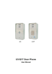
User ’s Manual of
WiFi Conference System
V1.1
CREATOR CHINA
Meaning of the symbols
■
Safety Instruction
Symbols are used in the Manual and devices, referring to the possible risk to users or others as well as
the damage to property, for helping you to safely and properly use the devices. The instruction and the
implications are as follows. Please make sure your correct understanding of these instructions before
using the Manual.
,
To remind user to conduct according to the attached operation
and maintenance instructions. If ignore these information,
death or injury could possibly happen.
To remind the user that the risky uninsulated voltage in the
device could caused electric shock to human.
CE authentication indicates the product is in line with the EU
safety regulation, and for assurance of safety use.
SGS Authentication indicates the product has reached the QC
standard of the global-biggest Swiss universe surveyor.
This product has acquired the ISO9001 International Quality
Authentication (Authentication authority: Germany Rheinland
TUV)
Caution: To avoid electric shock, please don't open the case,
nor put the useless parts in it. Please contact with qualified
service staff.
■
General Information Instruction
List the situation could cause unsuccessful operation or
setup, and relevant information needed to notice.
Important Notices
Caution
To ensure the device in reliable use and personal
safety, please abide by the following items when
in installation, use and maintenance:
Notice in installation
Please DO NOT use the product in following
places: the places with dust, oily smoke,
electrical conductive dust, corrosive gas,
inflammable gas; the places with high
temperature, due, rain and wind exposures; the
places endangered by shock and vibration.
Electric shock, fire and incorrect operation could
also cause damage and deterioration to the
product.
◆
◆
Note in Wiring
Installation and wiring shouldn't be conducted
until external electric power is cut off, otherwise,
electric shock or device damage could happen.
◆
◆The product is grounded by the earth lead of
the power cable. To avoid electric shock, the
earth lead is necessary to be connected with the
ground. Before making connection with the
output end or input end of the product, please
ensure it is correctly grounding.
◆Upon
finish wiring, remove the sundries.
Please cover up the terminal plate for avoiding
electric shock.
When conducting screw drilling and wiring
process, DO NOT let metal irons and wire lead
drop into the controller and air vent, which could
possibly cause fire, failure and accidental
operation.
◆Please DO NOT touch the terminal when with
◆After finishing the installation, it is necessary to
◆Don't clean up and screw the terminal tight
ensure there is no foreign matter including the
packing material like contact paper on the
ventilation surface, otherwise, it could cause
poor heat dissipation while running, as well as
fire, failure and accidental operation.
before power is off. Such operation could cause
electric shock when with electricity.
◆Avoid conducting wiring and plugging in/out
cable socket with electricity, otherwise, electric
shock, circuit damage could easily happen.
◆Installation
and wiring should be firm and
reliable. Poor contact could cause malfunction.
◆
With regard to the application situations with
strong interference, shielded cable should be
used for the input and output of HF signal, to
improve the anti-interference performance of the
system.
Note for Operation and Maintenance
electricity,
happen.
otherwise,
electric
shock
could
◆Please turn off the power before connecting or
disconnecting the communication signal cable,
peripheral modules or control units, otherwise,
device could be damaged and accidental
operation could happen.
◆Please DO NOT disassemble the device, so as
to avoid internal electric components damage.
◆It is necessary to read through the Manual and
fully ensure the safety, before altering the
program, trial running, starting and stopping
operation.
◆Button battery shouldn't be replaced before the
power is off. If it has to be replaced when the
device is running, it should be conducted by
professional electric technician wearing insulated
gloves.
Note for declaration of worthless.
Explosion of electrolytic capacitor on the circuit
board could happen when burning it.
◆
◆Please classify and dispose it. Don't dispose it
into household garbage.
◆Please
deal it as industrial waste, or in
accordance with local environmental protection
regulation.
Forward
User’s Manual of WiFi Conference System primarily introduces the operation of WiFi6101 Conference
Host, WiFi6102B Chairman Unit, WiFi6104B Delegate Unit, key parameters and general trouble
shootings.
The Manual serves as user's operation instruction, rather than for maintenance service purpose. Since
the date of release, any function or relevant parameter alteration will be in supplement instruction.
Please refer to the manufacturer or dealers for inquiry.
CREATOR Electronics own the copyright of the Manual. Without permission, any unit or person shall
not take part or total of the Manual for business purpose.
The copyright of the Manual is protected by Copyright Law of People’s Republic of China and other
Intellectual Property Law. Without written permission, any copy or distribution is prohibited.
Index
Chapter 1 Overview................................................................................................................................... 1
1.1
About Wireless Digital Network Conference System ................................................................. 1
1.2
System Features ......................................................................................................................... 1
1.3
System Device ............................................................................................................................ 1
1.4
System Diagram ......................................................................................................................... 2
Chapter 2 Host in WiFi Conference .......................................................................................................... 3
2.1 Overview .......................................................................................................................................... 3
2.2 CR-WiFi6101 Panel Instruction .................................................................................................... 3
2.3 CR-WiFi6101 Functions and Features ......................................................................................... 4
2.4 CR-WiFi6101 Panel Key Operation .............................................................................................. 5
2.4.1 Operation of MENU Keys................................................................................................ 5
2.4.2 AFC Key Operation ......................................................................................................... 6
2.5 ETHERNET Cable Production ...................................................................................................... 6
2.6 Connecting to Infrared Audio Distribution System ........................................................................ 6
2.7 Host Installation of CR-WiFi6101.................................................................................................. 7
2.8 CR-WiFi6101 Technical Parameters............................................................................................. 7
2.9 System Connection Diagram ........................................................................................................ 8
Chapter 3 WiFi Conference Unit ............................................................................................................... 9
3.1 Overview .......................................................................................................................................... 9
3.2 CR-WiFi6102/4B Panel Instruction.................................................................................................. 9
3.3 CR-WiFi6102/4B Functions and Features .................................................................................... 10
3.4 CR-WiFi6102/4B Operation Instruction ......................................................................................... 10
3.4.1 CR-WiFi6102/4B Setup ................................................................................................... 10
3.5 CR-WiFi6102/4B Technical Parameters ..................................................................................... 11
Chapter 4 Accessories ............................................................................................................................ 12
4.1 Power Recharge Cabinet .............................................................................................................. 12
4.2 CR-P2 Headset.............................................................................................................................. 12
4.3 CR-W6KL215B 215mm Heart-shaped Folded MIC Stand ............................................................ 13
4.4 CR-M4KL415 Knob 415mm MIC Stand(Optional) ........................................................................ 13
(
) ............................ 13
4.5 Power Recharger of CR-DOCK10B Wireless Conference Unit Optional
4.6 Power Adaptor............................................................................................................................. 13
User ’s Manual of WiFi Conference System
1
Chapter 1 Overview
1.1 About Wireless Digital Network
◆No shield, No interference
Conference System
Standard 802.11n WiFi technology, with strong
penetration, not influenced by the move of staff.
Thanks to the features of easy installation and
use, without space limitation, wireless conference
system has become a very important
development orientation of conference system
technology. Based on client’s need, CREATOR
independently
develops
wireless
digital
conference system featuring concise and
intelligent design philosophy, making everything
more convenient and flexible.
CREATOR Wireless Network Conference System
includes host, units and wireless access points.
The system can work at corresponding positions
after simple functional configuration without cable
connection.
Currently, whatever small conference room and
large conference hall can be a place for holding a
variety of conferences and seminars in
convenient and flexible way.
1.2 System Features
◆No need of wiring and drilling
◆Cost saving
Not in need of second renovation,
conference system is simple for use.
◆
Complete Functions
Expandable to connect to CREATOR digital
simultaneous interpretation system, the WiFi
conference system can realize corresponding
function.
◆Built-in antenna
Adopted built-in antenna design, in concise
appearance of the unit, and more importantly
avoiding broken or damaged antenna influencing
communication quality.
◆All-around status indication
Whatever the device is in sleep or working status,
device status, system order and key confirmation
can be display in the unit at a glance.
◆Reliable encryption system
WPA/WPA2 wireless encryption technology for
ensuring the privacy of the conference
1.3 System Device
WiFi
CREATOR express wireless digital network
conference system primarily includes the
following devices:
Host in CR-WiFi6101 Wireless Digital Network
Conference System
◆
◆Fashionable and decent design
◆Not limited by space, with quick installation ◆ Chairman
without influencing the site
WiFi conference system is for use right after
installation, only needing for placing on the
conference table whatever at which sites. After
use, it can be packed and moved.
unit in CR-WiFi6102B
Digital Network Conference System
Wireless
◆Delegate unit in CR-WiFi6104B Wireless Digital
Network Conference System
Guangzhou Creator electronics Ltd. Co 2012-01 WWW.CREATOR1997.COM
User’s Manual of WiFi Conference System
1.4 System Diagram
Guangzhou Creator electronics Ltd. Co 2012-01 WWW.CREATOR1997.COM
2
User’s Manual of WiFi Conference System
3
Chapter 2 Host in WiFi Conference
2.1 Overview
Control Host in CR-WiFi6101 Wireless Digital
Conference System is an very important bridge
between conference units and PC management.
Using the navigation keyboards in the panel,
along with LCD display, all conference functions
can be for centralized controlled. With multiple
conference modes selection (optional speaker
number and speech modes), super powerful
expanding function, DSP audio process, adopting
equalizer
module,
environmental
noise
suppression
technology,
compatible
with
CREATOR simultaneous interpretation system,
realizing modern high-tech conference.
2.2
CR-WiFi6101 Panel Instruction
Front Panel
:
:
Rear Panel
1) Power Switch
)
2 POWER
Power indicator is on only when with normal
power supply.
3
) LCD Monitor
、
、
、
、
Display MIC MODE MIC ACTIVE‘S BASS
TREBLE
VOLUME
AUDIO DOWN menu
configuration interface and parameters.
、
)
4 MENU
Menu keys for menu option setup
Guangzhou Creator electronics Ltd. Co 2012-01 WWW.CREATOR1997.COM
User’s Manual of WiFi Conference System
)
:
5 MODE
MIC mode setup key, with following modes:
A FIFO Early one exit priority mode
After reaching the number of turning it on, the
early opened speech unit will be closed by the
latter one.
B NORMAL Quota mode After reaching the
number of turning it on, delegates in need of
giving speech will be automatically queued up.
(
:
),
(
),
)
6
ACTIVE MICRO’S
Speakers number limitation, for configuration of
1/2/4/6 units for giving speech at the same time.
)
7
BASS
Bass increase key, for turning the bass in volume
output
)
TREBLE
8
Treble increase key, for turning the treble in
volume output.
)
9
VOLUME
For turning the output volume, press this key to
access to output volume setup menu.
)
10 AFC
Anti-feedback control key
4
)
15 IN
Audio input port, connecting to external audio
devices like those providing background music or
remote teleconference terminal output.
)
16 OUT
Audio output port is for connecting to amplifier to
increasing the voice of speakers, or connecting to
device for recording.
)
17 OUTPUTS
Audio output port, with 0-12 channel of audio
output, connecting to infrared transmission host.
)
18 INTERPRET
Interpreter port is for connecting to maximum 10
interpreter
units,
realizing
simultaneous
interpretation of 12 languages. Interpreter units
are taking hand-in-hand series connection.
SET ID
It is for configuring the ID of interpreter unit.
)
19 ETHERNET
Ethernet control port, is for connecting with
wireless AP, as well as exchanger to expand
Ethernet control function.
)
)Grounding port
21)Input port of system power
)
Host power input,
50/60HZ.
) 和
2.3
11 ANC
Noise suppress key
12 AGC
MIC auto increase control key
13
Left and right direction key, for locating the cursor
to setup the value needed.
)
14 ENTER
Enter execution key, for confirmation of all
operations.
20
supporting
AC100~240V
CR-WiFi6101 Functions and
Features
◆
Adopting WiFi signal transmission with
WPA/WPA2 digital encryption technology,
ensuring the privacy of conference, avoiding
tapping and malignant interference.
Guangzhou Creator electronics Ltd. Co 2012-01 WWW.CREATOR1997.COM
User’s Manual of WiFi Conference System
◆With 1-way RJ45 port, for direct connecting
with a wireless AP, or 100M network exchanger
for application in multiple sites.
◆ With
1-way interpretation unit port, for
connecting with maximum 10 interpretation units.
◆For realizing simultaneous interpretation of 12
languages.
◆One group of LINE IN ports for connecting with
5
LCD screen instruction
LCD monitor will be kept on for long time before
turning on the host, and display current system
status and operation information with white fonts
and blue background.
Key indicator instruction
When key indicator is in red or flashing, red
indicator flashes for once indicates successful
selection of key function or parameter, and LCD
monitor will display corresponding information.
external audio devices.
◆Provide one group of MIC remixed output, for
live conference recording along with recording
device.
◆Support manual adjustment of the bass, treble
and volume
◆Built-in DSP feedback suppression function
◆Adopting full-metal case, both the wiring and
case are with intensified grounding, with contact
12kv, air 15kv antistatic capacity.
◆The host can be installed in a 19-inch standard
cabinet.
2.4
CR-WiFi6101 Panel Key
2.4.1
Operation of MENU Keys
Menu keys operation includes the configuration of
MIC MODE, MIC ACTIVE’S, BASS, TREBLE,
VOLUME, AUDIO DOWN, with following basic
steps.
、
1 Press “MENU” key, LCD monitor displays first
option “MIC MODE”.
、
2 Press“ ”or“ ”key to navigate all options in
order. At the meantime, LCD monitor displays
current operation status. Select the option to
configure, press “ENTER” to confirm it.
、
3 After accessing to parameters setup screen,
press“ ”or“ ” key to more cursor to select the
setup value.
、
4 Press“ENTER”key to confirm the parameter
selected.
Operation
For the convenience of management and use,
CREATOR designs navigation panel and LCD
monitor facilitating your operation of system. It
takes simple steps, which is easy to learn.
Instruction of basic operation
Functional key----direction key----ENTER”confirm
key---direction key--- “ENTER”confirm
After setting, system will auto exit if without any
operation for about 10 seconds.
Before
exiting
setup
screen,
press
“MENU”key to display the option of last operation,
rather than the first option.
Example:
Configure MIC mode as Normal (quota mode)
with following steps
1 In navigation panel, press “MENU” key to
access to MIC mode to select screen. At the
meantime, indicator will be on for once, and LCD
monitor display relevant information.
、
:
Guangzhou Creator electronics Ltd. Co 2012-01 WWW.CREATOR1997.COM
User’s Manual of WiFi Conference System
、
6
,
2 Press“ ”or “ ” to move the cursor every
time when pressing the direction key, the indicator
will be on for once; select “MIC MODE” to
configure, press “ENTER” to confirm. Then
“ENTER” key indicator will be on, and LCD
monitor displays the setup of MIC mode option.
、
,
3 Press“ ”or “ ” to move the cursor Select
“NORMAL (quota mode), at the meantime the
indicator will be on, and LCD monitor displays
relevant information.
T568A line order
1
G
W
2
3
O
G
W
、
4 Finally, press“ENTER”to finish the operation.
You may directly press MIC MODE in navigation
panel, access to menu setup, and follow the
above step 3 and step 4 to finish the operation. It
will be more convenient and express. Likewise
the other keys on navigation panel (including
ACTIVE MICRO’S, BASS, TREBLE, VOLUME).
2.4.2
AFC Key Operation
Press the AFC key on host panel to initiate
anti-feedback function, at the same time, the
corresponding indicator will be on. Press AFC key
again to stop the function and the indicator will be
off.
The operation of ANC (anti-noise control) function
and AGC (auto-gain control) function on the panel
is the same as AFC key.
2.5
ETHERNET Cable Production
The system adopts CAT-5 (category 5 cabling) as
wiring, connecting the network devices via RJ-45
connectors on both ends of
CAT-5. The standard connection of UTP is not
stipulated freely, as symmetric layout of cable
connectors has to be ensured. In this way, the
internal interference arising within cables can be
offset. Generally, HSYV has 4 pairs of twisted thin
lines inside, marked in different colors.
Two connections of twist pair: EIA/TIA 568B
standard and EIA/TIA 568A standard.
4
5
6
B
B
W
O
7
Br
W
8
Br
T568B line order
1
O
W
2
3
G
O
W
4
5
6
B
B
W
G
7
Br
W
8
Br
G:green; W: white; O:orange; B: blue; Br:brown
Direct-through line both ends are connected in
accordance with T568B line order.
Cross wire one end is connected in accordance
with T568A line order
another end is in
accordance with T568B line order.
:
:
When
,
connecting
to
network
router,
direct-through wire connection is adopted; when
connecting to PC control, cross wire connection is
adopted.
2.6
Connecting to Infrared Audio
Distribution System
The connection between wireless conference
system and CREATOR infrared audio distribution
system is via 12-way audio output in
CR-WiFi6101 host and 11+1-way audio input
channels. Connect any way to conduct
simultaneous transmission. The hosts for use with
CREATOR infrared audio distribution system are:
CR-IR3000 Infrared Transmission Host
CR-IR2000-12 Infrared Transmission Host
◆
◆
Guangzhou Creator electronics Ltd. Co 2012-01 WWW.CREATOR1997.COM
User’s Manual of WiFi Conference System
See Chapter 2.9 System Connection Diagram for
detailed connection approach.
2.7
Host Installation of
CR-WiFi6101
The host of WiFi conference system can be
installed in a standard 19-inch cabinet. The host
has standard accessories of a pair of host
installation supports. See the following diagram
for installation:
2.8
Max power output
at 8Pin avionics
port
7
60W
Dynamic range
>80dB
Frequency
response
20Hz~20KHz
Communication
distance between
host and AP
>100m
Dimension
483LX130WX48H mm
Power America
Japan
AC100V~AC120V 60Hz
(
,
)
Power(Eurasia)
( )
AC200V~AC240V 50Hz
CR-WiFi6101 Technical
Parameters
External control port
RJ45 port
Display
1602LCD monitor
Translation unit port
8Pin avionics port
S/N
Harmonic distortion
Over-carrier distortion
Cross talk
1KHz
(
)
Static
consumption
attenuation
power
Max. power consumption
>80dB
<0.5%
<1%
>50dB
3W
70W
Guangzhou Creator electronics Ltd. Co 2012-01 WWW.CREATOR1997.COM
User’s Manual of WiFi Conference System
2.9
System Connection Diagram
Guangzhou Creator electronics Ltd. Co 2012-01 WWW.CREATOR1997.COM
8
User’s Manual of WiFi Conference System
9
Chapter 3 WiFi Conference Unit
3.1 Overview
The design of CR-WiFi6102/4B wireless
conference unit adopts special technique for
ensuring the device is stable and durable.
Delicate appearance design fits in well with any
conference room.
With built-in antenna, each unit has built-in high
performance battery group, providing up to 9
working hours. All functions in conference unit
can be realized on unit panel. Adopting encrypted
WiFi transmission technology, the speech is
ensured not to be captured by unauthorized
parties.
3.2 CR-WiFi6102/4B Panel
Instruction
:
Top view
:
Bottom view
)
,
1 Headset jack insert the phone plug to hear the
speech.
)
2 MIC power indicator will be on when MIC
switch is on.
)
),
3 Plugging MIC stand base (MIC socket
adopting 5-core high-density avionics interface,
with screw turning connector making it stable in
connection.
)
4 Unit power switching key, press it to turn on the
unit, at the meantime the indicator will be on.
)
5 LCD monitor, displaying relevant operation with
blue backlight and white fonts
)
6 MIC speech switching key, press it to turn on
the indicator, at the meantime the indicator of MIC
power will also be on.
) Power indicator.
8)Volume adjusting and parameter setup key.
9 ) Power input port, self-adapting to DC 12v
7
system power input.
Guangzhou Creator electronics Ltd. Co 2012-01 WWW.CREATOR1997.COM
User’s Manual of WiFi Conference System
)
10 Unit power recharging ports, with 4 ports for
recharging corresponding to recharging cabinet.
10
3.4 CR-WiFi6102/4B Operation
Instruction
3.3 CR-WiFi6102/4B Functions and
3.4.1 CR-WiFi6102/4B Setup
◆ Each
conference unit is equipped with
independent IP address;
Wireless conference unit comprises ROUTER
and IP setup. And the Router includes two
components of SSID and PASSWORD. The
following is the instruction in details:
◆ WiFi
3.4.1.1 ROUTER Setup
Features
transmission technology, strict digital
protection, ensuring the privacy of conference,
avoiding tapping and malignant interference;
◆Condenser heart-shaped directional MIC, with
dual-color indicator ring, it turns red when giving
speech. Red light flashes if in short of power;
◆ With
one-way 3.5mm stereo headset jack,
capable for volume adjustment;
◆ LCD
monitor with backlight, displaying MIC
on/off, IP setup, SSID setup, password setup etc
◆Chairman unit is limited by maximum speaker
number;
◆ Chairman unit is authorized to suspend the
speech in delegate unit;
◆ Chairman
unit has privilege to fully control
conference order;
◆With built-in rechargeable battery supporting
the speech up to 9 hours continuously;
◆Adopts special 5-cord high-density avionics
◆
SSID setup
Step 1 Access to interface
After correctly connecting the device, press the
ON/OFF key on panel, LCD monitor will display
Startup…., press and hold MIC key to access to
Unit Set Menu screen, ROUTER is displayed on
left in the monitor, and IP at the right. Press
“ ”key to access to router setup menu. Then
SSID will be displayed on the left in the monitor,
and PASSWORD on the right, press“ ” to
access to router SSID setup screen.
:
-
-
:
Step 2 Setup
After accessing to SSID setup screen, LCD
monitor has default display of WIFI, and the
cursor will appear under the first letter of “W”,
hinting to set up first letter. Use“-” and“+” keys to
move the cursor, press MIC keyboard to confirm
execution.
For example: To set up the 4th letter, move the
cursor to letter “I”, press MIC key, then letter
“I” will flash, press “-” and “+” keys to set it up
with value changed in order ranging 0 to 9, a to f
and A to F. Set up the value and press MIC key to
confirm the operation. LCD monitor will display
the value configured. That’s the end of operation.
Port;
◆ Adopts
professional conference MIC, with
screw turning connector for plugging at will;
◆With feedback suppress function;
Likewise, the other values can be configured in
this way. And value is for up to 10 digits. After
configuring SSID, press and hold MIC key, LCD
monitor will display “Set SSID OK”, then SSID
setup is finished. Press any key or wait for 1
Guangzhou Creator electronics Ltd. Co 2012-01 WWW.CREATOR1997.COM
User’s Manual of WiFi Conference System
second to return to the setup screen of Router Set
Menu.
3.5
11
CR-WiFi6102/4B Technical
Parameters
When the value turns 0, press “-” key to
Connection components
delete the digit, then this digit and all the letters
after it will not be displayed any more.
For example, if the value is WIFI0af, move the
cursor to under 0, press MIC, 0 will flash, and
press“-” key, then LCD monitor will display WIFI
only, without letter 0 and the value after it.
Base
To plug and unplug the MIC
Headset jack
One 3.5mm 0.14 inch stereo
headset jacks
Power
DC input power connecting
after
discharging
battery
group
◆ PASSWORD setup
Electrical Index
In Router Set Menu screen, press “+”key to
access to PASSWORD screen, the setup
approach is the same as that for SSID. But in
PASSWORD setup, the function of pressing “-”
key to delete 0 and the value after it doesn’t exist.
And the value is fixed with 10 digits.
Default value is 9999999999. LCD monitor
display * to represent all values. Once it’s
changed, it is necessary to re-input the 10-digit
password.
)
(
)
~
Frequency
response
30Hz 20kHz
Headset load
impedance
>32 ohm<1K ohm
Wireless index
standard
IEEE 802.11g
IEEE Draft 2.0 802.11n
Wireless
frequency
range
2.400-2.500GHz
4.900-5.850GHz
transmitting
power
15dBm
antenna gain
2dBi
Specification
3.4.1.2 IP Setup
In Router Set Menu screen, press MIC key to exit
and access to Unit Set Menu screen, press “+”key
to access to IP setup screen. The operation is the
same as that for setup SSID.
the function of pressing “-” key to delete 0 and the
value after it doesn’t exist. And value
changing order is 0 to 9.
Factory default IP is 192.168.2.110
(
, IP
Battery output
voltage
7.2V
Battery
capacity
4800mAH
Working time
9 hours
Static standby
time
13 hours
Charging time
3 hours
Color
Black
Dimension
150Lx150wx59H
address ranges between 192.168.2.31 and
192.168.2.254. Host IP address 192.168.2.16. Be
sure not to have IP address conflict with router.
Guangzhou Creator electronics Ltd. Co 2012-01 WWW.CREATOR1997.COM
User’s Manual of WiFi Conference System
12
Chapter 4 Accessories
Technical Parameters
4.1 Power Recharge Cabinet
CR-WFDS06 is the power recharge cabinet for
the units in WiFi conference system, for
recharging up to 6 units at the same time. Power
input can be in series connection. It is also for
express recharging, with maximum recharging
time of 3 hours.
Power recharging diagram
( )
Dimension
497LX397WX120H mm
Weight
About 5kg
Power
consumption
100W
Power
consumption
stand-by
3W
(
)
Diagram of series connection among recharge
cabinet
Features and benefits
Recharging up to 6 units;
Universal power;
Power input can be in series connection;
Express recharging, with maximum recharging
time of 3 hours;
Apart from recharging, the case can hold the
unit;
◆
◆
◆
◆
◆
Controller and indicator
On/Off;
Recharging status indication.
◆
◆
:
Function description
To monitor conference units
To free from influence
in conference system
With1.5m cable
Hi-fi quality.
◆
◆
◆
◆
;
;
;
Technical Parameters
Inter-connection
Series port for power supply Europe type male
socket;
24 recharging contacts;
◆
◆
4.2 CR-P2 Headset
,
Unit port
3.5mm mono connector
Frequency response
30Hz -16KHz
Sensitivity
90dB
S/N
Distortion
Impedance
Dynamic range
> 80dB
< 0.1dB
32 Ω
> 85 dB
Guangzhou Creator electronics Ltd. Co 2012-01 WWW.CREATOR1997.COM
User’s Manual of WiFi Conference System
4.3 CR-W6KL215B 215mm
Heart-shaped Folded MIC Stand
◆ Power supplyand power recharge to speech
unit.
◆INPUT:100V-240ac--1.5A;
◆OUTPUT:OUTPUT DC12V--3A。
Function description
Heart-shaped directional
Condenser MIC
High-density 5-core
Avionics interface.
Normal speech indicator
Speech application indicator
◆
◆
◆
◆
;
;
4.4 CR-M4KL415 Knob 415mm MIC
Stand(Optional)
Function description
Heart-shaped directional
Condenser MIC
High-density 5-core
Avionics interface.
Normal speech indicator
Speech application indicator
◆
◆
◆
◆
4.5
;
;
Power Recharger of
CR-DOCK10B Wireless
Conference Unit(
(Optional)
)
Function Description
◆Power recharge for the
speech unit in wireless
conference
With 4 anti-skidding food pads, for fastening on
the table while recharging in work.
Power recharge indicator
◆
◆
4.6
13
Power Adaptor
Function description
Guangzhou Creator electronics Ltd. Co 2012-01 WWW.CREATOR1997.COM
(
CREATOR CORPORATION CHINA
Copyright by CREATOR
)
:
Last Revision 01/2012